1
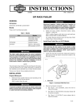
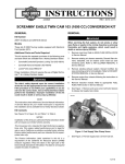
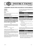
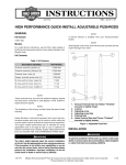
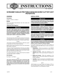
-J05183
REV. 2010-06-04
SCREAMIN' EAGLE "HEAVY BREATHER" RACE VELOCITY STACK
KIT
GENERAL
Kit Contents
Kit Numbers
See Figure 1 and Table 1.
29400013
INSTALLATION
Models
For model fitment information, see the P&A Retail Catalog or
the Parts and Accessories section of www.harley-davidson.com
(English only).
NOTES
This kit is intended for race applications only. Engine-related
performance parts are intended FOR THE EXPERIENCED
RIDER ONLY.
Running an engine with out an air cleaner can result in
severe engine damage.
Additional Parts Required
To prevent accidental vehicle start-up, which could cause
death or serious injury, disconnect battery cables (negative
(-) cable first) before proceeding. (00307a)
Disconnect negative (-) battery cable first. If positive (+)
cable should contact ground with negative (-) cable connected, the resulting sparks can cause a battery explosion,
which could result in death or serious injury. (00049a)
1.
LOCTITE® 243 (Blue) Threadlocker and Sealant is needed for
proper installation of this kit. A 0.5 mL pack of Loctite 243 is
included with this kit. A 6.0 mL tube (Part No. 99642-97) is
available from a Harley-Davidson dealer.
Proper installation of this kit requires breather screws (Part No.
29465-08), which are OE equipped on 2008 and later Touring
models. If the motorcycle is not equipped with these breather
screws, separate purchase is required.
The rider's safety depends upon the correct installation
of this kit. Use the appropriate service manual procedures.
If the procedure is not within your capabilities or you do
not have the correct tools, have a Harley-Davidson dealer
perform the installation. Improper installation of this kit
could result in death or serious injury. (00333a)
When servicing the fuel system, do not smoke or allow
open flame or sparks in the vicinity. Gasoline is extremely
flammable and highly explosive, which could result in
death or serious injury. (00330a)
Original Equipment (OE) Air Cleaner Removal
For EFI (fuel-injected) models: Have a Harley-Davidson
dealer recalibrate the ECM prior to air cleaner installation.
2.
Remove the air cleaner backplate following the instructions
in the service manual. Retain the two breather screws (A)
removed from the backplate (see Figure 1). The remaining
parts can be discarded.
3.
See Figure 1. Remove and discard induction module
bracket (B).
NOTES
This instruction sheet references service manual information.
A service manual for your model motorcycle is required for this
installation and is available from a Harley-Davidson dealer.
Refer to the service manual and follow the instructions
given to remove the seat and disconnect the battery
cables, negative (-) cable first. Retain all seat mounting
hardware.
Back Plate Installation
The following caution and note apply to EFI models only.
NOTE
When servicing the velocity stack, apply Loctite 243 (blue) to
all threaded fasteners (both male and female threads).
You must recalibrate the ECM when installing this kit.
Failure to properly recalibrate the ECM can result in severe
engine damage. (00399b)
4.
Install the new O-rings (11) in the grooves around the
breather screw holes on induction module side of the
backplate (10).
NOTE
5.
Remove the backing from the adhesive side of the backplate gasket (12). Carefully align the holes, and install the
gasket on the induction module side of the backplate.
See a Harley-Davidson dealer for ECM (Electronic Control
Module) calibration.
-J05183
1 of 3
6.
Insert the breather screws (removed in Step 2) through
the backplate. Apply a small amount of Loctite (13) to the
breather screw threads and the mating tapped holes in
the cylinder head, then install the screws into the cylinder
head. DO NOT tighten completely at this time.
7.
Apply a small amount of Loctite to the backplate mounting
screw (9) threads. Install the screws all the way through
the backplate and gasket until the screw threads are captured in the induction module. DO NOT tighten completely
at this time.
8.
Alternately tighten the two breather screws to 120-144 inlbs (13.6-16.3 Nm).
9.
Lubricate the O-rings (7) with clean engine oil or white
lithium grease.
Install the O-rings onto the breather plugs. Press the
breather plugs (6) into the breather screw cavities.
10. Tighten the three backplate mounting screws to 55-60 inlbs (6.2-6.8 Nm).
Velocity Stack and Air Tube Installation
11. With the countersunk holes facing outward, slide the
mounting ring (5) all the way onto the intake tube (3), up
to the flange.
12. Place the gasket (8) against the opposite side of the
flange.
13. Align the holes in the gasket with the mounting ring (5)
holes and notches in the intake tube flange.
-J05183
14. Apply a small amount of Loctite to the threads of the three
flat head screws (4).
15. Secure the intake tube, mounting ring and gasket to the
backplate, and tighten the screws to 55-60 in-lbs (6.2-6.8
Nm).
16. Install the velocity stack (2) onto the intake tube until
velocity stack bottoms out on tube. Position velocity stack
so that the set screw (1) is located towards the inside of
the tube closest to the engine.
Tighten the set screw to 30-40 in-lbs (3.4-4.5 Nm).
Connect positive (+) battery cable first. If positive (+) cable
should contact ground with negative (-) cable connected,
the resulting sparks can cause a battery explosion, which
could result in death or serious injury. (00068a)
17. Refer to the service manual and follow the instructions
given to connect the battery cables, positive (+) cable first,
and install the seat.
After installing seat, pull upward on seat to be sure it is
locked in position. While riding, a loose seat can shift
causing loss of control, which could result in death or
serious injury. (00070b)
2 of 3
SERVICE PARTS
is06615
10
A
12
9
11
8
7
6
5
3
4
1
2
Figure 1. Service Parts: Screamin' Eagle Heavy Breather Race Velocity Stack Kit
Table 1. Service Parts Table
Item
Description (Quantity)
Part Number
1
Cup point, hex drive set screw
4695
2
Velocity stack
27200001
3
Intake tube, machined
29400012
4
Screw, flat head hex drive (3)
2986
5
Mounting ring
29826-08A
6
Plug (2)
29830-05A
7
O-ring (4)
10925
8
Gasket
25700028
9
Hex socket, button head screw (3)
926
10
Backplate, machined
29000014
11
O-ring, #2-113 (2)
11292
12
Gasket, throttle body
27300031
13
Loctite®
94635-98
243 Blue, 0.5 ml tube
Items mentioned in text, but not included in kit:
A
OEM breather screw (2) (purchased separately if missing)
B
Induction module bracket (not shown)
-J05183
29465-08
3 of 3