1
4241724-PT-Rev A
By Jacobsen
Parts & Maintenance Manual
Manual de Peças & Manutençao
Cushman® Turf Truckster®
With Four Post ROPS
Com estrutura de protecção contra capotamento de 4 colunas
84063 – Kubota® D1105-E3B Diesel Engine, MT
84064 – Kubota® D1105-E3B Diesel Engine, MT, EC
84067 – Suzuki® K6 Gas Engine, MT
84068 – Suzuki® K6 Gas Engine, AT
84069 – Suzuki® K6 Gas Engine, RV and Utility
84063 – Motor Diesel Kubota® D1105-E3B, MT
84064 – Motor Diesel Kubota® D1105-E3B, MT, EC
84067 – Motor a Gasolina Suzuki® K6, MT
84068 – Motor a Gasolina Suzuki® K6, AT
84069 – Motor a Gasolina Suzuki® K6, RV e Utility
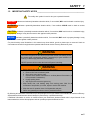
WARNING
If incorrectly used, this machine can cause severe injury. Those who use
and maintain this machine should be trained in its proper use, warned of its
dangers and should read the entire manual before attempting to set up,
operate, adjust or service the machine
ATENÇÃO
Esta máquina pode causar ferimentos graves se for utilizada incorrectamente.
A pessoa responsável pela sua utilização e manutenção deve ser previamente
instruída para a sua utilização correcta, avisada sobre os perigos que ela pode
causar e deve ler todo o manual antes de tentar preparar, conduzir, afinar ou
reparar a máquina.
GB
PT
United
Kingdom
Portugal
When Performance Matters.™
FOREWORD
This manual contains adjustment, maintenance,
troubleshooting instructions and parts list for your new
Jacobsen® machine. This manual should be stored with
the equipment for reference during operation.
The serial plate is located on the frame rail under the
steering wheel. Jacobsen recommends you record these
numbers below for easy reference.
CHARLOTTE, NC, USA
1 800 848 1636
Jacobsen.com
Before you operate your machine, you and each operator
you employ should read the manual carefully in its
entirety. By following the safety, operating and
maintenance instructions you will prolong the life of your
equipment and maintain its maximum efficiency.
MODEL
xxxxx
DATE CODE
xxxxx
LABEL # xxxxxxxx
SERIAL #
*xxxxxxxx*
If additional information is needed contact your Jacobsen
Dealer.
Lb/kg W Batt
Nom Power Hp/kw
Suggested Stocking Guide
To Keep your equipment fully operational and productive, Jacobsen suggests you maintain a stock of the more
commonly used maintenance items. We have also included part numbers for additional support materials and training
aids.
❑ Overnight
To order any of the following material:
❑ 2nd Day
1. Write your full name and complete address on your
order form.
3. Order by the quantity desired, the part number, and
the description of the part.
2. Explain where and how to make shipment:
4. Send or bring the order to your authorized Jacobsen
Dealer.
❑ UPS
❑ Regular Mail
Service Parts
Qty. Part No.
4113986
550489
4175560
4117092
5000919
Description
Qty. Part No.
Diesel Engine Oil Filter
Diesel Engine Fuel Filter Element
Diesel Alternator-Power Steering Belt
Diesel Hydraulic Pump Belt
Diesel Engine Air Filter Element
2701908
2701898
4139265
4235370
840352
885249
Description
Gas Engine Oil Filter
Gas Engine Fuel Filter
Gas Alternator-Power Steering Belt
Gas Governor-Hydraulic Pump Belt
Gas Engine Air Filter Element
Hydraulic FIlter Element
Service Support Material
Qty. Part No.
4241725
4241724
4160162
4241728
Description
Qty.
Safety & Operation Manual
Parts & Maintenance
Kubota D1105 Engine Parts Manual
Suzuki K6A Engine Parts Manual
Part No.
4171642
4171675
4171985
4239442
These are the original instructions verified by
Jacobsen A Textron Company
© Copyright 2011, Jacobsen, A Textron Company. “All rights
reserved, including the right to reproduce this material or portions
thereof in any form.”
en-2
Litho in U.S.A. 1-2011
Description
MT Truck Service Manual
AT Truck Service Manual
Suzuki K6A Service Manual
Accessory Manual
Proposition 65 Warning
This product contains or emits
chemicals known to State of California
to cause cancer and birth defects or
other reproductive harm.
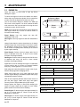
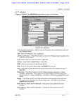
Table of Contents
1
1.1
1.2
2
2.1
2.2
3
3.1
3.2
3.3
3.4
3.5
3.6
3.7
3.8
4
4.1
4.2
4.3
4.4
4.5
4.6
4.7
4.8
4.9
4.10
5
5.1
5.2
5.3
5.4
5.5
5.6
5.7
5.8
5.9
5.10
Safety
Operating Safety ........................................ 4
Important Safety Notes .............................. 5
Vehicle Identification Numbers
Vehicle Identification Number .................... 6
Engine Identification Numbers ................... 6
Specifications
Product Identification ................................. 7
Diesel Engine ............................................. 7
Gas Engine ................................................ 7
vehicle ........................................................ 8
Gear Ratios ................................................ 8
Weights and Dimensions ........................... 8
Accessories & Support Literature .............. 9
Declaration of Conformity ........................ 10
Adjustments
General .................................................... 12
Engine Access ......................................... 12
Front Cowl Access ................................... 13
Access Panels ......................................... 13
Diesel Alternator Belt ............................... 14
Diesel Hydraulic Pump Belt ..................... 14
Gas Power Steering - Alternator Belt ....... 14
Gas Hydraulic Pump Belt ......................... 15
Parking Brake Cable ................................ 15
Torque Specification ................................ 16
Maintenance
General .................................................... 17
Engine ...................................................... 17
Engine Oil ................................................ 18
Power Steering Reservoir ........................ 19
Muffler and Exhaust ................................. 19
Engine Overheat Procedure .................... 19
Cooling System ........................................ 20
Air Filter ................................................... 21
Jump Starting ........................................... 21
Battery ..................................................... 22
5.11
5.12
5.13
5.14
5.15
5.16
5.17
5.18
5.19
5.20
5.21
5.22
5.23
5.24
5.25
5.26
5.27
5.28
5.29
5.30
5.31
5.32
6
6.1
7
7.1
7.2
7.3
7.4
7.5
8
9
9.1
9.2
9.3
Charging Battery .......................................22
Hydraulic Hoses ........................................23
Hydraulic Reservoir and Filter ..................23
Fuel ...........................................................24
Fuel System ..............................................24
Tire Pressure ............................................25
Tire Removal and Installation ...................25
Raising the vehicle ....................................26
Towing the Vehicle ...................................27
Governor Oil Level ....................................27
Hydraulic Brakes .......................................28
Differential Fluid ........................................29
Diesel Engine Manual Transmission ........29
Gas Engine Manual Transmission ............30
Gas Engine Automatic Transmission ........30
Electrical System ......................................31
Dash Panel ...............................................31
Headlight Replacement ............................32
Tail Light Replacement .............................32
EFI Diagnostic Check ...............................33
Care and Cleaning ....................................33
Storage .....................................................34
Troubleshooting
General ..................................................... 35
Maintenance & Lubrication Charts
General ..................................................... 36
Lubrication Chart ......................................36
Maintenance Charts ..................................37
Common Replacement Parts ....................38
Kubota Diesel Engine Service Parts .........38
Notes
Parts Catalog
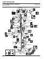
How To Use The Parts Catalog ................ 40
To Order Parts ..........................................40
Table Of Contents .....................................41
en-3
1
SAFETY
1
SAFETY
1.1
OPERATING SAFETY ______________________________________________________
! WARNING
EQUIPMENT OPERATED IMPROPERLY OR BY UNTRAINED PERSONNEL CAN BE DANGEROUS.
Familiarize yourself with the location and proper use of all controls. Inexperienced operators should receive instruction
from someone familiar with the equipment before being allowed to operate the machine.
1. Safety is dependent upon the awareness, concern
and prudence of those who operate or service the
equipment. Never allow minors to operate any
equipment.
2.
It is your responsibility to read this manual and all
publications associated with this equipment (Safety &
Operation Manual, Engine Manual, accessories, and
attachments). If the operator cannot read English it is
the owner’s responsibility to explain the material
contained in this manual to them.
3.
Learn the proper use of the machine, the location and
purpose of all the controls and gauges before you
operate the equipment. Working with unfamiliar
equipment can lead to accidents.
4.
Never allow anyone to operate or service the machine
or its attachments without proper training and
instructions or while under the influence of alcohol or
drugs.
5.
Wear all the necessary protective clothing and
personal safety devices to protect your head, eyes,
ears, hands, and feet. Operate the machine only in
daylight or in good artificial light.
6.
7.
8.
9.
Evaluate the terrain to determine what accessories and
attachments are needed to properly and safely perform
the job. Only use accessories and attachments
approved by Jacobsen.
Stay alert for holes in the terrain and other hidden
hazards.
Inspect the area where the equipment will be used.
Pick up all the debris you can find before operating.
Beware of overhead obstructions (low tree limbs,
electrical wires, etc.) and also underground obstacles
(sprinklers, pipes, tree roots, etc.) Enter a new area
cautiously. Stay alert for hidden hazards.
Never allow anyone near the machine while in
operation. The owner/operator can prevent, and is
responsible for, injuries inflicted to themselves, to
bystanders, and damage to property.
10. Do not carry passengers. Keep bystanders and pets a
safe distance away.
11. Never operate equipment that is not in perfect working
order or is without decals, guards, shields, or other
protective devices securely fastened in place.
12. Never disconnect or bypass any switch.
en-4
13. Do not change the engine governor setting or
overspeed the engine.
14. Carbon monoxide in the exhaust fumes can be fatal
when inhaled. Never operate the engine without proper
ventilation or in an enclosed area.
15. Fuel is highly flammable; handle with care.
16. Keep the engine clean. Allow the engine to cool before
storing and always remove the ignition key.
17. Place transmission in Neutral, depress clutch and
engage parking brake before starting the engine
(motor). Start the engine only when sitting in operator’s
seat never while standing beside the unit.
18. Equipment must comply with the latest federal, state,
and local requirements when driven or transported on
public roads. Watch out for traffic when crossing or
operating on or near roads.
19. Local regulations may restrict the age of the operator.
20. Operate the machine up and down the face of the
slopes (vertically) not across the face (horizontally).
21. To prevent tipping or loss of control do not start or stop
suddenly on slopes. Reduce speed when making
sharp turns. Use caution when changing directions.
22. Always use the seat belt when operating vehicles
equipped with a Roll Over Protective Structure
(ROPS).
Never use a seat belt when operating vehicle
without a ROPS.
Accessory ROPS will continue to be offered for all
equipment currently covered. This allows for the
outfitting of any machines without previous ROPS
installations or replacement of damaged structures.
23. Keep legs, arms, and body inside the seating
compartment while the vehicle is in motion.
24. Always shift transmission to 1st Gear (Manual
Transmission) or Park (Automatic Transmission),
engage parking brake, and stop engine before leaving
the vehicle.
25. Charge batteries in an open well ventilated area away
from spark and flames. Unplug charger before
connecting and disconnecting charger from battery.
Wear protective clothing and use insulated tools.
26. Disconnect the battery cables before performing any
welding operations on this vehicle.
SAFETY
1.2
1
IMPORTANT SAFETY NOTES ________________________________________________
This safety alert symbol is used to alert you to potential hazards.
DANGER - Indicates an imminently hazardous situation which, if not avoided, WILL result in death or serious injury.
WARNING - Indicates a potentially hazardous situation which, if not avoided, COULD result in death or serious
injury.
CAUTION - Indicates a potentially hazardous situation which, if not avoided, MAY result in minor or moderate injury,
and property damage. It may also be used to alert against unsafe practices.
NOTICE - Indicates a potentially hazardous situation which, if not avoided, MAY result in property damage. It may
also be used to alert against unsafe practices.
For pictorial clarity some illustrations in this manual may show shields, guards or plates open or removed. Under no
circumstances should this equipment be operated without these devices securely fastened in place.
! WARNING
The Interlock System on this vehicle prevents the vehicle from starting unless
the clutch pedal is depressed (Manual Transmission) or gear selector is in
Park (P) or Neutral (N) (Automatic Transmission).
NEVER operate vehicle unless the Interlock System is working.
! WARNING
1. Before leaving the operator’s position for any reason:
a. Remove foot from accelerator pedal.
b. Slow vehicle using service brake.
c. Depress clutch and shift transmission to 1st Gear (Manual Transmission, or
Park (Automatic Trnasmission).
d. Engage parking brake.
e. Stop engine and remove the ignition key.
2. Keep hands, feet, and clothing away from moving parts. Wait for all
movement to stop before you clean, adjust or service the machine.
3. Keep the area of operation clear of all bystanders and pets.
4. Never carry passengers unless a seat is provided for them.
By following all instructions in this manual you will prolong the life of your machine and maintain its maximum efficiency.
Adjustments and maintenance should always be performed by a qualified technician.
If additional information or service is needed contact your Authorized Jacobsen Dealer who is kept informed of the
latest methods to service this equipment and can provide prompt and efficient service.
en-5
2
2
2.1
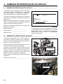
VEHICLE IDENTIFICATION NUMBERS
VEHICLE IDENTIFICATION NUMBERS
VEHICLE IDENTIFICATION NUMBER _________________________________________
The Vehicle Identification Number (VIN), consisting of the
model number, date code, and serial number, is printed
on the Nameplate/Identification Decal attached to the
cross member under the dash.
The serial number is also stamped on the cross member.
It is located to the left of the Nameplate/Identification
Decal.
NOTE: Reference to the Front, Rear, Left, and Right
sides of the vehicle are always determined by the
operator’s seated position.
CHARLOTTE, NC, USA
1 800 848 1636
Jacobsen.com
MODEL
xxxxx
DATE CODE
xxxxx
LABEL # xxxxxxxx
SERIAL #
*xxxxxxxx*
Lb/kg W Batt
Nom Power Hp/kw
Record the Vehicle Identification information below for
easy reference.
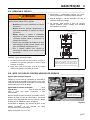
Figure 2A
Date Code: _________________________
Always provide the Vehicle Identification Number of the
unit when ordering replacement parts or requesting service
information. Vehicle Identification Numbers must appear
Serial Number: ______________________
on all correspondence concerning this vehicle.
Model Number: ______________________
2.2
ENGINE IDENTIFICATION NUMBERS _________________________________________
The Truckster is equipped with either a Kubota® three
cylinder, diesel powered, liquid cooled, four cycle engine
or a Suzuki® three cylinder gas powered, liquid cooled,
four cycle engine.
The Engine Serial Number for the Kubota engine is on a
plate located on the valve cover.
The Engine Serial Number for the Suzuki engine is
stamped onto the upper engine block on the right side of
the engine under the engine mount and may be partially
hidden by the electrical harness. The serial number is
also hand printed on the fuel rail.
Engine Serial No.
Kubota Diesel
Record the Engine Serial Number below for easy
reference.
Figure 2B
Engine Serial Number: _________________________
Engine Serial No.
K6A Suzuki
en-6
SPECIFICATIONS
3
3
SPECIFICATIONS
3.1
PRODUCT IDENTIFICATION _________________________________________________
84063 ............................Turf Truckster, liquid cooled
diesel engine, 4 speed manual
transmission, 11.16:1 2 speed
differential, mechanical PTO,
and four post ROPS.
84064 ............................Turf Truckster liquid cooled
diesel engine, 4 speed manual
transmission, 11.16:1 2 speed
differential, mechanical PTO,
and four post ROPS. EC
approved.
84067 ............................Turf Truckster liquid cooled gas
engine, 5 speed manual
transmission, 14.21:1 2 speed
3.2
Product
84064
EEC Sound
Power
Operator
Ear
103 dB(A)
84 dB(A)
Vibration M/S2
Arms
Body
2.14
.096
DIESEL ENGINE ___________________________________________________________
Make .............................Kubota
Model ............................D1105-E3B
Horsepower...................26 hp (19.4 kW) @3000 rpm
Note: Actual sustained horsepower will likely be lower
than listed in specifications due to operating limitations
and environmental factors
Displacement ................68.5 cu. in. (1123 cc)
Torque ...........................52.7 ft. lbs. (71.5 Nm) @ 2200
rpm
Fuel:
Type.........................No. 2 Low or Ultra Low Sulfur
Diesel
Rating ......................Cetane Rating-45
Capacity ..................6.55 U.S. Gal. (24.5 liters)
3.3
differential, and four post ROPS.
84068 ............................ Turf Truckster liquid cooled gas
engine, 3 speed automatic
transmission, 14.21:1 2 speed
differential, and four post ROPS.
84069 ............................ Turf Truckster liquid cooled gas
engine, 5 speed manual
transmission, 11.16:1 2 speed
differential, and four post ROPS.
Governor ....................... All Speed Mechanical
Low Idle .................. 1300 RPM
High Idle .................. 3180 RPM
Lubrication:
Capacity .................. 5.4 quarts (5.1 liters)
Below 32° F (0° C) . SAE 10W or 10W-30/10W-40
32-77° F (0-25° C)... SAE 20W or 10W-30/10W-40
Above 77° F (25 ° C)SAE 30W or 10W-30/10W-40
API Classification ... CD or CE
Air Filter......................... Dry type with evacuator valve
Alternator ...................... 60 amp
Cooling System............. Liquid Cooled
Capacity .................. 5.1 qt. (4.8 l) 50/50 water
ethylene glycol mix
GAS ENGINE _____________________________________________________________
Make .............................Suzuki
Model ............................K6
Horsepower...................34 hp (25.35 kW) @ 5000 rpm
Displacement ................40.2 cu. in. (658 cc)
Torque ...........................38.3 ft. lbs. (51.9 Nm) @3200
rpm
Fuel:
Type.........................Unleaded Gasoline
Rating ......................Min. Octane rating 87
Capacity ..................6.55 U.S. Gal. (24.5 liters)
NOTICE
The use of any fuel containing greater than 10%
ethanol may harm the engine's emission control
system and therefore invalidate the emission-related
warranty through the improper action of the operator.
Governor ....................... External Mechanical
Low Idle .................. 950 RPM
High Idle .................. 4450 RPM
Lubrication:
Capacity .................. 3.6 quarts (3.4 liters)
Below 32° F (0° C) . SAE 10W30
32-86° F (0-30° C)... SAE 10W30
Above 86° F (30 ° C)SAE 10W30W or 10W40
API Classification ... SJ
Air Filter......................... Dry type with evacuator valve
Alternator ...................... 60 amp
Cooling System............. Liquid Cooled
Capacity .................. 3.3 qt. (3.0 l) 50/50 water
ethylene glycol mix
Spark Plugs:
NGK 3932 ............... DCPR7E Gap
Denso...................... XU22EPR-U
Gap ......................... 0.032 - 0.035 in. (0.8 - 1.27 mm)
en-7
3
SPECIFICATIONS
3.4
VEHICLE_________________________________________________________________
Tires:
Front ....................... 20 x 10 - 10 Multi Rib
Rear ........................ 24 x 13 -12 Titan Ultra Trac
Tire Pressure:
Front ....................... 20 psi (1.38 BAR)
Rear ........................ 15 - 18 psi (1 - 1.2 BAR)
Battery:
Type ........................ 12 Volt Lead/Acid
Group...................... 24
Service Brake ............... 4 Wheel hydraulic drum brakes
Brake Fluid.............. DOT 3
Parking Brake ............... Integral to rear drum, hand lever
3.5
GEAR RATIOS ____________________________________________________________
84067 Gear Ratios:
5th Gear .................. 1.000:1
4th Gear ................. 1.264:1
3rd Gear ................. 1.908:1
2nd Gear ................. 3.017:1
1st Gear .................. 5.106:1
Reverse .................. 5.151:1
Hypoid Differential... 14.21:1 with 3.2:1 Reduction
84068 Gear Ratios:
3rd Gear ................. 1.000:1
2nd Gear ................. 1.536:1
1st Gear .................. 2.727:1
Reverse .................. 2.222:1
Hypoid Differential... 14.21:1 with 3.2:1 Reduction
3.6
84069 Gear Ratios:
5th Gear...................1.000:1
4th Gear ..................1.264:1
3rd Gear .................1.908:1
2nd Gear..................3.017:1
1st Gear ...................5.106:1
Reverse ...................5.151:1
Hypoid Differential ...11.16:1 with 3.2:1 Reduction
84063 and 84064 Gear Ratios:
4th Gear ..................1.000:1
3rd Gear .................1.423:1
2nd Gear..................1.947:1
1st Gear ...................3.652:1
Reverse ...................3.463:1
Hypoid Differential ...11.16:1 with 3.2:1 Reduction
WEIGHTS AND DIMENSIONS ________________________________________________
Dimensions:
Inches
Length............................................................ 114
Height ...........................................................74.5
Wheel Base .................................................. 58.2
Turning Radius (Outside)...............................242
en-8
actuated
Steering ........................Front wheel power steering
Hitch Capacity:
Max. trailer GVWR.... 1500 lb. (680 kg)
Tounge Weight.......... 200 lb. (90.7 kg)
Vehicle Rated Capacity .. 2850 lb. (1293 kg)
NOTE: When calculating load weight, include 118 lb.
(53.5 kg) for the standard four post ROPS. Do not
exceed Vehicle Rated Capacity.
(mm)
(2897)
(1892)
(1478)
(6146)
Weights:
Lbs.
84063 .......................................................... 1838
84064 .......................................................... 1849
84067 .......................................................... 1690
84068 .......................................................... 1503
84069 .......................................................... 1690
(kg)
(834)
(838)
(766)
(682)
(766)
SPECIFICATIONS
3.7
3
ACCESSORIES & SUPPORT LITERATURE _____________________________________
Contact your area Jacobsen Dealer for a complete listing of accessories and attachments.
! CAUTION
Use of other than Jacobsen authorized parts, excluding emission related components defined in the Emission
Warranty, and accessories may cause personal injury or damage to the equipment.
Flatbeds and Boxes
47 in. Quick Disconnect Flatbed ...........................889983
60 in. Quick Disconnect Flatbed ...........................894769
47 in. Box Assembly (Requires 889983)...............890010
60 in. Box Assembly (Requires 894769).............2703394
Poly Box Assembly ...............................................892530
Box Liner (for 890010) ..........................................888532
Hitches
Fifth Wheel Ball Hitch............................................894690
Receiver Style Drawbar Hitch ............................. 4114386
Flat bar Style Hitch .............................................. 4114566
ROPS Attachments
Upper ROPS (Roll Over Protective Structure) ......894761
Steel Door, Left Side (Requires 894761).............2701303
Steel Door, Right Side (Requires 894761) ..........2701304
Outside Mirrors (Left and Right)............................894768
Rear Window ........................................................894758
Windshield with Wiper...........................................894757
Replacement Four Post ROPS ...........................4205580
NOTE: The four post ROPS equipped as standard
equipment on this vehicle cannot be used with cab
attachments. If an enclosed cab is desired, the four post
ROPS must be replaced with Upper ROPS 894761.
Hydraulic Attachments
High/Low Gas Hydraulics....................................4147940
High/Low Diesel Hydraulics ..................................894713
Implement Lift (A-Frame) ......................................892493
Dry Seal Coupler, 1 set .........................................894604
Hydraulic PTO (Requires 894712 and 894713)....894644
Truck Attachments
Heavy Duty Mechanical PTO.............................. 4112981
Quick Aerator ......................................................2701529
Ram Mount (Sprayer Control Mount) .................. 4119631
1500 Top Dresser................................................2701650
Turn Signal with Right Taillight..............................894764
VICON Spreader (Requires 2701601 or 2701602) ...........
2701600
VICON Hydraulic Power Kit ................................2701601
VICON Mechanical Power Kit .............................2701602
Back-up Alarm ....................................................2703183
Exhaust Spark Arrestor .........................................882574
Heater Defroster ...................................................894760
Support Literature
Safety & Operation Manual.................................4175886
Parts & Maintenance Manual..............................4175887
Suzuki Engine Parts Manual...............................4140632
Kubota Engine Parts Manual ..............................4160162
Service & Repair Manual
en-9
3
SPECIFICATIONS
3.8
DECLARATION OF CONFORMITY ____________________________________________
DECLARATION OF CONFORMITY PROHLÁENÍ O SHOD OVERENSSTEMMELSESERKLÆRING CONFORMITEITSVERKLARING VASTAVUSDEKLARATSIOON VAATIMUSTENMUKAISUUSVAKUUTUS DECLARATION DE CONFORMITE KONFORMITÄTSERKLÄRUNG MEGFELELSÉGI NYILATKOZAT DICHIARAZIONE DI CONFORMITÀ ATBILSTBAS
DEKLAR!CIJA ATITIKTIES DEKLARACIJA DIKJARAZZJONI TAL-KONFORMITÀ DEKLARACJA ZGODNO"CI DECLARAÇÃO DE CONFORMIDADE DECLARA#IE DE CONFORMITATE VYHLÁSENIE O ZHODE IZJAVA O
SKLADNOSTI DECLARACIÓN DE CONFORMIDAD DEKLARATION OM ÖVERENSSTÄMMELSE
Business name and full address of the manufacturer Obchodní jméno a plná adresa výrobce Producentens firmanavn og fulde adresse Bedrijfsnaam en volledig adres van de fabrikant Tootja ärinimi ja täielik aadress Valmistajan toiminimi ja täydellinen osoite Nom commercial et adresse complète du fabricant Firmenname und vollständige Adresse des Herstellers !"#$%& #'()*+ !*'*!& A gyártó üzleti neve és teljes címe Ragione sociale e indirizzo completo del fabbricante Uz,-muma nosaukums un pilna raot/ja adrese Verslo pavadinimas ir pilnas gamintojo adresas Isem kummer0jali u indirizz s1i1 tal-fabbrikant Nazwa firmy i pe3ny adres producenta Nome da empresa e endereço completo do fabricante Denumirea comercial4 5i adresa complet4 a
produc4torului Obchodný názov a úplná adresa výrobcu Naziv podjetja in polni naslov proizvajalca Nombre de la empresa y dirección completa del
fabricante Tillverkarens företagsnamn och kompletta adress
Jacobsen, A Textron Company
11524 Wilmar Blvd.
Charlotte, NC 28273, USA
Product Code ? @
Kód výrobku Produktkode Productcode Toote kood Tuotekoodi Code produit Produktcode E#GL $%MG!%L
Termékkód Codice prodotto Produkta kods Produkto kodas Kodi0i tal-Prodott Kod produktu Código do Produto Cod produs Kód výrobku 84064
Oznaka proizvoda Código de producto Produktkod
Machine Name Z [ Název stroje Maskinnavn Machinenaam Masina nimi Laitteen nimi Nom de la machine Maschinenbezeichnung ]%* +"&!%L Gépnév Denominazione della macchina Iek/rtas nosaukums Mainos pavadinimas Isem talMagna Nazwa urz`dzenia Nome da Máquina Numele echipamentului Názov stroja Naziv stroja Nombre de la máquina Maskinens namn
Diesel Turf Truckster
Designation {| Ozna}ení Betegnelse Benaming Nimetus Tyyppimerkintä Paym~jimas Bezeichnung $!+$*GL Megnevezés Funzione Apzm-jums Lithuanian Denominazzjoni Oznaczenie Designação Specificaie Ozna}enie Namen stroja Descripción Article 13
Beteckning
Serial Number Sériové }íslo Serienummer Serienummer Seerianumber Valmistusnumero Numéro de série Seriennummer '$GL $)GL Sorozatszám Numero di serie S-rijas numurs Serijos numeris Numru Serjali Numer seryjny Número de Série Num4r de
serie Sériové }íslo Serijska tevilka Número de serie Serienummer
8406401651-8406404500
Engine
Motor Motor Motor Mootor Moottori Moteur Motor +"& Modulnév Motore Dzin-js Variklis Sa11a Netta Installata Kubota D1105-E3B
Silnik Motor Motor Motor Motor Motor Motor
en-10
Net Installed Power Z istý instalovaný výkon Installeret nettoeffekt Netto geïnstalleerd vermogen Installeeritud
netovõimsus Asennettu nettoteho Puissance nominale nette Installierte Nettoleistung E)$& '!'*!++ *"(L Nettó beépített teljesítmény Potenza netta installata Paredz-t/ tkla jauda Grynoji galia Wisa tal-Qtug1 Moc zainstalowana netto Potência instalada Puterea instalat4 net4 istý intalovaný výkon Neto vgrajena mo} Potencia instalada neta Nettoeffekt
18,5 kW @ 3200 RPM
Cutting Width | íka ezu Skærebredde Maaibreedte Lõikelaius Leikkuuleveys Largeur de coupe Schnittbreite &%L *L Vágási szélesség Larghezza di taglio Grieanas platums Pjovimo plotis Tikkonforma mad-Direttivi Szeroko cicia Largura de Corte L4imea de t4iere írka záberu irina reza Anchura de corte Klippbredd
NA
Conforms to Directives Spluje podmínky smrnic Er i overensstemmelse med direktiver Voldoet aan de richtlijnen Vastab direktiividele Direktiivien mukainen Conforme aux directives Entspricht Richtlinien %%)&*!' *! !L ]#+'L Megfelel az irányelveknek
Conforme alle Direttive Atbilst direktv/m Atitinka direktyv reikalavimus Valutazzjoni tal-Konformità Dyrektywy zwi`zane Cumpre as Directivas Respect4 Directivele Je v súlade so smernicami Skladnost z direktivami Cumple con las Directivas Uppfyller direktiv
2004/108/EC
2006/42/EC
2000/14/EC, 2005/88/EC
2006/66/EC
Conformity Assessment
Hodnocení plnní podmínek Overensstemmelsesvurdering Conformiteitsbeoordeling Vastavushindamine Vaatimustenmukaisuuden arviointi Evaluation de conformité Konformitätsbeurteilung *!*+ G$ *+L Megfelel¡ség-értékelés Valutazione della conformità Atbilstbas nov-rt-jums Atitikties ¢vertinimas Livell tal-Qawwa tal-£oss Imkejjel Ocena
zgodnoci Avaliação de Conformidade Evaluarea conformit4ii Vyhodnotenie zhodnosti Ocena skladnosti Evaluación de conformidad Bedömning av överensstämmelse
2006/42/EC Annex VIII
Measured Sound Power Level ¤ @
Namený akustický výkon Målte lydstyrkeniveau Gemeten geluidsniveau Mõõdetud helivõimsuse tase Mitattu äänitehotaso Niveau de puissance sonore mesuré Gemessener Schalldruckpegel !)*% ''#% +"+!&L *"(%L Mért hangteljesítményszint Livello di potenza sonora misurato Izm-rtais ska,as jaudas lmenis Imatuotas garso stiprumo lygis Livell tal-Qawwa tal-£oss Iggarantit Moc akustyczna mierzona Nível sonoro medido Nivelul m4surat al puterii
acustice Nameraná hladina akustického výkonu Izmerjena raven zvo}ne mo}i Nivel de potencia sonora medido Uppmätt ljudeffektsnivå
103 dB(A) LWA
Guaranteed Sound Power Level § @
Garantovaný akustický výkon Garanteret lydstyrkeniveau Gegarandeerd geluidsniveau Garanteeritud helivõimsuse tase Taattu äänitehotaso Niveau de puissance sonore garanti Garantierter
Schalldruckpegel +% ''#% +"+!&L *"(%L Szavatolt hangteljesítményszint Livello di potenza sonora garantito Garant-tais ska,as
jaudas lmenis Garantuotas garso stiprumo lygis Livell tal-Qawwa tal-£oss Iggarantit Moc akustyczna gwarantowana Nível sonoro farantido Nivelul garantat al puterii acustice Garantovaná hladina akustického výkonu Zajam}ena raven zvo}ne mo}i Nivel de potencia sonora garantizado Garanterad ljudeffektsnivå
104 dB(A) LWA
Conformity Assessment Procedure (Noise)
@ (@) Postup hodnocení plnní podmínek (hluk) Procedure for overensstemmelsesvurdering (Støj) Procedure van de conformiteitsbeoordeling (geluid) Vastavushindamismenetlus (müra) Vaatimustenmukaisuuden arviointimenettely (Melu) Procédure dévaluation de conformité (bruit) Konformitätsbeurteilungsverfahren (Geräusch) #* ©%G+*+L G$ *+L (ªG$«%L) Megfelel¡ség-értékelési eljárás (Zaj) Procedura di valutazione della conformità (rumore) Atbilstbas nov-rt-juma proced¬ra (troksnis) Atitikties ¢vertinimo proced¬ra (garsas) Pro0edura tal-Valutazzjoni tal-Konformità (£oss) Procedura oceny zgodnoci (poziom ha3asu) Processo de avaliação de conformidade (nível sonoro) Procedura de evaluare a conformit4ii (zgomot) Postup vyhodnocovania zhodnosti (hluk) Postopek za ugotavljanje skladnosti (hrup) Procedimiento de evaluación de conformidad (ruido) Procedur för bedömning av överensstämmelse (buller)
2000/14/EC Annex V
UK Notified Body for 2000/14/EC Z ® 2000/14/¯ Úad certifikovaný podle smrnice }. 2000/14/EC Det britiske bemyndigede organ for 2001/14/EF Engels adviesorgaan voor 2000/14/EG Ühendkuningriigi teavitatud asutus direktiivi 2000/14/EÜ
mõistes Direktiivin 2000/14/EY mukainen ilmoitettu tarkastuslaitos Isossa-Britanniassa Organisme notifié concernant la directive 2000/14/CE Britische benannte Stelle für 2000/14/EG E%%%+%L ]$*GL ±% ²*'% 2000/14/E 2000/14/EK egyesült királyságbeli bejelentett szervezet Organismo Notificato in GB per 2000/14/CE 2000/14/EK AK re´istr-t/ organiz/cija JK notifikuotosios ¢staigos 2000/14/EC Korp Notifikat tar-Renju Unit g1al 2000/14/KE Dopuszczona jednostka badawcza w Wielkiej Brytanii wg 2000/
14/WE Entidade notificada no Reino Unido para 2000/14/CE Organism notificat în Marea Britanie pentru 2000/14/CE Notifikovaný orgán Spojeného kráµovstva pre smernicu 2000/14/ES Britanski priglaeni organ za 2000/14/ES Cuerpo notificado en el Reino Unido para 2000/14/CE Anmält organ för 2000/14/EG i Storbritannien
Number: 1088
Sound Research Laboratories Limited
Holbrook House, Little Waldingfield
Sudbury, Suffolk CO10 0TH
Operator Ear Noise Level @· [@ Hladina hluku v oblasti uí operátora Støjniveau i førers ørehøjde Geluidsniveau oor bestuurder Müratase operaatori kõrvas Melutaso käyttäjän korvan kohdalla Niveau de bruit à hauteur des oreilles de lopérateur Schallpegel am Bedienerohr '#% )%$(«% *' '!%$ A kezel¡ fülénél mért zajszint Livello di potenza sonora allorecchio delloperatore Trok,a lmenis pie operatora auss Dirban}iojo su maina patiriamo triukmo lygis Livell tal-£oss fil-Widna tal-Operatur Dopuszczalny poziom ha3asu dla operatora Nível sonoro nos ouvidos do operador Nivelul zgomotului la urechea operatorului Hladina hluku pôsobiaca na sluch operátora Raven hrupa pri uesu upravljavca Nivel sonoro en el oído del operador Ljudnivå vid förarens öra
84 dB(a) Leq (2006/42/EC)
SPECIFICATIONS
3
Harmonised standards used ¤ · Pouité harmonizované normy Brugte harmoniserede standarder Gebruikte geharmoniseerde standaards Kasutatud ühtlustatud standardid Käytetyt yhdenmukaistetut standardit Normes harmonisées utilisées BS EN ISO 20643
Angewandte harmonisierte Normen $%* $G! % "$+*%%&)+ Harmonizált szabványok Standard armonizzati applicati BS EN ISO 5349-1
Izmantotie saska,otie standarti Panaudoti suderinti standartai Standards armonizzati u¸ati Normy spójne powi`zane Normas harmonizadas usadas
BS EN ISO 5349-2
Standardele armonizate utilizate Pouité harmonizované normy Uporabljeni usklajeni standardi Estándares armonizados utilizados Harmoniserade standarder som används
Technical standards and specifications used ¤ ·|
Pouité technické normy a specifikace Brugte tekniske standarder og specifikationer Gebruikte technische standaards en specificaties Kasutatud tehnilised standardid ja spetsifikatsioonid Käytetyt tekniset standardit ja eritelmät Spécifications et normes techniques utilisées Angewandte technische Normen und Spezifikationen º'" $G! $%#$ L % "$+*%%&)+ M»szaki szabványok és specifikációk Standard tecnici e specifiche applicati Izmantotie tehniskie standarti un specifik/cijas Panaudoti techniniai standartai ir technin~ informacija Standards u spe0ifikazzjonijiet tekni0i u¸ati Normy i specyfikacje techniczne powi`zane Normas técnicas e especificações usadas Standardele tehnice 5i specificaiile utilizate Pouité technické normy a pecifikácie Uporabljeni tehni}ni standardi in specifikacije Estándares y especificaciones técnicas utilizadas Tekniska standarder och specifikationer som används
ISO 2631-1
SAE 21299
The place and date of the declaration ¼ Místo a datum prohláení Sted og dato for erklæringen Plaats en datum van de verklaring Deklaratsiooni väljastamise koht ja kuupäev Vakuutuksen paikka ja päivämäärä Lieu et date de la déclaration Ort und Datum der Erklärung ºG%L +'$%+ #&*+L A nyilatkozat kelte (hely és id¡) Luogo e data della dichiarazione Deklar/cijas vieta un datums Deklaracijos vieta ir data Il-post u d-data tad-dikjarazzjoni Miejsce i data wystawienia deklaracji Local e data da
declaração Locul 5i data declaraiei Miesto a dátum vyhlásenia Kraj in datum izjave Lugar y fecha de la declaración Plats och datum för
deklarationen
Jacobsen, A Textron Company
11524 Wilmar Blvd.
Charlotte, NC 28273, USA
January 1, 2011
Signature of the person empowered to draw up the declaration on behalf of the manufacturer, holds the technical documentation and is authorised to
compile the technical file, and who is established in the Community.
{ |
, @ , ½ ¾ ·|
@ ·|
½ ®.
Podpis osoby oprávnné sestavit prohláení jménem výrobce, dret technickou dokumentaci a osoby oprávnné sestavit technické soubory a zaloené v
rámci Evropského spole}enství.
Underskrift af personen, der har fuldmagt til at udarbejde erklæringen på vegne af producenten, der er indehaver af dokumentationen og er bemyndiget til
at udarbejde den tekniske journal, og som er baseret i nærområdet.
Handtekening van de persoon die bevoegd is de verklaring namens de fabrikant te tekenen, de technische documentatie bewaart en bevoegd is om het
technische bestand samen te stellen, en die is gevestigd in het Woongebied.
Ühenduse registrisse kantud isiku allkiri, kes on volitatud tootja nimel deklaratsiooni koostama, kes omab tehnilist dokumentatsiooni ja kellel on õigus
koostada tehniline toimik.
Sen henkilön allekirjoitus, jolla on valmistajan valtuutus vakuutuksen laadintaan, jolla on hallussaan tekniset asiakirjat, joka on valtuutettu laatimaan
tekniset asiakirjat ja joka on sijoittautunut yhteisöön.
Signature de la personne habilitée à rédiger la déclaration au nom du fabricant, à détenir la documentation technique, à compiler les fichiers techniques et
qui est implantée dans la Communauté.
Unterschrift der Person, die berechtigt ist, die Erklärung im Namen des Herstellers abzugeben, die die technischen Unterlagen aufbewahrt und berechtigt
ist, die technischen Unterlagen zusammenzustellen, und die in der Gemeinschaft niedergelassen ist.
¿%$ & !G% '©%*%#%!+% !+ *(!©+ !+L #&*+L ' $%L !% !*'*!&, % %%%L !"' !+ !'"& )'*+ "' !+
'©%*%#G!+*+ !©%&*' !% !'"G '% % %%%L ' #%$*%L *!+ E%G!+!.
A gyártó nevében meghatalmazott személy, akinek jogában áll módosítania a nyilatkozatot, a m»szaki dokumentációt ¡rzi, engedéllyel rendelkezik a
m»szaki fájl összeállításához, és aki a közösségben letelepedett személy.
Firma della persona autorizzata a redigere la dichiarazione a nome del fabbricante, in possesso Della documentazione tecnica ed autorizzata a costituire
il fascicolo tecnico, che deve essere stabilita nella Comunità.
T/s personas paraksts, kura ir pilnvarota deklar/cijas sast/danai raot/ja v/rd/, kurai ir tehnisk/ dokument/cija, kura ir pilnvarota sagatavot tehnisko
re´istru un kura ir apstiprin/ta Kopien/.
Asmuo, kuris yra gana inomas, kuriam gamintojas suteik~ ¢galiojimus sudaryti i` deklaracij`, ir kuris j` pasira~, turi vis` technin informacij` ir yra
¢galiotas sudaryti technin~s informacijos dokument`.
Il-firma tal-persuna awtorizzata li tfassal id-dikjarazzjoni fisem il-fabbrikant, g1andha d-dokumentazzjoni teknika u hija awtorizzata li tikkompila l-fajl
tekniku u li hija stabbilita fil-Komunità.
Podpis osoby upowa¸nionej do sporz`dzenia deklaracji w imieniu producenta, przechowuj`cej dokumentacj techniczn`, upowa¸nion` do stworzenia
dokumentacji technicznej oraz wyznaczonej ds. wspólnotowych.
Assinatura da pessoa com poderes para emitir a declaração em nome do fabricante, que possui a documentação técnica, que está autorizada a compilar
o processo técnico e que está estabelecida na Comunidade.
Semn4tura persoanei împuternicite s4 elaboreze declaraia în numele produc4torului, care deine documentaia tehnic4, este autorizat4 s4 compileze
dosarul tehnic 5i este stabilit4 în Comunitate.
Podpis osoby poverenej vystavením vyhlásenia v mene výrobcu, ktorá má technickú dokumentáciu a je oprávnená spracovaÀ technické podklady a ktorá
je umiestnená v Spolo}enstve.
Podpis osebe, poobla}ene za izdelavo izjave v imenu proizvajalca, ki ima tehni}no dokumentacijo in lahko sestavlja spis tehni}ne dokumentacije, ter ima
sede v Skupnosti.
Firma de la persona responsable de la declaración en nombre del fabricante, que posee la documentación técnica y está autorizada para recopilar el
archivo técnico y que está establecido en la Comunidad.
Undertecknas av den som bemyndigad att upprätta deklarationen å tillverkarens vägnar, innehar den tekniska dokumentationen och är bemyndigad att
sammanställa den tekniska informationen och som är etablerad i gemenskapen.
Certificate Number Z
íslo osvd}ení Certifikatnummer Certificaatnummer Sertifikaadi number Hyväksyntänumero Numéro de certificat Bescheinigungsnummer $)GL Á*!%%+!%( Hitelesítési szám Numero del certificato Sertifik/ta numurs Sertifikato numeris Numru ta0-Âertifikat Numer certyfikatu Número do Certificado Num4r certificat íslo osved}enia tevilka certifikata Número de certificado Certifikatsnummer
2006/42/EC Annex II 1.A.2
Tim Lansdell
Technical Director
Ransomes Jacobsen Limited
West Road, Ransomes Europark,
Ipswich, IP3 9TT, England
2006/42/EC Annex II 1.A.10
Vasant Godhalekar
VP of Engineering
Jacobsen, A Textron Company
11524 Wilmar Blvd,
Charlotte, NC 28273, USA
4175887 Rev B
GB
BG
CZ
DK
NL
EE
FI
FR
DE
GR
HU
English
български
čeština
dansk
Nederlands
eesti
suomi
français
Deutsch
Ελληνικά
magyar
IT
LV
LT
MT
PL
PT
RO
SK
italiano
latviešu
valoda
lietuvių
kalba
Malki
polski
português
Română
slovenčina
SI
slovenščina
ES
SE
Ελληνικά
Svenska
en-11
4
4
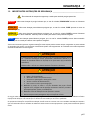
ADJUSTMENTS
ADJUSTMENTS
4.1
GENERAL________________________________________________________________
! WARNING
To prevent injury, depress clutch pedal and shift
transmission to Neutral, engage parking brake, stop
engine, and remove key from ignition switch before
making any adjustments or performing maintenance.
2. Replace, do
components.
not
adjust,
worn,
or
damaged
3. Long hair, jewelry, or loose fitting clothing may get
tangled in moving parts.
! CAUTION
Make sure the vehicle is parked on a solid and level
surface. Never work on a vehicle that is supported
only by the jack. Always use jack stands.
Be careful to prevent entrapment of the hands and
fingers between moving and fixed components of the
machine.
If only the front or rear of the vehicle is raised, place
chocks in front of and behind the wheels that are not
raised.
4. Do not change governor settings or overspeed the
engine.
1. Adjustments and maintenance should always be
performed by a qualified technician. If proper
adjustment cannot be made, contact an authorized
Cushman Dealer.
4.2
5.
Keep hands and feet away from moving parts. If
possible do not make adjustments with the engine
running.
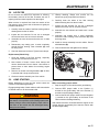
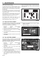
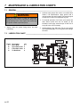
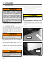
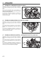
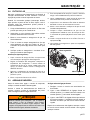
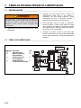
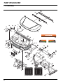
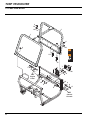
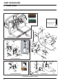
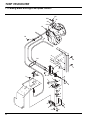
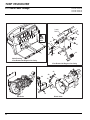
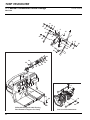
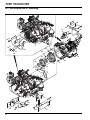
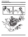
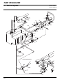
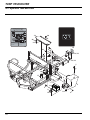
ENGINE ACCESS__________________________________________________________
Never remove or install the engine cover while the engine
is running. The engine cover is a machinery guard and its
removal exposes you to moving parts. Keep hands, hair,
and clothing away from flywheel, radiator cooling fan,
alternator fan, engine belts, pulleys, and air intake.
! WARNING
Keep clothing, hands, and hair away from moving
parts. These items could become entangled, causing
serious personal injury.
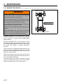
Engine Cover
Latch
For servicing the engine and related components, the
engine cover can be tilted forward or removed.
To gain access to the engine, unlock key-lock if installed,
push the engine cover latch towards the rear of the unit
and tilt cover forward.
Figure 4A
When replacing the engine cover, make sure the
retaining tabs located at the front corners of the engine
cover are inserted into the slots in the floorboard. Tilt seat
to the rear until the engine latch engages. Lock key-lock
if equipped.
! WARNING
Retaining Tab
In Slot On
Floor board
Failure to latch the seat properly can result in the
engine cover tipping forward causing loss of control of
the vehicle and possible personal injury.
Figure 4B
en-12
ADJUSTMENTS
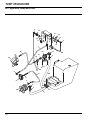
4.3
4
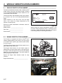
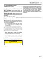
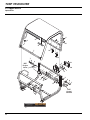
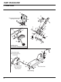
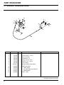
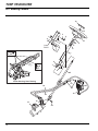
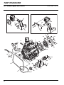
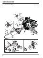
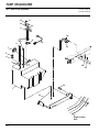
FRONT COWL ACCESS_____________________________________________________
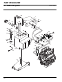
The front cowl opens to gain access to two access
panels, fuse panel, horn, and master cylinder reservoir.
Pull Lever
To Release
Cowl Latc h
To open the front cowl locate the release lever at the
upper left corner of front clip near the left side headlight.
Pull the lever toward the headlight to release the front
cowl latch and at the same time pull up on the front cowl.
Front Cowl
Release Lever
Fully open the cowl and allow it to rest on the steering
wheel (or upper ROPS structure if installed).
The front cowl will not spring up when the release lever is
pulled and so must be lifted manually.
Figure 4C
4.4
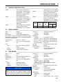
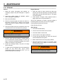
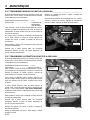
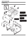
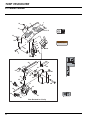
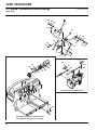
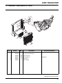
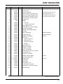
ACCESS PANELS _________________________________________________________
There are two access panels located under the front cowl
and one located in the middle of the floorboard.
Remove panel (A) under cowl to access the shifter
linkage and wiring for the instrument panel.
A
Remove panel (B) under cowl to access the front
suspension.
Remove the center panel (C) in the middle of floorboard
to access the throttle cable, accelerator pedal linkage,
wire harness, and rear hydraulic brake line.
NOTE: It will be necessary to remove the accelerator
pedal in order to completely remove the center floorboard
panel.
B
Figure 4D
C
Figure 4E
en-13
4
ADJUSTMENTS
4.5
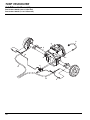
DIESEL ALTERNATOR BELT ________________________________________________
Inspect and adjust new belt after first 24-48 hours of
operation. Adjust every 200 hours thereafter.
Adjust alternator pulley so belt deflects 1/4 to 1/2 in. (6 to
12 mm) with a 20 lb. push at midpoint between water
pump and alternator pulleys.
D
If tension is incorrect loosen alternator mounting bolts (D)
and adjust alternator until proper belt tension is achieved.
Figure 4F
4.6
DIESEL HYDRAULIC PUMP BELT ____________________________________________
Inspect and adjust new belt after first 24-48 hours of
operation. Adjust every 200 hours thereafter.
Adjust hydraulic pump belt so belt deflects 1/4 to 1/2 in.
(6 to 12 mm) with a 20 lb. push at midpoint between
pulleys.
If tension is incorrect loosen pump mounting bolts (E)
and carefully pry pump away from the engine until proper
belt tension is achieved.
E
Figure 4G
4.7
GAS POWER STEERING - ALTERNATOR BELT ________________________________
Inspect and adjust new belt after first 24-48 hours of
operation. Adjust every 200 hours thereafter.
Adjust power steering pump so belt deflects 1/4 to 1/2 in.
(6 to 12 mm) with a 39 lb. push at midpoint between
pulleys.
If tension is incorrect loosen power steering pump
mounting bolts (F) and carefully pry pump away from the
engine until proper belt tension is achieved.
F
Figure 4H
en-14
ADJUSTMENTS
4.8
4
GAS HYDRAULIC PUMP BELT _______________________________________________
Inspect new belt after first 24-48 hours of operation.
Belt is dynamically adjusted with a spring loaded
tensioner to 12 ft-lbs. No adjustment is required.
To remove belt rotate tensioner towards radiator to
release tension and remove belt from pulleys.
Figure 4I
4.9
PARKING BRAKE CABLE ___________________________________________________
1. Remove the engine cover. Put chocks in front of and
behind at least two wheels at opposite corners of
vehicle.
2. Engage parking brake. If handle is at an angle
greater than 45° to the panel, adjustment is
required.
3. Disengage parking brake.
4. Tighten adjustment nut (G) a couple of turns.
5. Engage parking brake. Repeat steps 3 and 4 until
handle is at an approximate 45° angle when parking
brake is engaged.
G
Figure 4J
en-15
4
ADJUSTMENTS
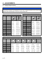
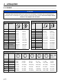
4.10 TORQUE SPECIFICATION___________________________________________________
NOTICE
All torque values included in these charts are approximate and are for reference only. Use of these torque values is
at your sole risk. Cushman is not responsible for any loss, claim, or damage arising from the use of these charts.
Extreme caution should always be used when using any torque value.
Jacobsen uses Grade 5 (Inch) or Grade 8.8 (Metric) bolts as standard, unless otherwise noted.
AMERICAN NATIONAL STANDARD FASTENERS
AMERICAN NATIONAL STANDARD FASTENERS
SIZE
SIZE
UNITS
GRADE 5
GRADE 8
UNITS
GRADE 5
GRADE 8
#6-32
in-lbs (Nm)
20 (2.3)
–
7/16-14
ft-lbs (Nm)
50 (67.8)
65 (88.1)
#8-32
in-lbs (Nm)
24 (2.7)
30 (3.4)
7/16-20
ft-lbs (Nm)
55 (74.6)
70 (94.9)
#10-24
in-lbs (Nm)
35 (4.0)
45 (5.1)
1/2-13
ft-lbs (Nm)
75 (101.7)
100 (135.6)
#10-32
in-lbs (Nm)
40 (4.5)
50 (5.7)
1/2-20
ft-lbs (Nm)
85 (115.3)
110 (149.2)
#12-24
in-lbs (Nm)
50 (5.7)
65 (7.3)
9/16-12
ft-lbs (Nm)
105 (142.4)
135 (183.1)
1/4-20
in-lbs (Nm)
95 (10.7)
125 (14.1)
9/16-18
ft-lbs (Nm)
115 (155.9)
150 (203.4)
1/4-28
in-lbs (Nm)
95 (10.7)
150 (17.0)
5/8-11
ft-lbs (Nm)
150 (203.4)
195 (264.4)
5/16-18
in-lbs (Nm)
200 (22.6)
270 (30.5)
5/8-18
ft-lbs (Nm)
160 (217.0)
210 (284.8)
5/16-24
in-lbs (Nm)
240 (27.1)
300 (33.9)
3/4-10
ft-lbs (Nm)
170 (230.5)
220 (298.3)
3/8-16
ft-lbs (Nm)
30 (40.7)
40 (54.2)
3/4-16
ft-lbs (Nm)
175 (237.3)
225 (305.1)
3/8-24
ft-lbs (Nm)
35 (47.5)
45 (61.0)
7/8-14
ft-lbs (Nm)
300 (406.8)
400 (542.4)
METRIC FASTENERS
SIZE
UNITS
4.8
5.8
8.8
10.9
12.9
Non Critical
Fasteners
into
Aluminum
M4
Nm (in-lbs)
1.2 (11)
1.7 (15)
2.9 (26)
4.1 (36)
5.0 (44)
2.0 (18)
M5
Nm (in-lbs)
2.5 (22)
3.2 (28)
5.8 (51)
8.1 (72)
9.7 (86)
4.0 (35)
M6
Nm (in-lbs)
4.3 (38)
5.7 (50)
9.9 (88)
14.0 (124)
16.5 (146)
6.8 (60)
M8
Nm (in-lbs)
10.5 (93)
13.6 (120)
24.4 (216)
33.9 (300)
40.7 (360)
17.0 (150)
M10
Nm (ft-lbs)
21.7 (16)
27.1 (20)
47.5 (35)
66.4 (49)
81.4 (60)
33.9 (25)
M12
Nm (ft-lbs)
36.6 (27)
47.5 (35)
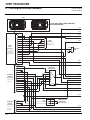
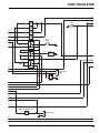
82.7 (61)
116.6 (86)
139.7 (103)
61.0 (45)
M14
Nm (ft-lbs)
58.3 (43)
76.4 (55)
131.5 (97)
184.4 (136)
219.7 (162)
94.9 (70)
en-16
MAINTENANCE
5
5
MAINTENANCE
5.1
GENERAL ________________________________________________________________
lubricated.
! WARNING
Before you clean, adjust, or repair this equipment,
depress clutch pedal and shift transmission to Neutral,
engage parking brake, stop engine, and remove key
from ignition switch to prevent injuries.
Make sure the vehicle is parked on a solid and level
surface. Never work on a vehicle that is supported
only by a jack. Always use jack stands.
1. Adjustment and maintenance should always be
performed by a qualified technician. If proper
adjustments cannot be made contact an Authorized
Cushman Dealer.
2.
Inspect the equipment on a regular basis, establish a
maintenance schedule, and keep detailed records.
5.2
a.
Keep the equipment clean.
b.
Keep all moving parts properly adjusted and
c.
Replace worn or damaged parts before operating
the machine.
d.
Keep all fluids at their proper levels.
e.
Keep shields in place and all hardware securely
fastened.
f.
Keep tires properly inflated.
3.
Long hair, jewelry, or loose fitting clothing may get
tangled in moving parts.
4.
Use the illustrations in the Parts & Maintenance
Manual as reference for the disassembly and
assembly of components.
5.
Recycle or dispose of all hazardous materials
(batteries, fuel, lubricants, anti-freeze, etc.) according
to federal, state, and local regulations.
6.
Keep hands and feet away from moving parts.
Whenever possible do not make adjustments with the
engine running.
ENGINE _________________________________________________________________
IMPORTANT: A separate Engine Manual, prepared by
the engine manufacturer, is supplied with this vehicle.
Read the Engine Manual carefully until you are familiar
with the operation and maintenance of the engine.
Proper attention to the engine manufacturer’s directions
will assure maximum service life of the engine. To order
replacement engine manuals contact the engine
manufacturer.
4. Check and adjust hydraulic pump and alternator
belts. See Sections 4.5, 4.6, 4.7 and 4.8.
The proper break-in of a new engine can make a
considerable difference to the performance and life of the
engine.
Keep your engine clean. If dirt has accumulated on the
engine it should be washed with a nonflammable solvent
or strong detergent.
NOTICE
When washing becomes necessary it can be carried out
concurrent with servicing the vehicle.
The vehicle is designed to operate most efficiently at
the preset governor setting. Do not change the engine
governor settings or overspeed the engine.
During the break-in period Jacobsen recommends the
following:
5. Refer to Section 7.3 and Engine Manual for specific
maintenance intervals.
6. If the injection pump, injectors, or the fuel system
require service contact an authorized Jacobsen
Dealer.
In order to maintain reliable service from your engine a
regular check-up and maintenance schedule should be
followed. Proper maintenance will prolong the engine’s
life and avoid premature overhaul.
1. During the first 50 hours of operation a new engine
should be allowed to reach an operating temperature
of at least 140°F (60°C) prior to operation at full load.
2. Check the engine oil level twice daily during the first
50 hours of operation. Higher than normal oil
consumption is not uncommon during the break-in
period.
3. Change engine oil and oil filter element after first 35
hours of operation.
en-17
5
MAINTENANCE
5.3
ENGINE OIL ______________________________________________________________
Check the engine oil at the start of each day before
starting the engine.
To check the engine oil remove the dipstick and wipe it
with a clean rag. Reinsert the dipstick until it contacts the
oil tube. Remove the dipstick and read the oil level.
Oil Level Must
Be
Between
Marks
Engine
Dipstick
DO NOT OVERFILL
The oil level should always be between the ADD and
FULL mark on the dipstick. If oil level is below the ADD
mark remove the filler cap and add oil to bring the level
up between marks. Do Not Overfill.
NOTE: If the engine has recently been running allow time
(with engine turned off) to let the oil settle to obtain an
accurate oil level reading.
Diesel Engine: Use only
classification CD or CE.
engine
oils
with
Diesel
Engine
ADD
FULL
ADD
API
Gas
Engine
Gas Engine: Use only engine oils with API classification
SJ.
Using oil other than the service class listed or oil change
intervals longer than recommended could reduce engine
life. Damage to engine due to improper maintenance or
use of incorrect oil quality and/or viscosity is not covered
by the engine warranty.
Diesel Engine: Perform initial oil change after first 35
hours of operation and every 75 hours or two months
thereafter. See Engine Manual.
Gas Engine: Perform initial oil change after first 50 hours
of operation and every 100 hours or three months
thereafter. See Engine Manual.
Significant oil loss can damage the engine. Considerable
oil loss could be due to a loose or incorrectly installed
drain plug, cracked gaskets, or a loose oil filter.
Drain plugs are located beneath the engine in the oil pan.
Remove both plugs when changing the oil.
Check drain plugs and oil for metal chips that could
indicate engine damage. Immediately replace drain plugs
with damaged gasket surfaces.
After oil has completely drained clean excess oil from oil
pan and drain plugs. Install drain plugs and tighten
securely. Refer to Engine Manual for proper torque.
Always replace the engine oil filter when changing the
engine oil. Apply a light coat of engine oil to the rubber
gasket surface of new filter before installing.
Diesel Engine: Fill Kubota engine with approximately 5.4
qts. (5.1 l) of clean engine oil. Check oil level and add
additional oil if required.
Gas Engine: Fill Suzuki engine with approximately 3.6
qts. (3.4 l) of clean engine oil. Check oil level and add
additional oil if required.
en-18
FULL
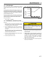
Figure 5A
Kubota Diesel
SAE 10W/10W-30
SAE 20W/10W-30
SAE 30W/10W-30
Suzuki Gas
SAE 10W-30 for all temperature ranges
°F
-20
°C -30
0
-20
20 32 40
-10
0
10W-40
60
10
7780
20 25 30
100
40
Figure 5B
Diesel Engine:
Above 77°F (25°C)
SAE 30W or SAE10W30/10W40
32 to 77°F (0 to 25°C)
SAE 20W or SAE 10W30/10W40
Below 32° (0°C)
SAE10W or SAE 10W30/10W40
Gas Engine:
All
ranges
temperature SAE 10W30
Above 85° F (29° C)
SAE 10W 40
Replacement Oil Filters
Kubota Diesel
4113986
Suzuki Gas
2701908
MAINTENANCE
5.4
5
POWER STEERING RESERVOIR _____________________________________________
! WARNING
Before servicing or doing any maintenance work
around the engine area make sure the engine has had
time to cool. Serious burns can result if the engine or
surrounding surfaces are hot.
When checking the fluid level before the engine has been
warmed up the level should be at the COLD mark on the
dipstick. After the engine has been warmed up and the
fluid is warm the level should be between the COLD and
HOT marks. Use General Motors® Power Steering Fluid
as required to bring fluid up to proper level.
The power steering reservoir is located on the right side
of the engine below the alternator.
HOT
FULL
COLD
ADD
The level in the reservoir should be checked after the first
35 and again at 70 hours. After that the level should be
checked every 100 hours.
Power Steering Dipstick
Figure 5C
5.5
MUFFLER AND EXHAUST___________________________________________________
! WARNING
Exhaust fumes contain carbon monoxide that is toxic
and can be fatal when inhaled.
NEVER operate an engine without proper ventilation.
To protect from carbon monoxide poisoning inspect the
complete exhaust system regularly and always replace a
defective muffler.
If you notice a change in the color or sound of the
exhaust stop the engine immediately. Identify the
problem and have the system repaired.
Torque all exhaust manifold hardware evenly. Tighten or
replace exhaust clamps.
5.6
ENGINE OVERHEAT PROCEDURE ___________________________________________
During vehicle operation if the water temperature gauge
shows 230° F (110° C) or above and/or the overheat
warning buzzer sounds follow this procedure.
1. Stop the vehicle. DO NOT shut the engine off.
Place vehicle in Neutral and engage the parking
brake.
2. Immediately disengage any accessories that are
operating.
3. Slow the engine speed to a fast idle.
4. Remove any dirt, chaff, debris, etc. from the radiator
intake screen located on the right side of the
vehicle.
! CAUTION
Temperature gauge needle should start to go down
approximately 30 seconds after the screen is cleaned. If
temperature does not go down STOP the engine and
check the following:
1. Check to see if cooling fan is operating. Fan should
be turning with coolant above 180° F (82° C) on
diesel units or 208° F (97.7° C) on gas units even
with ignition switch in OFF position.
2. Check engine oil level.
3. Check for a leak in the cooling system. Do not open
radiator when hot. Check coolant levels after system
completely cools.
Failure to heed the overheat warning and properly
maintain the cooling system will cause permanent engine
damage.
Be careful when opening the engine access cover or
cleaning the intake screen. Metal surfaces near the
radiator and engine may be hot to the touch. Use a
brush or gloves to clean screen.
en-19
5
MAINTENANCE
5.7
COOLING SYSTEM ________________________________________________________
This vehicle is equipped with a radiator, temperature
controlled fan, temperature gauge, and an overheat
buzzer.
2. Drain and refill cooling system every 400 hours or 9
months, whichever comes first. Allow system to cool
before draining.
a. Remove the cooling fan fuse
! WARNING
To prevent serious bodily injury from hot coolant or
steam blow-out, never attempt to remove the radiator
cap while the engine is running. Stop the engine and
wait several hours until it is cool. Even then, use
extreme care when removing the cap.
! CAUTION
Do not pour cold water into a hot radiator. Do not
operate engine without a proper coolant mixture.
Install cap and tighten securely.
! WARNING
The cooling fan is controlled by a temperature switch
and may start at any time coolant temperature is
above 150° F (65 ° C), even with the ignition switch in
the OFF position. Do not attempt to service the
cooling system without first disconnecting the
negative battery cable or removing the fan fuse.
NEVER add straight antifreeze to the radiator. Mix equal
amounts of clean water with ethylene glycol based antifreeze in a separate container before adding it to the
cooling system. Do not use a mixture of more than 50%
antifreeze.
Always recycle or dispose of used antifreeze in a
responsible manner. Used antifreeze can be harmful to
the environment.
1. Check coolant level daily. Radiator should be full and
recovery bottle should be up to the cold mark.
a. Tilt engine cover forward to gain access to the
radiator.
b. With the engine stopped and cool, remove
radiator cap and check coolant level. The coolant
level should be at or within 1/4 in. (6 mm) of the
filler port. Fill with a 50/50 antifreeze/water
mixture if required.
c.
en-20
Visually check the reservoir tank. Coolant level
should be at or above FULL line but less than
4 in. (102 mm). Add a 50/50 antifreeze/water
mixture if required.
b. Remove the radiator cap.
c.
Open the engine block drain and the radiator
drain. Remove lower radiator hose. Close both
drains and install lower radiator hose once
system has completely drained.
d. Empty and clean the recovery bottle.
e. Fill radiator to the bottom of the filler neck with
50/50 antifreeze/water mixture.
f.
Fill recovery bottle to full mark with 50/50
antifreeze/water mixture.
3. Keep radiator air passages clean. Use compressed
air (30 psi maximum) to clean the fins. Water left
between the fins will collect dirt and reduce the
amount of air flow to properly cool the engine.
4. To provide proper air flow, do not obstruct the air
intake screen on the right side of the vehicle. Keep
screen clean.
5. Replace clamps and hoses every two years.
6. If you have to add coolant more than once a month,
or add more than one quart at a time, have a
authorized Cushman Dealer check the cooling
system.
MAINTENANCE
5.8
5
AIR FILTER _______________________________________________________________
Do not remove the element for inspection or cleaning.
Unnecessary removal of the filter increases the risk of
injecting dust and other impurities into the engine.
When service is required first clean the outside of the
filter housing, then remove the old element as gently as
possible and discard.
1. Carefully clean the inside of the filter housing without
allowing dust into the air intake.
2. Inspect the new element. Do not use a damaged
element and never use an incorrect element.
3. Assemble the new element and make sure it seats
properly.
4. Reassemble cap making sure it seals completely
around the filter housing. Dust evacuator (A) must
be facing down.
5. Unsnap retaining clamps and remove the old
element as gently as possible and discard.
6. Carefully clean the inside of the filter housing
without allowing dust into the air intake.
7. Inspect the new element. Do not use a damaged
element and never use an incorrect element.
8. Assemble the new element and make sure it seats
properly.
9. Assemble cap making sure it seals completely
around the filter housing. Dust evacuator (A) must
be facing down.
10. Install air cleaner assembly into the vehicle. Secure
with hardware (B).
11. Connect both hoses and tighten hose clamps.
5. Check all hoses and air ducts. Tighten hose clamps.
Gas Engine
Replacement (Diesel Only)
1. Clean the outside of the filter housing, especially
around hose connections and cover.
A
2. Note location of hoses. Loosen hose clamps and
remove both hoses from air cleaner. Use caution to
prevent dust or other debris from entering engine
intake hose.
A
3. Remove air cleaner mounting hardware (B). Air filter
is secured with a single screw and nut.
4. Lift the air cleaner assembly out of the vehicle.
5.9
Diesel Engine
JUMP STARTING __________________________________________________________
Before attempting to jump start the vehicle check the
condition of the discharged battery.
Engage parking brake of both vehicles, shift transmission
to Neutral and turn off all electrical loads.
! WARNING
Batteries generate explosive hydrogen gas. To reduce
the chance of an explosion avoid creating sparks near
battery. Always connect the Negative jumper cable to
the frame of the vehicle with the discharged battery
away from the battery.
When connecting jumper cables:
1. Stop the engine on the vehicle with a good battery.
2. Connect RED jumper cable to the Positive (+)
terminal on the good battery and to the Positive (+)
terminal on the discharged battery.
3. Connect the BLACK jumper cable from the Negative
(-) terminal on the good battery to the frame of the
vehicle with the discharged battery.
After cables have been connected start the engine on the
vehicle with the good battery then start the vehicle with
the discharged battery.
en-21
5
MAINTENANCE
5.10 BATTERY ________________________________________________________________
Make absolutely certain the ignition switch is OFF and
the key has been removed before servicing the battery.
! CAUTION
Always use insulated tools, wear protective glasses or
goggles, and protective clothing when working with
batteries. You must read and obey all battery
manufacturer’s instructions.
Tighten cables securely to battery terminals and apply a
light coat of silicone dielectric grease to terminals and
cable ends to prevent corrosion. Keep vent caps and
terminal covers in place.
Keep the top of the battery clean and free of corrosion by
washing battery with a solution of baking soda and water.
Rinse with clean water.
1. When installing the battery, always assemble the
Positive (RED) (+) battery cable first and the
Negative (BLACK) (-) battery cable last.
2. When removing the battery, always remove the
Negative (BLACK) (-) battery cable first and Positive
(RED) (+) battery cable last.
3. Make sure battery is properly installed and secured
to the battery tray.
! WARNING
Battery posts, terminals, and related accessories
contain lead and lead compounds, chemicals known
to the State of California to cause cancer and
reproductive harm. Wash your hands after
handling.
Verify battery polarity before connecting or disconnecting
the battery cables.
5.11 CHARGING BATTERY _____________________________________________________
! WARNING
Charge battery in a well ventilated area. Batteries
generate explosive gases. To prevent an explosion
keep any device that may create sparks or flames
away from the battery.
To prevent injury stand away from battery when the
charger is turned on. A damaged battery could
explode.
1. Refer to Section 5.10. Read the Battery’s and
Charger’s manuals for specific instructions.
2. Whenever possible remove the battery from the
vehicle before charging. If battery is not sealed
check that the electrolyte covers the plates in all the
cells.
Battery cables must be disconnected before using a fast
charger or damage to the alternator may result.
3. Make sure the charger is Off. Then connect the
charger to the battery terminals as specified in the
charger’s manual.
4. Always turn the charger Off before disconnecting
charger from the battery terminals.
en-22
MAINTENANCE
5
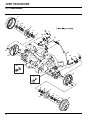
5.12 HYDRAULIC HOSES _______________________________________________________
! WARNING
To prevent serious injury from hot, high pressure oil
never use your hands to check for oil leaks; use paper
or cardboard.
Hydraulic fluid escaping under pressure can have
sufficient force to penetrate skin. If fluid is injected into
the skin it must be surgically removed within a few
hours by a doctor familiar with this form of injury or
gangrene may result.
IMPORTANT: The hydraulic system can be
permanently damaged if the oil becomes
contaminated. Before disconnecting any hydraulic
component clean the area around the fittings and the
hose ends to keep impurities out of the system.
a. Before disconnecting any hydraulic component
tag or mark the location of each hose then clean
the area around the fittings.
b. As you disconnect the component be prepared to
assemble plugs or caps to the hose ends and
open ports. This will keep impurities out of the
hydraulic system and also prevent oil spills.
1. Always disengage all drives, engage parking brake,
stop engine, and remove key before inspecting or
disconnecting hydraulic lines or hoses.
c.
2. Check visible hoses and tubes daily. Look for wet
hoses or oil spots. Replace worn or damaged hoses
and tubes before operating the machine.
d. Keep the hose from twisting. Twisted hoses can
cause couplers to loosen as the hose flexes
during operation resulting in oil leaks.
3. The replacement tube or hoses must be routed in
the same path as the existing hose. Do not move
clamps, brackets, and ties to a new location.
e. Kinked or twisted hoses can restrict the oil flow
causing the system to malfunction, the oil to
overheat and also lead to hose failure.
4. Thoroughly inspect all tubes,
connections every 250 hours.
hoses,
Make sure O-rings are clean and hose fittings
are properly seated before tightening.
and
5.13 HYDRAULIC RESERVOIR AND FILTER ________________________________________
Refer to Section 7.3 for specific maintenance intervals.
To replace hydraulic oil filter:
Normally the hydraulic system will not need additional
fluid. Sometimes a leak may develop causing the system
to require repair and refilling. If you notice hydraulic fluid
escaping when the system is being used or if a leak is
suspected turn off all hydraulic functions and stop
the engine.
1. Remove the old filter.
Periodically check the hydraulic fluid level (hydraulic level
should be checked every 100 hours of operation). Loss
of fluid can signal a small leak before it becomes worse.
4. Check hydraulic oil level and fill with GreensCare 68
to knurled mark on gauge.
2. Fill new filter with GreensCare 68 fluid then install
new filter. Hand tighten only.
3. Operate engine at idle speed with hydraulic system
in Neutral for five minutes.
To check the fluid level:
1. Place vehicle on a flat and level surface. Fully lower
any accessory attachment, including the dump box.
Stop the vehicle engine.
2. Remove the dipstick/breather tube from the top of
the tank. Wipe the dipstick then place in tank with
the threaded flange resting on the tank (do not
screw in). Fluid should show on the knurled portion
of the dipstick. Add GreensCare 68™ fluid as
required.
The hydraulic system is protected by one 10 micron filter.
The filter is located under the side console near the
parking brake lever.
HYDRAULIC
RESERVOIR DIPSTICK
KNURLED PORTION
OF DIPSTICK
SHOWN AS
REFERENCE ONLY
Figure 5E
en-23
5
MAINTENANCE
5.14 FUEL ____________________________________________________________________
Handle fuel with care - it is highly flammable. Use an
approved container. The spout must fit inside the fuel
filler neck. Do not use cans and funnels to transfer fuel.
! WARNING
Remove the fuel cap slowly. Fuel may be under
pressure. Spray could cause serious injury.
Never remove the fuel cap from the fuel tank or add
fuel when the engine is running or while the engine is
hot.
4. Check fuel lines and clamps every 50 hours.
Replace fuel lines and clamps at the first sign of
damage.
5. The fuel tank capacity is 6.5 gal. (24.5 l). Fill tank
using the following fuel recommendations:
Diesel Engine
a. Use clean, fresh, #2 Low or Ultra Low Sulfur
Diesel fuel. Minimum Cetane rating 45. Refer to
Engine Manual for additional information.
Never handle or store fuel containers near an open
flame or any device that may create sparks and ignite
the fuel or fuel vapors.
b. Use clean, fresh, #1 Low or Ultra Low Sulfur
Diesel fuel when operating temperature is below
20° F (-7° C). If #1D fuel is not available a
winterized blend of #1D and #2D may be
available. This blended fuel is usually called #2D
and may be used in colder climates. Do not use
#2D unless you are sure it has been winterized.
Cold temperatures may cause it to thicken which
will keep your vehicle from running properly.
Be sure to reinstall and tighten fuel cap securely.
c.
Do not smoke when handling fuel. Never fill or drain
the fuel tank indoors.
Do not spill fuel and clean spilled fuel immediately.
1. Fill the fuel tank to within 1 in. (25 mm) of the bottom
of the filler neck.
2. Store fuel according to federal, state and local
ordinances and recommendations from your fuel
supplier.
3. Never overfill or allow the tank to become empty.
Check fuel level in the tank by turning the ignition
switch to the ON position and reading the level
indicated by the fuel gauge.
DO NOT use Aviation Fuel JP4. Refer to Engine
Manual for additional information.
Gas Engine: Use clean, fresh Unleaded Gasoline
with 87 octane or higher rating.
NOTICE
The use of any fuel containing greater than 10%
ethanol may harm the engine's emission control
system and therefore invalidate the emission-related
warranty through the improper action of the operator.
5.15 FUEL SYSTEM ____________________________________________________________
Refer to Section 7.3 for specific maintenance intervals.
Before replacing any filter thoroughly clean the filter
housing and the area around the filter. Dirt must not be
allowed to enter into fuel system.
Turn the key switch to the ON position to start the fuel
pump and bleed the fuel system if the fuel filter and lines
have been removed or the fuel tank has become empty.
See Engine Manual.
en-24
MAINTENANCE
5
5.16 TIRE PRESSURE __________________________________________________________
Keep tires properly inflated to prolong tire life. Check
inflation pressure while the tires are cool. Inspect tread
wear.
Lower pressure will help avoid leaving tire marks in soft
turf. Higher pressures may be required for heavier loads.
Rear tire pressure must be set at 28 psi (1.93 BAR) when
operating with a full load. Never exceed the maximum
pressure indicated on the tire.
Check the pressure with an accurate, low pressure tire
gauge. Due to the low volume of air needed over-inflation
may be reached in a matter of two to three seconds.
Rear - Varies, determined by load. (See Chart)
28 (1.93)
23 (1.59)
Rear 18 (1.24)
Tire
Pressure 13 (0.90)
psi
(BAR)
8 (0.55)
Load (Pounds) 0
400
800
1200
Keep tires inflated to:
1500
Figure 5F
Front - 20 psi - (1.38 BAR)
5.17 TIRE REMOVAL AND INSTALLATION _________________________________________
Removal:
1. Park the vehicle on a flat and level surface. Apply
parking brake, shut off engine, and shift transmission
to 1st gear (manual) or Park (automatic).
2. Refer to Section 5.18 for proper lifting procedures.
Always use jack stands. Never rely only on a jack
for support.
Raise the vehicle only enough to remove the tire.
Never place feet, hands, or any part of your body
under the vehicle when raising it.
3. Remove the wheel retaining nuts and remove wheel
and tire assembly from the hub.
4. Perform required service on tire.
! CAUTION
Unless you have the proper training, tools, and
experience, DO NOT attempt to mount a tire on a rim.
Improper mounting can produce an explosion which
may result in serious injury.
Installation:
1. Remove dirt, grease, and oil from stud thread. Do not
lubricate threads.
2. Position wheel on hub and inspect to ensure full
contact between mounting surface of wheel and hub
or brake drum. Make sure valve stem is located
towards the outside. Finger tighten all hardware
then torque hardware in criss-cross order. Always
tighten nuts in the top position.
3. Check and retorque daily until 70-100 ft lbs (95-140
Nm) torque is maintained.
en-25
5
MAINTENANCE
5.18 RAISING THE VEHICLE_____________________________________________________
! WARNING
Block Tire Here
Make sure the vehicle is parked on a solid and level
surface. Never work on a vehicle that is supported
only by a jack. Always use jack stands.
Whenever possible empty the truck bed before raising
the vehicle. Loads moving inside the bed can cause
an unbalanced load that could tip the vehicle.
Never raise the vehicle with the engine running or with
a person sitting in the operator’s seat.
- Jacking Location
Always block the tire diagonally opposite the tire being
raised.
Never place hands, feet, or any part of your body
under the vehicle when raising it with a hoist or if
vehicle is not properly supported by jack stands.
A scissors type jack or a floor jack with a 1-1/2 ton
(minimum) capacity that can be lowered to a height of
3-3/8 in. (86 mm) is required. Refer to Figure 5G for
jacking locations.
Shift the transmission into 1st gear (manual) or Park
(automatic) and apply the parking brake. Chock or block
the tire diagonally opposite the side being raised. Raise
the vehicle only enough to perform maintenance
required.
Jack the vehicle to an appropriate height and place jack
stands or equivalent support beneath the frame near the
jack. Lower the jack and allow the vehicle to rest on jack
stands. Do not remove jack.
When using a hoist to raise the vehicle use the same
procedure for supporting the frame and blocking the tires
as you would when using a jack.
To prevent damage to the vehicle or attached accessory
never use a hoist to raise only one corner of the vehicle.
Always raise BOTH front or rear corners equally.
en-26
If Using Jack Here
Figure 5G
MAINTENANCE
5
5.19 TOWING THE VEHICLE _____________________________________________________
! WARNING
To prevent injury or vehicle damage the following
guidelines should always be followed.
• Never accelerate or stop suddenly when towing
a vehicle.
4. Slowly drive towing vehicle forward until tow-line is
pulled tight.
5. While towing, try to keep the tow-line taught at all
times. Be careful going down inclines and turning
corners.
Tow Line Attachment
• Never change the direction of the vehicle
abruptly or make sharp turns on an incline
when towing a vehicle.
• Never tow the vehicle faster than 5 mph (8 km/
h). Towing at excessive speed could cause
either vehicle to lose proper steering control.
• Adjust your speed for weather and surface
conditions (rain, snow, ice, hills, etc.) when
towing.
• Use care when loading or unloading machine
onto a trailer or truck.
If for any reason the vehicle needs to be towed follow the
procedures below:
1. If towing the vehicle with a tow-rope or chain an
operator is required to steer the towed vehicle and to
control the brakes.
A Front Bumper Accessory (Part No. 894778)
is available for use with the Truckster. If a
Front Bumper is mounted to your vehicle,
make sure to follow the instructions included
with the bumper for proper connection of the
chain or tow rope.
2. Attach a tow-rope to the front vertical frame member
on either side of the vehicle only.
Figure 5H
3. Shift transmission into Neutral and release parking
brake.
5.20 GOVERNOR OIL LEVEL ____________________________________________________
Suzuki Gas Engine only.
Check the oil level in the governor every 100 hours of
use. Check only when engine is cool. To check the level
remove the plug from the back side of the governor. Oil
level should be up to the level of the plug opening.
Governor Oil
Fill Plug
Governor Oil Capacity . . . . . . .1.5 oz. (44 me)
Oil Type . . . . . . . . . . . . . . . . . . .SAE 20W engine oil
If fluid level is low add the recommended oil type.
Remove the plug from the rear of the governor and
remove the plug from the top of the governor. Add SAE
20W motor oil until the oil begins to leak from the rear
port. Replace both plugs.
When replacing the plugs use Teflon® tape or a
Permatex® 20 sealant (or equivalent pipe thread sealant)
on the threads of the plug.
Governor Oil
Level Check Plug
Figure 5I
Torque the plugs to 95 ±10 in lb (10.7± 1 Nm).
en-27
5
MAINTENANCE
5.21 HYDRAULIC BRAKES ______________________________________________________
4. Repeat Step 3 for each brake.
! WARNING
Improper maintenance of the brake system may result
in loss of vehicle control by the operator. Losing
control of the vehicle due to brake loss may cause
injury to the operator or bystanders and vehicle
damage.
5. Most communities have a disposal system for DOT
3 brake fluid. Please dispose of fluids properly.
Brake Fluid
Reser vo ir
This vehicle is equipped with four-wheel hydraulic brakes
controlled by the brake pedal and a hand operated
parking brake lever.
Keep your brake system clean and properly maintained.
Do not operate the truck if the brakes do not stop vehicle
properly.
Figure 5J
The brake fluid master cylinder reservoir is located under
the front cowl.
The fluid level in the master cylinder reservoir must be
kept between the MIN (minimum) and MAX (maximum)
marks. Add DOT 3 type brake fluid as necessary.
Fluid Level
If the brake fluid indicator light comes on and remains on
check the fluid level in the reservoir.
Bleeding Hydraulic Brakes:
If the brakes do not hold properly, if they feel spongy, or if
the brake fluid reservoir is allowed to run dry it may be
required to bleed the system in order to remove air from
the brake lines.
Figure 5K
1. Bleed the brakes in the following order: Left Rear,
Right Rear, Right Front and Left Front.
2. Attach a hose to the bleeder screw and place the
other end of the hose in a container to catch fluid
from brake when bleeding the system.
Brake Fluid Lever
Indic ator Light
3. Bleed brake.
a.
Have an assistant push down on the brake pedal
and hold the pedal down.
b.
Loosen the bleeder screw allowing fluid to flow.
c.
Tighten the bleeder screw.
d.
Have assistant release pedal.
Figure 5L
NOTE: Do Not release brake pedal until the bleeder
screw is tightened or air will be sucked back into the
brake lines.
e.
Repeat Steps a through d as required until all air
bubbles are purged from the system and a steady
flow of fluid comes from the brake line.
f.
Periodically check fluid level in reservoir. Do not
allow the reservoir to fully empty or bleeding
procedure will need to be repeated.
en-28
Bleeder
Screw
Figure 5M
MAINTENANCE
5
5.22 DIFFERENTIAL FLUID ______________________________________________________
The differential fluid should be checked every 100 hours
or 3 months. Fluid should be changed after the first 100
hours and every 600 hours (or yearly) thereafter.
Differential Fluid Capacity ...... 3 qts (2.84 l)
Fluid Type .............................. SAE EP 80-90 gear lube
Level Check And
Fill Plug
To check differential fluid level remove the filler plug from
the front of the differential. Fluid should be level with the
bottom of filler hole.
If fluid is low add gear lube until fluid begins to leak from
hole. Apply pipe thread sealant and install filler plug.
To change differential fluid remove drain plug from rear of
differential.
Allow fluid to drain into a suitable container. Dispose of
used fluid properly according to federal, state, and local
regulations.
Figure 5N
Apply pipe thread sealer to drain plug and install.
Fill differential with gear lube until fluid begins to leak
from hole. Apply pipe thread sealant and install filler plug.
Drain Plug
Figure 5O
5.23 DIESEL ENGINE MANUAL TRANSMISSION ____________________________________
The transmission fluid should be checked every 100
hours or 3 months. Fluid should be changed every 600
hours (or yearly).
Transmission Fluid Capacity .. 1.35 qts (1.28 l)
Fluid Type .............................. SAE EP 80-90 gear lube
To check transmission fluid level remove the filler plug
from the front of the transmission. Fluid should be level
with the bottom of filler hole.
Level Check And
Filler Plug
Transmi ssi on
Drain Plug
If fluid is low add gear lube until fluid begins to leak from
hole. Apply pipe thread sealant and install filler plug.
To change fluid remove drain plug from rear of
transmission.
Allow fluid to drain into a suitable container. Dispose of
used fluid properly according to federal, state, and local
regulations.
Figure 5P
Apply pipe thread sealer to drain plug and install.
Fill transmission with gear lube until fluid begins to leak
from hole. Apply pipe thread sealant and install filler plug.
en-29
5
MAINTENANCE
5.24 GAS ENGINE MANUAL TRANSMISSION_______________________________________
The transmission fluid should be checked every 100
hours or 3 months. Fluid should be changed every 600
hours (or yearly).
Fill transmission with gear lube until fluid begins to leak
from hole. Apply pipe thread sealant and install filler plug.
Transmission Fluid Capacity .. 1.1 qts (1 l)
Fluid Type .............................. SAE EP 80-90 gear lube
To check transmission fluid level remove the filler plug
from the front of the transmission. Fluid should be level
with the bottom of filler hole.
Fill Plug
If fluid is low add gear lube until fluid begins to leak from
hole. Apply pipe thread sealant and install filler plug.
To change fluid remove drain plug from rear of
transmission.
Drain
Plug
Allow fluid to drain into a suitable container. Dispose of
used fluid properly according to federal, state, and local
regulations.
Apply pipe thread sealer to drain plug and install.
Figure 5Q
Fill transmission with gear lube until fluid begins to leak
from hole. Apply pipe thread sealant and install filler plug
5.25 GAS ENGINE AUTOMATIC TRANSMISSION ____________________________________
The transmission fluid should be checked every 100
hours or 3 months. Fluid should be changed every 600
hours (or yearly).
Transmission Fluid Capacity .. 3.8 qts (3.6 l)
Fluid Type ............................. Mercon/Dextron II
To check transmission fluid level the engine must be
running. Place the gear selector in Park (P), apply the
parking brake and start the engine.
Transmission
Fluid Dipstick
and Fill Tube
With engine running remove the dipstick and wipe it with
a clean rag. Insert the dipstick into the extension tube
until it contacts the tube. Remove the dipstick and read
the fluid level.
Fluid must be kept between the two marks on the
dipstick. If fluid is low add fluid to obtain the proper level.
Do Not Overfill. Add fluid using the extension tube as a
fill tube.
To change fluid remove drain plug from bottom of
transmission.
Drain Plug
Automatic Transmission
Allow fluid to drain into a suitable container. Dispose of
used fluid properly according to federal, state, and local
regulations.
Apply pipe thread sealer to drain plug and install.
Fill transmission until fluid reaches proper mark on
dipstick.
Figure 5R
en-30
MAINTENANCE
5
5.26 ELECTRICAL SYSTEM _____________________________________________________
! CAUTION
Always turn the ignition switch to the OFF position and
remove the Negative (BLACK) battery cable before
inspecting or working on the electrical system.
General precautions that can be taken to reduce
electrical problems are listed below:
Diesel Engine
Power Port 15 A
Brake Light,
5th Wheel Brake 10 A
If the Interlock System does not function properly and
the problem cannot be corrected contact an
authorized Jacobson Dealer.
3. Keep the wire harness and all individual wires away
from moving parts to prevent damage.
4. Check the battery and battery charging circuit.
5. Do not wash or pressure spray around electrical
connections and components.
6. Circuits are protected by fuses located under the
front cowl and a fuse located near the cooling fan.
10 A Accessary
Flashers & 10 A
Horn
10 A Heater
Accessary
Headlights 15 A
10 A Wiper,
Dome Light &
Back-Up Alarm
1. Ensure all terminals and connections are clean and
properly secured.
2. Check the Interlock System and fuses regularly.
20 A Dash Panel,
Fuel Pump
& Ignition
Gas Engine
Accessary 10 A
Dash Panel,
ECU, Fuel
20 A & Engine Coils
Power Port 15 A
25 A Radiator
Fan
Headlights 15 A
15 A ECU, Main Relay,
Injectors
Brake Light,
5th Wheel Brake 10 A
Flashers & 10 A
Horn
Heater 10 A
Accessary
10 A Backup Alarm
Shift Switch
10 A ECU
10 A Wiper,
Dome Light &
Back-Up Alarm
Figure 5S
5.27 DASH PANEL _____________________________________________________________
The dash panel contains gauges and instrument lights to
display unit functions. Maintenance of the panel is limited
to replacing bulbs and setting the DIP switches.
Remove the four screws securing the instrument panel to
the dash.
Pull panel out, tilt panel forward and disconnect electrical
connector for easier access to rear of panel.
K
L
M
N
Right Turn........................... C161
Parking Brake ..................... C161
High Beam.......................... C658
Alternator / Battery ............. C161
4. Place bulb and holder back into panel. Turn holder
1/4 turn clockwise to secure into panel. Ensure base
of holder is properly seated in panel.
Light Bulb Replacement:
1. Determine which bulb needs to be replaced.
2. Rotate bulb holder 1/4 turn counter-clockwise and
pull up and away from dash panel.
3. Replace old bulb with a new bulb of equal type.
Location ........................... Replacement Bulb
A Voltmeter.............................C658
B Temperature Gauge............C658
C Fuel Gage ...........................C658
D Hour Meter..........................C658
E Tachometer .........................C161
F Left Turn Signal...................C161
G Oil Pressure ........................C161
H Glow Plug ...........................C161
J Brake Fluid..........................C161
en-31
5
MAINTENANCE
Tachometer DIP Switch Setting:
The dash panel uses a DIP Switch sequence code to
identify the number of input pulses per engine revolution
and engine type to correctly display the engine RPM on
the tachometer.
If you are replacing the dash panel or if the tachometer is
not operating correctly check to be sure the sequence
code is set correctly.
Using a small blade screwdriver or similar tool push the
switch levers either up or down to match the sequence
code for this unit.
Diesel Engine Setting
1
0
The Truckster with a Kubota Diesel engine uses the
following sequence code for 10.5 pulses / revolution.
K
Kubota Diesel Sequence Code: 0 0 0 1 0 1 0 0
L
The Truckster with a Suzuki Gas engine uses the
following sequence code for 1.5 pulses / revolution.
M
Gas Engine Setting
1
0
E
B
F
G
C
A
D
H
J
Suzuki Gas Sequence Code: 0 0 0 0 0 0 1 0
Figure 5T
5.28 HEADLIGHT REPLACEMENT ________________________________________________
The headlight should be replaced as soon as it stops
functioning or is damaged. The headlight is a sealed unit
and can only be replaced as a complete unit.
Description ................ bulb type
Headlight................... H6545
5. Remove the headlight from the bezel. Properly
dispose of old bulb.
6. Install new headlight in reverse order of removal.
Jacobson Part No.
837303
1. Disconnect the Negative (BLACK) battery cable.
2. Remove the four screws securing the headlight
bezel to the front cowl.
Headlight
Bezel
3. Pull headlight and bezel forward and out of the front
clip opening.
4. Disconnect the electrical connector from the rear of
the headlight.
Remove The Four (4) Screws
For Headlight Removal
Figure 5U
5.29 TAIL LIGHT REPLACEMENT_________________________________________________
The tail light should be repaired as soon as it stops
functioning or is damaged. The tail light bulb and lens are
replaceable components. Damage to the body of the tail
light requires a complete replacement.
Description ................ bulb type
Tail light bulb ............. 1157
Jacobson Part No.
822049
1. Remove the two screws securing lens. Remove lens
and gasket.
2. Push bulb in, turn 1/4 turn and remove bulb.
Dispose of old bulb properly.
3. Install new bulb in reverse order of removal. Ensure
lens gasket is properly positioned.
4. To remove complete tail light assembly remove two
nuts and shake proof washer securing tail light to
frame. Disconnect harness and remove tail light
from frame.
en-32
Remo ve The Two (2)
Screws For Bulb
Or Lens Replacemen t
Figure 5V
MAINTENANCE
5
5.30 EFI DIAGNOSTIC CHECK ___________________________________________________
Suzuki Gas Engine units only
The electrical system is equipped with an OBD-II
diagnostic connector.
Manual transmission: Engage parking brake, shift
transmission to Neutral, and turn the ignition switch to the
OFF position.
Open the front cowl and locate the OBD-II connector on
the brake fluid reservoir bracket. Plug an OBD-II reader
into the connector, turn ignition switch to the ON position
(do not start engine), and refer to the instructions
included with the reader to retrieve diagnostic codes.
Refer to the Truckster Technical Repair Manual for code
descriptions.
Automatic Transmission: Engage parking brake, place
gear selector in Park, and turn the ignition switch to the
OFF position.
5.31 CARE AND CLEANING _____________________________________________________
Wash the vehicle after each use. Keep the equipment
clean.
Note: Do not wash any portion of the equipment while it
is hot. Do not use high pressure spray or steam. Use cold
water and automotive cleaners.
1. Use compressed air to clean engine and radiator
fins. A special blow gun is available through
Cushman Dealer.
2. Use only fresh water for cleaning your equipment.
Note: Use of salt water or affluent water has been known
to encourage rust and corrosion of metal parts resulting
in premature deterioration or failure. Damage of this
nature is not covered by the factory warranty.
3. Do not spray water directly at the dash panel,
ignition switch, controls, or any other electrical
components, or at bearing housings and seals.
4. Clean all plastic or rubber trim with a mild soap
solution or use commercially available vinyl/rubber
cleaners.
Repair damaged metal surfaces and use touch-up paint.
Wax the equipment for maximum paint protection.
! CAUTION
Clean grass and debris from drives, muffler, and
engine to prevent fires.
en-33
5
MAINTENANCE
5.32 STORAGE________________________________________________________________
General
Engine (General)
1. Wash the vehicle thoroughly and lubricate as
necessary. Repair and paint damaged or exposed
metal.
1. While the engine is warm remove the drain plug,
drain the oil from the crankcase, and change oil filter.
Install drain plug and refill with fresh oil. Let engine
cool before storing.
2. Inspect the vehicle, tighten all hardware, replace
worn or damaged components.
3. Drain and refill radiator.
4. Clean the tires thoroughly and store the vehicle so
the load is off the tires. If vehicle is not on jack
stands check tires at regular intervals and reinflate
as necessary.
5. Keep the machine and all its accessories clean, dry
and protected from the elements during storage.
2. Clean exterior of engine. Paint exposed metal or
apply a light coat of rust preventative oil.
Add a fuel conditioner or biocide to prevent gelling or
bacterial growth in fuel. See your local fuel supplier.
If storing indoors drain fuel from tank.
Close fuel shut off valve.
After Storage
1. Check and reinstall battery.
! WARNING
Never store equipment near an open flame or spark
which could ignite fuel or fuel vapors.
Battery
1. Remove, clean and store battery in upright position
on a nonconductive surface (wood) in a cool, dry
place. To prevent accelerated discharge do not store
battery on concrete or steel surface.
2. Check and recharge battery every 60 to 90 days
while in storage.
3. To reduce the self discharge rate room temperature
should not rise above 80°F (27°C). Room
temperature should not fall below 20°F (-7°C) to
prevent electrolyte from freezing.
en-34
2. Check or service fuel filter and air cleaner.
3. Check the radiator coolant level.
4. Check oil level in the engine crankcase.
5. Fill the fuel tank with fresh fuel. Open fuel shut off
valve and bleed the fuel system.
6. Make certain that the tires are properly inflated.
7.
Start and operate the engine at 1/2 throttle. Allow
sufficient time for the engine to become properly
warmed and lubricated.
! WARNING
Never operate the engine without proper ventilation.
Exhaust fumes can be fatal when inhaled.
TROUBLESHOOTING
6
6
TROUBLESHOOTING
6.1
GENERAL ________________________________________________________________
The troubleshooting chart below lists basic problems that
may occur during start up and operation. For more
detailed information regarding the electrical system
contact your area Jacobson Dealer.
Symptoms
Possible Causes
Action
Engine will not start.
1. Clutch pedal not depressed.
1. Check start up procedure.
2. Battery low on charge or
defective.
2. Inspect condition of battery and battery
connections.
3. Fuel tank empty or dirty. Fuel
shut off valve closed.
3. Fill with fresh fuel. Change fuel filter. Bleed fuel
lines. Open fuel shut off valve.
4. Fuse blown.
4. Replace fuse.
Engine hard to start or 1. Fuel level low. Fuel or fuel filter 1. Fill with fresh fuel. Change fuel filter. Bleed fuel
runs poorly.
dirty.
lines.
2. Air cleaner dirty.
2. Inspect and replace air filter.
3. Injectors, fuel pump.
3. Consult engine manual.
4. Engine problem.
4. Consult engine manual.
Engine stops.
1. Fuel tank empty.
1. Fill with fresh fuel and bleed fuel lines.
Engine overheating.
1. Coolant level low.
1. Inspect and add coolant.
2. Air intake restricted.
2. Clean cooling air intake.
3. Water pump belt broken or
loose.
3. Replace or tighten belt.
4. Engine overload.
4. Reduce forward speed.
Vehicle does not react 1. Parking brake engaged.
to throttle pedal.
2. Transmission in Neutral.
3. Clutch Pedal Depressed.
Disengage parking brake.
Depress brake and clutch pedals. Shift to proper gear
for desired ground speed. Release brake pedal.
Slowly let out clutch while pressing the throttle pedal.
Slowly let out clutch pedal.
en-35
7
MAINTENANCE & LUBRICATION CHARTS
7
MAINTENANCE & LUBRICATION CHARTS
7.1
GENERAL________________________________________________________________
! WARNING
Before you clean, adjust, or repair this equipment,
disengage all drives, lower implements to the ground,
engage parking brake, stop engine and remove key
from ignition switch to prevent injuries
1. Always clean the grease fitting before and after
lubricating.
7.2
2. Lubricate with grease that meets or exceeds NLGI
Grade 2 LB specifications. Apply grease with a
manual grease gun and fill slowly until grease begins
to seep out. Do not use compressed air guns.
3. For smooth operation of all levers, pivot points and
other friction points that are not shown on the
lubrication chart apply several drops of SAE 30 oil
every 40 hours or as necessary.
4. Grease fittings every 100 hours. Do not over grease
drive shaft fittings (A). Too much grease will damage
the seals.
LUBRICATION CHART _____________________________________________________
Brake Fluid
Reservoir
Fitting
A
B
C
D
Description
Drive Shaft
Upper Ball Joints
Lower Ball Joints
Tie Rod Ends
Qty
2
2
2
4
A
D
Fuse Box
C
D
C
B
en-36
MAINTENANCE & LUBRICATION CHARTS
7.3
7
MAINTENANCE CHARTS____________________________________________________
Recommended Service and Lubrication Intervals
Daily
Air Filter
Alternator
Battery
Belts
Brake Fluid
Brake Linings
Clutch
Cooling System
Differential Fluid
Electrical System
Engine Glow Plugs
Engine Idle Speed
Engine Noise / Vibration
Engine Oil (Suzuki)
Engine Oil Filter (Suzuki)
Engine Oil (Kubota)
Engine Oil Filter (Kubota)
Engine Valve Clearance
Fluid Leaks
Fuel System
Fuel Filter
Fuel Water Separator
(Diesel Only)
Governor Fluid
Hydraulic Filter
Hydraulic Fluid
Injection Pump / Timing
Lubricate Chassis
Muffler and Exhaust
Radiator Screens
Power Steering Fluid
Spark Plugs (Gas only)
Starter Motor Brushes
Tires
Transmission Fluid
(Manual Transmission)
Transmission Fluid
(Automatic Transmission)
Wheel Bearings
A - Add or Adjust
First
35
Hours
Every
75
Hours or
2 Months
Every
100
Hours or
3 Months
Every
200
Hours or
6 Months
Every 400
Hours or
9 Months
Every
600
Hours or 12
Months
R**
See
Section
Lubricant
Type
5.8
I
I
I-A*
I-A
C
5.10
I-A
4., 4.2
I-A
I-A*
I-A
5.21
VI
5.7
IV
5.22
III
I-A
I-A
I-C-A
I
R
I-R*
I*
R
I
5.26
I
I*
I
I
I
R*****
I
R*****
I
R*
R**
R*
R**
I
R**
5.3
R**
5.3
5.3
II
5.3
I****
I****
I-R
I*
I
R
5.15
5.15
I-C
I-A
IX
R
I-A
R
L
L
VIII
I
I
I
7.2
I
5.5
I-C/AR
5.7
I*
I
5.4
V
C-A-R
I
I
I-A
5.16
I
R
5.23
5.24
III
I
R
5.25
VII
Repack
C - Clean
I - Inspect
L- Lubricate
R - Repair or Replace
AR - As Required
en-37
7
MAINTENANCE & LUBRICATION CHARTS
Notes:
* Indicates initial service for new machines.
** Engine oil, oil filter and air filter may require more
frequent replacement
depending on operating
conditions.
*** Inspect visible hoses and tubes for leaks or oil
marks.
**** Must be done at Authorized Dealer.
***** Change oil and filter on Suzuki Engines after first
fifty hours.
7.4
Lubricants
I Manual grease gun with NLGI Grade 2 (Service
Class LB).
II Engine Oil - See Section 5.3
III SAE EP 80-90 gear lube
IV Capacity: 3qt. (2.8 l) 50/50 water ethylene glycol mix
V GM Power Steering Fluid
VI DOT 3 brake fluid
VII Mercon/Dextron II automatic transmission fluid
VIIIGreensCare 68 hydraulic fluid
5003102 55-gallon drum GreensCare 68
5003103 5-gallon pail GreensCare 68
IX SAE 20W oil
COMMON REPLACEMENT PARTS ___________________________________________
Part Number
7.5
Part Description
Part Number
Part Description
5000919
Diesel Air Filter Element
4140919
840352
Gas Air Filter Element
4139265
4113986
Diesel Oil Filter
Gas Alternator - Power Steering Belt
2701809
Gas Oil Filter
4139351
Gas Hydraulic Pump Belt
4183591
Diesel Fuel Filter
2701898
4119606
Gas Fuel Filter
NGK 3932 (DCPR7E) Spark
Plug
4175560
Diesel Alternator Belt
2701832
4117092
Denso XU22EPR-U Spark
Plug
Diesel Hydraulic Pump Belt
Gas Water Pump Belt
KUBOTA DIESEL ENGINE SERVICE PARTS ___________________________________
The following common engine parts are provided for reference only. Refer to the Engine Parts Manual for a complete
list of service parts.
Part Number
Part Description
Part Number
Part Description
Fuel Solenoid
2809955
Oil Fill Cap Seal
Injection Pump
2500856
Valve Cover Gasket
Injection Pipe #1
557888
Starter Motor
5000902
Injection Pipe #2
4183623
Alternator
5000903
Injection Pipe #3
4183586
Fuel Injector
5001265
Injector Return Pipe
4177227
Glow Plug
556412
Thermostat
4134370
Thermostat Gasket
4165525
Water Pump
557867
Water Pump Gasket
4177260
Oil Pan Drain Plug
2500811
Oil Pan Drain Plug Gasket
4113986
Oil Filter
4145944
Oil Fill Cap
2811021
5000894
5000901
en-38
NOTES
8
8
NOTES
en-39
9
9
PARTS CATALOG
PARTS CATALOG
9.1
HOW TO USE THE PARTS CATALOG _________________________________________
Abbreviations
Indented Items
N/S - Not serviced separately. Can only be
obtained by ordering main component or kit.
AR -Variable quantity or measurement is required
to obtain correct adjustment.
Symbols such as ● next to the item number
indicates that a note exists which contains
additional information important in ordering that
part.
Indented items indicate component parts that are
included as part of an assembly or another component.
These parts can be ordered separately or as part of the
main component.
Item
●
9.2
Part No.
1
2
3
4
5
123456
789012
345678
N/S
901234
Qty
Description
1
1
1
1
1
Mount, Valve
Valve, Lift
• Handle
• Seal Kit
Screw, 1/4-20 x 2” Hex Head
Serial Numbers/Notes
Indicates a piece part
Includes Items 2, and 3
Serviced part included with Item 2
Non serviced part included with Item 2
TO ORDER PARTS_________________________________________________________
1. Write your full name and complete address on the
order.
5. Send or bring the order to an authorized Jacobsen
Distributor.
2. Explain where and how to make shipment.
6. Inspect all shipments on receipt. If any parts are damaged or missing file a claim with the carrier before
accepting.
3. Give product number, name and serial number that is
stamped on the name plate or serial plate of your
product.
4. Order by the quantity desired, the part number and
description of the part as given in the parts list.
7. Do not return material without a letter of explanation
listing the parts being returned. Transportation
charges must be prepaid.
Use of other than Jacobsen authorized parts will void the warranty.
en-40
INTRODUÇÃO
Este manual contém instruções de segurança,
funcionamento, ajuste, manutenção, resolução de
problemas e lista de peças para a sua nova máquina
Cushman. Este manual deve ser guardado com o
equipamento, para consulta durante o funcionamento.
A chapa com o número de série está localizada na calha do
chassis por baixo do volante. Cushman recomenda que
tome nota desses números abaixo para facilitar a
referência.
CHARLOTTE, NC, USA
1 800 848 1636
Jacobsen.com
Antes de trabalhar com a máquina de cortar relva, o
proprietário e cada operador devem ler o manual
cuidadosamente por inteiro. Seguindo as instruções de
segurança, funcionamento e manutenção, prolongará a
longevidade do equipamento e manterá a sua máxima
eficácia.
MODEL
xxxxx
DATE CODE
xxxxx
LABEL # xxxxxxxx
SERIAL #
*xxxxxxxx*
Lb/kg W Batt
Nom Power Hp/kw
Se for necessária informação adicional, contacte o seu
vendedor Cushman.
Sugestão para stock de peças
Para manter o seu equipamento inteiramente operacional e a dar bom rendimento, a Jacobsen sugere a manutenção de um
stock com os materiais de manutenção mais vulgarmente usados. Incluímos números de peças para materiais adicionais de
apoio e ajudas para treino.
Para encomendar qualquer do material seguinte:
1. Escreva o seu nome e endereço completos na sua nota
da encomenda.
2. Descreva onde e como deve ser feito o embarque:
q UPS
q Correio normal
q Correio azul
q 2º dia
3. Encomende as quantidades pretendidas, pelo número e
pela descrição da peça.
4. Envie ou entregue o pedido ao seu vendedor autorizado
Jacobsen.
Peças de assistência técnica
Qt.
Peça
Descrição
Qt.
4113986 Filtro de óleo de motor Diesel
550489 Elemento do filtro de gasóleo
Correia da direcção assistida - alternador
4175560
do motor Diesel
Correia da bomba hidráulica do motor
4117092
Diesel
5000919 Elemento do filtro de ar de motor Diesel
Peça
Descrição
2701908 Filtro de óleo de motor a gasolina
2701898 Filtro de gasolina
Correia da direcção assistida - alternador do
4139265
motor a gasolina
Ccorreia da bomba hidráulica - Controlador
4235370
de velocidade do motor a gasolina
840352 Elemento do filtro de ar do motor a gasolina
885249 Elemento do filtro do óleo hidráulico
Material de apoio de serviço
Qt.
Peça
4241725
4241724
4160162
4241728
Material para apoio da assistência
Manual de Segurança e Funcionamento
Peças e Manutenção
Manual de Peças do Motor Kubota D1105
Manual de Peças do Motor Suzuki K6A
Qt.
Peça
4171642
4171675
4171985
4239442
2006/42/EC
A seguir são apresentadas as traduções das instruções originais
verificadas pela ACMTRAD SL.
© Copyright 2011, Jacobsen, A Textron Company. “Reservados todos
os direitos, incluindo o de reprodução deste livro ou de partes suas”
pt-2
Litho nos EUA 1-2011
Descrição
Manual de Assistência do Veículo MT
Manual de Assistência do Veículo AT
Manual de Assistência de Suzuki K6A
Manual de acessórios
Aviso - Proposta 65
Este produto contém ou emite produtos
químicos reconhecidos pelo Estado da
Califórnia por provocarem cancro e
anomalias de nascença ou outros
perigos a nível da gestação.
Índice
1
1.1
1.2
SEGURANÇA
Segurança no funcionamento............................. 4
Importantes instruções de segurança ................. 5
2
2.1
2.2
NÚMEROS DE IDENTIFICAÇÃO DO VEÍCULO
Número de identificação do veículo.................... 6
Números de identificação do motor .................... 6
3
3.1
3.2
3.3
3.4
3.5
3.6
3.7
3.8
ESPECIFICAÇÕES
Identificação do produto ..................................... 7
Motor a Diesel ..................................................... 7
Motor a Gasolina ................................................. 7
Veículo ................................................................ 8
Relações de transmissão ................................... 8
Pesos e dimensões ............................................ 8
Acessórios e literatura de apoio ......................... 9
Declaração de Conformidade ............................ 10
4
4.1
4.2
4.3
4.4
4.5
4.6
AFINAÇÕES
Generalidades .................................................. 12
Acesso ao motor ............................................... 12
Acesso ao painel dianteiro ................................ 13
Painéis de acesso ............................................. 13
Correia do alternador do motor a diesel ........... 14
Correia da bomba hidráulica do
motor a diesel ................................................... 14
4.7 Correia da direcção assistida –
alternador do motor a gasolina ......................... 14
4.8 Correia da bomba hidráulica do
motor a gasolina ............................................... 15
4.9 Cabo do travão de estacionamento .................. 15
4.10 Binário ............................................................... 16
5
5.1
5.2
5.3
5.4
5.5
5.6
5.7
5.8
5.9
MANUTENÇÃO
Generalidades .................................................. 17
Motor ................................................................. 17
Óleo de motor ................................................... 18
Reservatório da direcção assistida ................... 19
Tubo e panela de escape ................................. 19
Procedimento no sobreaquecimento
do motor ............................................................ 19
Sistema de arrefecimento ................................. 20
Filtro do ar ......................................................... 21
Arranque induzido ............................................. 21
5.10
5.11
5.12
5.13
5.14
5.15
5.16
5.17
5.18
5.19
5.20
5.21
5.22
5.23
5.24
5.30
5.31
5.32
Bateria .............................................................. 22
Carregar a bateria ............................................ 22
Mangueiras hidráulicas ..................................... 23
Reservatório hidráulico e filtro .......................... 23
Combustível ...................................................... 24
Sistema de combustível ................................... 24
Pressão dos pneus ........................................... 25
Remoção/instalação dos pneus ....................... 25
Elevar o veículo. ............................................... 26
Rebocar o veículo ............................................. 27
Nível do óleo do controlador de velocidade ..... 27
Travões hidráulicos .......................................... 28
Fluido do diferencial ......................................... 29
Transmissão manual do motor a diesel ............ 29
Transmissão manual do
motor a gasolina ............................................... 30
Transmissão automática do
motor a gasolina ............................................... 30
Sistema eléctrico .............................................. 31
Painel de instrumentos ..................................... 31
Substituição do farolim dianteiro ...................... 32
Substituição da lâmpada de luz
de presença traseira ......................................... 32
Verificação do diagnóstico efi ........................... 33
Cuidados e limpeza .......................................... 33
Armazenamento ............................................... 34
6
6.1
REPARAÇÃO DE AVARIAS
Generalidades .................................................. 35
7
7.1
7.2
7.3
7.4
7.5
TABELAS DE MANUTENÇÃO E LUBRIFICAÇÃO
Generalidades .................................................. 36
tabela de lubrificação ........................................ 36
Tabela de manutenção ..................................... 37
peças de substituição frequente ....................... 38
Peças para assistência de motores
diesel Kubota .................................................... 38
8
NOTAS
9
9.1
9.2
CATÁLOGO DE PEÇAS
Como usar o catálogo de peças ....................... 40
Para encomendar peças .................................. 40
5.25
5.26
5.27
5.28
5.29
pt-3
1
SEGURANÇA
1
1.1
SEGURANÇA
SEGURANÇA NO FUNCIONAMENTO _________________________________________
! ATENÇÃO
ESTE VEÍCULO PODE SER PERIGOSO SE FOR COMANDADO INCORRECTAMENTE OU POR PESSOAL NÃO
TREINADO.
Familiarize-se com a localização e a utilização adequada de todos os comandos. Operadores sem experiência devem
receber instrução de alguém conhecedor do veículo antes de começar a trabalhar com o veículo.
1.
A segurança depende da atenção, do cuidado e da
prudência de quem trabalhar com o veículo ou lhe
prestar assistência. Menores não devem ser
autorizados a comandar o veículo.
2. É da responsabilidade do utilizador ler este manual e
todas as publicações associadas a este veículo
(Manual de Segurança e de Funcionamento, Manual
do Motor, acessórios e equipamentos). Se o operador
não souber Inglês, o proprietário é responsável pela
explicação do conteúdo deste manual.
3. Aprenda a trabalhar correctamente com o veículo, a
localização e finalidade de todos os comandos e
indicadores antes de trabalhar com o veículo. O
trabalho com veículos desconhecidos pode provocar
acidentes.
4. Nunca deixe ninguém trabalhar ou prestar assistência
à máquina ou aos seus equipamentos sem formação
nem instruções adequadas, ou sob a influência de
álcool ou estupefacientes.
5. Use sempre o vestuário e os dispositivos de protecção
pessoal necessários à protecção da cabeça, dos
olhos, dos ouvidos, das mãos e dos pés. Trabalhe
com o veículo só durante o dia ou com boa luz
artificial.
6. Inspeccione o terreno para determinar que acessórios
e equipamentos são necessários para trabalhar
correctamente e com segurança. Use apenas
acessórios e equipamentos aprovados por Jacobsen.
7. Tenha atenção a buracos no terreno e a outras
irregularidades ocultas.
8. Inspeccione a área onde o veículo vai ser usado.
Apanhe pedras e outros objectos que encontrar antes
de começar a trabalhar. Tenha atenção a obstáculos
aéreos (ramos de árvores, fios eléctricos, etc.) e
também a obstáculos subterrâneos (aspersores, tubos,
raízes, etc.). Entre com cuidado numa área nova e
esteja atento a riscos ocultos.
9. Nunca descarregue material para onde houver
pessoas, nem deixe que haja pessoas perto do veículo
em funcionamento. O proprietário/operador deve evitar
ferimentos e danos materiais, pelos quais é
responsável.
10. Não transporte passageiros e mantenha pessoas e
animais a distância segura.
11. Nunca trabalhe com veículos que não estejam em
perfeitas condições ou sem sinalética, resguardos,
chapas, deflectores ou outros dispositivos de
protecção seguramente montados no lugar.
12. Nunca desligue interruptores nem faça pontes.
pt-4
13. Não altere a afinação do regulador do motor nem
acelere excessivamente.
14. O monóxido de carbono dos gases de escape pode
ser fatal se inalado. Nunca tenha o motor ligado sem
ventilação correcta ou num recinto fechado.
15. O combustível é altamente inflamável; manuseie-o
com cuidado.
16. Mantenha o motor limpo. Deixe o motor arrefecer
antes de guardar o veículo e retire sempre a chave da
ignição.
17. Coloque a caixa de velocidades em ponto-morto,
pressione a embraiagem e active o travão de
estacionamento antes de ligar o motor. Ligue o motor
só depois de estar sentado e nunca de pé, ao lado do
veículo.
18. O veículo tem de estar em conformidade com as mais
recentes determinações legais ao ser conduzido ou
transportado na via pública. Atenção ao trânsito ao
atravessar estradas ou ao trabalhar em estradas ou
ruas ou na sua proximidade.
19. Leis locais podem limitar a idade do operador.
20. Em taludes, trabalhe para cima e para baixo
(transversalmente) e nunca ao longo do talude
(longitudinalmente).
21. Para evitar capotagem ou perda de controlo, não
arranque nem pare subitamente em taludes. Reduza a
velocidade ao fazer curvar apertadas. Seja cauteloso
ao mudar de direcção.
22. Use sempre o cinto de segurança ao conduzir
tractores equipados com ROPS.
Nunca use cinto de segurança ao conduzir tractores
sem ROPS.
23. Mantenha as pernas, os braços e o corpo dentro do
compartimento do assento durante a deslocação do
veículo.
24. Coloque a caixa de velocidades em ponto-morto
(transmissão manual) ou mude o selector para Park
(transmissão automática) e accione o travão de
estacionamento antes de abandonar o veículo.
25. Carregue as baterias numa área aberta e bem
ventilada, longe de faíscas e chamas. Desligue o ficha
do carregador antes de o ligar e desligar à bateria.
Use vestuário de protecção e ferramentas isoladas.
26. Desligue os cabos da bateria antes de qualquer
trabalho de soldadura neste veículo.
SEGURANÇA
1.2
1
IMPORTANTES INSTRUÇÕES DE SEGURANÇA ________________________________
Esta chamada de atenção de segurança é usado para assinalar perigos potenciais.
PERIGO - Indica uma situação de perigo iminente que, se não for evitada, PROVOCARÁ a morte ou ferimentos
graves.
ATENÇÃO - Indica uma situação potencialmente perigosa que, se não for evitada, PODE provocar a morte ou
ferimentos graves.
CUIDADO - Indica uma situação potencialmente perigosa que, se não for evitada, PODE provocar ferimentos
ligeiros a médios e danos materiais. Também pode ser usado para alertar contra práticas inseguras.
AVISO - Indica uma situação potencialmente perigosa, que, se não for evitada, PODE provocar danos materiais.
Também pode ser usado para alertar contra práticas inseguras.
Para maior clareza das gravuras, algumas ilustrações neste manual podem mostrar chapas, resguardos ou placas abertas
ou removidas. No entanto, em nenhumas circunstâncias poderá este equipamento ser conduzido sem esses dispositivos
firmemente instalados nos seus lugares.
! ATENÇÃO
O sistema Interlock deste veículo evita que este se coloque a trabalhar excepto
se o pedal da embraiagem estiver pressionado (Transmissão manual) e ou
selector de velocidade estiver em P (Park) ou em ponto-morto (N) (transmissão
automática).
NUNCA utilize o veículo se o sistema Interlock não estiver a funcionar.
! ATENÇÃO
1.
Antes de abandonar a posição de condução por qualquer razão:
a.
b.
c.
d.
e.
Retire o pé do acelerador.
Abrande o veículo com pedal de serviço.
Pressione a embraiagem e desengrene o motor.
Accione o travão de estacionamento.
Pare o motor e retire a chave da ignição.
2.
Mantenha a roupa, as mãos e os pés afastados das peças móveis.
Aguarde até à paragem total de qualquer movimento antes de proceder a
quaisquer limpezas, ajustes ou modificações.
3.
Mantenha a área de utilização livre de pessoas e animais.
4.
Nunca transporte mais passageiros do que a lotação do veículo.
Se seguir todas as instruções deste manual, prolongará a vida da sua máquina e manterá o seu rendimento máximo.
Operações de afinação e de manutenção só devem ser executadas por um técnico qualificado.
Se precisar de informação ou assistência adicional, deverá entrar em contacto com o seu vendedor autorizado de Jacobsen,
que está informado sobre os métodos de assistência mais recentes a este equipamento e pode prestar assistência rápida e
eficaz.
pt-5
2
2
2.1
NÚMEROS DE IDENTIFICAÇÃO DO VEÍCULO
NÚMEROS DE IDENTIFICAÇÃO DO VEÍCULO
NÚMERO DE IDENTIFICAÇÃO DO VEÍCULO ___________________________________
O VIN (Número de Identificação do Veículo), que integra
o número do modelo, o código da data e o número de
série estão impressos na etiqueta com Identificação
colada na transversal, sob o painel de instrumentos.
O número de série também está impresso no elemento
transversal. Está localizado à esquerda da Etiqueta de
Identificação.
Nota: As referências à direita, à esquerda, à parte da
frente e de trás da máquina são referenciadas a partir da
posição do utilizador virado para a frente.
Registe a informação da Identificação do Veículo abaixo
para facilitar a referência.
Número de Modelo: ______________________
Código da Data: _________________________
Número de série: ______________________
2.2
CHARLOTTE, NC, USA
1 800 848 1636
Jacobsen.com
MODEL
xxxxx
xxxxx
DATE CODE
LABEL # xxxxxxxx
SERIAL #
*xxxxxxxx*
Lb/kg W Batt
Nom Power Hp/kw
Figura 2A
Forneça sempre o Número de Identificação do Veículo
ao encomendar peças de substituição ou ao solicitar
informações de serviço. O Número de Identificação do
Veículo deverá surgir em toda a correspondência
referente a este veículo.
NÚMEROS DE IDENTIFICAÇÃO DO MOTOR ___________________________________
O Truckster está equipado com um motor Kubota® de
três cilindros a gasóleo, de quatro ciclos, arrefecido a
líquido, ou um motor Suzuki® de três cilindros a gasolina,
de quatro ciclos, arrefecido a líquido.
O Número de Série do Motor Kubota localiza-se no bloco
de motor, do lado direito, perto do alternador.
O Número de Série do Motor Suzuki localiza-se no lado
superior do bloco de motor, do lado direito, sob o apoio
do motor e poderá estar parcialmente escondido pela
cablagem eléctrica. O número de série também está
impresso à mão no alimentador de combustível.
Nº de série do
motor a Diesel Kubota
Registe o Número de Série do Motor abaixo para facilitar
a referência.
Figura 2B
Número de série do motor: _______________________
Nº de série do motor
K6A Suzuki
Figura 2C
pt-6
ESPECIFICAÇÕES
3
3.1
ESPECIFICAÇÕES
IDENTIFICAÇÃO DO PRODUTO ______________________________________________
84063 ......... Turf Truckster com motor Diesel arrefecido por
líquido, transmissão manual de 4 velocidades,
diferencial de 2 velocidades 11,16:1, PTO
mecânico e ROPS de quatro colunas.
84064 ......... Turf Truckster com motor Diesel arrefecido por
líquido, transmissão manual de 4 velocidades,
diferencial de 2 velocidades 11,16:1, PTO
mecânico e ROPS de quatro colunas.
Aprovação CE.
84067 ......... Turf Truckster com motor a gasolina arrefecido
por líquido, transmissão manual de 5
velocidades, diferencial de 2 velocidades
14,21:1 e ROPS de quatro colunas.
3.2
84068..........Turf Truckster com motor a gasolina arrefecido
por líquido, transmissão automática de 3
velocidades, diferencial de 2 velocidades
14,21:1 e ROPS de quatro colunas.
84069..........Turf Truckster com motor a gasolina arrefecido
por líquido, transmissão manual de 5
velocidades, diferencial de 2 velocidades
11,16:1 e ROPS de quatro colunas.
Produto
Nível
sonoro
CEE
84064
103 dB(A)
2
Ouvido do Vibração M/S
operador Braços Corpo
84 dB(A)
2,14
0,096
MOTOR A DIESEL _________________________________________________________
Marca .............................. Kubota
Modelo ............................ D1105-E3B
Potência .......................... 19,4 kW às 3000 rpm
Nota: É provável que a potência debitada seja mais baixa
do que a anunciada nas características técnicas em virtude
das limitações de funcionamento e factores ambientais.
Deslocação ..................... 1123 cc
Binário............................. 71,5 Nm às 2200 rpm
Combustível:
Tipo ..........................Gasóleo nº 2, de enxofre baixo ou
ultra baixo
Classificação............. Mín. Cetano classificação 45
Capacidade............... 24,5 litros
3.3
3
Controlador velocidade... Todas as velocidades mecânicas
Rotação mínima ....... 1300 RPM
Rotação máxima....... 3180 RPM
Lubrificação:
Capacidade............... 5,1 litros
Abaixo de 0° C ......... SAE 10W ou 10W30/10W40
0° C - 25° C .............. SAE 20W ou 10W30/10W40
Acima de 25° C......... SAE 30W ou 10W30/10W40
Classificação API ..... CD ou CE
Filtro do ar....................... Tipo seco com válvula
evacuadora
Alternador ....................... 60 A
Arrefecimento ................. Arrefecido por Líquido
Capacidade............... 4,8 l mistura de 50/50 de água
com glycol-etileno
MOTOR A GASOLINA ______________________________________________________
Marca .............................. Suzuki
Modelo ............................ K6
Potência .......................... 25,35 kW às 4450 rpm
Deslocação ..................... 658 cc
Binário............................. 51,9 Nm às 3200 rpm
Combustível:
Tipo ........................... Gasolina sem chumbo
Classificação............. Mín. Octano classificação 87
Capacidade............... 24,5 litros
AVISO
O uso de combustível com mais de 10 % de etanol
pode danificar o sistema de controlo de emissões do
motor e, portanto, invalidar a garantia relativa a
emissões por acção inadequada do operador.
Controlador velocidade... Externo mecânico
Rotação mínima ....... 950 RPM
Rotação máxima....... 4450 RPM
Lubrificação:
Capacidade............... 3 litros
Abaixo de 0° C ......... SAE 10W30
0° C - 30° C .............. SAE 10W30
Acima de 30° C......... SAE 10W30W ou 10W40
Classificação API ..... SJ
Filtro do ar....................... Tipo seco com válvula
evacuadora
Alternador ....................... 60 A
Arrefecimento ................. Arrefecido por Líquido
Capacidade............... 3 l mistura de 50/50 de água com
glycol-etileno
Velas de Ignição:
NGK 3932 ................. DCPR7E
Denso ....................... XU22EPR-U
Folga......................... 0,8 - 1,27 mm
pt-7
3
ESPECIFICAÇÕES
3.4
VEÍCULO ________________________________________________________________
Pneus:
Dianteira ................... 20 x 10 - 10 Multi Raio
Traseira..................... 24 x 13 -12 Titan Ultra Trac
Pressão dos pneus:
Dianteira ................... 1,38 Bar
Traseira..................... 1 - 1,2 Bar
Bateria:
Tipo........................... 12 V Chumbo/Ácido
Grupo ........................ 24
Travão de serviço ........... travões de tambor hidráulicos nas
quatro rodas
Fluido dos travões .... DOT 3
3.5
RELAÇÕES DE TRANSMISSÃO______________________________________________
84067 - Relações de engrenagem:
5ª velocidade ............ 1,000:1
4ª velocidade ............ 1,264:1
3ª velocidade ............ 1,908:1
2ª velocidader ........... 3,017:1
1ª velocidade ............ 5,106:1
Marcha-atrás............. 5,151:1
Diferencial hipóide .... 14,21:1 com redução 3,2:1
84068 - Relações de engrenagem:
3rd Gear ................... 1,000:1
2nd Gear................... 1,536:1
1st Gear .................... 2,727:1
Marcha-atrás............. 2,222:1
Diferencial hipóide .... 14.21:1 com redução 3.2:1
3.6
84069 - Relações de engrenagem:
5ª velocidade ............ 1,000:1
4ª velocidade ............ 1,264:1
3ª velocidade ............ 1,908:1
2ª velocidade ............ 3,017:1
1ª velocidade ............ 5,106:1
Marcha-atrás ............ 5,151:1
Diferencial hipóide .... 11.16:1 com redução 3.2:1
84063 e 84064 - Relações de engrenagem:
4th Gear ................... 1,000:1
3rd Gear .................. 1,423:1
2nd Gear................... 1,947:1
1st Gear.................... 3,652:1
Marcha-atrás ............ 3,463:1
Diferencial hipóide .... 11.16:1 com redução 3.2:1
PESOS E DIMENSÕES _____________________________________________________
Dimensões:
mm
Comprimento .................................................................2897
Altura .............................................................................1892
Largura de eixos ............................................................1478
Raio de Brecagem (exterior)..........................................6146
pt-8
Travão de
estacionamento .............. Integral até ao travão de trás,
accionado por alavanca manual
Direcção ........................ Direcção assistida dianteira
Capacidade de reboque:
Reboque GVWR com
um máximo de .......... 680 kg
Peso da lingueta ...... 90,7 kg
Capacidade nominal
do veículo ...................... 1293 kg
Nota: Ao calcular o peso da carga, inclua 53,5 kg para a
ROPS padrão de quatro colunas. Não exceda a capacidade
nominal do veículo.
Pesos:
kg
84063 .........................................................................834
84064 .........................................................................838
84056 .........................................................................766
84057 .........................................................................682
84061 ......................................................................... 766
ESPECIFICAÇÕES
3.7
3
ACESSÓRIOS E LITERATURA DE APOIO ______________________________________
Peça ao distribuidor de Jacobsen da sua área a lista completa de acessórios e anexos.
! CUIDADO
A utilização de componentes e acessórios não autorizados por Jacobsen pode dar origem a ferimentos pessoais ou a
danos no equipamento e anulará a garantia.
Plataformas e Caixas
Plataforma de 1,17 m de Desacoplagem Rápida ..... 889983
Plataforma de 1,5 mde Desacoplagem Rápida ........ 894769
Conjunto de Caixa 1,17 m (Exige 889983) ............... 890010
Conjunto de Caixa 1,5 m (Exige 894769) ............... 2703394
Conjunto de Caixa Poli ............................................. 892530
Lona de Caixa (para 890010) ................................... 888532
Engates
Engate de bola de quinta roda.................................. 894690
Engate em pescoço de ganso ................................ 4114386
Engate em barra plana ........................................... 4114566
Acessórios ROPS
ROPS Superior (Estrutura Protectora
Contra Capotamento) ............................................... 894761
Porta de Aço, Lado esquerdo (Exige 894761) ........ 2701303
Porta de Aço, Lado direito (Exige 894761) ............. 2701304
Espelhos laterais (esquerdo e direito) ...................... 894768
Óculo traseiro............................................................ 894758
Pára-brisas com escova ........................................... 894757
Substituição da ROPS de quatro colunas............... 4205580
Nota:
A ROPS de quatro colunas equipada como
equipamento de série neste veículo não pode ser utilizada
com acessórios para a capota. Se pretender utilizar uma
capota fechada, a ROPS de quatro colunas deve ser
substituída pela ROPS Superior 894761.
Acessórios Hidráulicos
Elevador Hidráulico a Gasolina ...............................4147940
Elevador Hidráulico a Diesel......................................894713
Elevador de implemento (Estrutura “A”) ....................892493
Engate do vedante seco, 1 jogo ................................894604
PTO Hidráulico (Exige 894712 e 894713) .................894644
Acessórios de Transporte
PTO mecânico de utilização intensiva.....................4112981
Arejador Rápido.......................................................2701529
Suporte frontal
(suporte de controlo do pulverizador) ......................4119631
Aparador 1500 Top..................................................2701650
Indicador de Mudança de Direcção com
farol traseiro direito ....................................................894764
Pulverizador VICON
(Exige 2701601 ou 2701602) ..................................2701600
Unidade de Potência Hidráulica VICON ..................2701601
Unidade de Potência Mecânica VICON...................2701602
Alarme de reserva ...................................................2703183
Retentor de Faíscas de Escape ................................882574
Descongelador de aquecedor....................................894760
Literatura de Suporte
Manual de Segurança e Utilização ..........................4175886
Manual de Peças e Manutenção .............................4175887
Manual de Peças do Motor Suzuki ..........................4140632
Manual de Peças do Motor Kubota .........................4160162
Manual de Serviço e Reparação
pt-9
3
ESPECIFICAÇÕES
3.8
DECLARAÇÃO DE CONFORMIDADE _________________________________________
DECLARATION OF CONFORMITY PROHLÁENÍ O SHOD OVERENSSTEMMELSESERKLÆRING CONFORMITEITSVERKLARING VASTAVUSDEKLARATSIOON VAATIMUSTENMUKAISUUSVAKUUTUS DECLARATION DE CONFORMITE KONFORMITÄTSERKLÄRUNG MEGFELELSÉGI NYILATKOZAT DICHIARAZIONE DI CONFORMITÀ ATBILSTBAS
DEKLAR!CIJA ATITIKTIES DEKLARACIJA DIKJARAZZJONI TAL-KONFORMITÀ DEKLARACJA ZGODNO"CI DECLARAÇÃO DE CONFORMIDADE DECLARA#IE DE CONFORMITATE VYHLÁSENIE O ZHODE IZJAVA O
SKLADNOSTI DECLARACIÓN DE CONFORMIDAD DEKLARATION OM ÖVERENSSTÄMMELSE
Business name and full address of the manufacturer Obchodní jméno a plná adresa výrobce Producentens firmanavn og fulde adresse Bedrijfsnaam en volledig adres van de fabrikant Tootja ärinimi ja täielik aadress Valmistajan toiminimi ja täydellinen osoite Nom commercial et adresse complète du fabricant Firmenname und vollständige Adresse des Herstellers !"#$%& #'()*+ !*'*!& A gyártó üzleti neve és teljes címe Ragione sociale e indirizzo completo del fabbricante Uz,-muma nosaukums un pilna raot/ja adrese Verslo pavadinimas ir pilnas gamintojo adresas Isem kummer0jali u indirizz s1i1 tal-fabbrikant Nazwa firmy i pe3ny adres producenta Nome da empresa e endereço completo do fabricante Denumirea comercial4 5i adresa complet4 a
produc4torului Obchodný názov a úplná adresa výrobcu Naziv podjetja in polni naslov proizvajalca Nombre de la empresa y dirección completa del
fabricante Tillverkarens företagsnamn och kompletta adress
Jacobsen, A Textron Company
11524 Wilmar Blvd.
Charlotte, NC 28273, USA
Product Code ? @
Kód výrobku Produktkode Productcode Toote kood Tuotekoodi Code produit Produktcode E#GL $%MG!%L
Termékkód Codice prodotto Produkta kods Produkto kodas Kodi0i tal-Prodott Kod produktu Código do Produto Cod produs Kód výrobku 84064
Oznaka proizvoda Código de producto Produktkod
Machine Name Z [ Název stroje Maskinnavn Machinenaam Masina nimi Laitteen nimi Nom de la machine Maschinenbezeichnung ]%* +"&!%L Gépnév Denominazione della macchina Iek/rtas nosaukums Mainos pavadinimas Isem talMagna Nazwa urz`dzenia Nome da Máquina Numele echipamentului Názov stroja Naziv stroja Nombre de la máquina Maskinens namn
Diesel Turf Truckster
Designation {| Ozna}ení Betegnelse Benaming Nimetus Tyyppimerkintä Paym~jimas Bezeichnung $!+$*GL Megnevezés Funzione Apzm-jums Lithuanian Denominazzjoni Oznaczenie Designação Specificaie Ozna}enie Namen stroja Descripción Article 13
Beteckning
Serial Number Sériové }íslo Serienummer Serienummer Seerianumber Valmistusnumero Numéro de série Seriennummer '$GL $)GL Sorozatszám Numero di serie S-rijas numurs Serijos numeris Numru Serjali Numer seryjny Número de Série Num4r de
serie Sériové }íslo Serijska tevilka Número de serie Serienummer
8406401651-8406404500
Engine
Motor Motor Motor Mootor Moottori Moteur Motor +"& Modulnév Motore Dzin-js Variklis Sa11a Netta Installata Kubota D1105-E3B
Silnik Motor Motor Motor Motor Motor Motor
Net Installed Power Z istý instalovaný výkon Installeret nettoeffekt Netto geïnstalleerd vermogen Installeeritud
netovõimsus Asennettu nettoteho Puissance nominale nette Installierte Nettoleistung E)$& '!'*!++ *"(L Nettó beépített teljesítmény Potenza netta installata Paredz-t/ tkla jauda Grynoji galia Wisa tal-Qtug1 Moc zainstalowana netto Potência instalada Puterea instalat4 net4 istý intalovaný výkon Neto vgrajena mo} Potencia instalada neta Nettoeffekt
18,5 kW @ 3200 RPM
Cutting Width | íka ezu Skærebredde Maaibreedte Lõikelaius Leikkuuleveys Largeur de coupe Schnittbreite &%L *L Vágási szélesség Larghezza di taglio Grieanas platums Pjovimo plotis Tikkonforma mad-Direttivi Szeroko cicia Largura de Corte L4imea de t4iere írka záberu irina reza Anchura de corte Klippbredd
NA
Conforms to Directives Spluje podmínky smrnic Er i overensstemmelse med direktiver Voldoet aan de richtlijnen Vastab direktiividele Direktiivien mukainen Conforme aux directives Entspricht Richtlinien %%)&*!' *! !L ]#+'L Megfelel az irányelveknek
Conforme alle Direttive Atbilst direktv/m Atitinka direktyv reikalavimus Valutazzjoni tal-Konformità Dyrektywy zwi`zane Cumpre as Directivas Respect4 Directivele Je v súlade so smernicami Skladnost z direktivami Cumple con las Directivas Uppfyller direktiv
2004/108/EC
2006/42/EC
2000/14/EC, 2005/88/EC
2006/66/EC
Conformity Assessment
Hodnocení plnní podmínek Overensstemmelsesvurdering Conformiteitsbeoordeling Vastavushindamine Vaatimustenmukaisuuden arviointi Evaluation de conformité Konformitätsbeurteilung *!*+ G$ *+L Megfelel¡ség-értékelés Valutazione della conformità Atbilstbas nov-rt-jums Atitikties ¢vertinimas Livell tal-Qawwa tal-£oss Imkejjel Ocena
zgodnoci Avaliação de Conformidade Evaluarea conformit4ii Vyhodnotenie zhodnosti Ocena skladnosti Evaluación de conformidad Bedömning av överensstämmelse
2006/42/EC Annex VIII
Measured Sound Power Level ¤ @
Namený akustický výkon Målte lydstyrkeniveau Gemeten geluidsniveau Mõõdetud helivõimsuse tase Mitattu äänitehotaso Niveau de puissance sonore mesuré Gemessener Schalldruckpegel !)*% ''#% +"+!&L *"(%L Mért hangteljesítményszint Livello di potenza sonora misurato Izm-rtais ska,as jaudas lmenis Imatuotas garso stiprumo lygis Livell tal-Qawwa tal-£oss Iggarantit Moc akustyczna mierzona Nível sonoro medido Nivelul m4surat al puterii
acustice Nameraná hladina akustického výkonu Izmerjena raven zvo}ne mo}i Nivel de potencia sonora medido Uppmätt ljudeffektsnivå
103 dB(A) LWA
Guaranteed Sound Power Level § @
Garantovaný akustický výkon Garanteret lydstyrkeniveau Gegarandeerd geluidsniveau Garanteeritud helivõimsuse tase Taattu äänitehotaso Niveau de puissance sonore garanti Garantierter
Schalldruckpegel +% ''#% +"+!&L *"(%L Szavatolt hangteljesítményszint Livello di potenza sonora garantito Garant-tais ska,as
jaudas lmenis Garantuotas garso stiprumo lygis Livell tal-Qawwa tal-£oss Iggarantit Moc akustyczna gwarantowana Nível sonoro farantido Nivelul garantat al puterii acustice Garantovaná hladina akustického výkonu Zajam}ena raven zvo}ne mo}i Nivel de potencia sonora garantizado Garanterad ljudeffektsnivå
104 dB(A) LWA
Conformity Assessment Procedure (Noise)
@ (@) Postup hodnocení plnní podmínek (hluk) Procedure for overensstemmelsesvurdering (Støj) Procedure van de conformiteitsbeoordeling (geluid) Vastavushindamismenetlus (müra) Vaatimustenmukaisuuden arviointimenettely (Melu) Procédure dévaluation de conformité (bruit) Konformitätsbeurteilungsverfahren (Geräusch) #* ©%G+*+L G$ *+L (ªG$«%L) Megfelel¡ség-értékelési eljárás (Zaj) Procedura di valutazione della conformità (rumore) Atbilstbas nov-rt-juma proced¬ra (troksnis) Atitikties ¢vertinimo proced¬ra (garsas) Pro0edura tal-Valutazzjoni tal-Konformità (£oss) Procedura oceny zgodnoci (poziom ha3asu) Processo de avaliação de conformidade (nível sonoro) Procedura de evaluare a conformit4ii (zgomot) Postup vyhodnocovania zhodnosti (hluk) Postopek za ugotavljanje skladnosti (hrup) Procedimiento de evaluación de conformidad (ruido) Procedur för bedömning av överensstämmelse (buller)
2000/14/EC Annex V
UK Notified Body for 2000/14/EC Z ® 2000/14/¯ Úad certifikovaný podle smrnice }. 2000/14/EC Det britiske bemyndigede organ for 2001/14/EF Engels adviesorgaan voor 2000/14/EG Ühendkuningriigi teavitatud asutus direktiivi 2000/14/EÜ
mõistes Direktiivin 2000/14/EY mukainen ilmoitettu tarkastuslaitos Isossa-Britanniassa Organisme notifié concernant la directive 2000/14/CE Britische benannte Stelle für 2000/14/EG E%%%+%L ]$*GL ±% ²*'% 2000/14/E 2000/14/EK egyesült királyságbeli bejelentett szervezet Organismo Notificato in GB per 2000/14/CE 2000/14/EK AK re´istr-t/ organiz/cija JK notifikuotosios ¢staigos 2000/14/EC Korp Notifikat tar-Renju Unit g1al 2000/14/KE Dopuszczona jednostka badawcza w Wielkiej Brytanii wg 2000/
14/WE Entidade notificada no Reino Unido para 2000/14/CE Organism notificat în Marea Britanie pentru 2000/14/CE Notifikovaný orgán Spojeného kráµovstva pre smernicu 2000/14/ES Britanski priglaeni organ za 2000/14/ES Cuerpo notificado en el Reino Unido para 2000/14/CE Anmält organ för 2000/14/EG i Storbritannien
Number: 1088
Sound Research Laboratories Limited
Holbrook House, Little Waldingfield
Sudbury, Suffolk CO10 0TH
Operator Ear Noise Level @· [@ Hladina hluku v oblasti uí operátora Støjniveau i førers ørehøjde Geluidsniveau oor bestuurder Müratase operaatori kõrvas Melutaso käyttäjän korvan kohdalla Niveau de bruit à hauteur des oreilles de lopérateur Schallpegel am Bedienerohr '#% )%$(«% *' '!%$ A kezel¡ fülénél mért zajszint Livello di potenza sonora allorecchio delloperatore Trok,a lmenis pie operatora auss Dirban}iojo su maina patiriamo triukmo lygis Livell tal-£oss fil-Widna tal-Operatur Dopuszczalny poziom ha3asu dla operatora Nível sonoro nos ouvidos do operador Nivelul zgomotului la urechea operatorului Hladina hluku pôsobiaca na sluch operátora Raven hrupa pri uesu upravljavca Nivel sonoro en el oído del operador Ljudnivå vid förarens öra
84 dB(a) Leq (2006/42/EC)
pt-10
ESPECIFICAÇÕES
3
Harmonised standards used ¤ · Pouité harmonizované normy Brugte harmoniserede standarder Gebruikte geharmoniseerde standaards Kasutatud ühtlustatud standardid Käytetyt yhdenmukaistetut standardit Normes harmonisées utilisées BS EN ISO 20643
Angewandte harmonisierte Normen $%* $G! % "$+*%%&)+ Harmonizált szabványok Standard armonizzati applicati BS EN ISO 5349-1
Izmantotie saska,otie standarti Panaudoti suderinti standartai Standards armonizzati u¸ati Normy spójne powi`zane Normas harmonizadas usadas
BS EN ISO 5349-2
Standardele armonizate utilizate Pouité harmonizované normy Uporabljeni usklajeni standardi Estándares armonizados utilizados Harmoniserade standarder som används
Technical standards and specifications used ¤ ·|
Pouité technické normy a specifikace Brugte tekniske standarder og specifikationer Gebruikte technische standaards en specificaties Kasutatud tehnilised standardid ja spetsifikatsioonid Käytetyt tekniset standardit ja eritelmät Spécifications et normes techniques utilisées Angewandte technische Normen und Spezifikationen º'" $G! $%#$ L % "$+*%%&)+ M»szaki szabványok és specifikációk Standard tecnici e specifiche applicati Izmantotie tehniskie standarti un specifik/cijas Panaudoti techniniai standartai ir technin~ informacija Standards u spe0ifikazzjonijiet tekni0i u¸ati Normy i specyfikacje techniczne powi`zane Normas técnicas e especificações usadas Standardele tehnice 5i specificaiile utilizate Pouité technické normy a pecifikácie Uporabljeni tehni}ni standardi in specifikacije Estándares y especificaciones técnicas utilizadas Tekniska standarder och specifikationer som används
ISO 2631-1
SAE 21299
The place and date of the declaration ¼ Místo a datum prohláení Sted og dato for erklæringen Plaats en datum van de verklaring Deklaratsiooni väljastamise koht ja kuupäev Vakuutuksen paikka ja päivämäärä Lieu et date de la déclaration Ort und Datum der Erklärung ºG%L +'$%+ #&*+L A nyilatkozat kelte (hely és id¡) Luogo e data della dichiarazione Deklar/cijas vieta un datums Deklaracijos vieta ir data Il-post u d-data tad-dikjarazzjoni Miejsce i data wystawienia deklaracji Local e data da
declaração Locul 5i data declaraiei Miesto a dátum vyhlásenia Kraj in datum izjave Lugar y fecha de la declaración Plats och datum för
deklarationen
Jacobsen, A Textron Company
11524 Wilmar Blvd.
Charlotte, NC 28273, USA
January 1, 2011
Signature of the person empowered to draw up the declaration on behalf of the manufacturer, holds the technical documentation and is authorised to
compile the technical file, and who is established in the Community.
{ |
, @ , ½ ¾ ·|
@ ·|
½ ®.
Podpis osoby oprávnné sestavit prohláení jménem výrobce, dret technickou dokumentaci a osoby oprávnné sestavit technické soubory a zaloené v
rámci Evropského spole}enství.
Underskrift af personen, der har fuldmagt til at udarbejde erklæringen på vegne af producenten, der er indehaver af dokumentationen og er bemyndiget til
at udarbejde den tekniske journal, og som er baseret i nærområdet.
Handtekening van de persoon die bevoegd is de verklaring namens de fabrikant te tekenen, de technische documentatie bewaart en bevoegd is om het
technische bestand samen te stellen, en die is gevestigd in het Woongebied.
Ühenduse registrisse kantud isiku allkiri, kes on volitatud tootja nimel deklaratsiooni koostama, kes omab tehnilist dokumentatsiooni ja kellel on õigus
koostada tehniline toimik.
Sen henkilön allekirjoitus, jolla on valmistajan valtuutus vakuutuksen laadintaan, jolla on hallussaan tekniset asiakirjat, joka on valtuutettu laatimaan
tekniset asiakirjat ja joka on sijoittautunut yhteisöön.
Signature de la personne habilitée à rédiger la déclaration au nom du fabricant, à détenir la documentation technique, à compiler les fichiers techniques et
qui est implantée dans la Communauté.
Unterschrift der Person, die berechtigt ist, die Erklärung im Namen des Herstellers abzugeben, die die technischen Unterlagen aufbewahrt und berechtigt
ist, die technischen Unterlagen zusammenzustellen, und die in der Gemeinschaft niedergelassen ist.
¿%$ & !G% '©%*%#%!+% !+ *(!©+ !+L #&*+L ' $%L !% !*'*!&, % %%%L !"' !+ !'"& )'*+ "' !+
'©%*%#G!+*+ !©%&*' !% !'"G '% % %%%L ' #%$*%L *!+ E%G!+!.
A gyártó nevében meghatalmazott személy, akinek jogában áll módosítania a nyilatkozatot, a m»szaki dokumentációt ¡rzi, engedéllyel rendelkezik a
m»szaki fájl összeállításához, és aki a közösségben letelepedett személy.
Firma della persona autorizzata a redigere la dichiarazione a nome del fabbricante, in possesso Della documentazione tecnica ed autorizzata a costituire
il fascicolo tecnico, che deve essere stabilita nella Comunità.
T/s personas paraksts, kura ir pilnvarota deklar/cijas sast/danai raot/ja v/rd/, kurai ir tehnisk/ dokument/cija, kura ir pilnvarota sagatavot tehnisko
re´istru un kura ir apstiprin/ta Kopien/.
Asmuo, kuris yra gana inomas, kuriam gamintojas suteik~ ¢galiojimus sudaryti i` deklaracij`, ir kuris j` pasira~, turi vis` technin informacij` ir yra
¢galiotas sudaryti technin~s informacijos dokument`.
Il-firma tal-persuna awtorizzata li tfassal id-dikjarazzjoni fisem il-fabbrikant, g1andha d-dokumentazzjoni teknika u hija awtorizzata li tikkompila l-fajl
tekniku u li hija stabbilita fil-Komunità.
Podpis osoby upowa¸nionej do sporz`dzenia deklaracji w imieniu producenta, przechowuj`cej dokumentacj techniczn`, upowa¸nion` do stworzenia
dokumentacji technicznej oraz wyznaczonej ds. wspólnotowych.
Assinatura da pessoa com poderes para emitir a declaração em nome do fabricante, que possui a documentação técnica, que está autorizada a compilar
o processo técnico e que está estabelecida na Comunidade.
Semn4tura persoanei împuternicite s4 elaboreze declaraia în numele produc4torului, care deine documentaia tehnic4, este autorizat4 s4 compileze
dosarul tehnic 5i este stabilit4 în Comunitate.
Podpis osoby poverenej vystavením vyhlásenia v mene výrobcu, ktorá má technickú dokumentáciu a je oprávnená spracovaÀ technické podklady a ktorá
je umiestnená v Spolo}enstve.
Podpis osebe, poobla}ene za izdelavo izjave v imenu proizvajalca, ki ima tehni}no dokumentacijo in lahko sestavlja spis tehni}ne dokumentacije, ter ima
sede v Skupnosti.
Firma de la persona responsable de la declaración en nombre del fabricante, que posee la documentación técnica y está autorizada para recopilar el
archivo técnico y que está establecido en la Comunidad.
Undertecknas av den som bemyndigad att upprätta deklarationen å tillverkarens vägnar, innehar den tekniska dokumentationen och är bemyndigad att
sammanställa den tekniska informationen och som är etablerad i gemenskapen.
Certificate Number Z
íslo osvd}ení Certifikatnummer Certificaatnummer Sertifikaadi number Hyväksyntänumero Numéro de certificat Bescheinigungsnummer $)GL Á*!%%+!%( Hitelesítési szám Numero del certificato Sertifik/ta numurs Sertifikato numeris Numru ta0-Âertifikat Numer certyfikatu Número do Certificado Num4r certificat íslo osved}enia tevilka certifikata Número de certificado Certifikatsnummer
2006/42/EC Annex II 1.A.2
Tim Lansdell
Technical Director
Ransomes Jacobsen Limited
West Road, Ransomes Europark,
Ipswich, IP3 9TT, England
2006/42/EC Annex II 1.A.10
Vasant Godhalekar
VP of Engineering
Jacobsen, A Textron Company
11524 Wilmar Blvd,
Charlotte, NC 28273, USA
4175887 Rev B
GB
BG
CZ
DK
NL
EE
FI
FR
DE
GR
HU
English
български
čeština
dansk
Nederlands
eesti
suomi
français
Deutsch
Ελληνικά
magyar
IT
LV
LT
MT
PL
PT
RO
SK
SI
ES
SE
italiano
latviešu
valoda
lietuvių
kalba
Malki
polski
português
Română
slovenčina
Ελληνικά
Svenska
slovenščina
pt-11
4
AFINAÇÕES
4
Afinações
4.1
GENERALIDADES _________________________________________________________
! ATENÇÃO
Para se evitar a ocorrência de ferimentos, antes de fazer
quaisquer afinações ou operações de manutenção,
desça os equipamentos até ao chão, desengate todos
os accionamentos, accione o travão de estacionamento,
desligue o motor e retire a chave de ignição.
possível fazer a afinação adequada, contacte um
representante Cushman autorizado.
2.
Componentes com desgaste ou danificados devem ser
substituídos e não reajustados.
3.
Cabelo comprido, adereços ou vestuário solto podem
ser apanhados por peças em movimentos.
! CUIDADO
Assegure-se de que o tractor está estacionado numa
superfície estável e horizontal. Nunca trabalhe num
tractor seguro apenas pelo macaco. Utilize sempre
cavaletes.
Se só for levantada a parte dianteira ou traseira do
tractor, coloque calços à frente e atrás das rodas que
ficarem no chão.
1.
Trabalhos de afinação e de manutenção devem ser
sempre feitos por um técnico qualificado. Se não for
4.2
Cuidado para evitar que mãos e dedos sejam
apanhados entre peças móveis e componentes fixos da
máquina.
4.
Não altere as afinações do regulador nem acelere o
motor excessivamente.
5.
Mantenha as mãos e os pés afastados das partes
móveis. Se possível, não faça ajustes com o motor a
trabalhar.
ACESSO AO MOTOR ______________________________________________________
Nunca retire ou instale o capô com o motor a trabalhar. O
capô é um resguardo mecânico e a sua remoção expõe-o a
peças em movimento. Mantenha as mãos, o cabelo e as
roupas afastados do volante do motor, da ventoinha de
arrefecimento do radiador, das correias do motor, polias e
entradas de ar.
! ATENÇÃO
Mantenha a roupa, as mãos e o cabelo afastados das
peças móveis. Estes podem ficar presos na máquina e
provocar ferimentos pessoais graves.
Para assistência técnica ao motor e componentes
relacionados, o capô poderá ser oscilado para a frente ou
retirado.
Lingueta do capô
Figura 4A
Para ganhar acesso ao motor, destrave o trinco – se
aplicável – empurre os trincos do capô para trás e oscile o
capô para a frente.
Ao substituir o capô, assegure-se de que as linguetas de
retenção localizadas nos cantos dianteiros do capô estão
inseridas nas ranhuras do chão do veículo. Levante o apoio
para trás até que o engate do motor fique preso. Tranque-o
à chave, se aplicável.
! ATENÇÃO
A inobservância em fixar devidamente o apoio poderá
resultar na deslocação do capô para a frente, o que
originaria uma perda de controlo do veículo e possíveis
ferimentos pessoais.
pt-12
Ilhós de Fixação
em Ranhura
no Chão
Figura 4B
AFINAÇÕES
4.3
4
ACESSO AO PAINEL DIANTEIRO ____________________________________________
A capota frontal abre-se para dar acesso a dois painéis
de acesso, ao painel dos fusíveis, à buzina e ao
reservatório do cilindro principal.
Puxe a alavanca
para libertar a
lingueta da capota
Para abrir a capota frontal, localize a alavanca de
abertura no canto superior esquerdo do clipe dianteiro,
perto do farolim dianteiro esquerdo.
Puxe a alavanca em direcção ao farolim para libertar a
lingueta da capota frontal e simultaneamente puxe-a
para cima.
Alavanca dianteira de
libertação da capota frontal
Abra totalmente a capota e apoie-a no volante ou na
estrutura superior do ROPS (se instalada).
Se a capota não “saltar” quando a alavanca é puxada,
deverá ser levantada manualmente.
4.4
Figura 4C
PAINÉIS DE ACESSO ______________________________________________________
Há dois painéis de acesso localizados sob a capota
frontal e outro a meio do chão.
A
Retire a tampa (A) sob a capota para aceder à caixa de
velocidades e à cablagem do painel de instrumentos.
Retire o painel (B) sob a capota para aceder à
suspensão dianteira.
Retire o painel central (C), no meio do chão, para aceder
ao cabo do acelerador, às ligações ao pedal do
acelerador, à cablagem e a linha hidráulica do travão
traseiro.
B
Nota: Será necessário retirar o pedal do acelerador para
se poder retirar completamente o painel central do chão.
Figura 4D
C
Figura 4E
pt-13
4
AFINAÇÕES
4.5
CORREIA DO ALTERNADOR DO MOTOR A DIESEL _____________________________
Inspeccione e afine a nova correia após as primeiras
24-48 horas de utilização. Após isso, afine-a a cada 200
horas.
Afine a polia do alternador para a correia deflectir 6 a
12 mm com uma pressão de 9 kg a meio entre a bomba
da água e a polia do alternador.
D
Se a tensão for inadequada, desaperte os parafusos do
alternador (D) e ajuste a correia até que a tensão
adequada seja atingida.
Figura 4F
4.6
CORREIA DA BOMBA HIDRÁULICA DO MOTOR A DIESEL _______________________
Inspeccione e afine a nova correia após as primeiras
24-48 horas de utilização. Após isso, afine-a a cada 200
horas.
Afine a polia da bomba de água para a correia deflectir 6
a 12 mm com uma pressão de 9 kg a meio entre as
polias.
Se a tensão for inadequada, desaperte os parafusos de
suporte da bomba (E) e afaste-a do motor até que a
tensão adequada seja atingida.
E
Figura 4G
4.7
CORREIA DA DIRECÇÃO ASSISTIDA – ALTERNADOR DO MOTOR A GASOLINA ____
Inspeccione e afine a nova correia após as primeiras
24-48 horas de utilização. Após isso, afine-a a cada 200
horas.
Afine a polia da bomba de água para a correia deflectir 6
a 12 mm com uma pressão de 17,5 kg a meio entre as
polias.
Se a tensão for inadequada, desaperte os parafusos de
suporte da bomba da direcção assistida (F) e afaste-a do
motor até que a tensão adequada seja atingida.
F
Figura 4H
pt-14
AFINAÇÕES
4.8
4
CORREIA DA BOMBA HIDRÁULICA DO MOTOR A GASOLINA ____________________
Inspeccione e afine a nova correia após as primeiras 2448 horas de utilização.
Correia ajustada dinamicamente com tensor de mola
para 1,3 Nm. Não precisa de ajustamento.
Para retirar a correia, rode o tensor para o radiador para
aliviar a tensão e retire a correia das polias.
Figura 4I
4.9
CABO DO TRAVÃO DE ESTACIONAMENTO____________________________________
1. Retire o capô. Coloque calços a bloquear à frente e
atrás de pelo, menos duas rodas, em cantos opostos
do veículo.
2. Accione o travão de estacionamento. Se a alavanca
estiver a um ângulo superior a 45° em relação ao
painel, é necessária afinação.
3. Liberte o travão de estacionamento.
4. Aperte a porca (G) duas ou três voltas.
5. Accione o travão de estacionamento. Repita os
passos 3 e 4 até que a alavanca esteja
aproximadamente a um ângulo de 45° com o travão
de estacionamento accionado.
G
Figura 4J
pt-15
4
AFINAÇÕES
4.10 BINÁRIO _________________________________________________________________
AVISO
Todos os valores de binário incluídos nestas tabelas são aproximados e servem apenas como referência. A
aplicação destes valores de binário é por conta e risco do utilizador. A Jacobsen não se responsabiliza por
quaisquer perdas, reclamações ou danos resultantes da aplicação destas tabelas. Deve haver sempre extrema
cautela ao usar qualquer valor de binário.
Jacobsen utiliza normalmente cavilhas anodizadas do grau 5, salvo indicação em contrário.
FIXADORES PADRÃO NACIONAIS AMERICANOS
FIXADORES PADRÃO NACIONAIS AMERICANOS
TAMANHO
TAMANHO
UNIDADES
GRAU 5
GRAU 8
UNIDADES
GRAU 5
GRAU 8
#6-32
in-lbs (Nm)
20 (2,3)
–
7/16-14
ft-lbs (Nm)
50 (67,8)
65 (88,1)
#8-32
in-lbs (Nm)
24 (2,7)
30 (3,4)
7/16-20
ft-lbs (Nm)
55 (74,6)
70 (94,9)
#10-24
in-lbs (Nm)
35 (4,0)
45 (5,1)
1/2-13
ft-lbs (Nm)
75 (101,7)
100 (135,6)
#10-32
in-lbs (Nm)
40 (4,5)
50 (5,7)
1/2-20
ft-lbs (Nm)
85 (115,3)
110 (149,2)
#12-24
in-lbs (Nm)
50 (5,7)
65 (7,3)
9/16-12
ft-lbs (Nm)
105 (142,4)
135 (183,1)
1/4-20
in-lbs (Nm)
95 (10,7)
125 (14,1)
9/16-18
ft-lbs (Nm)
115 (155,9)
150 (203,4)
1/4-28
in-lbs (Nm)
95 (10,7)
150 (17,0)
5/8-11
ft-lbs (Nm)
150 (203,4)
195 (264,4)
5/16-18
in-lbs (Nm)
200 (22,6)
270 (30,5)
5/8-18
ft-lbs (Nm)
160 (217,0)
210 (284,8)
5/16-24
in-lbs (Nm)
240 (27,1)
300 (33,9)
3/4-10
ft-lbs (Nm)
170 (230,5)
220 (298,3)
3/8-16
ft-lbs (Nm)
30 (40,7)
40 (54,2)
3/4-16
ft-lbs (Nm)
175 (237,3)
225 (305,1)
3/8-24
ft-lbs (Nm)
35 (47,5)
45 (61,0)
7/8-14
ft-lbs (Nm)
300 (406,8)
400 (542,4)
FIXADORES MÉTRICOS
TAMANHO
UNIDADES
M4
4.8
5.8
8.8
Nm (in-lbs)
1,2 (11)
1,7 (15)
2,9 (26)
4,1 (36)
5,0 (44)
2,0 (18)
M5
Nm (in-lbs)
2,5 (22)
3,2 (28)
5,8 (51)
8,1 (72)
9,7 (86)
4,0 (35)
M6
Nm (in-lbs)
4,3 (38)
5,7 (50)
9,9 (88)
14,0 (124)
16,5 (146)
6,8 (60)
M8
Nm (in-lbs)
10,5 (93)
13,6 (120)
24,4 (216)
33,9 (300)
40,7 (360)
17,0 (150)
M10
Nm (ft-lbs)
21,7 (16)
27,1 (20)
47,5 (35)
66,4 (49)
81,4 (60)
33,9 (25)
M12
Nm (ft-lbs)
36,6 (27)
47,5 (35)
82,7 (61)
116,6 (86)
139,7 (103)
61,0 (45)
M14
Nm (ft-lbs)
58,3 (43)
76,4 (55)
131,5 (97)
184,4 (136)
219,7 (162)
94,9 (70)
pt-16
10.9
12.9
Elementos de
aperto
não
críticos para
alumínio
MANUTENÇÃO
5
MANUTENÇÃO
5.1
GENERALIDADES _________________________________________________________
! ATENÇÃO
Antes de proceder a limpeza, afinações ou reparações
neste equipamento, desengate todos os accionadores,
baixe os utensílios até ao solo, engate o travão de
estacionamento, desligue o motor e retire a chave da
ignição para evitar lesões.
Certifique-se de que o tractor está estacionado numa
superfície sólida e plana. Nunca trabalhe num tractor
que esteja apoiado somente no macaco. Utilize sempre
os suportes do macaco.
1.
Afinações e trabalhos de manutenção devem ser sempre executados por técnicos qualificados. Se a afinação
apropriado não puder ser realizado, entre em contacto
com o distribuidor autorizado da Jacobsen.
2.
Inspeccione o equipamento a intervalos regulares,
estabeleça um programa de manutenção e mantenha
registos detalhados.
a.
5.2
5
Mantenha o equipamento limpo.
b.
Mantenha todos os componentes móveis correctamente afinados e lubrificados.
c.
Substitua peças gastas ou danificadas antes de
começar a trabalhar com a máquina.
d.
Mantenha todos os fluidos nos níveis correctos.
e.
Mantenha todos os painéis no seu lugar e todos os
equipamentos bem presos.
f.
Mantenha os pneus com a pressão de ar correcta.
3.
Não use adornos nem vestuário solto ao fazer
afinações ou reparações.
4.
Use as gravuras no Manual de Peças & Manutenção
como referência para desmontar e montar
componentes.
5.
Proceda à reciclagem ou deite fora todos os materiais
de risco (baterias, combustíveis, lubrificantes, anticongelante, etc.) de acordo com as regulamentações
locais, regionais ou nacionais.
6.
Mantenha as mãos e os pés afastados das partes
móveis. Se possível, não faça ajustes com o motor a
trabalhar.
MOTOR _________________________________________________________________
IMPORTANTE: Com este veículo, em separado, é
fornecido um Manual do Motor preparado pelo
fabricante. Leia-o cuidadosamente até se familiarizar
com o funcionamento e manutenção do motor. A
atenção adequada às instruções do fabricante do motor
assegurará a maior vida útil do motor. Para encomendar
mais manuais do motor, contacte o fabricante.
2.
Verifique o nível de óleo do motor duas vezes por dias
durante as primeiras 50 horas de utilização. Não é raro
darem-se consumos de óleo superiores ao habitual
durante a rodagem.
3.
Mude o óleo do motor e o filtro após as primeiras 35
horas de funcionamento. Veja as Secções 4.5, 4.6, 4.7
e 4.8.
A rodagem adequada de um motor poderá representar
uma diferença considerável no seu desempenho e vida
útil.
4.
Verifique e afine as correias da bomba hidráulica e do
alternador.
5.
Consulte a Secção 7.3 e o Manual do Motor para
conhecer os intervalos específicos de manutenção.
AVISO
O veículo foi concebido para trabalhar de forma mais
eficaz com as configurações de fábrica do regulador
de velocidade. Não altere os parâmetros do regulador
de velocidade nem exceda o limite do regime do
motor.
Durante a rodagem, a Jacobsen recomenda o seguinte:
1.
Durante as primeiras 50 horas de funcionamento, o
novo motor deverá poder atingir uma temperatura de
funcionamento de, pelo menos, 60° C antes de
trabalhar com a carga máxima.
6. Se a bomba injectora, os injectores ou o sistema de
combustível necessitarem de assistência técnica,
contacte um revendedor autorizado Jacobsen.
Mantenha o motor limpo. Se se tiver acumulado sujidade
no motor, deverá ser lavada com um solvente nãoinflamável ou um detergente forte.
Quando a lavagem se tornar necessária, deverá ser
executada durante a assistência técnica do veículo.
Para manter o desempenho do motor fiável, deverá ser
cumprido um calendário regular de verificação e
manutenção. A manutenção apropriada prolonga a vida
do motor e evita desgastes prematuros.
pt-17
5
MANUTENÇÃO
5.3
ÓLEO DE MOTOR _________________________________________________________
Verifique diariamente o nível do óleo antes de colocar o
motor a trabalhar.
Para verificar o nível do óleo do motor, retire a vareta e
limpe-a com desperdício limpo. Torne a inseri-la até que
entre em contacto com o tubo do óleo, retire-a e leia o
nível.
Motor a Diesel: Encha o motor Kubota com
aproximadamente 5,1 l de óleo novo de motor. Verifique
o nível de óleo e acrescente óleo, se necessário.
Motor a Gasolina: Encha o motor Suzuki com
aproximadamente 3 l de óleo novo de motor. Verifique o
nível de óleo e acrescente óleo, se necessário.
O nível do óleo correcto situa-se a meio das marcas
ATESTAR e CHEIO da vareta. Se o nível do óleo estiver
abaixo da marca ATESTAR da vareta, retire a tampa e
acrescente óleo até se situar entre as marcas. Não
encha demasiado.
O nível do óleo deverá
situar-se
entre
as marcas
Engine
Dipstick
NÃO ULTRAPASSAR
NOTA: Se o motor estiver quente, permita que arrefeça
(desligado) deixando o óleo assentar para se obter uma
leitura correcta.
ATESTAR
Motor a
Diesel
CHEIO
Motor a Diesel: Utilize apenas óleos de motor com a
classificação API CD ou CE.
Se utilizar outro óleo, além do indicado, ou os intervalos
de mudança de óleo forem mais longos do que o
recomendado, a vida do motor poderá reduzir-se. Os
danos no motor devidos a manutenção inadequada ou à
utilização de óleos de qualidade e/ou viscosidade
incorrecta não são abrangidos pela garantia.
Motor a Diesel: Mude o óleo após as primeiras 35
horas; depois, a cada 75 horas ou de dois em dois
meses. Ver manual do motor.
Motor a Gasolina: Mude o óleo após as primeiras 50
horas; depois, a cada 100 horas ou de três em três
meses. Ver manual do motor.
Perdas significativas de óleo podem danificar o motor.
Perdas de óleo consideráveis poderão dever-se a um
bujão solto ou incorrectamente instalado, juntas gastas
ou mesmo a um filtro de óleo solto.
Os bujões localizam-se debaixo do motor, no cárter.
Retire ambos os bujões ao mudar o óleo.
Verifique se os bujões e o óleo têm limalhas de metal, o
que poderia indiciar danos no motor. Substitua
imediatamente os bujões com juntas danificadas.
Após o óleo ter escorrido completamente, limpe o
excesso do cárter e do bujão. Instale os bujões e aperte
firmemente. Consulte o manual do motor para conhecer
o aperto adequado.
Substitua sempre o filtro do óleo de motor ao mudar o
óleo. Aplique uma ligeira camada de óleo à rosca de
borracha do novo filtro de óleo antes da instalação.
pt-18
CHEIO
ATESTAR
Motor a Gasolina: Utilize apenas óleos de motor com a
classificação API SJ.
Motor a
Gasolina
Figura 5A
Kubota a Diesel
SAE 10W/10W-30
SAE 20W/10W-30
SAE 30W/10W-30
Suzuki a Gasolina
SAE 10W-30 para todas as temperaturas
°F
-20
°C -30
0
-20
20 32 40
-10
0
60
10
10W-40
7780
20 25 30
100
40
Figura 5B
Motor a Diesel:
Acima de 25° C
SAE 30W or SAE10W30/10W40
0 - 25° C
SAE 20W ou SAE10W30/10W40
Abaixo de 0°C
SAE 10W ou SAE10W30/10W40
Motor a Gasolina:
Todas as
temperaturas
SAE 10W30
Acima de 30° C
SAE 10W 40
Substituição dos filtros de óleo
Kubota a Diesel
4113986
Suzuki a Gasolina
2701908
MANUTENÇÃO
5.4
RESERVATÓRIO DA DIRECÇÃO ASSISTIDA ___________________________________
! ATENÇÃO
Antes de qualquer intervenção de assistência ou de
manutenção em redor da zona do motor, assegure-se
que este arrefeceu. Podem resultar queimaduras graves
em caso de o motor ou as superfícies circundantes
estarem quentes.
QUENTE
Figura 5C
TUBO E PANELA DE ESCAPE _______________________________________________
Para se proteger de envenenamento por monóxido de
carbono, inspeccione o sistema de escape regularmente
e substitua sempre as panelas defeituosas.
! ATENÇÃO
Os fumos de escape contêm monóxido de carbono, que
é tóxico, e pode ser fatal quando inalado.
NUNCA utilizar
adequada.
5.6
Vareta da Direcção Assistida
CHEIO
FRIO
O nível do reservatório deverá ser verificado após as
primeiras 35 e 70 horas. Após isso, o nível deve ser
verificado a cada 100 horas.
Ao verificar o nível do fluido antes de motor estar quente,
este deverá situar-se na marca FRIO da vareta. Ao
verificar o nível do fluido com o motor quente, este
deverá situar-se entre a marca FRIO e QUENTE da
vareta. Use líquido de direcção assistida da General
Motors para atestar o fluido ao nível adequado.
ATESTAR
O reservatório do líquido da direcção assistida localizase do lado direito do motor, abaixo do alternador.
5.5
5
um
motor
sem
uma
ventilação
Se notar alguma alteração na cor ou no som de escape,
pare imediatamente o motor. Identifique o problema e
repare o sistema.
Aperte equilibradamente todas as válvulas do
distribuidor. Aperte ou substitua os fixadores do tubo de
escape.
PROCEDIMENTO NO SOBREAQUECIMENTO DO MOTOR ________________________
Durante a utilização do veículo, se o manómetro da
temperatura da água indicar 110° C ou superior e o sinal
sonoro de sobreaquecimento se ouvir, siga este
procedimento.
O manómetro da temperatura deverá começar a descer
aproximadamente 30 segundos após a entrada de ar ter
sido desobstruída. Se a temperatura não baixar, PARE o
motor e verifique o seguinte.
1. Pare o veículo. NÃO desligue o motor. Coloque o
veículo em ponto-morto e active o travão de
estacionamento.
1. Verifique se a ventoinha de arrefecimento está a
funcionar. A ventoinha deve rodar para temperaturas
do refrigerante superiores a 82º C em motores
Diesel e a 97,7º C em motores a gasolina, mesmo
com o interruptor da ignição OFF (desligado).
2. Desengate imediatamente quaisquer acessórios
que estejam a funcionar.
3. Deixe motor em velocidade alta de ponto-morto.
4. Remova a sujidade, detritos, etc., da entrada de ar
do radiador localizada do lado direito do veículo.
! CUIDADO
Tenha cuidado ao abrir o acesso ao motor ou na
limpeza da entrada de ar. As superfícies metálicas
perto do radiador e do motor poderão estar quentes
demais para o toque. Use uma escova ou luvas para
limpar a entrada de ar.
2. Verificar o nível do óleo do motor.
3. Verifique se há alguma fuga no sistema de
refrigeração. Não abra o radiador quando este
estiver quente. Verifique o refrigerante após o
sistema arrefecer completamente.
A inobservância destas precauções depois do aviso de
sobreaquecimento causará danos permanentes ao
motor.
pt-19
5
MANUTENÇÃO
5.7
SISTEMA DE ARREFECIMENTO _____________________________________________
Este veículo está equipado com um radiador, uma
ventoinha de controlo da temperatura, manómetro de
temperatura e um aviso sonoro de sobreaquecimento.
! ATENÇÃO
Para evitar ferimentos sérios devidos a refrigerante
quente ou a uma descarga de vapor, nunca tente
retirar o tampão do radiador quando o motor estiver a
trabalhar. Pare o motor e aguarde várias horas até
que arrefeça. Mesmo nessa altura, tenha o máximo
de cuidado ao retirar o tampão.
c.
2. Drene e reencha o sistema de refrigeração a cada
400 horas ou 9 meses, conforme o que atinja
primeiro. Deixe o motor arrefecer antes de drená-lo.
a. Retire o fusível da ventoinha de arrefecimento.
b. Retire o tampão do radiador.
c.
! CUIDADO
Não coloque água fria num radiador quente. Não
colocar o motor a trabalhar sem uma mistura
refrigerante adequada. Instale a tampa e aperte-a
firmemente.
! ATENÇÃO
A ventoinha de arrefecimento é controlada por um
interruptor de temperatura e poderá arrancar a
qualquer momento sempre que a temperatura
exceder os 65° C, mesmo com a chave de ignição na
posição OFF (desligado). Nunca tente intervenções
técnicas no sistema de arrefecimento sem ter
desligado primeiro o pólo negativo da bateria ou
retirar o fusível da ventoinha.
NUNCA acrescente directamente um anticongelante ao
radiador. Misture quantidades iguais de água limpa com
um anticongelante à base de etileno glicol num
recipiente em separado antes de acrescentá-la ao
sistema de arrefecimento. Não exceda uma quantidade
superior a 50% de anticongelante.
Recicle ou elimine sempre de forma responsável os
anticongelantes usados. O anticongelante usado pode
ser prejudicial ao ambiente.
1. Verifique diariamente o nível de refrigerante. O
radiador deverá estar cheio e a garrafa de
recuperação deverá esta na marca frio.
a. Incline o capô para aceder ao radiador.
b. Com o motor parado e frio, retire o tampão do
radiador e verifique o nível de refrigerante. O
nível do refrigerante deverá situar-se perto de
6 mm do bocal de enchimento. Encha com uma
mistura de 50/50 de anticongelante e de água,
se necessário.
pt-20
Verifique visualmente o reservatório. O nível do
refrigerante deverá situar-se perto da linha
CHEIO, mas a menos de 4 polegadas (102 mm).
Encha com uma mistura de 50/50 de
anticongelante e de água, se necessário.
Abra o dreno do bloco do motor e o dreno do
radiador. Retire a mangueira inferior do radiador.
Feche ambos os drenos e instale a mangueira
inferior do radiador depois de o sistema drenar
completamente.
d. Esvazie e limpe a garrafa de recuperação.
e. Encha até ao fundo do atestador com uma
mistura de 50/50 de anticongelante e de água.
f.
Encha o frasco da recuperação na marca cheio
com uma mistura de 50/50 de anticongelante e
de água.
3. Mantenha as passagens de ar do radiador limpas.
Use ar comprimido (207 kPa no máximo) para
limpar as aletas. A água residual entre as aletas
absorverá sujidade e reduzirá a quantidade do fluxo
de ar necessário ao devido arrefecimento do motor.
4. Papa proporcionar um fluxo de ar adequado, não
obstrua a entrada de ar no lado direito do veículo.
Mantenha a entrada de ar desimpedida.
5. Verifique e aperte a correia da ventoinha. Substitua
os fixadores e as mangueiras de dois em dois anos.
6. Se precisar de acrescentar refrigerante mais de
uma vez por mês, ou acrescentar mais de um
quarto de cada vez, solicite a um revendedor
autorizado Jacobsen que verifique o sistema de
refrigeração.
MANUTENÇÃO
5.8
FILTRO DO AR ____________________________________________________________
Não retire o elemento para inspeccioná-lo ou limpá-lo. A
remoção desnecessária do filtro aumenta o risco de
injecção de poeiras e outras impurezas ao motor.
Quando for necessária qualquer intervenção técnica,
limpe primeiro a parte de fora do filtro; depois, retire o
elemento velho tão suavemente quanto possível e
elimine-o devidamente.
1. Limpe cuidadosamente a parte interior do filtro sem
permitir que entre pó na entrada de ar.
5.
Puxe as braçadeiras de retenção e remova o elemento
antigo o mais cuidadosamente possível e elimine-o.
6.
Limpe cuidadosamente a parte interna da carcaça do
filtro sem deixar entrar poeiras na entrada de ar.
7.
Inspeccione o novo elemento. Não utilize um elemento
danificado e nunca use um elemento incorrecto.
8.
Monte o novo elemento e certifique-se de que ele está
instalado adequadamente.
9.
Coloque a tampa certificando-se de que ela fica
completamente vedada em torno da carcaça do filtro.
O evacuador de poeiras (A) deverá estar virado para
baixo.
2. Inspeccione o novo elemento. Não utilize nenhum
elemento danificado nem incorrecto.
3. Monte o novo elemento e assegure-se de que se
fixa devidamente.
4. Torne a montar a tampa assegurando-se de que
veda totalmente em redor do encaixe do filtro. O
evacuador de poeiras (A) deverá estar virado para
baixo.
10. Instale o conjunto do filtro do ar no veículo. Fixe com o
equipamento (B).
11. Ligue ambas as mangueiras e aperte as braçadeiras
das mangueiras.
Motor a gasolina
5. Verifique todas as mangueiras e condutas de ar.
Aperte os fixadores das tubagens.
Substituição (apenas gasóleo)
1.
Limpe o exterior da carcaça do filtro, em especial em
torno da tampa e das ligações das mangueiras.
2.
Registe a localização das mangueiras. Desaperte as
braçadeiras das mangueiras e remova ambas as
mangueiras do filtro do ar. Tenha cuidado para evitar
que pó ou outros resíduos entrem na mangueira de
admissão do motor.
3.
A
A
Remova o equipamento de montagem do filtro do ar
(B). O filtro do ar encontra-se fixo através de um único
parafuso e porca.
4.
5
Motor a gasóleo
Figura 5D
Eleve o conjunto do filtro do ar do veículo.
5.9
ARRANQUE INDUZIDO _____________________________________________________
Antes de tentar fazer pegar o veículo de empurrão,
verifique o estado da bateria descarregada.
Accione o travão de estacionamento de ambos os
veículos, coloque a caixa de velocidades em pontomorto e desligue todas as cargas eléctricas.
! ATENÇÃO
Baterias libertam gás hidrogénio, que é explosivo.
Para reduzir o risco de explosão, evite produzir
centelhas próximo à bateria. Ligue sempre o cabo
negativo de ligação directa à estrutura do tractor com
a bateria descarregada, afastado da bateria.
Ao ligar cabos de ligação directa:
1. Desligue o motor no veículo com uma bateria em
bom estado.
2. Ligue o cabo VERMELHO de ligação directa ao
terminal positivo (+) na bateria em bom estado e ao
terminal positivo (+) na bateria “descarregada”.
3. Ligue o cabo PRETO de ligação directa proveniente
do terminal negativo (-) da bateria em bom estado à
estrutura do tractor que está com a bateria descarregada.
Depois de os cabos terem sido ligados, arranque o motor
no veículo com a bateria em bom estado e em seguida
arranque o tractor.
pt-21
5
MANUTENÇÃO
5.10 BATERIA_________________________________________________________________
Tenha a certeza absoluta de que a ignição está
desligada e de que a chave foi retirada antes de
qualquer intervenção na bateria.
! CUIDADO
Use sempre ferramentas isoladas, use óculos e roupa
de protecção ao trabalhar nas baterias. Deverá ler e
respeitar todas as instruções do fabricante da bateria.
Aperte devidamente os cabos aos terminais da bateria e
aplique uma ligeira camada de massa dieléctrica de
silicone aos terminais para evitar a corrosão. Mantenha
todas as tampas no seu devido lugar.
Mantenha a parte de cima da bateria limpa e livre de
corrosão lavando-a com uma solução de bicarbonato de
sódio e água. Lave com água limpa.
1. Ao instalar uma nova bateria, instale sempre o cabo
VERMELHO positivo (+) primeiro e o de terra,
PRETO, negativo (-) em último lugar.
2. Ao retirar uma bateria, retire sempre o cabo PRETO
de terra, negativo (-) primeiro e o VERMELHO,
positivo (+) em último lugar.
3. Assegure-se de que a bateria é devidamente
instalada e fixa ao seu suporte.
! ATENÇÃO
A bateria, os terminais e os acessórios relacionados
contêm chumbo e seus compósitos, químicos
reconhecidos pelo Estado da Califórnia como
causadores de cancro e problemas de reprodução.
Lave as suas mãos após manuseá-los.
Verifique a polaridade da bateria antes de ligar ou
desligar os cabos.
5.11 CARREGAR A BATERIA ___________________________________________________
! ATENÇÃO
Carregue a bateria numa área bem ventilada.
Baterias emitem gases explosivos. Para evitar
explosão, mantenha chamas afastadas da bateria.
Para evitar lesões, fique afastado da bateria quando o
carregador estiver ligado. Uma bateria danificada
pode explodir.
1. Consulte o ponto 5.10. Leia o Manual da Bateria e o
Manual do Carregador para instruções específicas.
2. Sempre que possível, remova a bateria do tractor
antes de a carregar. Se a bateria não for selada,
verifique se o electrólito recobre os elementos em
todas as células.
Os cabos da bateria deverão ser desligados antes de
usar um “carregador rápido” ou poderão resultar danos
no alternador.
3. Certifique-se de que o carregador está “Desligado”.
Em seguida, ligue o carregador aos terminais da
bateria conforme especificado no Manual do
Carregador.
4. Desligue sempre o carregador antes de desligar o
carregador dos terminais da bateria.
pt-22
MANUTENÇÃO
5
5.12 MANGUEIRAS HIDRÁULICAS________________________________________________
! ATENÇÃO
Para evitar lesões graves provocadas por óleo quente a
alta pressão, nunca use as mãos para verificar fugas de
óleo; utilize papel ou papelão.
Fluido hidráulico em fuga sob pressão pode ter força
suficiente para penetrar através da pele. Se houver
penetração de fluido na pele ele deve ser removida
cirurgicamente dentro de poucas horas por um médico
especializado neste tipo de lesão, caso contrário poderá
resultar em gangrena.
1.
2.
3.
4.
Baixe sempre os utensílios até ao solo, desengate
todos os accionadores, engrene o travão de
estacionamento e retire a chave antes de inspeccionar
ou desligar linhas ou mangueiras hidráulicas.
Verifique mangueiras e tubos visíveis diariamente.
Observe se não há mangueiras húmidas ou manchas
de óleo. Substitua mangueiras e tubos gastos ou
danificados antes de usar a máquina.
Ao substituir tubos ou mangueiras, instale-as na
mesma posição que as anteriores; não desloque
braçadeiras, suportes e presilhas para uma nova
posição.
Inspeccione
completamente
todos
os
mangueiras e conexões a cada 250 horas.
IMPORTANTE: O sistema hidráulico pode ser
permanentemente danificado se o óleo ficar
contaminado. Antes de desligar qualquer componente
hidráulico, limpe a área em torno dos encaixes e das
extremidades das mangueiras para que impurezas não
penetrem no sistema.
a. Antes de desligar qualquer componente hidráulico,
coloque uma etiqueta ou marque a localização de cada
mangueira; depois, limpe a área em torno dos
encaixes.
b. Quando desligar o componente, esteja preparado para
colocar tampões e tampas nas extremidades das
mangueiras e nos orifícios abertos. Isto impedirá a
penetração de impurezas dentro do sistema e também
evitará derrames de óleo.
c.
Certifique-se de que os O-Ring estão limpos e de que
os encaixes das mangueiras estão adequadamente
assentados antes de apertar.
d. Não deixe as mangueiras ficarem torcidas. Mangueiras
torcidas
podem
provocar
afrouxamento
dos
acoplamentos quando a mangueira flexionar durante a
operação, resultando em vazamentos de óleo.
e.
tubos,
Mangueiras dobradas ou torcidas podem restringir
o fluxo de óleo fazendo com que o sistema
funcione deficientemente e o óleo sofra
sobreaquecimento, podendo também provocar
falhas da mangueira.
5.13 RESERVATÓRIO HIDRÁULICO E FILTRO ______________________________________
Consulte a Secção 7.3 para conhecer os intervalos
específicos de manutenção.
Em condições normais, o sistema hidráulico não necessita
de fluido adicional. Por vezes, poderá haver fugas o que
origina reparações no sistema e uma reposição do nível.
Se notar uma fuga hidráulica quando o sistema estiver a ser
usado ou se suspeitar de uma fuga, desligue todas as
funções hidráulicas e pare o motor.
Verifique periodicamente o nível de fluido hidráulico (deverá
fazer-se a cada 100 horas de funcionamento). A perda de
fluido poderá ser sinal de uma perda de fluido antes de se
tornar um problema.
Para substituir o filtro de óleo da unidade hidráulica:
1.
Retire o filtro antigo.
2.
Encha o novo filtro com fluido GreensCare 68 e
instale-o. Aperte à mão, apenas.
3.
Coloque o motor a funcionar em ponto-morto com o
sistema hidráulico em ponto-morto durante cinco
minutos.
4.
Verifique o nível do óleo hidráulico e ateste com
GreensCare 68 até à parte estriada.
Para verificar o nível do fluido:
1.
Coloque o veículo está numa superfície firme e
nivelada. Baixe totalmente qualquer acessório,
incluindo a caixa de carga. Pare o motor do veículo.
2.
Retire a vareta/tubo respirador do topo do reservatório.
Limpe a vareta e torne a inseri-la no tanque com a
extremidade roscada a ficar no tanque (não a
aparafuse); o fluido deverá revelar-se na parte estriada
da vareta. Adicione fluido GreensCare 68 conforme
necessário.
O sistema hidráulico encontra-se protegido por um filtro de
10 microns. O filtro localiza-se debaixo da consola lateral,
perto da alavanca do travão de estacionamento.
VARETA DO
RESERVATÓRIO
HIDRÁULICO
PARTE ESTRIADA
DA VARETA
MOSTRADO APENAS
COMO REFERÊNCIA
Figura 5E
pt-23
5
MANUTENÇÃO
5.14 COMBUSTÍVEL ___________________________________________________________
Manuseie com cuidado o combustível: é altamente
inflamável. Use um recipiente apropriado, a ponteira de
enchimento deverá entrar completamente no gargalo de
enchimento de combustível. Evite a utilização de latas e de
funis para transferir combustível.
! ATENÇÃO
Retire lentamente o tampão do reservatório de
combustível. O combustível poderá estar sob pressão. A
sua aspersão poderá causar ferimentos graves.
Nunca retire o tampão do reservatório de combustível
nem acrescente combustível quando o motor estiver em
funcionamento ou enquanto estiver quente.
4.
Verifique as linhas de combustível e os fixadores a
cada 50 horas. Substitua as linhas de combustível e
os fixadores ao primeiro sinal de desgaste.
5.
O reservatório de combustível tem a capacidade de
24,5 l. Encha o depósito de combustível seguindo as
seguintes recomendações:
Motor a Diesel:
a.
b.
Não fume ao manusear combustível. Nunca encha o
depósito de combustível em recintos fechados.
Não derrame combustível e limpe imediatamente
qualquer combustível derramado.
Nunca manuseie ou armazene contentores de
combustível perto de chamas ou de qualquer aparelho
que possa criar faíscas e incendiar o combustível ou os
seus gases.
Assegure-se de que reinstala e aperta firmemente o
tampão do depósito de combustível.
1.
Encha o reservatório de combustível a 25 mm do bocal
de enchimento.
2.
Armazene o combustível de acordo com regulamentos
locais, regionais e nacionais e as recomendações do
seu fornecedor de combustível.
3.
Nunca encha demasiado o depósito ou permita que
fique totalmente vazio. Verifique o nível de combustível
rodando a ignição para a posição ON (ligado) e lendo
o nível indicado no manómetro do combustível.
c.
Use gasóleo limpo, novo, nº 2, de enxofre baixo ou
ultra baixo. Classificação mínima de cetano 45.
Consulte o Manual do Motor para informação
adicional.
Use gasóleo nº 1 limpo e recente quando a
temperatura estiver abaixo de -7° C. Se o
combustível nº1D não estiver disponível, poderão
estar disponíveis misturas de Inverno de nº1D e
nº2D. Este combustível misturado é normalmente
designado por nº2D e poderá ser usado em climas
frios. Não use nº2D excepto quando tiver a certeza
de que foi preparado para o inverno. As baixas
temperaturas
poderão
originar
o
seu
engrossamento, o que impedirá o andamento do
seu veículo.
NÃO utilizar combustível de aviação JP4. Consulte
o Manual do Motor para informações adicionais.
Motor a Gasolina: Use gasolina limpa e recente sem
chumbo, de 87 octanas ou superior.
AVISO
O uso de combustível com mais de 10 % de etanol
pode danificar o sistema de controlo de emissões do
motor e, portanto, invalidar a garantia relativa a
emissões por acção inadequada do operador.
5.15 SISTEMA DE COMBUSTÍVEL ________________________________________________
Consulte a Secção 7.3 para conhecer os intervalos
específicos de manutenção.
Antes de substituir qualquer filtro, limpe criteriosamente o
interior do alojamento do filtro e a área em redor do filtro.
Não deverá permitir-se a entrada de impurezas no sistema
de combustível.
pt-24
Rode o interruptor de chave para a posição ON (ligado)
para ligar a bomba de combustível e purgue o sistema de
combustível se o filtro e as linhas tiverem sido
desmontadas, ou se o reservatório tiver esvaziado.
MANUTENÇÃO
5
5.16 PRESSÃO DOS PNEUS _____________________________________________________
Mantenha os pneus devidamente cheios para prolongarlhes a vida útil. Verifique a pressão de enchimento quando
os pneus estão frios. Verifique o desgaste dos pneus.
28 (193)
Uma pressão mais baixa ajudará a evitar rastos em terrenos
macios. Poderá ser necessária uma pressão mais elevada
para cargas maiores. A pressão dos pneus traseiros deverá
ser de 193 kPa ao trabalhar à carga máxima. Nunca exceda
a pressão máxima indicada no pneu.
23 (159)
Pressão
dos pneus 18 (124)
de trás
psi
13 (90)
(kPa)
Verifique a pressão com um manómetro preciso de baixa
pressão. Devido ao baixo volume de ar necessário, o sobreenchimento pode ocorrer em dois ou três segundos.
8 (55)
Mantenha os pneus nas seguintes pressões:
Carga (Libras)
À frente – 138 kPa
0
400
800
1200
1500
Figura 5F
Atrás – Variável, determinada pela carga. (Ver tabela).
5.17 REMOÇÃO/INSTALAÇÃO DOS PNEUS ________________________________________
Remoção:
1.
2.
! CUIDADO
Estacione o veículo numa superfície firme e nivelada.
Accione o travão de estacionamento, desligue o motor
e engrene a primeira velocidade.
Consulte a Secção 5.18 para conhecer o
procedimento de elevação correcto. Use sempre os
apoios de elevação e nunca dependa apenas do
macaco para apoio.
Eleve o veículo o suficiente para retirar o pneu. Nunca
coloque as suas mãos, pés ou qualquer outra parte do
corpo sob o veículo ao elevá-lo.
3.
Retire as porcas da roda e retire a roda do cubo.
4.
Execute a assistência necessária ao pneu.
NÃO tente instalar um pneu numa jante excepto se
detiver a experiência e as ferramentas necessárias. A
instalação indevida poderá resultar numa explosão,
originando lesões sérias.
Instalação:
1.
Elimine a sujidade, a gordura e o óleo do rasto do pneu.
Não lubrifique o rasto.
2.
Posicione a roda no cubo e verifique se há um
contacto total entre a superfície de montagem e o
cubo ou o tambor do travão. Assegure-se de que a
válvula fica para o lado de fora. Aperte à mão todas as
porcas e depois com a ajuda de uma chave, por
ordem cruzada; aperte as porcas sempre a partir de
cima.
3.
Verifique e ajuste o aperto diariamente para manter o
aperto devido de 95-140 Nm.
pt-25
5
MANUTENÇÃO
5.18 ELEVAR O VEÍCULO. ______________________________________________________
! ATENÇÃO
Bloquear o pneu aqui
Assegure-se de que o veículo está numa superfície firme
e nivelada. Nunca se coloque sob um veículo elevado
apenas por um macaco. Use sempre suportes de
elevação.
Sempre que possível, esvazie o pulverizador antes de
elevar o veículo. O líquido em deslocação poderá causar
desequilíbrios que afectarão a posição do veículo.
Nunca levante o veículo com o motor a trabalhar ou com
alguém sentado no lugar do condutor.
- Ponto de fixação do macaco
Bloqueie o pneu diagonalmente oposto ao pneu a ser
elevado.
Nunca coloque as suas mãos, pés ou qualquer outra
parte do corpo sob o veículo ao elevá-lo com um
guincho ou indevidamente suspenso por apoio de
elevação.
É necessário um macaco de tesouras ou um macaco de
chão com uma capacidade (mínima) de 1-1/2 Ton que
possa ser rebaixado a 86 mm. Consulte a Figura 5G para
conhecer os pontos de apoio do macaco.
Engrene a primeira velocidade e accione o travão de
estacionamento. Coloque calços ou bloqueie o pneu
diagonalmente oposto ao pneu a ser elevado. Eleve o
veículo o suficiente para retirar proceder à intervenção
necessária.
Eleve o veículo até à altura adequada e coloque os apoios
de elevação ou equivalente por debaixo da estrutura perto
do macaco. Baixe o macaco e teste a sua estabilidade
sobre os apoios de elevação.
Ao usar um guincho para elevar o veículo, use o mesmo
procedimento para suportar a estrutura e vloquear os pneus
como se se tratasse de um macaco.
Para evitar danos ao veículo ou a acessórios, nunca use um
guincho para elevar apenas um dos cantos do veículo.
Eleve sempre PARALELAMENTE os cantos dianteiros ou
traseiros.
pt-26
Se usar o macaco aqui
Figura 5G
MANUTENÇÃO
5
5.19 REBOCAR O VEÍCULO _____________________________________________________
! ATENÇÃO
Para evitar ferimentos graves ou danos no veículo,
tenha sempre cuidado com o seguinte:
• Nunca acelere ou pare subitamente ao rebocar
um veículo.
• Nunca mude de direcção abruptamente ou
faça curvas apertadas em declives ao rebocar
um veículo.
3. Desengrene a transmissão (colocar em pontomorto) e desengate o travão de estacionamento.
4. Avance devagar o veículo rebocador até que a
corda de reboque se estique.
5. Ao rebocar, tente manter a linha de reboque
sempre esticada. Tenha cuidado com descidas
acentuadas e em curvas.
Acessórios de
Linha de Reboque
• Nunca reboque o veículo a velocidades
superiores a 8 km/h. Rebocar a velocidades
excessivas poderá causar o descontrolo de
qualquer dos veículos.
• Ajuste a sua velocidade às condições da via e
meteorológicas quando rebocar (chuva, neve,
gelo, sinuosidades, depressões, etc.).
• Use o cuidado quando vocè carrega ou
descarrega a máquina em um reboque ou em
um camião.
Se, por qualquer razão, o veículo necessitar de ser
rebocado, siga as indicações abaixo.
1. Ao rebocar um veículo com uma corda ou corrente, é
necessário um operador para guiar o veículo e para
controlar os travões.
Um Acessório Frontal de Pára-choques (Nº de
peça 894778) encontra-se disponível para ser
utilizado com o Truckster. Se estiver montado um
pára-choques dianteiro no seu veículo, siga as
instruções incluídas no pára-choques para uma
ligação segura à corrente ou corda de reboque.
2. Ligue uma corda de reboque ao ilhós de engate
dianteiro de qualquer dos lados do veículo.
Figura 5H
5.20 NÍVEL DO ÓLEO DO CONTROLADOR DE VELOCIDADE _________________________
Apenas motor Suzuki a Gasolina
Verifique o nível do óleo do controlador de velocidade a
cada 100 horas de utilização. Para verificar o nível, retire
o tampão da parte de trás do controlador. O nível do óleo
deverá situar-se ao nível da tampa.
Capacidade do óleo do controlador . . . . . . . . . . 44 ml
Tipo de óleo . . . . . . . . . . . . . . .Óleo de motor SAE 20W
Caso o nível seja baixo, acrescente o óleo
recomendado.
Retire o tampão da parte de trás do controlador, retire o
tampão da parte de cima do controlador e acrescente
óleo de motor SAE 20W até que este comece a pingar
da parte de trás. Substitua ambos os tampões.
Bujão de Enchimento
de Óleo do Controlador
de Velocidade
Ponto de verificação
do nível do Óleo do
Controlador de Velocidade
Figura 5I
Ao substituir os tampões, use uma fita de teflon ou um
selante Permatex® 20 (ou selantes de tubos
equivalentes) na rosca do tampão.
Aperte os tampões a 10,7 ± 1 Nm.
pt-27
5
MANUTENÇÃO
5.21 TRAVÕES HIDRÁULICOS ___________________________________________________
5.
! ATENÇÃO
A manutenção descuidada do sistema de travões poderá
também resultar na perda de controlo do veículo por
parte do utilizador. A perda de controlo do veículo devida
à falta de travões poderá originar ferimentos sérios ao
utilizador, a pessoas que se encontrem perto do veículo
e danos ao veículo.
A maior parte das comunidades possui um sistema de
eliminação para o fluido de travões DOT 3. Elimine os
fluidos de forma consciente.
Reservatório do
fluido dos travões
Este veículo encontra-se equipado com travões hidráulicos
às quatro rodas controlados pelo pedal do travão e uma
alavanca do travão de estacionamento.
Mantenha o seu sistema de travões limpo e devidamente
em ordem. Não utilize a máquina se os travões não
pararem devidamente o veículo.
Figura 5J
O reservatório do cilindro principal do fluido dos travões
está situado por baixo da capota dianteira.
O nível do fluido no reservatório do cilindro principal deverá
situar-se entre as marcas MIN (mínimo) e MAX (máximo).
Acrescente óleo de travões tipo DOT 3 se necessário.
Se o indicador luminoso do fluido dos travões se acender e
permanecer aceso, verifique o nível de fluido no
reservatório.
Nível do fluido
Sangramento dos travões hidráulicos:
Se os travões não travarem devidamente, se os sentir
moles ou se o reservatório do fluido dos travões ficar “seco”,
poderá ser necessário sangrar o sistema para se retirar o
ar.
1.
Sangre o sistema de travões pela ordem seguinte:
esquerda traseira, direita traseira, direita dianteira e
esquerda dianteira.
2.
Ligue uma mangueira ao parafuso de sangramento e
coloque, na outra extremidade, um recipiente para o
fluido que corre ao sangrar o sistema.
3.
Figura 5K
Luz indicadora do nível
do óleo dos travões
Sangrar o travão.
a.
b.
c.
d.
Desaperte o parafuso de sangramento.
Peça a alguém que empurre o pedal do travão e o
mantenha pressionado.
Aperte o parafuso de sangramento.
Peça a alguém para libertar o pedal.
Figura 5L
Nota: Não liberte o pedal do travão até o parafuso de
sangramento estar apertado ou será admitido ar nas
linhas de travão.
e.
f.
4.
Repita os passos a a d as vezes necessárias até
que todas as bolhas de ar tenham sido purgadas
do sistema e se verifique um fluxo homogéneo de
fluido da linha do travão.
Verifique periodicamente o nível do fluido no
reservatório. Não permita que o reservatório se
esvazie completamente ou será necessário repetir
o procedimento de sangramento.
Repita o passo 3 para cada travão.
pt-28
Bujão de
sangramento
Figura 5M
MANUTENÇÃO
5
5.22 FLUIDO DO DIFERENCIAL __________________________________________________
O fluido do diferencial deverá ser verificado a 100 horas
ou de 3 em 3 meses. O fluido deverá ser mudado após
as primeiras 100 horas; depois, a cada 600 horas (ou
anualmente).
Bujão de verificação
de nível e de enchimento
Capacidade do fluido do diferencial .....2,5 l
Tipo de fluido .......................................Lubrificante da
engrenagem SAE
EP 80-90
Para verificar o nível do fluido do diferencial, retire o
tampão do bocal de enchimento da parte da frente do
diferencial. O fluido deverá estar ao nível do fundo do
bocal de enchimento.
Se o fluido estiver em baixo, acrescente lubrificante até
que o fluido comece a correr do orifício. Aplique um
vedante de roscas e instale o tampão do bocal de
enchimento.
Figura 5N
Para substituir o fluido do diferencial, retire o tampão do
dreno da parte de trás do diferencial.
Permita que o fluido escorra para um recipiente
adequado. Elimine o fluido de forma adequada de
acordo com as normas locais.
Bujão de Óleo
Aplique um vedante de roscas e instale o tampão do
bocal de enchimento.
Acrescente lubrificante até que o fluido comece a correr
do orifício. Aplique um vedante de roscas e instale o
tampão do bocal de enchimento.
Figura 5O
5.23 TRANSMISSÃO MANUAL DO MOTOR A DIESEL ________________________________
O fluido da transmissão deverá ser verificado a cada 100
horas ou de 3 em 3 meses. O fluido deverá ser mudado
a cada 600 horas (ou anualmente).
Capacidade do fluido do diferencial .... 1,3 l
Tipo de fluido ...................................... Lubrificante da
engrenagem SAE
EP 80-90
Para verificar o nível do fluido da transmissão, retire o
tampão do bocal de enchimento da parte da frente da
transmissão. O fluido deverá estar ao nível do fundo do
bocal de enchimento.
Se o fluido estiver em baixo, acrescente lubrificante até
que o fluido comece a correr do orifício. Aplique um
vedante de roscas e instale o tampão do bocal de
enchimento.
Aplique um vedante de roscas e instale o tampão do
bocal de enchimento.
Acrescente lubrificante de transmissão até que o fluido
comece a escorrer do orifício. Aplique um vedante de
roscas e instale o tampão do bocal de enchimento.
Bujão de verificação de
nível e de Enchimento
Bujão de sangramento
da transmissão
Para substituir o fluido, retire o tampão do dreno da parte
de trás da transmissão.
Permita que o fluido escorra para um recipiente
adequado. Elimine o fluido de forma adequada de
acordo com as normas locais.
Figura 5P
pt-29
5
MANUTENÇÃO
5.24 TRANSMISSÃO MANUAL DO MOTOR A GASOLINA _____________________________
O fluido da transmissão deverá ser verificado a cada 100
horas ou de 3 em 3 meses. O fluido deverá ser mudado
a cada 600 horas (ou anualmente).
Capacidade do fluido do diferencial........ 1,2 l
Tipo de fluido .......................................... Lubrificante da
engrenagem
SAE EP 80-90
Para verificar o nível do fluido da transmissão, retire o
tampão do bocal de enchimento da parte da frente da
transmissão. O fluido deverá estar ao nível do fundo do
bocal de enchimento.
Aplique um vedante de roscas e instale o tampão do
bocal de enchimento.
Acrescente lubrificante de transmissão até que o fluido
comece a escorrer do orifício. Aplique um vedante de
roscas e instale o tampão do bocal de enchimento.
Bujão de Enchimento
Se o fluido estiver em baixo, acrescente lubrificante até
que o fluido comece a correr do orifício. Aplique um
vedante de roscas e instale o tampão do bocal de
enchimento.
Bujão de
sangramento
Para substituir o fluido, retire o tampão do dreno da parte
de trás da transmissão.
Permita que o fluido escorra para um recipiente
adequado. Elimine o fluido de forma adequada de
acordo com as normas locais.
Figura 5Q
5.25 TRANSMISSÃO AUTOMÁTICA DO MOTOR A GASOLINA_________________________
O fluido da transmissão deverá ser verificado a cada 100
horas ou de 3 em 3 meses. O fluido deverá ser mudado
a cada 600 horas (ou anualmente).
Capacidade do fluido do diferencial........ 4,2 l
Tipo de fluido ................................... Mercon / Dextron II
Para verificar o nível do fluido de transmissão, o motor
deverá estar em funcionamento. Coloque o selector de
marcha na posição “P” PARK, accione o travão de
estacionamento e coloque o motor a funcionar.
Vareta do fluido de
transmissão e tubo
de enchimento
Com o motor a trabalhar, retire a vareta e limpe-a com
um pano limpo. Insira a vareta no tubo extensão até que
entre em contacto com ele. Retire a vareta e leia o nível
de fluido.
O fluido deverá situar-se entre as duas marcas da
vareta. Caso o nível de fluido seja baixo, acrescente até
atingir o nível recomendado. Não encha demasiado.
Acrescente fluido usando o tubo de extensão como bocal
de enchimento.
Bujão de sangramento da
transmissão automática
Para substituir o fluido, retire o tampão do dreno da parte
de baixo da transmissão.
Permita que o fluido escorra para um recipiente
adequado. Elimine o fluido de forma adequada de
acordo com as normas locais.
Aplique um vedante de roscas e instale o tampão do
bocal de enchimento.
Ateste a transmissão até que o fluido atinja a marca
devida na vareta.
pt-30
Figura 5R
MANUTENÇÃO
5
5.26 SISTEMA ELÉCTRICO ______________________________________________________
! CUIDADO
Desligue sempre a ignição e retire sempre o cabo
preto de terra, negativo (-) antes de inspeccionar ou
intervir no sistema eléctrico.
As precauções gerais a ter em conta para reduzir
problemas eléctricos encontram-se abaixo.
1.
Assegure-se de que todos os terminais e ligações estão
limpos e devidamente seguros.
2.
Verifique regularmente o sistema Interlock e os
fusíveis.
Se o Interlock não funcionar devidamente e o problema
não puder ser reparado, contacte um revendedor
autorizado Jacobsen.
3.
Mantenha toda a cablagem e fios individuais afastados
das peças móveis para evitar danos.
4.
Verifique a bateria e o circuito de carga da mesma.
5.
Não lave nem aponte pressões de ar perto de ligações
ou componentes eléctricos.
6. Os circuitos são protegidos por fusíveis localizados
sob a capota frontal e um outro perto da ventoinha
de arrefecimento.
Motor a Diesel
Ponto de transmissão 15 A
Luz de travão,
Travão de 5ª roda 10 A
e buzina
10 A
Faróis Dianteiros 15 A
Motor a Gasolina
Accessório10 A
Ponto de transmissão 15 A
Faróis Dianteiros 15 A
20 A Painel de instrumentos,
bomba de combustível
e ignição
10 A Accesório
10 A Accesório
de aquecimento
10 A Escovas limpa pára-brisas,
luz interior e
alarme de reserva
Painel de instrumentos,
ECU, bobinas de combustível
20 A e ignição
25 A Ventoinha
do radiador
15 A ECU, relé principal,
injectores
Luz de travão,
Travão de 5ª roda 10 A
10 A Comutador do
Alarme de reserva
Luzes avisadoras 10 A
e buzina
10 A ECU
Accesório 10 A
de aquecimento
10 A Escovas limpa pára-brisas,
luz interior e
alarme de reserva
Figura 5S
5.27 PAINEL DE INSTRUMENTOS ________________________________________________
O painel de instrumentos contém manómetros e
indicadores luminosos para avisar das funções do
veículo. A manutenção do painel limita-se à substituição
de lâmpadas e à configuração dos interruptores DIP.
Retire os quatro parafusos que seguram o painel de
instrumentos ao tablier.
Puxe o painel de instrumentos para fora, desligue o
conector eléctrico para facilitar o acesso à parte de trás
do painel.
Substituição das lâmpadas:
1. Identifique as lâmpadas a serem substituídas.
2. Rode o suporte da lâmpada ¼ de volta no sentido
contrário ao dos ponteiros do relógio e afaste-a do
painel.
E Tacómetro ..................................C161
F Pisca à esquerda .......................C161
G Pressão do óleo do motor ..........C161
H Velas ..........................................C161
J Fluido dos travões......................C161
K Pisca à direita.............................C161
L Travão de estacionamento.........C161
M Máximos.....................................C658
N Alternador / Bateria ....................C161
4. Coloque a lâmpada e o seu suporte novamente no
painel. Rode o suporte ¼ de volta no sentido dos
ponteiros do relógio para fixá-lo ao painel.
Assegure-se de que a base do suporte está
devidamente fixa ao painel.
3. Substitua a lâmpada antiga por uma nova de igual
tipo.
Localidade: ...................Lâmpadas de substituição
A Voltímetro .................................. C658
B Manómetro de temperatura....... C658
C Manómetro do combustível ....... C658
D Temporizador ............................ C658
pt-31
5
MANUTENÇÃO
Configuração do Interruptor DIP do Tacómetro:
O painel de instrumentos faz uso de uma sequência
codificada do interruptor DIP para identificar os impulsos de
entrada por rotação do motor e tipo de motor para exibir
correctamente as RPM do motor no tacómetro.
cima ou para baixo até se atingir a sequência adequada a
cada motor.
Afinação dos faróis
1
0
Se estiver a substituir o painel de instrumentos ou se o
tacómetro não estiver a funcionar devidamente, verifique se
a sequência codificada é a mais correcta.
O Truckster com motor Kubota a diesel tem a seguinte
sequência codificada para 10,5 impulsos / rotação.
K
E
B
L
Código da sequência Kubota a Diesel: 0 0 0 1 0 1 0 0
G
M
O Truckster com motor Suzuki a gasolina tem a seguinte
sequência codificada para 1,5 impulsos / rotação.
F
C
A
D
H
J
Código da sequência Suzuki a gasolina: 0 0 0 0 0 0 1 0
Figura 5T
Através de uma chave de fendas de lâmina pequena ou
outra ferramenta equivalente, empurre os selectores para
5.28 SUBSTITUIÇÃO DO FAROLIM DIANTEIRO _____________________________________
O farolim deverá ser substituído o mais depressa possível
logo que pare de funcionar ou se danifique. O farolim é uma
unidade selada e apenas poderá ser substituído em bloco.
Descrição .................. Tipo de lâmpada
Farolim dianteiro ....... H6545
5.
Retire o farol do fixador. Elimine a lâmpada antiga de
forma devida.
6.
Instale o novo farol pela ordem inversa à da retirada.
Nº de peça
Jacobsen:
837303
Fixador do
farol dianteiro
1.
Desligue o cabo negativo da bateria.
2.
Retire os quatro parafusos que seguram o fixador do
farol à capota frontal.
3.
Puxe o farol e o apoio para a frente, para fora da
abertura frontal.
4.
Desligue o cabo eléctrico da parte de trás do farol.
Retire os quatro (4) parafusos
para remoção do farol
Figura 5U
5.29 SUBSTITUIÇÃO DA LÂMPADA DE LUZ DE PRESENÇA TRASEIRA ________________
A lâmpada de presença traseira deverá ser substituída o
mais depressa possível logo que pare de funcionar ou se
danifique. A lâmpada traseira e o óculo são componentes
substituíveis. Quaisquer danos ao corpo da óptica traseira
implicam a sua substituição integral.
Descrição .................. Tipo de lâmpada
Lâmpada de luz de
presença traseira ...... 1157
Para retirar completamente a óptica traseira, retire as
duas porcas e a borracha que isola a óptica do
chassis. Desligue a cablagem e retire a óptica traseira
do chassis.
Nº de peça
Jacobsen:
822049
1.
Retire os dois parafusos que seguram a óptica. Retire a
óptica e o casquilho.
2.
Empurre a lâmpada para dentro, rode-a ¼ de volta e
retire-a. Elimine a lâmpada antiga de forma devida.
3.
Instale a nova lâmpada pela ordem inversa à da
retirada. Assegure-se de que o casquilho da lâmpada
está devidamente posicionado.
pt-32
4.
Retire os quatro (2) parafusos
para remoção da lâmpada ou
substituição da lente
Figura 5V
MANUTENÇÃO
5
5.30 VERIFICAÇÃO DO DIAGNÓSTICO EFI _________________________________________
Apenas veículos com motor Suzuki a Gasolina
O sistema eléctrico encontra-se equipado com um
conector de diagnóstico OBD-II.
Transmissão Manual: Accione o travão de
estacionamento, coloque a caixa de velocidades em
ponto-morto e a chave da ignição na posição OFF.
Transmissão Automática: Accione o travão de
estacionamento, coloque o selector de velocidades em
PARK e a chave da ignição na posição OFF.
Abra a capota frontal e localize o conector OBD-II do
suporte do reservatório de fluido dos travões. Ligue um
leitor OBD-II em o conector, coloque a chave da ignição
na posição ON (não ligue o motor), e consulte as
instruções que vêm com o leitor a obter os códigos de
diagnóstico.
Consulte o manual de reparações técnico do Truckster
para obter descrições de códigos.
5.31 CUIDADOS E LIMPEZA _____________________________________________________
Lave o tractor e os utensílios após cada utilização.
Mantenha o equipamento limpo.
Nota: Não lave qualquer parte do equipamento enquanto
ele estiver quente. Não utilize vaporizadores ou vapor
com alta pressão. Use água fria e detergentes para
automóveis.
1. Utilize ar comprimido para limpar o motor e as
alhetas do radiador. Uma pistola sopradora
encontra-se à disposição no seu distribuidor
Jacobsen.
2. Use apenas água para limpar o seu equipamento.
Nota: A utilização de água salina ou outra poderá
originar ferrugem ou corrosão das partes metálicas, de
que resulta a sua deterioração ou falha. Os danos desta
natureza não estão cobertos pela garantia de fábrica.
3. Não aplique vaporizadores de água directamente no
painel de instrumentos, no interruptor de ignição, no
controlador ou em quaisquer outros componentes
eléctricos, ou nas carcaças e vedações dos
mancais.
4. Limpe todo o acabamento de plástico ou borracha
com uma solução fraca de sabão ou utilize
detergentes para vinil/borracha disponíveis em
estabelecimentos comerciais.
Faça reparações em superfícies de metal danificadas e
utilize a tinta para retoques da Jacobsen. Encere o
equipamento para protecção máxima da pintura.
! CUIDADO
Limpe relva e detritos dos silenciadore, panelass e do
motor para evitar incêndios.
pt-33
5
MANUTENÇÃO
5.32 ARMAZENAMENTO ________________________________________________________
Generalidades
Após o Armazenamento
1. Lave completamente o tractor e lubrifique-o. Repare
e pinte partes de metal danificadas ou expostas.
1. Verifique e reinstale a bateria.
2. Inspeccione o tractor, aperte todas as ferragens,
substitua componentes gastos ou danificados.
3. Drene e encha novamente o radiador.
4. Limpe completamente os pneus e armazene o
tractor de tal forma que a carga não fique sobre os
pneus. Se o tractor não estiver sobre suportes de
macaco, verifique os pneus a intervalos regulares e
encha conforme necessário.
5. Mantenha a máquina e os seus acessórios limpos,
secos e protegidos contra a intempéries durante o
armazenamento.
! ATENÇÃO
Nunca armazene equipamento próximo a chamas
abertas ou faíscas que possam inflamar combustível
ou vapores de combustível.
Bateria
1. Retire, limpe e guarde a bateria em posição vertical
numa superfície não condutora (madeira) em local
fresco e seco. Para evitar a sua descarga rápida,
não a guarde sobre betão ou aço.
2. Verifique e recarregue a bateria a intervalos de 60/
90 dias enquanto ela estiver armazenada.
3. Armazene a bateria em local fresco e seco. Para
reduzir a taxa de auto-descarga, a temperatura
ambiente não deve estar acima de 27° C ou abaixo
de -7° C; deve-se evitar que o electrólito congele.
Motor (Generalidades)
1. Quando o motor estiver morno, remova o tampão de
drenagem, drene o óleo do cárter e troque o filtro de
óleo. Instale o tampão de drenagem e encha com
óleo novo. Deixe o motor fresco antes de armazenar.
2. Limpe a parte externa do motor. Pinte partes de
metal expostas ou aplique uma leve camada de
óleo contra a corrosão.
Adicione um condicionador de combustível ou um
biocida para evitar a congelação ou o aparecimento de
bactérias no combustível. Consulte o seu fornecedor
local de combustíveis.
Se o guardar em recintos fechados, esvazie o depósito
de combustível.
Feche a válvula de corte de combustível.
pt-34
2. Verifique ou faça serviços de inspecção ao filtro de
combustível e ao filtro de ar.
3. Verifique o nível de refrigerante do radiador.
4. Verifique o nível de óleo no cárter do motor e no
sistema hidráulico.
5. Encha o tanque de combustível com combustível
novo. Sangre o sistema de combustível.
6. Remova a mistura do anticongelante da bomba do
pulverizador.
7. Encaixe todos os tubos, válvulas anti-pingo, bocais
e filtradores.
8. Assegure-se de que os pneus estão devidamente
cheios.
9. Ligue e opere o motor a 1/2 do acelerador. Aguarde
um período de tempo suficiente para o motor ficar
adequadamente aquecido e lubrificado.
! ATENÇÃO
Nunca opere o motor em local onde não haja
ventilação apropriada; o fumo do escape pode ser
fatal quando inalado.
REPARAÇÃO DE AVARIAS
6
6.1
6
REPARAÇÃO DE AVARIAS
GENERALIDADES _________________________________________________________
A tabela de resolução de problemas apresentada a seguir
indica os problemas básicos que podem ocorrer no início e
durante o funcionamento. Para obter informações mais
detalhadas em relação aos sistemas hidráulico e eléctrico,
entre em contacto com o distribuidor Jacobsen da sua área.
Sintomas
Causas possíveis
Acção
O motor não pega.
1.
Pedal da embraiagem não
pressionado.
1.
Verifique o procedimento de arranque.
2.
Bateria com pouca carga ou
defeituosa.
2.
Verifique o estado da bateria e das suas ligações.
3.
Depósito de combustível vazio ou
sujo. Válvula de corte de
combustível fechada.
3.
Ateste com combustível limpo. Substitua o filtro de
combustível Sangre as linhas de combustível. Abra a
válvula de corte de combustível.
4.
Fusível queimado.
4.
Substitua o fusível.
Nível de combustível baixo,
sujidade no combustível ou no
filtro de combustível.
1.
Ateste com combustível limpo. Substitua o filtro de
combustível Sangre as linhas de combustível.
2.
Filtro de ar sujo.
2.
3.
Injectores, bomba de combustível. 3.
Consulte o manual do motor.
4.
Problema com o motor.
4.
Consulte o manual do motor.
O motor para.
1.
Depósito de combustível vazio.
1.
Ateste com combustível limpo e sangre as linhas de
combustível.
O motor sobreaquece.
1.
O fluido de refrigeração abaixo do
nível.
1.
Inspeccione e acrescente líquido de refrigeração.
2.
Entrada de ar obstruída.
2.
Limpe a entrada de ar.
3.
Correia da bomba de água
partida ou frouxa.
3.
Aperte ou substitua a correia.
4.
Sobrecarga do motor.
4.
Reduza a velocidade.
Travão de estacionamento
accionado.
1.
Liberte o travão de estacionamento.
2.
Transmissão em ponto-morto.
2.
Pressione o pedal do travão e da embraiagem. Mude
para a mudança devida para esse tipo de velocidade.
Liberte o pedal do travão Levante lentamente a
embraiagem ao pressionar o acelerador.
3.
Pedal da embraiagem
pressionado.
3.
Liberte lentamente o pedal da embraiagem.
O motor pega com 1.
dificuldade ou tem um
desempenho fraco.
O veículo não reage ao 1.
pedal do acelerador.
Verifique e substitua o filtro de ar.
pt-35
7
7
7.1
TABELAS DE MANUTENÇÃO E LUBRIFICAÇÃO
TABELAS DE MANUTENÇÃO E LUBRIFICAÇÃO
GENERALIDADES _________________________________________________________
! ATENÇÃO
Antes de limpar, ajustar ou reparar este equipamento,
desengate todos os accionadores, baixe os utensílios
até ao solo, engrene o travão de estacionamento,
desligue o motor e retire a chave da ignição para
evitar lesões.
1. Limpe sempre os resíduos de gordura antes e após
a lubrificação.
2. Lubrifique com um produto igual ou superior às
especificações NLGI Grau 2 LB. Aplique o
lubrificante com uma pistola manual e encha
suavemente até que o lubrificante comece a
exceder. Não use pistolas de ar comprimido.
3. Para operações suaves de todas as alavancas,
pontos de dobras ou outros locais sujeitos a fricção
não revelados pela tabela de lubrificação, aplique
várias gotas de óleo SAE30 de 40 em 40 horas ou
de acordo com as necessidades.
4. Lubrifique os orifícios de 100 em 100 horas. Não
lubrifique demasiado os orifícios da transmissão (A).
Se isto não for observado, o lubrificante danificará os
vedantes.
7.2
TABELA DE LUBRIFICAÇÃO ________________________________________________
Reservatório do
fluido dos travões
Instalação Descrição
A
Veio da Correia
B
Rótulas superiores
da Cremalheira
C
Rótulas inferiores
da Cremalheira
Pontas da Barra
D
Transversal de Direcção
Qtd
2
2
A
D
Caixa de fusíveis
2
4
C
D
C
B
pt-36
TABELAS DE MANUTENÇÃO E LUBRIFICAÇÃO
7.3
7
TABELA DE MANUTENÇÃO _________________________________________________
Periodicidade recomendada para assistência e lubrificação
Diariamente
Filtro do ar
Alternador
Bateria
Correias
Fluido dos travões
Linhas do travão
Embraiagem
Sistema de arrefecimento
Fluido do diferencial
Sistema eléctrico
Velas de incandescência
Ponto morto do motor
Ruídos/vibração no motor
Óleo de motor (Suzuki)
Óleo de motor (Kubota)
Filtro de óleo de motor
Filtro de óleo de motor
Folga das válvulas do motor
Fugas de fluido
Sistema de combustível
Filtro de combustível
Separador de água e
combustível (apenas
Diesel)
Fluido do controlador
Filtro hidráulico
Fluido hidráulico
Bomba / Temporizador da
injecção.
Lubrifique o chassis
Tubo e panela de escape
Filtros do radiador
Fluido direcção assistida
Velas de incandescência
(apenas motor a gasolina)
Escovas motor de arranque
Pneus
Fluido da transmissão
(Transmissão manual)
Fluido da transmissão
(Transmissão automática)
Rolamentos das rodas
A - Adicione ou afine
Primeiras
35
horas
A cada
75
horas ou
de 2 em
meses
A cada
100
horas ou
de 3 em
meses
A cada
200
horas ou
de 6 em
meses
A cada
400
horas ou
de 9 em 3
meses
A cada 600
horas ou
de 12 em
meses
R**
Ver
Secção
Tipo de
lubrificante
5.8
I
I
I-A*
I-A
C
5.10
I-A
4., 4.2
I-A
I-A*
I-A
5.21
VI
5.7
IV
5.22
III
I-A
I-A
I-C-A
I
R
I-R*
I*
R
I
5.26
I
I*
I
I
I
R*****
I
R*
I
R*****
I
R**
5.3
R**
5.3
R**
R*
5.3
R**
II
5.3
I****
I****
I-R
I*
I
R
5.15
5.15
I-C
I-A
R
I-A
I
L
I
L
I
7.2
I
5.5
I-C/AR
5.7
I*
I
5.4
V
C-A-R
I
I
I-A
5.16
I
R
5.23
5.24
III
I
R
5.25
VII
Reembalar
C - Limpe
I - Inspeccione
L- Lubrifique
R - Substitua
AR - Conforme necessário
pt-37
7
TABELAS DE MANUTENÇÃO E LUBRIFICAÇÃO
Notas:
* Indica o serviço inicial para máquinas novas.
** Dependendo das condições de funcionamento, o óleo
de motor, o filtro do óleo e o filtro do ar poderão precisar
de substituições mais frequentes.
*** Inspeccione se os tubos e mangueiras visíveis têm
fugas ou marcas de óleo.
****Deverá ser efectuado num Revendedor Autorizado
***** Mude o óleo do motor e o filtro nos motores Suzuki
após as primeiras 50 horas.
7.4
Pistola lubrificante manual com NLGI Grau 2 (Classe
de serviço LB).
II Óleo de motor - Consultar secção 5.3
III SAE EP 80-90 Gear Lube
IV Capacidade: 2,8 l mistura de 50/50 de água com
glycol-etileno
V Fluido GM para Direcção Assistida
VI Fluido dos travões DOT 3
VII Fluido Mercon/Dextron II para transmissão
Automática
VIII Fluido Hidráulico GreensCare 68
5003102 tambor 220 l GreensCare 68
5003103 cubo 20 l GreensCare 68
IX Óleo SAE 20W
I
PEÇAS DE SUBSTITUIÇÃO FREQUENTE ______________________________________
Peça
Descrição
5000919
Elemento do filtro do ar de gasóleo
840352
Elemento do Filtro do ar de gasolina
4113986
Filtro do óleo do motor a gasóleo
2701809
Filtro do óleo do motor a gasolina
4183591
Filtro de gasóleo
2701898
Filtro de gasolina
4175560
Correia do alternador do motor a gasóleo
7.5
Lubrificantes
Peça
Descrição
4117092
Correia da bomba hidráulica do motor a
gasóleo
4139265
Correia da direcção assistida – alternador
do motor a gasolina
4139351
Correia da bomba hidráulica do motor a
gasolina
4119606
Vela de Ignição NGK 3932 (DCPR7E)
2701832
Vela de Ignição Denso XU22EPR-U
PEÇAS PARA ASSISTÊNCIA DE MOTORES DIESEL KUBOTA ____________________
As seguintes peças comuns do motor só são indicadas a título de referência. Consulte o Manual de Peças do Motor
para uma lista completa de peças.
Peça
Descrição
Peça
Descrição
2811021
Solenóide do combustível
5000894
Bomba de injecção
5000901
Tubo de injecção nº 1
5000902
Tubo de injecção nº 2
5000903
Tubo de injecção nº 3
4183586
Injector de combustível
5001265
Tubo de retorno de combustível
4177227
Vela de incandescência
556412
Termóstato
4134370
Junta do termóstato
4165525
Bomba de água
557867
Junta da bomba de água
4177260
Bujão de dreno do tabuleiro do óleo
pt-38
2500811
Junta do bujão de dreno do tabuleiro do
óleo
4113986
Filtro do óleo
4145944
Tampa de enchimento do óleo
2809955
Vedante da tampa de enchimento do óleo
2500856
Junta da tampa das válvulas
557888
Motor de arranque
4183623
Alternador
NOTAS
8
8
NOTAS
pt-39
9
CATÁLOGO DE PEÇAS
9
CATÁLOGO DE PEÇAS
9.1
COMO USAR O CATÁLOGO DE PEÇAS _______________________________________
Artigos indicados
Abreviaturas
N/S - Não fornecido separadamente, apenas pode
ser obtido encomendando o componente principal ou
kit.
AR -Quantidade variável ou medida é necessária
para obter o ajuste correcto.
Símbolos tais como l, próximos do número do
elemento, indicam que existe uma nota que contém
informação adicional importante na encomenda de
uma peça.
Nº da
peça
Item
l
9.2
Qt.
Os elementos declarados indicam as peças
componentes que estão incluídas como parte de um
conjunto ou outro componente. Estas peças podem ser
encomendadas separadamente ou como parte do
componente principal
Descrição
Números de série/Notas
1
2
3
123456
789012
345678
1
1
1
Suporte, Válvula
Elevação, Válvula
• Comando
Indica uma peça
Inclui Items 2 e 3
Peça que requer assistência incluída no Item 2
Peça que não requer assistência incluída no
Item 2
4
N/S
1
•
5
901234
1
Parafuso, 1/4-20 x 2” Cabeça
sextavada
Conjunto de vedante
PARA ENCOMENDAR PEÇAS _______________________________________________
1. Preencha seu nome e endereço completos no
pedido.
5. Envie ou leve o pedido até um revendedor autorizado
Jacobsen.
2. Explique onde e como fazer a remessa.
3. Indique o número do produto, o nome e o número de
série que se encontram gravados na chapa de
características ou na chapa de série do seu produto.
6. Inspecione todos os itens da remessa ao recebê-los.
Se houver alguma peça avariada ou ausente,
encaminhe uma reclamação por escrito ao
transportador antes de aceitálos.
4. Encomende a quantidade desejada da peça
sobressalente, referindo o código da cor e a descrição
da peça como se indica na lista de peças.
7. Não devolva materiais sem uma carta de explicação,
listando as peças que estão sendo devolvidas. As
despesas de transporte devem ser pré-pagas.
O uso de peças e acessórios que não sejam autorizadas da Jacobsen invalidará a garantia.
pt-40
PARTS CATALOG
9.3
9
TABLE OF CONTENTS______________________________________________________
1.1 ......... Front Body ......................................................... 42
2.1 ......... Engine Cover ..................................................... 44
3.1 ......... Four Post ROPS ................................................ 46
4.1 ......... Upper ROPS ...................................................... 48
5.1 ......... Throttle Control................................................. 50
6.1 ......... Control Console ................................................ 52
7.1 ......... Parking Brake and High-Low Speed Control.. 54
8.1 ......... Brake Pedal ....................................................... 56
9.1 ......... Clutch Pedal Linkage........................................ 58
10.1 ....... Manual Transmission Shifter Linkage ............ 60
11.1 ....... Manual Transmission Shifter Linkage ............ 62
12.1 ....... Automatic Transmission Shifter...................... 64
13.1 ....... Automatic Transmission Oil Cooler ................ 65
14.1 ....... Frame Attachments .......................................... 66
15.1 ....... Frame, Lower ROPS and Platform .................. 68
16.1 ....... Rear Axle ........................................................... 70
17.1 ....... Front Control Arms........................................... 72
18.1 ....... Steering Linkage ............................................... 74
19.1 ....... Front Brakes...................................................... 76
20.1 ....... Steering Column ............................................... 78
21.1 ....... Diesel Radiator .................................................. 80
22.1 ....... Gas Radiator...................................................... 82
23.1 ....... Diesel Engine and Transmission Mounting ... 84
24.1 ....... Gas Engine and MT Mounting ......................... 86
25.1 ....... Gas Engine and AT Mounting .......................... 88
26.1 ....... Diesel Engine and Clutch ................................. 90
26.2 ....... Diesel Engine and Clutch ................................. 92
27.1 ....... Suzuki Gas Engine............................................ 94
28.1 ....... Diesel Engine Speed Control ........................... 96
29.1 ....... Diesel Engine Air Filter..................................... 98
30.1 ....... Diesel Engine Exhaust and Remote Oil Filter 100
31.1 ....... Gas Engine Governor Linkage ...................... 102
32.1 ....... Gas Engine Governor ..................................... 104
33.1 ....... Gas Engine Air Filter ...................................... 106
34.1 ....... Gas Engine Remote Oil Fill ............................ 108
35.1 ....... Gas Engine Exhaust ....................................... 109
36.1 ....... Diesel Fuel System ......................................... 110
37.1 ....... Gas Fuel System ............................................. 112
38.1 ....... Gas Fuel System ............................................. 114
39.1 ....... Hydraulic Tank and Filter ............................... 116
40.1 ....... Hydraulic Pump and Filter ............................. 118
41.1 ....... Lift Cylinder Circuit......................................... 120
42.1 ....... Diesel Electrical Components ....................... 122
43.1 ....... Gas Electrical Components ........................... 124
44.1 ....... Differential Assembly ..................................... 126
45.1 ....... Differential Housing ........................................ 128
46.1 ....... Axle Tubes and Shafts ................................... 130
47.1 ....... Front and Shifter Cover .................................. 132
48.1 ....... Input, Main and Jack Shafts........................... 134
49.1 ....... Transmission Clutch Release-Shift Selector 136
50.1 ....... Transmission Case ......................................... 138
51.1 ....... Input and Main Shaft....................................... 140
52.1 ....... Gear Shift Fork Linkage ................................. 142
53.1 ....... Mechanical PTO .............................................. 144
54.1 ....... Diesel Engine Main Harness .......................... 146
55.1 ....... Diesel Engine and Fan Harness .................... 148
56.1 ....... Gas Main Harness ........................................... 152
56.1 ....... Gas Main Harness (Continued)...................... 154
57.1 ....... Gas Engine Electrical Schematic .................. 156
58.1....... Gas Engine Schematic ................................... 160
59.1....... Diesel Engine Electrical Schematic .............. 162
en-41
TURF TRUCKSTER
Serial No. All
1.1 Front Body
C
10
9
8
7
20
22
23
24
12
5
11
26
25
12
6
21
®
By Jacobsen
B
4158740
18
29
1
Turf Truckster
D
Turf Truckster
®
®
®
®
By Jacobsen
By Jacobsen
4158741
4158742
31
30 / 31
12
A
27
34
D
35
29
11
30
16
32
33
D
28
17
13
3
15
35 34
19
28
12 14
33
C
18
B
3
FUSE PANEL
4
2
FUSE PANEL
15
20
25
15
20
POWER
POINT
INS PANEL
FUEL RELAY
RADIATOR
FAN
POWER
POINT
INS PANEL
FUEL RELAY
15
10
15
10
10
HEAD LTS
TAIL LTS
ACCY
PLUG
MAIN RELAY
ENGINE
BRK LTS
5TH WHEEL BRAKE
ACCY
PLUG
10
10
10
10
10
BRK LTS
5TH WHEEL BRAKE
HEATER
ACCY PLUG
BACK UP
ALARM
HORN
TURN SIGNAL
HEATER
ACCY PLUG
10
10
10
15
10
HORN
TURN SIGNAL
WIPER
DOME LT
ECU
HEAD LTS
TAIL LTS
WIPER, DOME LT
BK UP ALARM
4117221
27 (Gas Units)
42
2703158
27 (Diesel Units)
A
19
TURF TRUCKSTER
Item
1
2
3
4
5
6
7
8
9
10
11
12
13
14
15
16
17
18
19
20
21
22
23
24
25
26
27
27
28
29
30
31
32
33
34
35
Part No.
Qty.
2700792
1
800930
548159
450400
4206760
4208620
841477G01
841637
450541
452695
841913
800934
4139691
548175
800943
837303
841428
828382
452389
2702198
841715
303952
306463
841753
306419
306488
2703158
4117221
473142
4158740
4158741
4158742
38541
38061A
840508
800344
2
4
2
1
1
1
1
7
6
2
20
2
8
8
2
2
AR
4
1
1
1
1
1
2
2
1
1
2
1
1
1
1
2
2
2
Description
Front Clip
Screw, M8-1.25 x 16 mm Hex Flange
Flat Washer, 5/16 x 1-1/4 in.
Washer, M8
Hood, Orange
• Weather Seal
Hinge, Hood
Angle, Front Clip Mounting
Screw, M6-1 x 16 mm Round Head
Screw, 1/4-20 x 5/8 in. Taptite
Plate, Access
Screw, M6-1 x 16 mm Hex Flange
Fender, Flexible
Flat Washer, 1/4 x 1-1/4 in.
Screw, #10-14 Self Tapping
Headlight, Rectangular
Bezel, Headlight
Seal, Foam
Screw, M8-1.25 x 25 mm Flange
Latch, Hood
Rod, Hood Release
Flat Washer, #10
Cotter Pin, 1/16 x 1/2 in.
Bracket, Hood Latch
Screw, 1/4-20 x 1/2 in. Hex Head
Lockwasher, 1/4 in. Shakeproof
Decal, Fuses
Decal, Fuses
Cable Tie, 15-1/2 in.
Decal, Cushman
Decal, Left Side Turf Truckster
Decal, RIght Side Turf Truckster
Tube, Clear Document
Cap, Vinyl
Mount, Cable Tie
Screw, #10 Type AB Self Tapping
Serial Numbers/Notes
Includes decals 821071 & 840901
Diesel Engine
Gas Engine
> Change from previous revision
43
TURF TRUCKSTER
Serial No. All
2.1 Engine Cover
Vehicles with Four Post ROPS
21
20
7
15
20
17
7
C
U
S
H
15
M
A
N
16
Engine Cover Lock
C
U
S
H
M
A
6
N
8
KPH
17
KPH
MPH
RPM
1
2
3
4
1
2
3
4
1.4
1.5
1.7
1.9
2.1
2.2
2.4
2.6
2.7
2.6
2.9
3.2
3.5
3.9
4.2
4.5
4.8
5.1
3.5
4.0
4.4
4.9
5.3
5.8
6.2
6.6
7.1
5.1
5.7
6.3
7.0
7.6
8.2
8.9
9.5
10.1
4.4
5.0
5.5
6.1
6.6
7.2
7.7
8.3
8.9
8.3
9.3
10.4
11.4
12.4
13.5
14.5
15.5
16.6
11.3
12.8
14.2
15.6
17.0
18.4
19.9
21.3
22.7
16.1
18.1
20.1
22.1
24.1
26.2
28.2
30.2
32.2
1600
1800
2000
2200
2400
2600
2800
3000
3200
MPH
1
2
3
4
1
2
3
4
0.9
1.0
1.1
1.2
1.3
1.4
1.5
1.6
1.7
1.6
1.8
2.0
2.2
2.4
2.6
2.8
3.0
3.2
2.2
2.5
2.8
3.0
3.3
3.6
3.9
4.1
4.4
3.2
3.5
3.9
4.3
4.7
5.1
5.5
5.9
6.3
2.8
3.1
3.4
3.8
4.1
4.5
4.8
5.2
5.5
5.2
5.8
6.4
7.1
7.7
8.4
9.0
9.7
10.3
7.1
7.9
8.8
9.7
10.6
11.5
12.3
13.2
14.1
10.0
11.3
12.5
13.8
15.0
16.3
17.5
18.8
20.0
RECOMMENDED SPEED SETTINGS
1
4
2 11
KPH
10
22
16
2
2.4
2.6
2.7
2.9
3.1
3.2
3.4
3.6
3.7
3
3.8
4.1
4.3
4.6
4.8
5.1
5.4
5.6
5.9
KPH
4
5.7
6.1
6.5
6.9
7.3
7.7
8.1
8.5
8.9
5
7.2
7.7
8.2
8.7
9.2
9.7
10.2
10.7
11.2
1
4.5
4.9
5.2
5.5
5.8
6.1
6.4
6.7
7.0
2
7.7
8.2
8.7
9.3
9.8
10.3
10.9
11.4
11.9
3
12.3
13.0
13.8
14.7
15.5
16.3
17.2
18.0
18.9
MPH
4
18.3
19.6
20.9
22.1
23.4
24.7
25.9
27.2
28.5
5
23.2
24.8
26.4
28.0
29.6
31.2
32.8
34.4
36.0
RPM
2900
3100
3300
3500
3700
3900
4100
4300
4500
1
0.9
0.9
1.0
1.1
1.1
1.2
1.2
1.3
1.4
2
1.5
1.6
1.7
1.8
1.9
2.0
2.1
2.2
2.3
3
2.4
2.5
2.7
2.8
3.0
3.2
3.3
3.5
3.7
4
3.6
3.8
4.1
4.3
4.5
4.8
5.0
5.3
5.5
MPH
5
4.5
4.8
5.1
5.4
5.7
6.1
6.4
6.7
7.0
1
2.8
3.0
3.2
3.4
3.6
3.8
4.0
4.2
4.4
2
4.8
5.1
5.4
5.8
6.1
6.4
6.8
7.1
7.4
3
7.6
8.1
8.6
9.1
9.6
10.2
10.7
11.2
11.7
4
11.4
12.2
13.0
13.8
14.5
15.3
16.1
16.9
17.7
5
14.4
15.4
16.4
17.4
18.4
19.4
20.4
21.4
22.4
22 (84056)
2
KPH
VEHICLE EMISION CONTROL INFORMATION
DATE OF MANU.: LOCATED ON FRAME
ENGINE FAMILY: 8JB5X.660AAA
DISPLACEMENT: 660 cc
MAX. BRAKE PWR.: 25kW
EMISSION CONTROL SYSTEM (or ECS): TWC, SFI, HO2S
TUNE UP SPECIFICATIONS (SEE PARTS MANUAL & MAINTENANCE MANUALFOR MORE DETAILS)
IDLE SPEED (IN NEUTRAL): 950 ±50 RPM AT NORMAL OPERATING TEMPERATURE)
SPARK PLUG GAP: .032”-.035” (0.8-0.9mm)
VALVE LASH (COLD): IN. 0.18-0.23mm EX. 0.30-0.35mm
NO OTHER ADJUSTMENTS NEEDED
FUEL:
THIS VEHICLE IS CERTIFIED TO OPERATE ON UNLEADED GASOLINE.
DO NOT PUT GASOLINE CONTAINING MORE THAN 10%ETHANOL IN THIS VEHICL E
CO = 400
CO = 400
LUBRICANT: SAE 10W-40 EMISSION STANDARDS (g/kW-hr) EPA:
CARB:
HC+NOx = 13.4
HC+NOx = 12.0
THIS VEHICLE CONFORMS TO U.S. EPA & CALIFORNIA
REGULATIONS APPLICABLE TO 2008 MODEL YEAR NEW
OFF ROAD UTILITY VEHICLES
5
KPH
MPH
L
2
D
L
2
D
2.6
2.8
3.0
3.2
3.3
3.5
3.7
3.9
4.3
4.6
4.9
5.3
5.6
5.9
6.2
6.5
6.8
7.2
7.1
7.6
8.1
8.6
9.1
9.6
10.1
10.6
11.1
8.4
9.0
9.5
10.1
10.7
11.3
11.9
12.4
13.0
15.6
16.7
17.8
18.9
19.9
21.0
22.1
23.2
24.2
22.9
24.4
26.0
27.6
29.2
30.7
32.3
33.9
35.5
RPM
2900
3100
3300
3500
3700
3900
4100
4300
4500
2
D
L
2
D
2.9
3.1
3.3
3.5
3.7
3.9
4.1
4.3
4.5
4.4
4.7
5.0
5.3
5.7
6.0
6.3
6.6
6.9
5.2
5.6
5.9
6.3
6.7
7.0
7.4
7.7
8.1
9.7
10.4
11.0
11.7
12.4
13.1
13.7
14.4
15.1
14.2
15.2
16.2
17.1
18.1
19.1
20.1
21.1
22.0
845231
22 (84057)
KPH
2
3.1
3.3
3.5
3.7
3.9
4.1
4.3
3
4.8
5.2
5.5
5.8
6.2
6.5
6.8
4
5
1
2
7.3 9.2 5.8 9.8
7.8 9.9 6.2 10.5
8.3 10.5 6.6 11.1
8.8 11.1 7.0 11.8
9.3 11.8 7.4 12.5
9.8 12.4 7.8 13.2
10.3 10.2 8.2 13.8
KPH
3
15.5
16.5
17.6
18.7
19.7
20.8
17.2
4
23.4
25.0
26.6
28.2
29.8
31.4
33.0
MPH
5
29.5
31.6
33.6
35.6
37.7
39.7
41.7
RPM
2900
3100
3300
3500
3700
3900
4100
1
1.1
1.2
1.3
1.4
1.4
1.5
1.6
2
1.9
2.0
2.2
2.3
2.4
2.6
2.7
3
3.0
3.2
3.4
3.6
3.8
4.0
4.2
4
4.5
4.8
5.2
5.5
5.8
6.1
6.4
MPH
5
5.7
6.1
6.5
6.9
7.3
7.7
8.1
1
3.6
3.8
4.1
4.3
4.6
4.8
5.1
2
6.1
6.5
6.9
7.3
7.8
8.2
8.6
3
9.6
10.3
10.9
11.6
12.3
12.9
13.6
4
14.5
15.5
16.5
17.5
18.5
19.5
20.5
5
18.3
19.6
20.9
22.1
23.4
24.7
25.9
4147586
7
22 (84061)
5
13
3
9
MPH
L
1.6
1.7
1.9
2.0
2.1
2.2
2.3
2.4
2.5
RECOMMENDED SPEED SETTINGS
1
1.8
1.9
2.1
2.2
2.3
2.4
2.6
19
L WA
104 dB
9
44
1
1.4
1.5
1.6
1.7
1.8
1.9
2.0
2.1
2.2
4147584
12
18
14
845234
22 (84063 and 84064)
TURF TRUCKSTER
Item
1
2
3
4
5
6
7
8
9
10
11
12
13
14
15
16
17
18
19
20
21
22
22
22
22
Part No.
Qty.
306328
1
308090
450452
450453
REF
893541
450541
452388
4139724
523085
816401
830784
2702199
4139939
893632
601937
893322
2701223
302288
840436
309488
845234
4147584
845231
4147586
9
2
2
1
1
10
2
1
1
1
1
1
1
4
2
4
1
8
1
2
1
1
1
1
Description
Serial Numbers/Notes
Cotter Pin, 3/32 x 3/4 in.
Washer, 1/4
Nut, M6-1 Hex Flange
Nut, M8-1.25 Hex Flange
Decal, Emission
Handold, Right Side
Screw, M6-1 x 16 mm Hex Flange
Screw, M8-1.25 x 20 mm Hex Flange
Decal, 104 dBa Noise
Latch, Engine Cover
Spring, Torsion
Clevis Pin, 1/4 x 1-7/8 in.
Catch, Engine Latch
Insulation, Engine Cover
Mount, Backrest
Seat Base
Backrest
Cover, Engine
Screw, 1/4-20 x 1 in. Hex Head
Lock, Engine Cover
Washer
Decal, Ground Speed
Decal, Ground Speed
Decal, Ground Speed
Decal,Ground Speed
Gas Units
CE Diesel Units Only
See 3.1, or See 4.1
Optional, Required in Europe
Optional, Required in Europe
Diesel Engines, 84063 and 84064
Gas Engine, MT 84067
Gas Engine, AT84068
Gas Engine, MT 84069
> Change from previous revision
45
TURF TRUCKSTER
Serial No. All
3.1 Four Post ROPS
3
14
1
13
1
4
16
4
16
!
WARNING
This structure's
proctective capability
may be impaired by
structural damage,
overturn, or alteration.
If any of these
conditions occur, this
structure must be
replaced.
2
15
!
WARNING
Use seat belt
2
15
6
7 8
8
12
7
6
10
REF
Engine
Cover
7
8
9
5
11
6
9
8
9
7
REF
Control
Console
46
TURF TRUCKSTER
Item
1
2
3
4
5
6
7
8
9
10
11
12
13
14
15
16
Part No.
Qty.
Description
4205580
1
Four Post ROPS
800547
452410
450455
4140269
N/S
N/S
N/S
841799
800930
450453
450401
450412
893632
800930
1
1
6
3
2
2
2
2
1
4
4
1
1
4
8
• Decal, ROPS Warning
• Screw, M10-1.25 x 20 mm Hex Head
• Screw, M12-1.75 x 30 mm Flange
• Nut, M12-1.75 Hex Flange
• Seat Belt Assembly
• • Screw, 7/16-20 x 1 in. Hex Head
• • Flat Washer, 7/16
• • Nut, 7/16-20 Hex
• Guard, Seat Belt
• Screw, M8-1.25 x 16 mm Flange
• Nut, M8-1.25 Hex Flange
• Flat Washer, M10
• Lockwasher, M10
Support, Backrest
Screw, M8-1.25 x 16 mm Flange
Serial Numbers/Notes
See 2.1
> Change from previous revision
47
TURF TRUCKSTER
Serial No. All
4.1 Upper ROPS
Optional Kit
4
3
4
11
11
2
13
1
13
7
8
6
6
REF
Engine
Cover
8
12
7
10
7
8
9
5
6
11
9
8
9
7
REF
Control
Console
PART NUMBER: 893146
Meets SAE: J1040 MAY94
Only to be used on Cushman truck models
with matching lower structure
Manufactured by JACOBSEN a Textron Company
11524 Wilmar Blvd. Charlotte NC 28273
2
48
!
WARNING
!
The protection offered by this ROPS will be impaired if it has
been subjected to any modification or structural damage.
This ROPS must be replaced after a rollover. Seat belts must
be worn at all times.
4175340
TURF TRUCKSTER
Item
1
2
3
4
5
6
7
8
9
10
11
12
13
Part No.
Qty.
4184320
1
4175340
844988
452411
450455
4140269
N/S
N/S
N/S
841799
800930
450453
893632
1
1
6
3
2
2
2
2
1
12
4
4
Description
Serial Numbers/Notes
Upper ROPS
• Decal, Warning and ROPS Cert.
Foam, 1/2 in. Perforated ROPS
Screw, M12-1.75 x 40 mm Flange
Nut, M12-1.75 Hex Flange
Seat Belt Assembly
• Screw, 7/16-20 x 1 in. Hex Head
• Flat Washer, 7/16
• Nut, 7/16-20 Hex
Guard, Seat Belt
Screw, M8-1.25 x 16 mm Flange
Nut, M8-1.25 Hex Flange
Support, Backrest
See 2.1
> Change from previous revision
49
TURF TRUCKSTER
Serial No. All
5.1 Throttle Control
!
WARNING
!
Failure to follow this warning can cause severe
personal injury or death.
This vehicle is designed and constructed for OFF-ROAD USE ONLY.
Do not use this vehicle on any public roadway where automobiles
or other motor vehicles are present. Such use can be hazardous to
the operator and other drivers, passengers or bystanders.
29165G01
41
NOTICE
THIS UNIT IS NOT A MOTOR VEHICLE WITHIN THE
DEFINITION OF THE NATIONAL TRAFFIC MOTOR
VEHICLE SAFETY ACT. IT IS NOT DESIGNED
OR MANUFACTURED FOR USE ON ROADS. STREETS
OR HIGHWAYS, NOR IS IT APPROPRIATE FOR
SUCH USE. IT IS NOT MEANT TO BE LICENSED
AS A MOTOR VEHICLE
Attach Pivot Link
in Bottom Hole
821071
41
43
2
27
28
A
43
22
26
8
25
10
D C
To Engine
Cable Routing
12
3
14
8
36
28
11
27
B
14
9
13
33
30
17
5
4
20
35
14
22
20
A
7
26
C
1
844116
31
31
32
6
17
29
9
34
Hand Throttle Panel
21
19
B
39 40
D
14
STOP
37
23
39
2702014
24
15
42
35
Ignition Switch Panel
38
18
15
17
All Views Rotated 90° for Clarity
50
Throttle Pivot
16
TURF TRUCKSTER
Item
1
2
3
4
5
6
7
8
9
10
11
12
13
14
15
16
17
18
19
20
21
21
22
23
24
25
26
27
28
29
30
31
32
33
34
35
36
37
38
39
40
41
42
43
Part No.
Qty.
841663
1
800943
894159
524633
524643
548911
2703257.7
452378
450452
843997
843562
452695
830784
306328
843563
843561
806714
844224
515268
844223
2703683
2703684
828049
843607
817104
111898
800271
120052
306531
844116
841264
830366
843581
844130
827821
800582
2700496
2701850.7
2702014
837295
837298
29165G01
2702012
821071
10
1
2
2
2
1
6
6
1
1
1
1
4
2
1
3
2
2
2
1
1
1
1
1
2
6
6
6
1
1
1
1
1
2
6
4
1
1
1
1
1
1
1
Description
Serial Numbers/Notes
Panel, Floor Access
Screw, #10-14 x 5/8 in. Self Tapping
Pedal, Throttle
Bolt, 5/16-18 x 1 in. Shoulder
Bearing, Split
Nut, 5/16-18 Flange
Bracket, Foot Throttle
Screw, M6-1 x 20 mm Flange
Nut, M6-1 Flange
Bracket, Pedal Stop
Mount, Channel
Screw, M6-1 x 20 mm Self Tapping
Clevis Pin, 1/4 x 1-7/8 in.
Cotter Pin, 3/32 x 3/4 in.
Plate, Pivot
Link, Throttle Pivot
Clevis Pin, 5/16 x 3/4 in.
Roll Pin, 3/16 x 1-3/4 in.
Bushing
Spring, Torsion
Throttle Cable
Throttle Cable
Throttle, Hand
Bushing, Throttle Cable
Stop, Wire
Clamp, Cable
Screw, #10-24 x 1/2 in. Pan Head
Lockwasher, #10
Nut, #10-24 Hex
Decal, Speed Control Panel
Panel, Speed Control
Switch, Horn
Switch, Light
Cable, Governor Control
Knob
Screw, 1/4-10 x 3/4 in. Truss Head
Insert, 1/4-20 Threaded
Panel, Ignition Switch
Decal, Ignition Switch Panel
Ignition Switch
Spacer, 3/16 in.
Decal, Off Road Use
Strap Nut, 1/4-20 x 2 in.
Decal, Not Motor Vehicle Notice
Diesel Vehicles, See 28.1
Gas Vehicles, See 31.1
See 28.1 or See 32.1
> Change from previous revision
51
TURF TRUCKSTER
Serial No. All
6.1 Control Console
16
1
2
15
4/5
3
845185
5
14
13
12
!
WARNING
PA R K I N G B R A K E S A R E N O T A U T O M A T I C A L LY A P P L I E D . V E H I C L E M AY
M OV E C AU S I N G P E R S O N A L I N J U RY
A N D / O R P R O P E R T Y D A M A G E . A L W AY S
A P P LY H A N D O R F O O T B R A K E S
822819
11
10
4
8
9
9
7
6
20
R
29
844179
28
27
N
33
34
21
26
25
18
32
3
31
24 23
35
30
17
22
19
36
35
37
52
844177
2
View Rotated for Clarity
TURF TRUCKSTER
Item
1
1
2
3
4
5
6
7
8
9
10
11
12
13
14
15
16
17
18
19
20
21
22
23
24
25
26
27
28
29
30
31
32
33
34
35
36
37
Part No.
Qty.
Description
Serial Numbers/Notes
2700796
1
Console
Used on all, except 84064
2700797
844177
844179
822819
845185
894696
452392
832798
450453
822419
443810
844582
306388
548171
844051
800930
886270
843355
316907
306834
548910
823225
308089
306463
839213
814079
103867
306328
843758
452404
825538
843759
450454
521144
826558
828057
823118
1
1
1
1
1
1
2
1
6
1
1
1
1
1
1
4
1
1
4
1
4
1
1
1
1
1
1
1
1
1
1
1
1
1
2
1
1
Console, EC
• Decal, Aux. Transmission
• Decal, Hydraulic Controls
• Decal, Parking Brake
• Decal, EC Parking Brake
Valve, Hydraulic Selector
Screw, M8-1.25 x 50 mm Flange
Plate, Stop
Nut, M8-1.25 Hex Flange
Washer, 1-5/8 in. Diameter
Nut, 3/8-16 Hex Jam
Rod, Extension Handle
Nut, 3/8-24 Hex Jam
Knob
Plate, Float Latch
Screw, M8-1.25 x 16 mm Flange
Valve, Hydraulic Lift Control
Mount, Lift Control Valve
Screw, 1/4-20 x 2-3/4 in. Hex Head
Screw, 3/8-16 x 3/4 in. Hex Head
Nut, 1/4-20 Hex Flange
Clevis Pin, 3/16 x 1 in.
Flat Washer, #10
Cotter Pin, 1/16 x 1/2 in.
Connector, Valve
Clevis Pin, 5/16 x 1-1/8 in.
Flat Washer, 5/16
Cotter Pin, 3/32 x 3/4 in.
Handle, Lift Control Valve
Screw, M10-1.5 x 70 mm Flange
Spring, Compression
Bushing, Lift Control Valve
Nut, M10-1.5 Hex Flange
Cover, Handle
Adapter, 90° Fitting
Adapter, 90° Fitting
Adapter, Straight Fitting
Used on 84064 Only
Used on all, except 84064
Used on 84064 Only
Discard Decal included with Valve
ORB to JIC 37° Flare
ORB to JIC 37° Flare
ORB to JIC 37° Flare
> Change from previous revision
53
TURF TRUCKSTER
Serial No. All
7.1 Parking Brake and High-Low Speed Control
22
23
21
20
21
19
18
16
24
14
3
11
3
17
15 13
12
7
1
5
6
5
10
9
8
10
2
5
5
3
54
4
TURF TRUCKSTER
Item
Part No.
Qty.
Description
1
2
3
4
5
6
7
8
9
10
11
12
13
14
15
16
17
18
19
20
4202860
1
Lever, Parking Brake
845134
452388
452391
450453
845133
450377
827182
843359
809152
843356
800446
843158
452398
450454
REF
893067
452378
450452
837043
1
5
1
6
1
1
1
1
2
1
1
1
2
2
2
1
1
1
1
Bracket, Parking Brake Lever
Screw, M8-1.25 x 20 mm Flange
Screw, M8-1.25 x 40 mm Flange
Nut, M8-1.25 Flange
Cable, Parking Brake
Nut, M6-1 Staytite
Pulley, 3 in. Cable
Bushing, Pulley
Flat Washer, 5/16 x 1-3/16 in.
Equalizer, Parking Brake
Locknut, 5/16-24
Bracket, Parking Brake Cables
Screw, M10-1.5 x 20 mm Flange
Nut, M10-1.5 Flange
Parking Brake Cables
Cable, High - Low Speed Control
Screw, M6-1 x 12 mm Flange
Nut, M6-1 Flange
Bracket, High - Low Cable
21
2702244
2
Nut, #10-32 Hex
22
23
24
806703
306328
320107
1
1
1
Clevis Pin, 5/16 x 31/32 in.
Cotter Pin, 9/32 x 3/4 in.
Cable Tie, 7-1/2 in.
Serial Numbers/Notes
See 44.1
Apply Locktite® 242
> Change from previous revision
55
TURF TRUCKSTER
Serial No. All
8.1 Brake Pedal
15
16
Route both hoses through
opening in front clip
17
31
A
16
A
16
17
11
14
16
8
4
20
Lower
ROPS
10
12
13
1
7
5
9
6
18
19
21
2
22
3
Pedal Mounting
View Rotated 90 Degrees for Clarity
27
28
Route front brake
tube through opening
in front clip
23
29
24
25
34
33
32
Route rear brake
tube under floor
access panel
6
29
30
22
Tube Routing
56
7
26
Left Frame Rail
TURF TRUCKSTER
Item
1
2
3
4
5
6
7
8
9
10
11
12
13
14
15
16
17
18
19
20
21
22
23
24
25
26
27
28
29
30
31
32
33
34
Part No.
Qty.
Description
2701737.7
1
Bracket, Master Cylinder
892921
840726
840725
842935
452388
450453
895113
800930
894167
806714
103867
306328
894456
894456
826006
825886
800934
832033
4194500
810152
894308
450410
452424
452398
843021
4194421
842103
4194420
809137
REF
810435
450454
REF
REF
812445
800943
1
1
1
1
2
2
1
2
1
1
1
1
1
1
1
2
2
4
2
1
1
2
2
7
1
1
1
1
1
1
2
1
1
1
1
1
Pedal, Brake
Bearing, Brake Pivot
Tube, Brake Pivot
Tab, Locking
Screw, M8-1.25 x 20 mm Flange
Nut, M8-1.25 Flange
Master Cylinder
Screw, M8-1.25 x 16 mm Flange
Rod, Brake
Clevis Pin, 5/16 x 15/16 in.
Flat Washer, 5/16
Cotter Pin, 3/32 x 3/4 in.
Reservoir, Brake Fluid
• Reservior
• Electrical Connector, 2 Wire
• Terminal, 1/4 L Male
Screw, M6-1 x 16 mm Flange
Clamp, Hose
Hose, 5/16 x 18 in. Brake
Pad, Pedal
Switch, Brake Micro
Screw, M3-0.5 x 20 mm Pan Head
Nut, M3-0.5 Hex
Screw, M10-1.5 x 20 mm Flange
Tube, Front Brake
Tube, Rear Brake
Union, M10-1
Tube, Rear Brake Line
Clip, Brake Line
Rear Brake Hose
Clamp, Brake Tube
Nut, M10-1.5 Flange
Bracket, Reservoir / Horn
Tee, M10-1.0 Flare Union
Clamp, Tube
Screw, #10-14 x 5/8 in. Self Tapping
Serial Numbers/Notes
See 44.1
See 42.1 and 43.1
See 19.1
> Change from previous revision
57
TURF TRUCKSTER
Serial No. 84063 All
Serial No. 84064 All
Serial No. 84067 All
Serial No. 84069 All
9.1 Clutch Pedal Linkage
Lower
ROPS
24
4
25
Diesel
Units
9
14
23
10
8
6
13
5
7
3
12
A
15
11
2
1
Cable Routing
View Rotated 90 Degrees for Clarity
View Rotated 90 Degrees for Clarity
21
20
A
22
19
16
17 18
A
12
Gas Units
58
Diesel Units
TURF TRUCKSTER
Item
1
2
3
4
5
6
7
8
9
10
11
11
12
13
14
15
16
17
18
19
20
21
22
23
24
25
Part No.
Qty.
Description
892933
1
Pedal, Clutch
840726
844611
840725
842935
452388
450453
894308
450510
452424
4192281
4154481
844202
806703
306328
810152
842010
833273
450377
23266-85002
01550-08353
2703002
REF
103867
2700757
452695
1
1
1
1
1
1
1
2
2
1
1
2
1
1
1
1
1
1
1
1
1
1
1
1
1
Bearing, Brake Pivot
Spring, Torsion
Tube, Pedal Pivot
Tab, Locking
Screw, M8-1.25 x 20 mm Flange
Nut, M8-1.25 Flange
Switch, Clutch Micro
Screw, M3-0.5 x 20 mm Pan Head
Nut, M3-0.5 Flange
Cable, Clutch
Cable, Clutch
Washer, Slotted
Clevis Pin, 5/16 x 31/32 in.
Cotter Pin, 3/32 x 3/4 in.
Pad, Pedal
Bushing, Clutch Release Arm
Bushing
Nut, M6-1 Nylock
Arm, Clutch Release
Screw
Nut
Rear Alternator Bracket
Flat Washer
Clamp, 1-7/16 I.D.
Screw, M6-1 x 20 mm Taptite
Serial Numbers/Notes
Diesel Units
Gas Units
Diesel Units Only
Diesel Units Only
Diesel Units Only
Diesel Units Only
Diesel Units Only
Diesel Units Only
Diesel Units Only, See 26.1
Diesel Units Only
Diesel Units Only
> Change from previous revision
59
TURF TRUCKSTER
Serial No. 84063 All
Serial No. 84064 All
10.1 Manual Transmission Shifter Linkage
Diesel Units
21 22
23
3
4
14
16
7
9
18
10
11
15
19
8
20
17
12
16
A
13
24
2
5
B 19
6
20
32
1
32
33
26
35
29
34
8
25
31
31
36
B
A
Diesel Unit Cable Attachment
28
27
Shifter Mounting and Cable Routing
View Rotated 90 Degrees for Clarity
60
37
30
TURF TRUCKSTER
Item
1
2
3
4
5
6
7
8
9
10
11
12
13
14
15
16
17
18
19
20
21
22
23
24
25
26
27
28
29
30
31
32
33
34
35
36
37
Part No.
Qty.
Description
800582
4
Screw, 1/4-20 x 3/4 in. Truss Head
2703956.7
2703953
842773
308091
311763
843679
452692
604174
843614
843685
2703951
452401
450454
894179
842774
816307
306397
843724
452695
300977
306396
308090
894179
2702696
2702695
548175
308090
843778
2703707
103867
821164
2703964.7
843792
2700496
2703931.7
452695
1
1
1
1
1
1
4
1
1
1
1
1
1
1
2
1
1
2
4
1
2
1
1
1
1
3
1
1
1
2
2
1
1
4
1
4
Mount, Shifter
Selector, Gear
Rod End, 1/2-20
Flat Washer, 1/2
Screw, 1/2-20 x 2-1/4 in. Hex Head
Plate, Wear
Screw, M6-1 x 12 mm Self Tap
Flat Washer, 3/8 in.
Spring, Torsion
Bushing, Spring
Tab, Locating
Screw, M10-1.5 x 40 mm Flange
Nut, M10-1.5 Flange
Cable, Shifter
Ball Joint, 1/4-28
Flat Washer, 1/4
Nut, 1/4-28 Hex
Clamp, Cable
Screw, M6-1 x 20 mm Self Tap
Screw, 1/4-28 x 5/8 in. Hex Head
Lockwasher, 1/4
Flat Washer, 1/4
Cable, Shifter
Boot, Control Lever
Knob, Shifter
Flat Washer, 1/4 x 1-1/4 in.
Flat Washer, 1/4
Connector, Shift Cable
Connector, Shift Cable
Flat Washer, 5/16
Hair Pin
Panel, Right Side Dash
Plate, Shifter Boot
Insert, 1/4-20 Threaded
Ring, Boot Hold Down
Screw, M6-1 x 20 mm Self Tap
Serial Numbers/Notes
Diesel Units
Diesel Units
> Change from previous revision
61
TURF TRUCKSTER
Serial No. 84067 All
Serial No. 84069 All
11.1 Manual Transmission Shifter Linkage
Gas Units
11
10
13
9
12 16
15
20
7
2
14
22
17
8
3
19
22
B
18
4 17
5
6
19
20
21
16
22
15
A
23
26
30
32
8
25
33
31
1
29
B
28
35
27
24
Shifter Mounting and Cable Routing
View Rotated 90 Degrees for Clarity
62
34
A
Gas Unit Cable Attachment
TURF TRUCKSTER
Item
1
2
3
4
5
6
7
8
9
10
11
12
13
14
15
16
17
18
19
20
21
22
23
24
25
26
27
28
29
30
31
32
33
34
35
Part No.
Qty.
Description
4146819
1
Retaining Ring M6
4142630
4142627
842773
308091
311763
843679
452692
604174
843614
843685
2703951
452401
450454
2701273
842774
816307
306397
843724
452695
300977
306396
800582
4146818
2702696
4140431
548175
308090
4142796
2703964.7
843792
2700496
2703931.7
452695
2701371
1
1
1
1
1
1
4
1
1
1
1
1
1
2
2
2
1
2
4
1
3
4
1
1
1
3
1
1
1
1
4
1
4
1
Mount, Shifter
Selector, Gear
Rod End, 1/2-20
Flat Washer, 1/2
Screw, 1/2-20 x 2-1/4” Hex Head
Plate, Wear
Screw, M6-1 x 12 mm Self Tap
Flat Washer, 3/8”
Spring, Torsion
Bushing, Spring
Tab, Locating
Screw, M10-1.5 x 40 mm Flange
Nut, M10-1.5 Flange
Cable, Shifter
Ball Joint, 1/4-28
Flat Washer, 1/4
Nut, 1/4-28 Hex
Clamp, Cable
Screw, M6-1 x 20 mm Self Tap
Screw, 1/4-28 x 5/8” Hex Head
Lockwasher, 1/4
Screw, 1/4-20 x 3/4” Truss Head
Retaining Ring M5
Boot, Control Lever
Knob, Shifter
Flat Washer, 1/4 x 1-1/4”
Flat Washer, 1/4
Connector, Shift Cable
Panel, Right Side Dash
Plate, Shifter Boot
Insert, 1/4-20 Threaded
Ring, Boot Hold Down
Screw, M6-1 x 20 mm Self Tap
Connector, Shift Cable
Serial Numbers/Notes
> Change from previous revision
63
TURF TRUCKSTER
Serial No. 84068 All
12.1 Automatic Transmission Shifter
12
13
11
5
6
1
7
9
11
8
11
11
6
1
3
11
4
2
10
Item
1
2
3
4
5
6
7
8
9
10
11
12
13
Part No.
Qty.
Description
103867
2
Flat Washer, 5/16
302030
306375
306396
800582
821164
842740
845345.7
894584
894508
892164
869154
2700496
1
1
1
4
2
1
1
1
1
1
1
4
Screw, 1/4-20 x 1-1/4 in.
Nut, 1/4-20 Hex
Lockwasher, 1/4
Screw, 1/4-20 x 3/4 in.
Hair Pin, 1/4 x 1-1/8 in.
Lever, Shifter
Bracket, Shifter Cable Mount
Shifter with Cable
• Cable, Shifter
• Kit, Cable Mounting Hardware
• Shifter Handle
Insert, 1/4-20
Serial Numbers/Notes
> Change from previous revision
64
TURF TRUCKSTER
Serial No. 84068 All
13.1 Automatic Transmission Oil Cooler
6
5
3
6
5
3
6
2
1
2
2
Item
Part No.
1
2
3
4
5
6
Qty.
838340
1
800789
826590
821893
809231
825624
1
AR
AR
2
4
Description
Serial Numbers/Notes
Oil Cooler
Kit, Oil Cooler Mounting
Hose, 5/16 I.D.
Trim, Push On
Grommet
Hose Clamp
Not Shown
> Change from previous revision
65
TURF TRUCKSTER
Serial No. All
14.1 Frame Attachments
9
9
13
9
9
13
9
9
18
11
12
20
9
22
17
9
10 A
10
10
10
14
15
21
16
23
10
19
A
1
9
7
2
10
6
10
4
24
3
5
66
9
8
TURF TRUCKSTER
Item
Part No.
1
2
3
4
5
6
7
8
9
10
11
12
13
14
15
16
17
18
19
20
21
22
23
24
Qty.
REF
1
452415
450455
4243009
4243005
4243004
360111
800909
REF
800026
4179842
452398
450454
893488
893487
452399
893602
822049
312288
829099
548910
894313
4117153.7
800177
548911
800930
450453
REF
REF
809180
8
8
2
1
1
1
10
1
7
1
18
18
1
1
2
1
1
2
1
2
1
1
1
1
1
1
1
1
8
Description
Front Suspension
Screw, M12-1.75 x 80 mm Flange
Nut, M12-1.75 Hex Flange
Wheel and Tire, Straight Rib
• Rim, 10.00 x 7 in. Five Bolt
• Tire, 20 x 10.00 - 10 Straight Rib
• Valve Stem
Nut, M12-1.5 Wheel Lug
Panel, Console
Screw, 1/4-20 Truss Head
Cover, Left Side Engine
Screw, M10-1.5 x 20 mm Flange
Nut, M10-1.5 Hex Flange
Fender, Right Side
Fender, Left Side
Screw, M10-1.5 x 25 mm Flange
Stop and Tail Light
• Bulb, No. 1157
• Lens, Screw
• Lens and Gasket
Nut, 1/4-20 Serrated Flange
Harness, Taillight Wire
Support, Fuel Tank
Screw, 5/16-18 x 3/4 in. Truss
Nut, 5/16-18 Hex Flange
Screw, M8-1.25 x 16 mm Flange
Nut, M8-1.25 Hex Flange
Radiator Support
Frame, Lower ROPS and Platform
Washer, 1/2 x 1-1/8 in.
Serial Numbers/Notes
See 17.1, 18.1 and 19.1
3.94 in. Bolt Circle
See 6.1
Includes License Illuminator Lens
See 15.1
> Change from previous revision
67
TURF TRUCKSTER
Serial No. All
15.1 Frame, Lower ROPS and Platform
7
16
3
29
9
D
17
25
C
2703961
90 KG
9
27
22
24
2
680 KG
29
17
B
15
14
6
19
A
8
13
12
8
C
10
Gas Engine and
Transmission Mounts
B
7
5
26
D
23
5
4
21
7
1
7
20
6
13
7
19
7
A
7
12
6
7
9
10
9
18
6
4
5
11
5
68
TURF TRUCKSTER
Item
1
1
2
3
3
4
5
6
7
8
9
10
11
12
12
13
13
14
15
16
17
18
19
19
20
21
22
23
24
25
26
27
28
29
30
Part No.
Qty.
N/S
1
N/S
893145.7
893199.7
893199G02
893525G01
452406
452398
450454
450455
452410
309067
452405
894581
894998.7
894582
2701697.7
842870
844647G01
452403
452402
2703294.7
4174281
4179803
452389
450453
4185540
2701693.7
452378
450452
882971
4242482
821893
2703961
829997
1
1
1
1
2
6
5
20
8
12
2
3
1
1
1
1
1
1
4
6
1
1
1
4
4
1
1
2
2
2
1
4
1
1
Description
Serial Numbers/Notes
Frame, Main 4 Wheel
Standard Frame, Painted Black
Frame, Galvanized Main 4 Wheel
ROPS, Lower
Platform, Truckster
Platform, Galvanized Truckster
Support, Platform
Screw, M10-1.5 x 90 mm Flange
Screw, M10-1.5 x 20 mm Flange
Nut, M10-1.5 Hex Flange
Nut, M12-1.75 Hex Flange
Screw, M12-1.75 x 30 mm Flange
Lockwasher, 1/2 Shakeproof
Screw, M10-1.5 x 80 mm Flange
Mount, Left Side Diesel Engine
Mount, Left Side Gas Engine
Mount, Right Side Diesel Engine
Mount, Right Side Gas Engine
Angle, Support
Angle, Hold Down
Screw, M10-1.5 x 60 mm Flange
Screw, M10-1.5 x 50 mm Flange
Guard, Hydraulic Tank
Transmission Mount
Transmission Mount
Screw, M8-1.25 x 25 mm Flange
Nut, M8-1.25 Flange
Bracket, Fuel System
Bracket, Fuel System
Screw, M6-1 x 20 mm Hex Flange
Nut, M6-1 Hex Flange
Pin, Box Pivot
Bracket, ECU Mounting
INTRIM Push-On Black .2 ED
Decal, Hitch Capacity
Grommet
Optional Galvanized Frame
Standard Platform, Painted Black
Optional Galvanized Platform
Grade 8.8
Grade 8.8
Diesel Units
Gas Units
Diesel Units
Gas Units
Diesel Units
Gas Units
Diesel Units
Gas Units
Gas Units Only
Not Shown
> Change from previous revision
69
TURF TRUCKSTER
Serial No. All
16.1 Rear Axle
15
20
12
19
13
14
12
Gas Units
Diesel Units
7
9
5
6
17
13
16
14
16
5
4
19
1
17
18
8
24
11
23
21 / 22
23
25
3
2
10
70
TURF TRUCKSTER
Item
1
1
2
3
4
5
6
7
8
9
10
11
12
13
14
15
16
17
18
19
20
21
21
21
22
22
22
23
24
25
25
Part No.
Qty.
894825
1
894826
800198
809180
893862
843238
893613
813850
887187
444730
800909
4243008
4243003
4243002
4243006
360111
311398
800602
843876
843238
807332
823621
825500
800294
311396
4174288
4144334
4140071
4174287
4144345
4140067
554663
4140069
4140075
4140072
1
1
1
2
2
2
2
4
8
10
2
1
1
1
1
6
6
4
2
2
4
4
4
2
1
1
1
1
1
1
2
1
1
1
Description
Serial Numbers/Notes
11.16:1 Rear Differential Assembly
84063, 84064 and 84069, See 44.1
14.21:1 Rear Differential Assembly
Locknut, 1/2-20
Flat Washer, 1/2
Spring, Leaf
• Bushing, Nylatron
Upstop
Bumper, Travel Limiting
U-Bolt, 2 x 5-1/4 in.
Nut, 7/16-14
Nut, M12-1.5 Wheel Lug
Wheel and Tire, Ultra Chevron
• Tire, 24 x 13-12 4 Ply
• Tire, 24 x 13-12 6 Ply
• Rim, 12 x 10.50
• Stem, Valve
Screw, 1/2-13 x 3-1/2 in. Hex Head
Nut, 1/2-13 Nylon Insert
Shackle, Rear Spring
Bushing, Nylatron
Shock Absorber
Bushing
Washer, 7/16 Cupped
Locknut, 7/16-14 Center
Screw, 7/16-14 x 2-1/4 in. Hex Head
Driveshaft, Complete
Driveshaft, Complete
Driveshaft, Complete
• Shaft, Drive
• Shaft, Drive
• Shaft, Drive
• Cross and Bearing Kit
• Yoke, Differential
• Yoke, Transmission
• Yoke, Transmission
84067 and 84068, See 44.1
Optional Tire
Diesel Engine
Gas Engine, MT
Gas Engine, AT
Diesel Engine
Gas Engine, MT
Gas Engine, AT
Includes Grease Fitting
Diesel Engine
Gas Engine
> Change from previous revision
71
TURF TRUCKSTER
Serial No. All
17.1 Front Control Arms
13
10
9
5
20
22
19
2
22
26
6
7
29
19
27
28
24
8
26
20
11
12
28
25
27
22
17
15
22
25
29
19
16
4
20
10
9
19
22
13
26
26
22
5
22
14
19
19
2
20
18
6
17
7
8
16
11
12
1
23
21
19
21
15
20
19
3
22
20
14
18
72
TURF TRUCKSTER
Item
Part No.
Qty.
Description
1
2
3
4
5
6
7
8
9
10
11
12
13
14
15
16
17
18
19
20
21
22
23
24
25
26
4120138
1
Frame, 4 Wheel Steering
893266
893233
893234
844148
N/S
N/S
N/S
N/S
548079
306839
460030
471221
841429
N/S
800861
460030
548224
841167
450382
450077
450393
894573
894574
841630
800945
2
1
1
2
1
1
4
4
4
1
1
1
2
1
1
1
1
8
8
4
8
1
1
2
4
Upper Control Arm
Left Side Lower Control Arm
Right Side Lower Control Arm
Upper Ball Joint
• Boot
• Boot Retainer
• Screw, 5/16-24 x 1 in. Hex Head
• Lockwasher, 5/16
• Nut, 5/16-24 Hex
• Nut, 5/8-18 Slotted Hex
• Cotter Pin, 1/8 x 1-1/4 in.
• Grease Fitting, 1/4-28 90°
Lower Ball Joint
• Boot
• Nut, 9/16-18 Slotted Hex
• Cotter Pin, 1/8 x 1-1/4 in.
• Grease Fitting, 1/4-28 Straight
Bushing, Silentbloc
Nut, M16-2 Locking Insert
Bolt, M16-2 x 90 mm Hex Head
Washer, M16
Knuckle, Left Side Steering
Knuckle, Right Side Steering
Trunnion, Control Arm
Bolt, M12-1.75 x 60 mm Hex Head
27
841738
AR
Shim, .024 in. Thick
28
841737
AR
Shim, .060 in. Thick
29
810437
2
Serial Numbers/Notes
Black Oxide Finish, Grade 8
Black Oxide Finish
Black Oxide Finish
Special Drive Thread
Grade 8.8
Grade 10.9
Add or remove shims as required to
adjust CASTER angle.
Add or remove shims as required to
adjust CAMBER angle.
Clamp
> Change from previous revision
73
TURF TRUCKSTER
Serial No. All
18.1 Steering Linkage
1
4
5
B
3
A
7
5
2
12
15
6
16
9
17
8
10
20
11
12
16
17
18
19
13
14
B
17
21
10
16
20
6
11
15
21
A
7
18
14
19
13
17
23
74
22
TURF TRUCKSTER
Item
1
2
3
4
5
6
7
8
9
10
11
12
13
14
15
16
17
18
19
20
21
22
23
Part No.
Qty.
Description
841255
1
Steering Gear
305134
308008
841336
894635
800945
450455
311392
303269
889681
816586
306825
887512
816586
306825
304636
831405
841404
800485
302944
813850
842033
452408
1
1
1
2
4
4
3
3
2
1
1
2
1
1
4
4
2
1
2
2
1
6
• Nut, 7/8-14 Hex Jam
• Lockwasher, 7/8
Arm, Pitman
Strut Assembly
Screw, M12-1.75 x 60 mm Hex Head
Nut, M12-1.75 Hex Flange
Screw, 7/16-14 x 2 in. Hex Head
Lockwasher, 7/16
End, Left Hand Thread Tie Rod
• Retainer, Grease
• Nut, 7/16-20 Castle
End, Right Hand Thread Tie Rod
• Retainer, Grease
• Nut, 7/16-20 Castle
Cotter Pin, 1/8 x 1-1/8 in.
Grease Fitting
Tie Rod
Nut, 9/16-18 Left Hand Thread Jam
Nut, 9/16-18 Right Hand Thread Jam
Bumper, Travel Limiting
Plate, Skid
Screw, M10-1.75 x 20 mm
Serial Numbers/Notes
Grade 10.9
Grade 10.9
> Change from previous revision
75
TURF TRUCKSTER
Serial No. All
19.1 Front Brakes
11
10
9
8
1
3
A
4
7
6
20 22
14
2
18
15
19
17
16
A
14
18
5
14
13
22
20
19
21
12
21
7
14
4
1
3
2
76
8
9
10
11
TURF TRUCKSTER
Item
1
2
3
4
5
6
7
8
9
10
11
12
13
14
15
16
17
18
19
20
21
22
Part No.
Qty.
2702257.7
2
800908
500534
500596
2702217
841839
817928
2702247
304636
817250
841430
893585
894930
894931
2701253
894933
894935
893586
894930
894931
2701253
894934
894936
452398
841842
843418
452692
841841
2703081
842104
810437
809137
4
2
2
1
1
2
2
2
2
2
1
1
1
1
1
1
1
1
1
1
1
1
10
1
1
1
2
2
2
2
2
Description
Front Hub
• Bolt, M12-1.5 x 42 mm Wheel
Outer Bearing Cup and Cone
Inner Bearing CUp and Cone
Tube, Left Front Brake
Tube, Right Front Brake
Seal, Grease
Nut, 3/4-16 Castle
Cotter Pin, 1/8 x 1-1/8 in.
Cap, Grease
Brake Drum
Front Left Side Brake Assembly
• Kit, Brake Cylinder
• Kit, Brake Cylinder Repair
• Kit, Brake Shoe
• Kit, Left Side Spring
• Kit, Left Side Adjuster Repair
Front Right Side Brake Assembly
• Kit, Brake Cylinder
• Kit, Brake Cylinder Repair
• Kit, Brake Shoe
• Kit, Right Side Spring
• Kit, Right Side Adjuster Repair
Screw, M10-1.5 x 20 mm Hex Flange
Tee, M10-1.0 Flare Union
Clamp, Tee
Screw, M6-1.0 x 12 mm Taptite
Hose, Brake
Protector, Brake Hose
Bracket, Brake Tube
Clamp, Hose
Clip, Brake Hose Retaining
Serial Numbers/Notes
Includes cup portion of Items 3 & 4
Replacement of Cylinder
Repair of Cylinder
Includes Left and Right sides
Replacement of Cylinder
Repair of Cylinder
Includes Left and Right sides
Grade 8.8
> Change from previous revision
77
TURF TRUCKSTER
Serial No. All
20.1 Steering Column
12
11
3
2
10
8
Lower
ROPS
9
7
6
1
23 / 24
6
7
22
21
4
5
Power Steering Hose Routing
18
25
14
19
15
16
15
17
13
20
78
TURF TRUCKSTER
Item
Part No.
1
2
3
4
5
6
7
8
9
10
11
12
13
14
15
16
17
18
19
20
21
22
23
24
25
Qty.
Description
893571
1
Tube, Steering Mount
800930
306799
450453
893344
887259
828590
808060
819923
2700453
892228
450457
892486
841255
843767
111838
843768
111838
840222
830930
450739
800943
809092
320107
473142
REF
4
4
4
1
2
1
1
2
1
1
1
1
1
1
2
1
1
1
2
1
1
2
3
4
1
Screw, M8-1.25 x 16 mm Flange
Lockwasher, 5/16 External Tooth
Nut, M8-1.25 Flange
Shaft, Steering
Bearing Assembly
• Housing, Bearing
• Bearing, Needle
Collar, Foam
Cover, Steering Tube
Steering Wheel
Nut, M16-2 Flange
Cover, Steering Wheel
Gear, Steering
Hose, Power Steering Pressure
• O-Ring
Hose, Power Steering Return
• O-Ring
Hose, Formed
Clamp, Hose
Screw, M10-1.5 x 30 mm Socket
Screw, #10-14 x 5/8 in. Self Tapping
Clamp, Tube
Cable Tie, 7-1/2 in.
Cable Tie, 15-1/2 in.
Power Steering Pump with Reservior
Serial Numbers/Notes
See 18.1
Secure hoses together
Secure Hoses to Frame
See 26.1 or 27.1
> Change from previous revision
79
TURF TRUCKSTER
Serial No. 84063 All
Serial No. 84064 All
21.1 Diesel Radiator
39
11
840754
20
39
16
32
12
18
17
3
4
15
5
009034880
10
31
13
14
9
1
2
7
19
23
21
8
6
24
21
33
30
30
23
29
28
30
37
25
36
34
30
21
6
30
35
8
38
80
30
TURF TRUCKSTER
Item
★
★
★
★
★
★
★
1
2
3
4
5
6
7
8
9
10
11
12
13
14
15
16
17
18
19
20
21
22
23
24
25
26
27
28
29
30
31
32
33
34
35
36
37
38
39
Part No.
Qty.
Description
843862
AR
Tube, 1/4 in. I.D. Clear Vinyl
835805
452006
446134
443106
450452
450541
452378
4176887
600992
4238927
601592
400184
4177253
800177
831846
4238925
833512
553926
4175402
450453
4179800
452388
452395
452398
4179801
4174321
800146
4221100
820889
009034880
4140090
4174820
4174660
4174563
894348
17680-50F70
825884
840754
AR
2
2
2
6
4
6
1
1
1
1
2
1
4
4
1
2
1
1
3
1
2
1
2
1
1
1
1
6
1
1
1
1
1
1
1
2
1
Hose, Radiator Overflow
Flat Washer, 5/16
Lockwasher, 5/16
Nut, 5/16-18 Hex
Nut, M6-1 Hex Flange
Screw, M6-1 x 16 mm Hex Flange
Screw, M6-1 x 20 mm Hex Flange
Fan, 12 in. Hi-Perf Puller
Panel, Shroud
Frame, Radiator
Radiator
Screw, 5/16-18 x 3/4” Hex Head
Shroud, 12 in. Fan
Screw, 5/16-18 x 3/4 in.
Nut, Isolation
Bracket, Radiator Bottle
Seal, Radiator Foam
Overflow Bottle
Screen, Right Side
Nut, M8-1.25 Hex Flange
Harness, Oil Cooler Fan Wiring
Screw, M8-1.25 x 20 mm Hex Flange
Screw, M8-1.25 x 80 mm Hex Flange
Screw, M10-1.5 x 20 mm Hex Flange
Harness, Radiator Fan Wiring
Harness, Kubota Engine Wiring
Screw, #10 x 3/4 Thread Cutting
Relay, 12V 70A
Clamp, Hose
Decal, Fan Warning
Foam 1.25 x 1.00 x 13.50
Hose, Upper Radiator
Hose, Upper
Hose, Lower Radiator
Tube, Fan Switch
Switch, Fan
Clamp, Hose
Decal, Radiator Pressure Warning
Serial Numbers/Notes
10 Foot Length, Cut to 12 in.
Not Shown, See 55.1
Not Shown, See 55.1
Not Shown, See 55.1
Update kit 4239742 is required to update vehicles with the following serial numbers:
8406301651 ~ 8406301856
8406401651 ~ 8406401860
> Change from previous revision
81
TURF TRUCKSTER
Serial No. 84067 All
Serial No. 84068 All
Serial No. 84069 All
22.1 Gas Radiator
39
11
16
20
38
32
12
18
17
3
4
15
5
10
9
13
7
1
2
19
23
8
21
6
37
30
24
26
14
21
34
30
36
25
30
43
31
42
82
27
28
29
40
35
33
22
41
TURF TRUCKSTER
Item
●
●
●
1
2
3
4
5
6
7
8
9
10
11
12
13
14
15
16
17
18
19
20
21
22
23
24
25
26
27
28
29
30
31
32
33
34
35
36
37
38
39
40
41
42
43
Part No.
Qty.
Description
843862
AR
Tube, 1/4 in. I.D. Clear Vinyl
835805
452006
446134
443106
450452
450541
452378
4115033
4241843
4238927
601592
400184
845224
800177
831846
4238925
833512
553926
4175402
450453
843857
452388
452395
452398
4120076
4148206
2701442
2701513
820889
2701108
4140090
11391G4
4139442
4115400
833715
452392
009034880
840754
832033
4148150
548910
548827
AR
2
2
2
4
4
4
1
1
1
1
2
1
4
4
1
2
1
1
2
1
2
1
2
1
1
1
1
4
2
1
1
1
1
1
2
1
1
1
1
2
2
Hose, Radiator Overflow
Flat Washer, 5/16
Lockwasher, 5/16
Nut, 5/16-18 Hex
Nut, M6-1 Hex Flange
Screw, M6-1 x 16 mm Hex Flange
Screw, M6-1 x 20 mm Hex Flange
Fan, 13 in. Radiator
Panel, Fan Mounting
Frame, Radiator
Radiator
Screw, 5/16-18 x 3/4” Hex Head
Cap, 1/4 x 1 in.
Screw, 5/16-18 x 3/4 in.
Nut, Isolation
Bracket, Radiator Bottle
Seal, Radiator Foam
Overflow Bottle
Screen, Right Side
Nut, M8-1.25 Hex Flange
Sender, Temperature
Screw, M8-1.25 x 20 mm Hex Flange
Screw, M8-1.25 x 80 mm Hex Flange
Screw, M10-1.5 x 20 mm Hex Flange
Cap, Water Thermostat
Thermostat, 88° C
Housing, Temperature Sender
Gasket, Thermostat
Clamp, Hose
Clamp, Hose
Foam, 1-1/4 x 1 x 13 in.
Clamp, 1/4 to 5/8 in. Worm Drive
Hose, Upper
Hose, Lower Radiator
Plug, Tube
Screw, M8-1.25 x 50 mm Flange
Decal, Fan Warning
Decal, Radiator Pressure Warning
Clamp, Hose
Sensor, Water Temperature
Nut, 1/4-20 Hex Flange
Screw, 1/4-20 x 1/2 in. Hex Flange
Serial Numbers/Notes
10 Foot Length, Cut to 12”
> Change from previous revision
83
TURF TRUCKSTER
Serial No. 84063 All
Serial No. 84064 All
23.1 Diesel Engine and Transmission Mounting
25
19
18
32
18
24
23
29
22
31
5
16
27
1
26
34
26
30
5
4
8 17
30
27
5
21
28
33
4
5
6
10
10
2
10
6
20
12
3
7
11
8
9
14
84
15
7
13 8
11
9
11
TURF TRUCKSTER
Item
1
2
3
4
5
6
7
8
9
10
11
12
13
14
15
16
17
18
19
20
21
22
23
24
25
26
27
28
29
30
31
32
33
34
Part No.
Qty.
REF
1
4192125
REF
306836
306981
841885
809174
120177
306562
452388
450453
452389
825884
400108
452004
4174285
548849
450412
800571
4191140
4174286
894066
11741-85200
08310-00103
11710-77100
452390
842961
4173062
838602
452393
303269
4174281
800949
800948
1
1
2
6
2
2
4
2
6
12
8
1
1
1
1
2
2
1
1
1
1
1
1
1
3
2
1
2
5
2
1
1
1
Description
Engine and Clutch
Frame, Engine Mount
Mount, Engine
Screw, 3/8-16 x 2-1/4 in. Hex Head
Flat Washer, 3/8
Mount, Engine Isolation
Washer, Isolator
Lockwasher, 3/8
Nut, 3/8-16 Hex
Screw, M8-1.25 x 20 mm Flange
Nut, M8-1.25 Flange
Screw, M8-1.25 x 25 mm Flange
Clamp
Screw, 1/4-20 x 1” Hex Head
Flat Washer, 1/4
Bracket, Air FIlter Mount
Screw, 3/8-16 x 4-3/4 in. Hex Head
Lockwasher, M10
Nut, M10-1.25 Hex
Bracket, Muffler
Cover, Starter Hole
Transmission, Suzuki MT5
• Support, Transmission
• Nut
• Bracket, Rear Mount
Screw, M8-1.25 x 30 mm Flange
Sleeve, Alignment
Adapter, Transmission
Screw, M10-1.5 x 50 mm Hex Head
Screw, M8-1.25 x 60 mm Flange
Lockwasher, 7/16
Mount, Transmission
Screw, M10-1.25 x 50 mm Socket
Screw, M10-1.25 x 35 mm Socket
Serial Numbers/Notes
See 26.1
See 14.1, Left shown, right similar
Includes Clutch Disc and Cover
See 14.1
> Change from previous revision
85
TURF TRUCKSTER
Serial No. 84067 All
Serial No. 84069 All
24.1 Gas Engine and MT Mounting
28
26
27
17
16
16
15
9
22
20
23
24
25
21
2
1
17
7
14
10
17
5
16
10
4
13
8
3
12
7
6
13
21
21
18
22
22
86
19
11
TURF TRUCKSTER
Item
Part No.
Qty.
Description
Serial Numbers/Notes
1
2
3
4
5
6
7
8
9
10
11
12
13
14
15
16
17
18
19
20
21
22
23
24
25
26
REF
1
Engine Assembly
See 27.1
N/S
4140899
2702548
4117900
2702547
2702688
2702687
2702686
2702690
4148360
2702470
2702689
4233440
4235369
450169
450410
894998.7
2701697.7
4179803
452405
450454
4138391
4148082
4142772
4203381
1
1
1
1
6
2
1
1
2
1
2
2
2
1
3
3
1
1
1
3
3
1
1
1
1
Manual Transmission
Plate, Clutch Housing
Clutch Disc and Pressure Plate Set
• Pressure Plate
Screw, M8-1.25 x 16 mm Lockwasher
Stud, M10-1.25 x 65 mm
Screw, M10-1.25 x 75 mm Flange
Screw, M10-1.25 x 55 mm Flange
Alignment Pins
Starter, Manual Transmission
Screw, M8-1.25 x 30 mm Hex Flange
Nut, M10-1.25 Hex Flange
Cover, Belt
Standoff, M6-1 x 25 mm
Screw, M6-1 x 14 mm Hex Head
Lockwasher, M6
Left Engine Mount
Right Engine Mount
Transmission Mount
Screw, M10-1.5 x 80 mm Flange
Nut, M10-1.5 Hex Flange
Switch, Reverse
O-Ring
Bracket, Cable Mounting
Cover, Vent Hole
Order with engine
27
4203360
1
Seal
28
452389
1
Screw, M8-1.25 x 25 mm Hex Flange
Limited Availability
See 14.1
See 14.1
See 14.1
Cut into two pieces. One 4-1/2 in.
(114 mm), one 2-1/4 in. (57 mm)
> Change from previous revision
87
TURF TRUCKSTER
Serial No. 84068 All
25.1 Gas Engine and AT Mounting
20
22
21
11
12
8
17
16
16
15
1
17
7
10
14
17
10
25
16
23
9
2
24
4
5
3
6
13
21
21
18
22
88
22
19
7
TURF TRUCKSTER
Item
1
2
3
4
5
6
7
8
9
10
11
12
13
14
15
16
17
18
19
20
21
22
23
24
25
Part No.
Qty.
Description
REF
1
Engine Assembly
4148212
4140900
4148213
4120097
4148065
2702688
2702686
2702756
2702690
4148361
2702470
2702689
4233440
4235369
450169
450410
894998.7
2701697.7
4179803
452405
450454
4120098
4120096
4119955
1
1
1
1
6
2
1
1
2
1
2
2
2
1
3
3
1
1
1
3
3
1
1
6
Automatic Transmission
Plate, Transmission Housing
Torque Converter
Plate, Drive
Screw, M8-1.25 x 9.5 mm Flange
Stud, M10-1.25 x 65 mm
Screw, M10-1.25 x 55 mm Flange
Screw, M10-1.25 x 50 mm Flange
Alignment Pins
Starter, Automatic Transmission
Screw, M8-1.25 x 30 mm Hex Flange
Nut, M10-1.25 Hex Flange
Cover, Belt
Standoff, M6-1 x 25 mm
Screw, M6-1 x 14 mm Hex Head
Lockwasher, M6
Left Engine Mount
Right Engine Mount
Transmission Mount
Screw, M10--1.5 x 80 mm Flange
Nut, M10-1.5 Hex Flange
Plate, Rear Drive
Flange, Drive Plate
Screw, M10-1.25 x 18.5 mm
Serial Numbers/Notes
See 27.1
See 14.1
See 14.1
See 14.1
> Change from previous revision
89
TURF TRUCKSTER
Serial No. 84063 - 1651~xxxx
Serial No. 84064 - 1651~xxxx
26.1 Diesel Engine and Clutch
11
15
21
19
13
12
22
23
20
8
14
3
36
1
9
27
16
7
5
14
14
35
4
25
25
36
14
28
10
24
34
33
32
31
6
5
18
4
29
30
26
17
90
2
TURF TRUCKSTER
Item
Part No.
Qty.
Description
1
4173201
1
Engine, Kubota D1105 E3B
2
3
4
5
6
7
8
9
10
11
12
13
14
15
16
17
18
19
20
21
22
23
24
25
26
27
28
29
30
31
32
33
34
35
36
4113986
4183623
4174200
4174440
800547
303269
887994
4174260
103867
843857
452389
892534
600993
452395
452388
450453
4173262
4117092
4175560
4174282
452402
450454
361005
306325
2500917
09111-08035
4173980
22100-85200
22400-85141
306835
800073
306981
120177
306562
820899
4186780
450422
1
1
1
1
8
8
1
1
1
1
9
1
1
2
5
2
1
1
1
1
1
1
1
3
2
2
1
1
1
1
1
2
2
2
2
1
2
• Engine Oil Filter
• Alternator
Bracket, Hydraulic Pump
Mount, Right Side Engine
Screw, M10-1.25 x 20 mm Flange
Lockwasher, 7/16
Pump, Hydraulic
Reducer, 3/8 NPSF to 1/8 BPT
Flat Washer, 5/16
Temperature Sender
Screw, M8-1.25 x 25 mm Flange
Pump, Power Steering
Pulley, 5.8 in. Power Steering
Screw, M8-1.25 x 80 mm Flange
Screw, M8-1.25 x 20 mm Flange
Nut, M8-1.25 Flange
Ring, Pressure Plate
Belt, Hydraulic Pump
Belt, Alternator - Power Steering
Bracket, Alternator Adjusting
Screw, M10-1.5 x 50mm Flange
Nut, M10-1.5 Flange
Screw, M8-1.25 x 25 mm Hex Head
Lockwasher, 5/16
Screw, M6-1 x 25 mm Flange
Screw, M8-1.25 Special
Pulley, Hydraulic Pump Drive
Cover, Clutch
Disc, Clutch
Screw, 3/8-16 x 1-1/4 in. Hex Head
Carriage Bolt, 3/8-16 x 1-1/4 in.
Flat Washer, 3/8
Lockwasher, 3/8
Nut, 3/8-16 Hex
Clamp, Hose
Plate, Spacer
Lockwasher, M8
Serial Numbers/Notes
See 40.1
See 20.1
Included with Engine
Included with Transmission
Included with Transmission
Included with Transmission
Used to protect hose from belt
Located behind water pump pulley
> Change from previous revision
91
TURF TRUCKSTER
Serial No. 84063 - xxxx and Up
Serial No. 84064 - xxxx and Up
26.2 Diesel Engine and Clutch
11
15
21
19
13
12
22
23
20
8
14
3
36
1
9
27
16
7
5
14
14
35
4
25
25
36
14
28
10
24
34
33
32
31
6
5
18
4
29
30
26
17
92
2
TURF TRUCKSTER
Item
Part No.
Qty.
Description
1
4173201
1
Engine, Kubota D1105 E3B
2
3
4
5
6
7
8
9
10
11
12
13
14
15
16
17
18
19
20
21
22
23
24
25
26
27
28
29
30
31
32
33
34
35
4113986
4183623
4174200
4209665
800547
303269
887994
4174260
103867
843857
452389
4216305
4210205
452395
452388
450453
4173262
4117092
4175560
4174282
452402
450454
361005
306325
2500917
09111-08035
4173980
22100-85200
22400-85141
306835
800073
306981
120177
306562
820899
4186780
1
1
1
1
8
8
1
1
1
1
9
1
1
2
5
2
1
1
1
1
1
1
1
3
2
2
1
1
1
1
1
2
2
2
2
1
• Engine Oil Filter
• Alternator
Bracket, Hydraulic Pump
Mount, Right Side Engine
Screw, M10-1.25 x 20 mm Flange
Lockwasher, 7/16
Pump, Hydraulic
Reducer, 3/8 NPSF to 1/8 BPT
Flat Washer, 5/16
Temperature Sender
Screw, M8-1.25 x 25 mm Flange
Pump, Power Steering
Pulley, 5.8 in. Power Steering
Screw, M8-1.25 x 80 mm Flange
Screw, M8-1.25 x 20 mm Flange
Nut, M8-1.25 Flange
Ring, Pressure Plate
Belt, Hydraulic Pump
Belt, Alternator - Power Steering
Bracket, Alternator Adjusting
Screw, M10-1.5 x 50mm Flange
Nut, M10-1.5 Flange
Screw, M8-1.25 x 25 mm Hex Head
Lockwasher, 5/16
Screw, M6-1 x 25 mm Flange
Screw, M8-1.25 Special
Pulley, Hydraulic Pump Drive
Cover, Clutch
Disc, Clutch
Screw, 3/8-16 x 1-1/4 in. Hex Head
Carriage Bolt, 3/8-16 x 1-1/4 in.
Flat Washer, 3/8
Lockwasher, 3/8
Nut, 3/8-16 Hex
Clamp, Hose
Plate, Spacer
Serial Numbers/Notes
See 40.1
See 20.1
Included with Engine
Included with Transmission
Included with Transmission
Included with Transmission
Used to protect hose from belt
Located behind water pump pulley
> Change from previous revision
93
TURF TRUCKSTER
Serial No. 84067 All
Serial No. 84068 All
Serial No. 84069 All
27.1 Suzuki Gas Engine
28
26
25
2
3
29
1
35
32
38
27
23
20
24
34
6
37
7
4
36
5
22
8
30
10
31
9
12
31
13
33
11
19
15
14
94
16
14 (84067 and 84068)
21 (84069)
17 18
32
25
TURF TRUCKSTER
Item
Part No.
Qty.
1
N/S
1
2
3
4
5
6
7
8
9
10
11
12
13
14
15
16
17
18
19
20
21
22
22
23
24
25
26
27
28
29
30
31
32
33
34
35
36
37
38
2701908
4140919
4120017
4140905
4120018
2701827
2702469
830425
4188387
2702249
4141425
306450
306325
548155
4139288
887994
13437G5
306981
120177
306562
4144332
4144005
4139351
4144006
312176
800602
4231362
452378
4231600
452396
4149901
4216305
452395
450453
4210205
4235370
4143072
4146490
4234080
4150138
1
1
1
3
1
4
3
AR
1
1
1
2
2
2
AR
1
2
2
2
2
1
1
1
1
1
1
1
1
1
1
1
1
2
3
1
1
1
1
1
1
Description
Suzuki K6 Engine
• Oil Filter
• Belt, Water Pump and Alternator
• Right Side Engine Mount
• Bolt, RIght Side Engine Mount
• Left Side Engine Mount
• Bolt, Left Side Engine Mount
• Bolt
Fuel Hose, 1/4 in.
Bracket, Governor
Key, Woodruff 1/8 x 1/2 in.
Governor
Screw, 5/16-18 x 3/4 in. Hex Head
Lockwasher, 5/16
Flat Washer, 5/16
Pulley, 4 Groove Micro-V 4.4 in. Dia.
Pump, Hydraulic
Screw, 3/8-16 x 1-1/2 in. Whizlock
Flat Washer, 3/8
Lockwasher, 3/8
Nut, 3/8-16 Hex
Pulley, 2-3/4” Idler
Pulley, 4 Groove Micro-V 4.06 in. Dia.
Belt, 52.8 in. Micro-V
Belt, 52.5 in. Micro-V
Screw, 1/2-13 x 1-3/4 in. Hex Head
Nut, 1/2-13 Nylon Insert
Bracket, Power Steering Pump
Screw, M6-1 x 20 mm Hex Flange
Bracket, Power Steering Adjuster
Screw, M8-1.25 x 90 mm Hex Flange
Pulley, Alternator
Pump, Power Steering
Screw, M8-1.25 x 80 mm Hex Flange
Nut, M8-1.25 Hex Flange
Pulley, 5.80 in. Diameter
Belt, 7/16 x 26-1/2 in. V
Tensioner, Rotary
Plate, Hose Clamp
Bracket, Belt Cover
Screw, 3/8-16 x 2-1/4 in. Hex Flange
Serial Numbers/Notes
See Engine Parts Manual
25 Foot Roll, Cut to 24 Inches
See 34.1
See 32.1
Includes two set screws
See 40.1
Used on 84069 Only
Used on 84067 and 84068
Used on 84069
Mounts using lower alternator bolt
See 20.1
Alternator and Power Steering
> Change from previous revision
95
TURF TRUCKSTER
Serial No. 84063 All
Serial No. 84064 All
28.1 Diesel Engine Speed Control
21
22
8
19
10
23
19
9
20
11
18
3
1
12
13
14
17
16
2
15
5
7
4
96
6
TURF TRUCKSTER
Item
1
2
3
4
5
6
7
8
9
10
11
12
13
14
15
16
17
18
19
20
21
22
23
Part No.
Qty.
Description
Serial Numbers/Notes
2703683
1
Throttle Cable
See 5.1 for other end of cable
844130
4174720
4174662
835271
130728
840473
4175021
103867
821164
REF
800271
120052
111898
831888
831889
831890
452390
450453
800547
452388
452738
450452
1
1
1
1
1
1
1
1
1
1
1
1
1
1
1
1
1
2
1
1
1
1
Cable, Governor Control
Bracket, Throttle
Lever, Governor
Nut, 1/4-20 Lever Pivot
Nut, 1/4-20 Hex Jam
Spring, Governor Lever
Lever, Throttle
Flat Washer, 5/16
Hair Pin
Kubota Diesel Engine
Screw, #10-24 x 1/2 in. Pan Head
Lockwasher, #10
Clamp, Cable
Swivel
Washer, Swivel
Screw, Swivel Throttle Cable
Screw, M8-1.25 x 30 mm Flange
Nut, M8-1.25 Flange
Screw, M8-1.25 x 16 mm Hex Head
Screw, M8-1.25 x 20 mm Flange
Screw, M6-1 x 20 mm Flange
Nut, M6-1 Flange
See 5.1 for other end of cable
See 26.1
> Change from previous revision
97
TURF TRUCKSTER
Serial No. 84063 All
Serial No. 84064 All
29.1 Diesel Engine Air Filter
2
1
3
16
4
5
15
14
13
5
6
12
9
5
7
10
8
17
98
11
5
TURF TRUCKSTER
Item
Part No.
1
2
3
4
5
6
7
8
9
10
11
12
13
14
15
16
17
Qty.
Description
601585
1
Box, Air
452405
450454
36092-G01
11391G7
3001965
5000919
5000920
5000914
4174620
4174285
3001388
400184
445795
601595
300646
306396
308090
REF
REF
2
2
1
4
1
1
1
1
1
1
1
1
1
1
2
2
2
1
1
Screw, M10-1.5 x 80 mm Hex Flange
Nut, M10-1.5 Hex Flange
Hose, 2 in. x 16 in. High Temp Air
Clamp, Hose
Air Filter
• Element, Air Filter
• Cover
• Vactuator Valve
Hose, Intake
Bracket, Air FIlter Mount
Bracket, Air FIlter
Screw, 5/16-18 x 3/4 in. Hex Head
Nut, 5/16-18 Spiralock Flange
Plate, Blockoff
Screw, 1/4-20 x 3/4 in. Hex Head
Lockwasher, 1/4
Flat Washer, 1/4
Radiator Assembly
Diesel Engine Assembly
Serial Numbers/Notes
See 23.1 for Mounting
See 21.1
See 26.1 or 26.2
> Change from previous revision
99
TURF TRUCKSTER
Serial No. 84063 All
Serial No. 84064 All
30.1 Diesel Engine Exhaust and Remote Oil Filter
27
28
Tailpipe Outlet to be
parallel to ground.
33
2
31
21
31
9
22
30
32
30
25
24
29
26
29
32
8
7
10
6
9
36
7
11
3
35
12
16
11
23
1
4 20
5
17
15
19
13
14
14
34
15
View Rotated 180°
100
17
18
TURF TRUCKSTER
Item
1
2
3
4
5
6
7
8
9
10
11
12
13
14
15
16
17
18
19
20
21
22
23
24
25
26
27
28
29
30
31
32
33
34
35
36
37
Part No.
Qty.
Description
REF
1
Kubota Engine
553020
4183634
4113986
4190701
4174290
800547
303269
306325
120177
4175620
4175561
4175562
48540-01
4176960
4177560
4185240
548910
800017
443102
4179161
4174560
4190700
452389
838295.8
450193
64237-05
4191140
841982
N/S
N/S
N/S
103867
4174286
4179842
4119867.8
306450
306325
1
1
1
1
1
4
2
8
2
2
1
2
2
1
1
2
4
4
4
1
1
1
4
1
2
2
1
2
1
1
2
6
1
1
1
4
8
• Gasket, Exhaust
• Head, Remote Filter
• Engine Oil Filter
Fitting, 90°
Bracket, Remote FIlter
Screw, M10-1.25 x 20 mm Hex Head
Lockwasher, 7/16
Lockwasher, 5/16
Lockwasher, 3/8
Fitting, 90°
Hose, Remote Oil Filter
Hose, Remote Oil Cooler
Clamp, Hose
Remote Oil Cooler
Fan, 7-1/2 in. Push
Bracket, Fan Mount
Nut, 1/4-20 Hex Flange
Screw, 1/4-20 x 1 in. Pan Head
Nut, 1/4-20 Hex
Muffler
Tube, Exhaust Inlet
Fitting, Straight
Screw, M8-1.25 x 25 mm Flange
Strap, Muffler Hanger
Screw, M8-1.25 x 30 mm Hex Head
Locknut, M8-1.25
Bracket, Muffler
Clamp, 1-1/2 in. Exhaust
• U-Bolt
• Bracket
• Nut, 5/16-18 Hex
Flat Washer, 5/16
Cover, Starter Hole
Left Side Screen
Shield, Muffler
Screw, 5/16-18 x 3/4 in. Hex Head
Lockwasher, 5/16
Serial Numbers/Notes
See 26.1
See 23.1
See 23.1
See 14.1
> Change from previous revision
101
TURF TRUCKSTER
Serial No. 84067 All
Serial No. 84068 All
Serial No. 84069 All
31.1 Gas Engine Governor Linkage
29
31
26
10
32
35
20
30
4
4
22 3
40
25
A
9
33
20
19
18
11
12
17
28
16
15
24
34
35
21
36
22
14
23
35
8
25
39
11
37
12
38
27
2
1
5
13
A
22
6
7
5
6
102
TURF TRUCKSTER
Item
1
2
3
4
5
6
7
8
9
10
11
12
13
14
15
16
17
18
19
20
21
22
23
24
25
26
27
28
29
30
31
32
33
34
35
36
37
38
39
40
Part No.
Qty.
Description
4139208
1
Plate, Governor
4141031
306396
308090
845224
11391G4
4144145
2700540
2700859
01116G01
830140
306981
450454
2701129
835271
130728
2700335
2700334
111893
2702244
800024
306375
2703684
308089
821164
818395
302288
306372
4139209
4237525
843013
800927
REF
831586
306320
4139210
810722
806703
103867
306325
2
1
1
2
2
1
1
1
1
2
5
1
1
1
3
1
1
1
2
1
3
1
1
2
1
1
1
1
1
1
1
2
1
3
1
1
1
1
1
Bolt, Intake Manifold
Lockwasher, 1/4
Flat Washer, 1/4
Plug, Tube
Clamp, 1/4 in. to 5/8 in. Worm Drive
Plug, 3/8 x 1 in. Tube
Lever, Governor
Lever, Governor Arm
Screw, M10-1.5 x 40 mm Hex Flange
Ball Bearing
Flat Washer, 3/8
Nut, M10-1.5 Hex Flange
Arm, Throttle
Nut, Governor
Nut, 1/4-20 Hex Jam
Spring, Governor
Spring, Governor
Screw, #10-32 Special
Nut, #10-32 Hex
Screw, 1/4-20 x 1-1/2 in. Truss Head
Nut, 1/4-20 Hex
Throttle Cable
Flat Washer, M6
Hair Pin, 1/4 x 1-1/8 in.
Clevis Pin, 1/4 x 1/2 in.
Screw, 1/4-20 x 1 in.
Cotter Pin, 3/32 x 1/2 in.
Cable, Throttle
Bracket, Throttle Cable
Pulley, Governor
Shoulder Bolt, 1/4-20 x 5/8 in.
Bolt
Ball Joint
Nut, 5/16-24 Hex
Rod, Governor
Yoke
Clevis Pin, 5/16 x 31/32 in.
Flat Washer, 5/16
Lockwasher, 5/16 Special
Serial Numbers/Notes
Included with Engine
See 5.1
Part of Engine
> Change from previous revision
103
TURF TRUCKSTER
Serial No. 84067 All
Serial No. 84068 All
Serial No. 84069 All
32.1 Gas Engine Governor
33
29
35
41
31
42
40
43
39
38
34
29
32
37
30
36
B
15
22
15
23
27
13
6
5
20
19
2
1
14
28
B
A
24
26
A
12
25
7
17
21
18
16
104
11
3
4
8
9
10
TURF TRUCKSTER
Item
1
2
3
4
5
6
7
8
9
10
11
12
13
14
15
16
17
18
19
20
21
22
23
24
25
26
27
28
29
30
31
32
33
34
35
36
37
38
39
40
41
42
43
Part No.
Qty.
Description
4141425
1
Governor
111812
1
• Yoke, Spool
111814
359864
111817
112840
130728
111813
160410
302288
306396
306506
306915
603102
548325
800227
800558
833056
4189960
835271
843537
4114867
894471
833103
4150957
833104
833345
4115584
2700525
306396
894435
894434
843866
302288
00414G5
308090
833101
111898
120052
800271
844130
817104
800024
306375
1
1
1
1
1
1
1
2
2
2
2
1
1
2
1
1
1
1
1
1
1
1
1
1
1
1
1
3
1
1
1
1
2
1
1
2
1
1
1
1
1
1
• Washer, Thrust
• Washer, Thrust
• Spool, Governor
• Bearing, Thrust
• Nut, 1/4-20 Hex Jam
• Seal, Shaft
• Carrier & Weights
• Screw, 1/4-20 x 1 in. Hex Head
• Lockwasher, 1/4
• Lockwasher, #6
• Screw, #6-32 x 5/16 in. Machine
• Roll Pin, 1/8 x 3/4 in.
• Ring, Retaining
• Plug, 1/8 NPT
• Set Screw, 3/8-16 x 5/16 in.
• Gasket, Governor
• Seal, Oil
• Nut, Governor Arm
• Bracket, Governor Knee
• Head, Governor
• Reservior, Governor
• • Bearing, Needle
• Shaft, Governor Complete
• • Ring, Retaining
• • Bearing, Ball
• Ring, Support
• Lever, Governor Control
Lockwasher, 1/4
Bracket, Throttle
Arm
Bushing, Governor
Screw, 1/4-20 x 1 in. Hex Head
Screw, Hex Head
Flat Washer, 1/4
Spring, Extension
Clamp, Cable
Lockwasher, #6
Screw, #10-24 x 1/2 in. Pan Head
Governor Cable
Stop, Wire
Screw, 1/4-20 x 1-1/2 in.
Nut, 1/4-20 Hex
Serial Numbers/Notes
See 5.1
> Change from previous revision
105
TURF TRUCKSTER
Serial No. 84067 All
Serial No. 84068 All
Serial No. 84069 All
33.1 Gas Engine Air Filter
17
16
15
18
8
9 11
7
12
6
10
9
9
19
5
2
3
4
1
9
3
13
3
14
106
4
TURF TRUCKSTER
Item
Part No.
1
2
3
4
5
6
7
8
9
10
11
12
13
14
15
16
17
18
19
Qty.
Description
REF
1
Engine Assembly
842915
452389
450453
4118027
5000913
5000914
4139211
4140617
4140618
11391G7
4118423
4118422
2702484
4231620
2702489
300646
306396
308090
888549
4235740
1
3
3
1
1
1
1
1
1
4
1
1
1
1
1
2
2
2
1
1
Bracket, Air Filter
Screw, M8-1.25 x 25 mm Hex Flange
Nut, M8-1.25 Hex Flange
Air Filter
• Element, AIr Filter
• Vactuator Valve
Hose, Engine Air Intake
Grommet
Sensor, Air Temp
Clamp, 2-3/4 in. Worm Drive
Elbow, 1/4 NPT Street
Hose Fitting, 1/4 NPT Brass
Clamp
Bracket, Air Cleaner
Bolt
Screw, 1/4-20 x 3/4” Hex Head
Lockwasher, 1/4
Flat Washer, 1/4
Connector, Hose
Hose, Air Cleaner Intake
Serial Numbers/Notes
See 27.1
Included with Engine
> Change from previous revision
107
TURF TRUCKSTER
Serial No. 84067 All
Serial No. 84068 All
Serial No. 84069 All
34.1 Gas Engine Remote Oil Fill
3
1
2
8
9
17
13
6
11
14
16
10
12
13
15
7
18
6
5
4
Item
1
2
3
4
5
6
7
8
9
10
11
12
13
14
15
16
17
18
Part No.
Qty.
Description
4188041
1
Bracket, Valve Cover
548971
4148202
843420
843399
836206
4139271
2701640
4117892
800425
306396
4188387
443810
548804
548041
306981
800711
N/S
2
1
1
1
2
1
1
4
2
2
1
2
2
2
1
1
1
Screw, 5/16-18 x 5/8” Hex Flange
Cap, Oil FIll
O-Ring
Adapter, Valve Cover
Clamp, 1-7/8” Worm Drive
Hose, Remote Oil Fill
Adapter, Oil Cap
Screw, M6-1 x 16 mm Hex Flange
Screw, M6-1 x 12 mm Hex Head
Lockwasher, 1/4
Bracket, Governor
• Nut, 3/8-16 Hex Jam
• Nut, 3/8-16 Whizlock
• Screw, 3/8-16 x 1” Flat Socket Head
• Flat Washer, 3/8
• Screw, 3/8-16 x 1-3/4” Hex Flange
• Plate, Tensioner
Serial Numbers/Notes
Included with Engine
See 27.1
> Change from previous revision
108
TURF TRUCKSTER
Serial No. All
35.1 Gas Engine Exhaust
7
8
18
10
Tailpipe outlet to be parallel to ground.
11
9
15
1
9
5
12
2
16
9
4
3
15
14
6
13
17
11
10
Item
1
2
3
4
5
6
7
8
9
10
11
12
13
14
15
16
17
18
Part No.
4233161
4232042
2702502
2702501
838295.8
450193
64237-05
4240882
841982
306419
306396
2702500
4233160
306555
306325
103867
4144336
4235966
Qty.
1
Description
Serial Numbers/Notes
Muffler
1 Catalytic Converter
2 Bolt, Muffler Flange
2 Spring, Muffler Flange
1 Strap, Muffler Hanger
2 Screw, M8-1.25 x 30 mm Hex Head
2 Locknut, M8-1.25
1 Bracket, Muffler
1 Clamp, 1-1/2 in. Exhaust
4 Screw, 1/4-20 x 1/2 in. Hex Head
4 Lockwasher, 1/4
1 Ring, Muffler Flange
1 Shield, Muffler
4 Screw, 5/16-18 x 5/8 in. Hex Head
6 Lockwasher, 5/16
4 Flat Washer, 5/16
2 Shield, Catalytic Converter
1 O2 Sensor
Attaches to Transmission Case
Included with Engine
> Change from previous revision
109
TURF TRUCKSTER
Serial No. 84063 All
Serial No. 84064 All
36.1 Diesel Fuel System
34
35
36
16
17
20
37
21
24
2
C
1
15
29
28
2
3
23
27
30
2
22
25
38
12
18
2
14
10
2
13
2
26
78
6
31
39
19
32
2
C
33
110
4
2
11
9
5
8
TURF TRUCKSTER
Item
Part No.
Qty.
Description
826590
1
Hose, Fuel Tank to Fuel Pump 5/16 in.
11
12
13
14
15
16
17
18
19
20
21
4113022
826590
826590
826590
831039
4139967
825264
REF
550553
550489
894638
452394
450453
838154
829997
834691
841853
4185540
841969
843726
843727
8
1
1
1
1
1
2
1
1
1
1
1
2
1
1
1
1
1
1
1
1
Clamp, Hose
Hose, Fuel Return
Hose, Pump to Fuel Filter 5/16 in.
Hose, Fuel Filter to Engine 5/16 in.
Hose, Engine Fuel Return 3/16 in.
Connector, 5/16 to 3/16 in. Hose
Clamp, Hose
Engine
• Fuel Filter
• • Element, Fuel Filter
Pump, Electric Fuel
Screw, M8-1.25 x 70 mm Flange
Nut, M8-1.25 Flange
Bracket, Fuel Pump Mounting
Grommet
Cap, Protectoseal
Coupler,Gas Cap
Bracket, Fuel System
Fuel Tank
• Tube, Fuel Pick Up
• Elbow, 90° Fuel
22
23
24
25
26
27
28
29
30
31
32
33
34
35
36
37
38
39
361117
836852
4179802
843298
829954
833953
800021
120052
829787
4174285
894201
4117153.7
4180601
834005
103867
800221
452388
809231
2
1
1
1
1
1
5
5
2
1
1
1
1
1
1
1
1
1
• Grommet, Fuel Tank
• Breather
Cap, Diesel Fuel
Sender, Fuel Level
Gasket, Fuel Tank
Cover, Fuel Sender
Screw, #10-32 x 1/2 in. Pan Head
Lockwasher, #10
Terminal, 1/4 in. Male
Bracket, Air Filter Mount
Harness, Fuel Sender
Support, Tank
Strap, Tank
Seal, Foam
Flat Washer, 5/16
Locknut, 5/16-18 Center
Screw, M8-1.25 x 20 mm Flange
Grommet, Split
1
2
3
4
5
6
7
8
9
10
Serial Numbers/Notes
25 Foot Roll, Cut to 10 in.
25 Foot Roll, Cut to 21-1/2 in.
25 Foot Roll, Cut to 7 in.
25 Foot Roll, Cut to 19-1/2 in.
25 Foot Roll, Cut to 2-3/4 in.
Optional Accessory
Optional Accessory
See 15.1
See 23.1
See 14.1
> Change from previous revision
111
TURF TRUCKSTER
Serial No. 84067 All
Serial No. 84068 All
Serial No. 84069 All
37.1 Gas Fuel System
4
22
14
10
13
19
18
22
16
22
22
21
17
22
24
9
15
2
3 24
2
1
12
22 7
22
11
28
22
22
20
22
22
22
22
5
25
23
6
26
22
CONNECT TO FUEL
INJECTOR RAIL
CONNECT TO REAR FACING
PORT ON INTAKE MANIFOLD
32
8
37
22
36
34
22
30
33
29
35
22
27
112
31
TURF TRUCKSTER
Item
1
2
3
4
5
6
7
8
9
10
11
12
13
14
15
16
17
18
19
20
21
22
23
24
25
26
27
28
29
30
31
32
33
34
35
36
37
Part No.
Qty.
4218621
1
830930
4218622
4218621
4218621
4218621
4113019
4223561
2701897
2701898
2700177
452378
450452
800930
450453
800875
309067
2701693.7
829997
4218621
4218620
825624
831039
2700166
4113020
4245130
18292-G1
4218620
4170802
4172648
400188
452006
4168143
831039
831039
4180501
452692
2
1
1
1
1
1
1
1
1
1
2
2
2
2
1
1
1
1
2
1
15
1
1
1
1
1
1
1
1
2
2
1
1
1
1
2
Description
Hose, Fuel Tank to Adapter 5/16 in.
Clamp, Hose
Hose, Adapter to Pump 7/16 in.
Hose, Pump to Fuel Filter 5/16 in.
Hose, Fuel Filter to Tee 1/4 in.
Hose, Tee to Engine 1/4 in.
Adapter, 5/16 to 7/16 in. Hose
Clamp, Hose Clutch Type 3/8 O.D.
Pump, Electric Fuel
Fuel Filter
Regulator, Fuel
Screw, M6-1 x 20 mm Hex Flange
Nut, M6-1 Hex Flange
Screw, M8-1.25 x 16 mm Hex Flange
Nut, M8-1.25 Hex Flange
Nut, M12-1.25 Hex
Lockwasher, 1/2 in. External Tooth
Bracket, Fuel Pump
Grommet
Hose, Adapter to Regulator 1/4
Hose, Tank Return to Adapter
Clamp, Hose
Hose, Regulator to Tee
Clamp, Filter
Adapter, 1/4 in. Tee
Flex Guard
Clamp, Tubing
Hose, Rollover Valve to Canister
Canister, Carbon
Bracket, Canister
Screw, 5/16 - 18 x 1 in. Hex HD
Washer, Flat
Adapter, 5/32 in. Tee
Hose, Tee to Engine Intake Manifold
Hose, Tee to Carbon Canister
Clamp, Canister
Screw, M6-1 x 12mm Taptite
Serial Numbers/Notes
6 Ft. Length, Cut to 14 in.
6 In. Length, Cut to 3 in.
6 Ft. Length, Cut to 9 in.
6 Ft. Length, Cut to 4-1/4 in.
6 Ft. Length, Cut to 29 in.
See 15.1
6 Ft. Length, Cut to 2 in.
5 Ft. Length, Cut to 20 in.
25 Ft. Length, Cut to 2 in.
30 In. Length, Cut to 5 in.
5 Ft. Length, Cut to 17-1/2 in.
25 Ft. Length, Cut to 20 in.
25 Ft. Length, Cut to 17-1/4 in.
> Change from previous revision
113
TURF TRUCKSTER
Serial No. 84067 All
Serial No. 84068 All
Serial No. 84069 All
38.1 Gas Fuel System
12
11
10
13
8
18
9
2
14
3
19
7
5
6
4
20
21
16
1
15
17
Right Frame
Rail
114
TURF TRUCKSTER
Item
1
2
3
4
5
6
7
8
9
10
11
12
13
14
15
16
17
18
19
20
21
Part No.
Qty.
Description
4166842
1
Fuel Tank AY
843726
4166841
361117
4170840
4168131
4166840
843298
829954
833953
800021
120052
829787
894201
4117153.7
452399
450454
4180601
834005
103867
800221
1
1
2
1
1
1
1
1
1
5
5
2
1
1
1
3
1
1
1
1
• Tube, Fuel Pick Up
• Elbow, 90 1/4
• Bushing
• Rollover Valve
• Grommet, Fuel Tank
Cap, Unvented Fuel Ratchet
Sender, FuelTank
Gasket, Fuel Tank
Cover, Fuel Sender
Screw, #10-32 x 1/2 in. Pan Head
Flat Washer
Terminal, Male
Harness, Fuel Sender
Support, Fuel Tank
Screw, 5/16-18 x 3/4 in. Truss
Nut, M10-1.5 Hex Flange
Strap Assembly, Fuel Tank
Seal, Foam
Washer, Flat
Nut, Hex Crownlock 5/16 - 24
Serial Numbers/Notes
> Change from previous revision
115
TURF TRUCKSTER
Serial No. All
39.1 Hydraulic Tank and Filter
NOTE: PREVENT HYDRAULIC SYSTEM DAMAGE
H O S E R E M OV E D F RO M AC C E S S O RY 8 M U S T
BE CLEANED AND PLUGGED INTO RETURN
P O RT 7 TO P R E V E N T DA M AG E D U E TO AC C I D E N T A L E N G A G E M E N T O F S E L E C T O R V A LV E
MOTOR DRIVEN
ACCESSORY
10
7
1
LIFT
VALVE
TRUCKSTER
CYLINDER
4
19
2
9
8
20
5
3
FILTER
HYD
PUMP
21
6
SELECTOR
VALVE
HYDRAULIC
TANK
PRESSURE
RETURN
SUCTION
PRESSURE & RETURN
ACCESSORY
CYLINDER
FOR MOTOR DRIVEN ACCESSORY AND TRUCKSTER
DUMP BOX OPERATION
PLUG 1-4. 2-3. 8-9. 7-10
FOR TRUCKSTER CYLINDER OPERATION
PLUG 1-4. 2-3. 7-8
FOR MOTOR DRIVEN ACCESSORY AND INOPERABLE
TRUCKSTER CYLINDER
PLUG 1-2. 3-4. 8-9. 7-10
FOR ACCESSORY CYLINDER OPERATION
PLUG 1-5. 2-6. 4-3. 7-8
20
840857
21
23
13
15
4
22
13 / 15
12 / 14
7
16
6
18
17
5
1
8
2
10
9
5
11
116
3
TURF TRUCKSTER
Item
1
2
3
4
5
6
7
8
9
10
11
12
13
14
15
16
17
18
19
19
20
21
22
23
Part No.
Qty.
894675G01
1
452388
450453
452399
800113
893539
827486
N/S
844601
452389
844729
2700800
837270
2700801
840857
800930
REF
548827
2701107.7
841805
300646
308090
800279
821893
2
2
2
2
1
1
1
1
1
AR
1
1
1
1
4
1
2
1
1
4
4
4
1
Description
Serial Numbers/Notes
Tank, Hydraulic
Screw, M8-1.25 x 20 mm Flange
Nut, M8-1.25 Hex Flange
Screw, M10-1.5 x 25 mm Flange
Plug, 1/2 NPT
Dipstick, Hydraulic Tank
Valve, Pressure Relief
Battery, 12 Volt
Bracket, Battery Clamp
Screw, M8-1.25 x 25 mm Flange
Spacer, Battery Clamp
Hydraulic Cover
• Decal, Hydraulic Connections
Hydraulic Cover, EC
• Decal, Hydraulic Connections
Screw, M8-1.25 x 16 mm Flange
Hydraulic Filter
Screw, 1/4-20 x 1/2 in. Hex Flange
Panel, Access
Panel, Access
Screw, 1/4-20 x 3/4 in. Truss
Flat Washer, 1/4
Nut, 1/4-20 Speed
Trim, Push On
Add as required to secure battery
Used on all, except 84064
Used on 84064 Only
Diesel Vehicles
Gas Vehicles
> Change from previous revision
117
TURF TRUCKSTER
Serial No. All
40.1 Hydraulic Pump and Filter
9
14
13
29
12
13
9
17
16
15
7
11
22
20
24
21
2
19
26
23
18
8
5
25
6
27
4
2
3
2
28
2
1
118
10
TURF TRUCKSTER
Item
1
2
3
4
5
6
7
8
9
10
11
12
13
14
15
16
17
18
19
20
21
22
23
24
25
26
27
28
29
30
Part No.
Qty.
Description
844564
1
Hose, Tank to Filter
836206
844583
844566
844628
844652
844600
844571
835101
840877
4233001
894702
832414
894701
452380
844973
450452
844600
844627
4118760
844590
894691
885249
3001025
844565
REF
894696
892601
887994
463005
887017
844937
320107
4
1
1
1
1
1
1
2
1
1
1
2
1
2
2
2
1
4
1
1
1
1
1
1
1
1
1
1
1
1
1
2
Clamp, Hose
Fitting, 90°
Fitting, Straight
Hose, Pump to Selector Valve
Fitting, 9/16-18 x 3/4-16 Straight
Hose, Selector Valve to Coupler
Fitting, 9/16-18 x 3/4-16 90°
Fitting, 3/8 in. NPT 90°
Sleeve, Nylon
Bushing, Flip Lock
Coupler Half, Dry Seal Male
Ring, Rataining
Coupler Half, Dry Seal Female
Screw, M6-1 x 00 mm Flange
Bushing
Nut, M6-1 Hex Flange
Hose, Coupler to Filter
Fitting, 3/4-16 Tee
Hose, Control Valve to Filter
Fitting, 3/4-16 x 1-1/16-12 Straight
Head, FIlter
Filter Element
Fitting, 90°
Hose, Filter to Tank
Control Valve
Selector Valve
• Seal Kit
Pump, Hydraulic
• Key, Woodruff #5
• Seal Kit
Plate, Coupler Retainer
Tie, 7-1/2 in. Cable
Serial Numbers/Notes
See 6.1
See 6.1
Not Shown, Secures Nylon Sleeve
> Change from previous revision
119
TURF TRUCKSTER
Serial No. All
41.1 Lift Cylinder Circuit
2
3
3
18
1
19
3
3
2
13
14
12
24
6
11
5
7
13
6
17
14
25
14
7
4
Lift Cylinder Mounting
15
15
16
21
10
9
8
120
22
20
TURF TRUCKSTER
Item
Part No.
Qty.
1
882993
1
2
3
4
5
6
7
8
9
10
11
12
13
14
15
16
17
18
19
20
21
22
23
24
25
883236
884574
886001
830810
809265
821893
817320
452378
450452
826558
844019
4124567
4233001
840877
832408
832414
832409
835101
832900
823119
840877
844598
REF
REF
320107
4124568
842800
1
1
1
2
4
AR
1
2
2
1
1
1
1
1
2
4
2
2
1
1
1
1
1
1
4
1
1
Description
Serial Numbers/Notes
Cylinder, Dump Box
• Seal Kit
• Seal Kit
• Seal Kit
Pin, Clevis
Hair Pin
Trim, Push On
Clamp, Hose
Screw, M6-1 x 20 mm Hex Flange
Nut, M6-1 Hex Flange
Fitting, 9/16-18 90°
Hose, Selector Valve to Control Valve
Hose, Control Valve to Coupler
Bushing, Flip Lock
Sleeve, Nylon
Coupler Half, Male
Ring, Retaining
Coupler Half, Female
Fitting, 3/8 in. NPT 90°
Hose, Lift Cylinder to Coupler
Fitting, 1/4 in. NPT
Sleeve, Nylon
Hose, Control Valve to Coupler
Control Valve
Selector Valve
Tie, 7-1/2 in. Cable
Hose, Lift Valve to Coupler
Clamp, Hose
Texas Hydraulics
Columbus Hydraulics
DANA Hydraulics
Control Valve Port B
Control Vale Port A
See 6.1
See 6.1
Not Shown, Secures Nylon Sleeve
> Change from previous revision
121
TURF TRUCKSTER
Serial No. 84063 All
Serial No. 84064 All
42.1 Diesel Electrical Components
9
5
11
Item 8 Routing
10
5
5
12
1
2
3
Engine Harness
Ground Wire s
23
22
24
21
1
5
4
14
20
8
13
7
15
1
16
17
13
8
7
6
122
18
19
TURF TRUCKSTER
Item
Part No.
Qty.
Description
Serial Numbers/Notes
450452
4
Nut, M6-1 Hex Flange
4
452378
2701465
120052
2702244
306325
443106
4244442
2
1
2
2
2
2
1
5
800943
7
6
7
8
9
10
886090
800934
894266
843942
2701658
1
3
1
1
1
Screw, M6-1 x 20 mm Hex Flange
Solenoid, Starter
• Lockwasher, #10
• Nut, #10-32 Hex
• Lockwasher, 5/16
• Nut, 5/16-18 Hex
Bracket, Horn, Brake Fluid Reservior
Screw, #10-16 x 3/4 in. Thread Cutting
Horn
Screw, M6-1 x 16 mm Hex Flange
Harness, Main
Socket, 12V Accessory Plug
Panel, Instrument with Tachometer
11
890000
1
Buzzer, High Temperature
Located inside front clip, behind
dash panel
12
13
14
15
16
17
18
19
20
21
22
23
24
831225
306419
306488
828231
548175
4183303
4183301
306325
450324
894602
450453
452388
306396
4
2
1
1
1
1
1
1
1
1
1
1
1
Clamp, Wire Harness
Screw, 1/4-20 x 1/2 in. Hex Head
Lockwasher, 1/4 External Tooth
Insulator
Flat Washer, 1/4
Positive (RED) Battery Cable
Negative (BLACK) Battery Cable
Lockwasher, 5/16
Nut, M8-1.25 Hex
Cable, 32 in. Ground
Nut, M8-1.25 Hex Flange
Screw, M8-1.25 x 20 mm Flange
Lockwasher, 1/4
Battery to Transmission
1
2
3
See 54.1
Transmission to Right Frame Rail
> Change from previous revision
123
TURF TRUCKSTER
Serial No. 84067 All
Serial No. 84068 All
Serial No. 84069 All
43.1 Gas Electrical Components
9
5
5
12
11
Item 8 Routing
10
5
5
12
2
29
28
30
3
1
Engine Harness
Ground Wires
21
23
5
13
Black
14
Wires
15
8
16
32
22
8
7
13
1
13
14
Red
15
Wires
13 16
19
4
7
25
27
20
6
26
17
5
124
18
24
TURF TRUCKSTER
Item
Part No.
Qty.
Description
450452
4
4
5
6
7
8
9
10
450544
2701464
120052
2702244
306325
443106
4244442
800943
886090
800934
4238042
843942
2701658
4
1
2
2
2
2
1
16
1
3
1
1
1
11
890000
1
Buzzer, High Temperature
12
13
14
15
16
17
17
18
18
19
20
21
21
22
23
24
25
26
27
28
28
29
30
31
32
831225
306419
306488
828231
548175
4183304
4183303
4183301
4183302
306325
450324
894602
884513
450453
452388
4154081
4221100
843167
4116017
4249342
4249343
4244712
4242482
2700757
409804
4
4
2
1
2
1
1
1
1
1
1
1
1
1
1
1
1
2
1
1
1
1
1
1
2
Clamp, Wire Harness
Screw, 1/4-20 x 1/2 in. Hex Head
Lockwasher, 1/4 External Tooth
Insulator
Flat Washer, 1/4
Positive (RED) Battery Cable
Positive (RED) Battery Cable
Negative (BLACK) Battery Cable
Negative (BLACK) Battery Cable
Lockwasher, 5/16
Nut, M8-1.25 Hex
Cable, Frame Ground
Cable, Frame Ground
Nut, M8-1.25 Hex Flange
Screw, M8-1.25 x 20 mm Flange
Cover, Positive Battery Terminal
Relay, EFI 12 V 70A SP
Relay, 12V 15A DPST
Harness, Generator
Controller, EFI Engine
Controller, EFI Engine
Cover, Engine Controller
Bracket, ECU Mounting
Clamp, Wire
Screw, #10-24 x 1/2” Thread Cutting
1
2
3
Serial Numbers/Notes
Nut, M6-1 Hex Flange
Screw, M6 x 30 mm Pan Head
Solenoid, Starter
• Lockwasher, #10
• Nut, #10-32 Hex
• Lockwasher, 5/16
• Nut, 5/16-18 Hex
Bracket, Horn, Brake Fluid Reservior
Screw, #10-16 x 3/4 in. Thread Cutting
Horn
Screw, M6-1 x 16 mm Hex Flange
Harness, Main
Socket, 12V Accessory Plug
Panel, Instrument with Tachometer
See 54.1
Located inside front clip, behind
dash panel
Manual Transmission
Automatic Transmission
Battery to Manual Transmission
Battery to Automatic Transmission
Manual Transmission
Automatic Transmission
Manual Transmission
Automatic Transmission
See 15.1
> Change from previous revision
125
TURF TRUCKSTER
44.1 Differential Assembly
Serial No. All
Part Number 894826 (14.21:1 Differntial)
Part Number 894825 (11.16:1 Differential)
8
4
2
10
3
1
6
11
5
7
11
126
9
TURF TRUCKSTER
Item
1
2
3
4
5
6
7
8
9
10
11
Part No.
Qty.
Description
Serial Numbers/Notes
894826
894825
1
1
Differential Assembly
Differential Assembly
14.21:1 Differential
11.16:1 Differential
891829
1
• Differential Housing
See 45.1
N/S
N/S
N/S
112050
841842
832584
841844
841838
841837
893583
1
1
1
1
1
1
1
1
1
2
• Axle Tubes and Shafts
• Input, Main and Jack Shaft
• Front and Shift Cover
Screw, 1/4-20 x 5/8 in. Self Tap
Fitting, Hydraulic Brake Tee
Clamp, Tee Fitting
Hose, Brake
Tube, Left Side Brake
Tube, Right Side Brake
Cable, Parking Brake
See 46.1
See 48.1
See 47.1
> Change from previous revision
127
TURF TRUCKSTER
Serial No. All
45.1 Differential Housing
Part Number 891829
29
30
26
2
3
31
32
8
28
33
34
31
27
30
29
34
33
32
1
2
7
18
17
16 15
10
14
13
9
35
5
21
4
20
6
22
11
19
23
24
25
128
12
7
TURF TRUCKSTER
Item
1
2
3
4
5
6
7
8
9
10
11
12
13
14
15
16
17
18
19
20
21
22
23
24
25
26
27
28
29
30
31
32
33
34
35
Part No.
Qty.
891829
1
N/S
306829
103867
111074
111758
306416
306982
517226
800973
836443
4211800
814476
836680
836688
836689
836690
836691
836692
836685
836686
836687
836677
836678
889870
N/S
N/S
889871
800717
836675
836676
836681
836682
836683
836684
839948
2
4
8
1
10
9
4
2
1
1
1
1
1
AR
AR
AR
AR
1
AR
AR
AR
1
1
1
1
1
1
10
2
2
AR
AR
AR
AR
1
Description
Serial Numbers/Notes
Differential Housing
• Bearing Caps
• Screw, 7/16-14 x 2 in. Hex Head
• Flat Washer, 5/16
• Plug, Drain
• Stud, 3/8-16 & 3/8-24 x 1-23/32
• Screw, 5/16-18 x 7/8 in. Hex Head
• Flat Washer, 7/16
• Bushing
• Nut, 3/4-16 Hex Lock
• Rear Cover
• Spacer, Differential
• Cup, Bearing (2-17/32 in. O.D.)
• Cone, Bearing (1-1/8 in. I.D.)
• Shim, .003 Thick
• Shim, .005 Thick
• Shim, .010 Thick
• Shim, .030 Thick
• Baffle, Oil
• Shim, .003 Thick
• Shim, .005 Thick
• Shim, .010 Thick
• Cup, Bearing (2.84 in. O.D.)
• Cone Bearing (1-3/8 in. I.D.)
• Gear Set
• • Pinion Gear and Shaft
• • Ring Gear
• Differential Carrier
• Screw, 3/8-24 x 13/16 Hex Head
• Cup, Bearing (2.89 in. O.D.)
• Cone, Bearing, (1-5/8 in. I.D.)
• Shim, .003 Thick
• Shim, .005 Thick
• Shim, .010 Thick
• Shim, .030 Thick
Tag, 14.21:1 Ratio
Add or remove shims as required to
adjust gear backlash
Add or remove shims as required to
adjust gear backlash
Add or remove shims as required to
adjust gear backlash
> Change from previous revision
129
TURF TRUCKSTER
Serial No. All
46.1 Axle Tubes and Shafts
11
10
26
24
9
25
22
21
19
18
20
23
16
15
14
B
B
8
2
13
12
28
27
1
27
28
14
4
15
12
16
13
20
A
3
19
21
22
A
24
17
23
25
26
130
5 6
7
TURF TRUCKSTER
Item
Part No.
Qty.
Description
Serial Numbers/Notes
1
894826
1
Differential Assembly
14.21:1 Differential
1
2
3
4
894825
1
Differential Assembly
11.16:1 Differential
2702535.7
2702534.7
2700530
2700514
845356
800743
304636
2700531
2700515
845356
800743
304636
836694
2703481
4171761
838539
836695
893581
894930
894931
2701253
894933
894935
893582
894930
894931
2701253
894934
894936
893519
838539
2703309
844813
800944
2701408
800908
841430
306405
805387
1
1
1
1
1
1
1
1
1
1
1
1
2
2
2
2
2
1
1
1
1
1
1
1
1
1
1
1
1
2
1
2
4
8
2
5
2
10
10
5
6
7
8
9
10
11
12
13
14
15
16
17
18
19
20
21
22
23
24
25
26
27
28
•
•
•
•
•
•
•
•
•
•
•
•
•
•
•
•
•
•
•
•
•
•
•
•
•
•
•
•
•
•
•
•
•
•
•
•
•
•
•
Tube, Right Side Axle
Tube, Left Side Axle
Left Side Axle Assembly
• Shaft, Left Side Axle
• Washer
• Nut, 5/8-18 Slotted Hex
• Cotter Pin, 1/8 x 1-1/8 in.
Right Side Axle Assembly
• Shaft, Right Side Axle
• Washer
• Nut, 5/8-18 Slotted Hex
• Cotter Pin, 1/8 x 1-1/8 in.
Seal, 1-3/4 in. I.D. O-Ring
Seal, 2 in. I.D. O-Ring
Collar, Axle Bearing
Seal, Oil
Bearing, Tapered Roller
Left Side Brake Assembly
• Kit, Brake Cylinder
• Kit, Brake Cylinder Repair
• Kit, Brake Shoe
• Kit, Left Side Spring
• Kit, Left Side Adjuster Repair
Right Side Brake Assembly
• Kit, Brake Cylinder
• Kit, Brake Cylinder Repair
• Kit, Brake Shoe
• Kit, Right Side Spring
• Kit, Right Side Adjuster Repair
Retainer , Complete
• Seal, Oil
Washer, Hardened
Ring, Backing
Screw, M10-1.5 x 25 mm
Hub, Rear Wheel
• Bolt, Wheel
Drum, Brake
Washer, 3/8
Locknut, 3/8-24 Special
Includes Parking Brake Lever
Replacement of Cylinder
Repair of Cylinder
Includes Left and Right sides
Includes Parking Brake Lever
Replacement of Cylinder
Repair of Cylinder
Includes Left and Right sides
> Change from previous revision
131
TURF TRUCKSTER
47.1 Front and Shifter Cover
Serial No. All
14.21:1 Differential (894826)
11.16:1 Differential (894825)
22
11 / 12
21
18
3
2
20
3
19
13
23
3
15
17
14
16
8
6
4
5
4
5
7 9
1
2
132
3
10
2
3
TURF TRUCKSTER
Item
1
2
3
4
5
6
7
8
9
10
11
12
13
14
15
16
17
18
19
20
21
22
23
Part No.
Qty.
836431
1
306322
103867
307776
810437
810435
836841
836852
111074
836959
889780
889925
N/S
836658
831099
548937
836657
836662
807366
2700493
548204
306423
306435
12
14
3
2
1
1
1
1
1
1
1
1
1
2
1
1
1
1
1
1
2
1
Description
Serial Numbers/Notes
Cover, Front
Screw, 5/16-18 x 7/8 in. Hex Head
Flat Washer, 5/16
Screw, 3/8-16 x 2-3/4 in. Hex Head
Clamp, 1/2 in. P
Clamp
Bracket, Shift Cable
Breather
Plug, Fill
Bracket, Brake Tee Mounting
Shift Cover Assembly
• Cover
• • Bushing
• Shaft, Shift
• Seal, Oil
• Lockwasher, 7/16
• Fork, Shift
• Bushing, Guide
• Button, Positioning
• Spring
• Set Screw, 3/8-16 x 3/8 in.
Screw, 5/16-18 x 1-3/4 in. Hex Head
Screw, 5/16-18 x 1-1/4 in. Hex Head
14.21:1 Differential Only
Right Side Brake Tube
> Change from previous revision
133
TURF TRUCKSTER
48.1 Input, Main and Jack Shafts
Serial No. All
14.21:1 Differential (894826)
11.16:1 Differential (894825)
27
12
13
5
11
10
17
22
14
15
18
20
19
2
16
21
26
8
9
24
1
24
2
25
3
4
5
2
6
7
134
23
25
TURF TRUCKSTER
Item
1
2
3
4
5
6
7
8
9
10
11
12
13
14
15
15
15
16
17
18
19
19
20
21
22
23
24
25
26
26
27
Part No.
Qty.
836421
1
836693
809254
800695
800737
837020
812335
4184901
812009
836429
844956
894886
812006
811993
844951
844952
844953
845034
548952
836420
4184900
4211960
800911
891089
548201
894519
844087
811992
842360
836441
4186900
3
1
1
2
1
1
1
1
1
1
1
1
1
AR
AR
AR
1
1
1
1
1
1
1
1
1
2
3
1
1
1
Description
Serial Numbers/Notes
Shaft, Input
Bearing, Ball
Ring, External Retaining
Ring, External Retaining
Ring, Internal Retaining
Baffle, Vent
Seal, Oil
Shaft, Main
Bearing, Ball
Collar, Engaging
Bearing, Bronze Thrust
Gear, Driven
• Bushing
Bearing, Thrust
Shim, .003 Thick
Shim, .005 Thick
Shim, .010 Thick
Collar, Thrust
Lockring
Spacer, Pinion
Pinion, 15 Tooth
Pinion, 18 Tooth
Nut, 9/16-18 Crown Lock
Jackshaft
Set Screw, 5/16-18 x 5/16
Cluster Gear
• Bushing
Shim, CLuster Gear
Gear, 52 Tooth
Gear, 49 Tooth
Baffle, Oil Scoop
Add or remove shims as required to
adjust gear backlash.
14.21:1 Differential (894826)
11.16:1 Differential (894825)
14.21:1 Differential (894826)
11.16:1 Differential (894825)
> Change from previous revision
135
TURF TRUCKSTER
Serial No. 84063 - All
Serial No. 84064 - All
49.1 Transmission Clutch Release-Shift Selector
Diesel Engine Only
5
4
2
3
9
11
10
12
8
13
14
15
1
7
14
6
136
TURF TRUCKSTER
Item
1
2
3
4
5
6
7
8
9
10
11
12
13
14
15
Part No.
Qty.
Description
Serial Numbers/Notes
REF
1
Transmission Case
See 50.1
REF
845223
2702659
01550-08553
23265-85200
09205-03019
2702684
11741-85200
2702475
37610-80043
09280-11002
23260-85203
09300-14017
09448-20007
1
1
3
1
1
1
1
1
4
1
1
1
2
1
Shift Assembly
Gasket, Shift Case
Screw, M8-1.25 x 40 mm
Screw, M8-1.25 x 55 mm
Bearing, Clutch Release
Roll Pin
Plug, Drain
Support, Transmission
Screw
Switch, Backup Light
• O-Ring
Shaft, Clutch Release
Bushing, Clutch Release
Spring, Clutch Release
See 52.1
> Change from previous revision
137
TURF TRUCKSTER
Serial No. 84063 - All
Serial No. 84064 - All
50.1 Transmission Case
Diesel Engine Only
6
3
29
3
3
4
21
5
24
4
6
26
23
1
25
14
11
27
17
15
16
22
20
19
28
2
18
13
12
10
7
9
8
138
1
TURF TRUCKSTER
Item
1
2
3
4
5
6
7
8
9
10
11
12
13
14
15
16
17
18
19
20
21
22
23
24
25
26
27
28
29
Part No.
Qty.
Description
24700-85200
1
Case, Transmission
2702690
2702665
2702470
2702659
2702471
24741-83001
09103-08152
09380-28007
09262-28019
24131-83002
09262-28020
24671-83000
REF
09283-25088
09390-68002
09390-62010
844184
452381
844186
2702662
452396
2702683
452390
01421-08303
450324
2702690
N/S
28391-85202
2
4
3
1
2
1
8
1
1
1
1
1
1
1
1
1
1
1
1
1
7
1
1
1
1
2
1
1
• Pin, Alignment
• Screw, M8-1.25 x 120 mm Flange
• Screw, M8-1.25 x 30 mm Flange
• Screw, M8-1.25 x 40 mm Flange
• Screw, M8-1.25 Flange
Retainer, Input Shaft Bearing
Screw, M8-1.25 x 25 mm Flange
Cir CLip
Bearing, Front
Counter Shaft
Bearing, Center
Gear, Countershaft Reverse
Input and Main Shaft
Seal, Oil
C-Ring
C-Ring
Spacer, 5th Gear
Screw, M6-1 x 40 mm Flange
Washer, Special
Plug, Inspection Timing
Screw, M8-1.25 x 90 mm Flange
Seal, Extension Case
Screw, M8-1.25 x 30 mm Flange
Stud, M8-1.25
Nut, M8-1.25 Hex Flange
Pin, Alignment
Mechanical PTO Assembly
Bracket, Shift Cables
Serial Numbers/Notes
Upper and Lower Half
See 51.1
See 53.1
> Change from previous revision
139
TURF TRUCKSTER
Serial No. 84063 - All
Serial No. 84064 - All
51.1 Input and Main Shaft
10
9
8
7
6
7
8
4
2
5
1
12
3
11
4
20
18
19
16
15
14
6
14
28
15
24
16
17
13
28
4
25
27
26
18
18
19
21
22
21
140
23
TURF TRUCKSTER
Item
1
2
3
4
5
6
7
8
9
10
11
12
13
14
15
16
17
18
19
20
21
22
23
24
25
26
27
28
Part No.
Qty.
Description
24110-80410
1
Shaft, Input
2702561
4141037
09380-28007
24410-83000
24471-60A00
2703581
24432-83001
2703453
09263-30031
24121-85252
06111-06003
24400-83002
24436-83000
2703580
24431-83001
24220-60A01
09263-35015
09300-30003
24211-83011
09166-30007
09262-30086
24420-83000
24473-70D10
2703581
4119000
26121-85202
2702559
1
1
3
1
6
2
3
1
1
1
2
1
2
2
2
1
3
2
1
2
1
1
3
1
1
1
2
Bearing, Needle
Bearing, Input Shaft Ball
Cir Clip
High Speed Syncroniser
Key, Syncronizer
Spring, High Speed Syncronizer
Ring, Syncronizer
Gear, Main Shaft 3rd
Bearing, Needle
Shaft, Main
Ball
Low Speed Syncronizer
Spring, Low Speed Syncronizer
Spring, Low Speed
Ring, Low Speed Syncronizer
Gear, Main Shaft 2nd
Bearing, Needle
Bushing
Gear, Main Shaft Low
Washer
Bearing, Ball
Syncronizer, Reverse Drive
Key, Syncronizer
Spring, Reverse Syncronizer
Gear, Main Shaft Reverse
Gear, Speedometer Drive
Cir Clip
Serial Numbers/Notes
4th Gear
Includes Hub and Sleeve
3rd Gear
Includes Hub and Sleeve
2nd Gear
1st Gear
Includes Hub and Sleeve
Reverse Gear
> Change from previous revision
141
TURF TRUCKSTER
Serial No. 84063 - All
Serial No. 84064 - All
52.1 Gear Shift Fork Linkage
31
30
29
28
27
20
21
22
23
13
33
12
14
32
24
26
B
C
25
D
15
16
17
11
A
5
4
2
8 10
1
10
3
10
B
4
4
C
6
D
A
9
7
142
18
19
TURF TRUCKSTER
Item
1
2
3
4
5
6
7
8
9
10
11
12
13
14
15
16
17
18
19
20
21
22
23
24
25
26
27
28
29
30
31
32
33
Part No.
Qty.
Description
Serial Numbers/Notes
25411-85201
1
Shaft, Low Speed Fork
1st and 2nd Gear
25420-85201
25451-85261
06111-12004
25415-83000
09261-03017
2703699
2703699
2703582
09205-05012
09250-10006
2703454
25520-85203
09284-17004
25576-70D00
09160-17035
25541-85201
25545-85055
25546-60C01
09128-10002
09168-10007
25547-70D00
09135-08005
2701953
25530-79501
09286-09001
25535-85412
09162-08008
2702883
2702494
25536-84200
09135-08005
24821-09001
1
1
5
3
1
1
1
1
3
1
1
1
1
1
1
1
1
1
1
1
1
1
1
1
1
1
1
1
1
1
1
1
Shaft, High Speed Fork
Shaft, Reverse Fork
Ball
Spring, Detent
Roller
Fork, Low Gear Shift
Fork, High Gear Shift
Fork, Reverse Gear Shift
Pin, 4 x 25 mm Spring
Plug, Locating
Case, Gear Shift Lever
Shaft. Grear Shift Lever
Seal, Oil
Spring
Washer, 17 x 32 x 1.2 mm
Lever, Gear Select
Dog, Reverse Shift Limit
Spring
Bolt, M10 x 9 mm Retaining
Gasket
Spring
Ball
Pin
Shaft, Gear Select
Seal, Oil
Arm, Gear Select
Washer
Washer
Nut, M8-1.25 Hex
Boot, Gear Select
Bolt, Retaining
Plug, Breather
3rd and 4th Gear
Reverse
1st and 2nd Gear
3rd and 4th Gear
Reverse
> Change from previous revision
143
TURF TRUCKSTER
Serial No. 84063 - All
Serial No. 84064 - All
53.1 Mechanical PTO
Diesel Units Only
24
8
5
17
A
6
15
19
18
9
10
20
21
11
22
2
23
30
26
25
2
3
1
29
27
16
13
15
26
28
144
14
12
A
7
4
TURF TRUCKSTER
Item
1
2
3
4
5
6
7
8
9
10
11
12
13
14
15
16
17
18
19
20
21
22
23
24
25
26
27
28
29
30
31
Part No.
Qty.
845257
1
N/S
2700121
2700120
894989
844188
815093
452389
844185
815182
844187
815085
879807
548477
812419
807624
817397
120166
301988
548204
815012
815013
452380
800425
894965
N/S
894947
316942
09166-16014
805307
09246-16010
1
1
1
1
1
1
3
1
1
1
1
1
AR
AR
1
1
1
1
1
1
1
1
1
1
2
1
1
1
1
2
Description
Serial Numbers/Notes
Housing, Mechanical PTO
Bushing, Output Shaft
Gasket, PTO Housing to Trasmission
Gasket, Bearing Housing
Housing, Bearing
• Seal, Oil
• Bearing, Ball
Screw, M8-1.25 x 25 mm Flange
Shaft, PTO Output
Gear, 21 Tooth PTO Sliding
Bearing, Ball
Fork, Sliding
Arm, PTO Shifter
Shim
Shim, Transmission
O-Ring
Arm, PTO Shifter
Lockwasher, 1/2
Nut, 1/2-20 Hex
Set Screw, 3/8-16 x 3/8
Spring
Button
Screw, M6-1 x 30 mm Flange
Screw, M6-1 x 12 mm Hex Head
Gear, Idler
• Bushing, Countershaft
Shaft, Idler
• Pin, 1/4 x 1/2 in. Spirol
Washer
Washer, 5/8 x 1
Plug, 1/2 NPT
> Change from previous revision
145
TURF TRUCKSTER
Serial No. 84063 - All
Serial No. 84064 - All
54.1 Diesel Engine Main Harness
Part Number 894266
1
1
Engine Harness
Connector #2
Engine Harness
Connector #1
2
6
5
Flasher
(Option)
Turn Signal
(Option)
18
4
Brake Accessory
(Option)
18
12
2
Tail Light Harness
Connector
12-1/2”
1
7
4
Cab Stop Light
(Option)
Jumper Plug
3
Engine Harness Connector
(Gas Only)
Engine Harness
Connector #3
-1/
Brake Pedal
Switch
2”
8-1/2”
17
8
Ignition Switch
12-1/2”
18
Horn Button
9
12 V Accessory
Plug
Light Switch
18
10
7
”
Clutch Pedal
Switch
Buzzer
17
10
8-1/2”
11
4
8”
81”
Right Headlight
19
17
Right Turn Signal
(Option)
11
67”
Left Headlight
Brake Accessory
(Option)
4
Dash Panel
19
Ground
Wires
Left Turn Signal
(Option)
4
4
4
Heater
(Option)
Optional
Accessories
4
4
Automatic Transmission
(Not Used)
Horn
14
Brake Fluid
Reservoir
13
146
15
30
Fuse Block #2
10
15
15
15
10
Fuse Block #1
10
4
16
12
15
TURF TRUCKSTER
Item
Part No.
1
2
3
4
5
6
7
8
9
10
11
12
13
14
15
16
16
16
17
18
19
Qty.
825973
3
825886
825961
829630
825748
825878
826726
825886
826005
825748
825878
825894
825899
825877
825748
825878
826006
825886
837296
825748
825878
843598
825748
825878
843550
843551
837301
825899
828629
825996
825997
825998
825999
836892
842983
826000
826190
826191
826192
AR
AR
2
AR
AR
1
AR
13
AR
AR
1
AR
1
AR
AR
2
AR
1
AR
AR
1
AR
AR
1
AR
2
AR
AR
1
4
6
2
5
2
1
AR
AR
AR
Description
Serial Number / Notes
Connecter, Six Male Terminal
Terminal, 1/4 in. Male 14-16 Gauge
Terminal, 1/4 in. Male 10 Gauge
Connector, Four Female Terminal
Terminal, 1/4 in. Female 14-16 Gauge
Terminal, 1/4 in. Female 10 Gauge
Connector, One Female Terminal
Terminal, 1/4 in. Male 14-16 Gauge
Connector, Two Female Terminal
Terminal, 1/ in. Female 14-16 Gauge
Terminal, 1/4 in. Female 10 Gauge
Connector, Flasher
Terminal, 5/16 in. Female 14-16 Gauge
Connector, Six Female Terminal
Terminal, 1/4 in. Female 14-16 Gauge
Terminal, 1/4 in. Female 10 Gauge
Connector, Two Male Terminal
Terminal, 1/4 in. Male 14-16 Gauge
Connector, Ignition Switch
Terminal, 1/4 in. Female 14-16 Gauge
Terminal, 1/4 in. Female 10 Gauge
Connector, Rocker Switch
Terminal, 1/4 in. Female 14-16 Gauge
Terminal, 1/4 in. Female 10 Gauge
Connector, Eighteen Terminal
Terminal
Connector, Headlight
Terminal, 5/16 in. Female 14-16 Gauge
Terminal, 5/16 in. Female 14-16 Gauge
Fuse Holder
Fuse Clip, 1 Term., 14-16 Gauge
Fuse Clip, 1 Term, 10 Gauge
Fuse Clip, 3 Term. 14-16 Gauge
Fuse, 10 Amp
Fuse, 15 Amp
Fuse, 20 Amp
Tubing, 3/8 in. I.D. Black Convoluted
Tubing, 1/2 in. I.D. Black Convoluted
Tubing, 3/4 in. I.D. Black Convoluted
Single Wire
Two Wire
Single Wire
Two Wire
Single Wire
Two Wire
Single Wire
Two Wire
Single Wire
Two Wire
Single Wire
Two Wire
One Wire
Two Wire
> Change from previous revision
147
TURF TRUCKSTER
Serial No. 84063 - All
Serial No. 84064 - All
55.1 Diesel Engine and Fan Harness
Part Numbers 4174321, 4179800, and 4179801
Starter
Oil Pressure
Switch
Ground Wires
Parking Brake
Glow Plug
Starter
Solenoid
Fuel Solenoid
2
Fuel Shutoff
Relay
Engine Harness
Connector #1
6
5
Engine Harness
Connector #2
Engine Harness
Connector #3
Diode
Connectors
4
1
4
3
15
Fuel
Pump
Diodes
Fuel Level
Sender
4
10
4
12
Fan Relay
Fuse
Ground
15
Pre-Heat
Relay
17
16
10
13
8
19
Fan
Relay
17
16
11
Glow Plug
Fuse
Fan
Motor
Starter
9
Radiator Fan
Motor Fuse
Fan
Switch
18
20
14
18
Oil Cooler
Fan Motor Fuse
Temperature
Sender
7
Alternator
Ground Starter
Solenoid
Radiator Fan
Harness
148
Oil Cooler
Fan Motor
19
Oil Cooler Fan
Harness
TURF TRUCKSTER
Item
Part No.
1
2
3
4
5
6
7
8
9
10
11
12
13
14
15
16
17
18
19
20
Qty.
Description
4174321
1
Engine Harness
825877
2
•
Connector, Six Female Terminal
825748
825878
829630
825961
884398
826005
825748
825878
843168
842966
843167
558019
2700868
842966
2700869
842959
833257
838463
NS
AR
AR
1
AR
3
6
AR
AR
1
AR
1
1
1
AR
AR
1
2
2
2
1
1
1
•
•
•
•
•
•
•
•
•
•
•
•
•
•
•
•
•
•
•
•
•
•
Terminal, 1/4 in. Fem. 14-16 Gauge
Terminal, 1/4 in. Fem. 10 Gauge
Connector, Four Male Terminal
Terminal, 1/4 in. Male 10 Gauge
Diode Connector Assembly
Connector, Two Female Terminal
Terminal, 1/4 in. Fem. 14-16 Gauge
Terminal, 1/4 in. Fem. 10 Gauge
Connector, Relay
Terminal, Female Relay
Relay, 12V 15 Amp DPST
Resistor Plug
Connector, 70 Amp Relay
Terminal, Female Relay
Terminal, 3/8 in. Female Relay
Connector, 2 Contact
Terminal, 3/32 in. Female
Seal, Wire
Block, Maxi Fuse
Fuse, 50 Amp Maxi Fuse
Fuse, 25 Amp
Relay, 12V, 70 Amp SPST
4113261
4221100
4179801
1
836536
1
826006
1
825886
AR
2700868
1
842966
AR
2700869
AR
4221100
1
826254
2
825997
AR
826193 7-1/2”
Radiator Fan Harness
• Fuse, 40 Amp
• Connector, Two Male Terminal
• Terminal, 1/4 in. Male 14-16 Gauge
• Connector, 70 Amp Relay
• Terminal, Female Relay
• Terminal, 3/8 in. Female Relay
• Relay, 12V, 70 Amp SPST
• Block, Single Fuse
• Fuse Clip, 1 Term., 14-16 Gauge
• Tubing, 7/16 in. I.D. Green
4179800
826005
825748
826193
842983
Oil Cooler Fan Harness
• Connector, Two Female Terminal
• Terminal, 1/4 in. Fem. 14-16 Gauge
• Tubing, 7/16 in. I.D. Green
• Fuse, 15 Amp
1
1
AR
58”
1
Serial Numbers/Notes
Single Wire
Two Wire
Two Wire
Single Wire
Two Wire
25 Foot Bulk
Includes Items 15~18
25 Foot Bulk
> Change from previous revision
149
TURF TRUCKSTER
Serial No. 84067 - All
Serial No. 84068 - All
Serial No. 84069 - All
56.1 Gas Main Harness
Part Number 4238042
AT/MT Engine
Harness Connectors
24
ECU
Connector
Speed
Sensor
23
35
17”
34
34 20”
Parking Brake
Switch
Starter
Solenoid
2
34
10”
4
7
22
22 21”
20-1/2”
22
30
Brake Accessory
(Option)
B+ Starter
34
15”
Transmission Ground
Wires
21
21
35”
35”
16”
20
Turn Signal
(Option)
Flasher
(Option)
12 V Accessory
Plug
19
4
20 14”
Horn Button
Buzzer
9“
Light Switch
20
3
Speedometer
Tach
Signal
Signal
Tach / Speedometer
Dash Panel
Signal
Ground
Wires
Heater
(Option)
34
Brake Accessory
(Option)
3
Shifter
Light
37
12”
Diagnostic
Plug
Fan
Relay 18
Main
Brake Fluid
Reservoir Fuel Relay
17
Relay
Fuse
17
Block #3
4
21
Horn
14
150
12
15
4
10”
CAN
Connector
16
4
Optional
Accessories
Positive
Standoff
Wires
13
9
4
36
10
Jumper Plug
7
Clutch Pedal
Switch
11”
Left Turn
Signal
(Option)
Right Headlight
6
11”
5
19 80”
1
20 13”
19
8
Ignition Switch
Brake Pedal
Switch
Right Turn Signal
(Option)
29
Fuel Pump
28
2218”
Radiator Fan
Left Headlight
11
Back-Up
Alarm
30”
Cab Stop Light
(Option)
11
4
26
Tail Light Harness
Connector
7
27
34 6”
Fuel Sender
4
Shift
Switch
22
10”
25
Shift
Solenoid
Back-Up
Switch
Fuse
Block #1
Fuse
Block #2
31
32
33
TURF TRUCKSTER
Item
Part No.
1
2
3
4
5
6
7
8
9
10
11
12
13
14
15
16
16
16
16
17
18
19
20
Qty.
825973
1
825886
825961
829631
825748
825878
826726
825886
826005
825748
825878
825894
825889
2700913
825877
825748
825878
826006
825886
837296
825748
825878
843598
825748
825878
843550
843551
837301
825889
828629
825996
825997
825998
825999
836892
842983
826000
4113261
843168
842966
2700868
842966
2700869
826190
826191
AR
AR
1
AR
AR
2
AR
12
AR
AR
1
AR
1
1
AR
AR
3
AR
1
AR
AR
1
AR
AR
1
AR
2
AR
AR
3
12
6
2
7
3
1
1
2
8
1
2
2
AR
AR
Description
Serial Number / Notes
Connecter, Six Male Terminal
Terminal, 1/4 in. Male 14-16 Gauge
Terminal, 1/4 in. Male 10 Gauge
Connector, Four Female Terminal
Terminal, 1/4 in. Female 14-16 Gauge
Terminal, 1/ in. Female 10 Gauge
Connector, One Female Terminal
Terminal, 1/4 in. Male 14-16 Gauge
Connector, Two Female Terminal
Terminal, 1/4 in. Female 14-16 Gauge
Terminal, 1/4 in. Female 10 Gauge
Connector, Flasher
Terminal, 5/16 in. Female 14-16 Gauge
Jumper Plug, Taillight
• Connector, Six Female Terminal
• Terminal, 1/4 in. Female 14 Gauge
• Terminal, 1/4 in. Female 10 Gauge
Connector, Two Male Terminal
Terminal, 1/4 in. Male 14-16 Gauge
Connector, Ignition Switch
Terminal, 1/4 in. Female 14-16 Gauge
Terminal, 1/4 in. Female 10 Gauge
Connector, Rocker Switch
Terminal, 1/4 in. Female 14-16 Gauge
Terminal, 1/4 in. Female 10 Gauge
Connector, Eighteen Terminal
Terminal
Connector, Headlight
Terminal, 5/16 in. Female 14-16 Gauge
Terminal, 5/16 in. Female 14-16 Gauge
Fuse Holder
Fuse Clip, 1 Term., 14-16 Gauge
Fuse Clip, 1 Term, 10 Gauge
Fuse Clip, 3 Term. 14-16 Gauge
Fuse, 10 Amp
Fuse, 15 Amp
Fuse, 20 Amp
Fuse, 25 Amp
Connector, 15 Amp Relay
Terminal, Female Relay
Connector, 70 Amp Relay
Terminal, 1/4 in. Female Relay
Terminal, 3/8 in. Female Relay
Tubing, 3/8 in. I.D. Black Convoluted
Tubing, 1/2 in. I.D. Black Convoluted
Single Wire
Two Wire
Single Wire
Two Wire
Single Wire
Two Wire
Single Wire
Two Wire
Single Wire
Two Wire
Single Wire
Two Wire
One Wire
Two Wire
50 Foot Bulk
25 Foot Bulk
151
TURF TRUCKSTER
Serial No. 84067 - All
Serial No. 84068 - All
Serial No. 84069 - All
56.1 Gas Main Harness (Continued)
Part Number 4238042
AT/MT Engine
Harness Connectors
24
ECU
Connector
Speed
Sensor
23
35
17”
34
34 20”
Parking Brake
Switch
Starter
Solenoid
34
34
10”
22
22 21”
20-1/2”
2
4
7
22
30
Brake Accessory
(Option)
B+ Starter
Transmission Ground
Wires
21
21
35”
35”
20
Turn Signal
(Option)
Flasher
(Option)
19
4
20 14”
Horn Button
Buzzer
9“
Light Switch
20
Speedometer
Tach
Signal
Signal
Tach / Speedometer
Dash Panel
Signal
Ground
Wires
Heater
(Option)
34
Brake Accessory
(Option)
3
Shifter
Light
37
12”
Diagnostic
Plug
Fan
Relay 18
Main
Brake Fluid
Reservoir Fuel Relay
17
Relay
Fuse
17
Block #3
4
21
Horn
14
152
12
15
4
10”
CAN
Connector
16
4
Optional
Accessories
Positive
Standoff
Wires
13
9
4
36
10
Jumper Plug
7
Clutch Pedal
Switch
11”
Left Turn
Signal
(Option)
3
6
11”
12 V Accessory
Plug
Right Headlight
1
20 13”
19
8
Ignition Switch
16”
5
19 80”
28
15”
Brake Pedal
Switch
Right Turn Signal
(Option)
29
Fuel Pump
34
Radiator Fan
Left Headlight
11
Back-Up
Alarm
2218”
Cab Stop Light
(Option)
11
4
26
Tail Light Harness
Connector
7
27
6”
30”
Fuel Sender
4
Shift
Switch
22
10”
25
Shift
Solenoid
Back-Up
Switch
Fuse
Block #1
Fuse
Block #2
31
32
33
TURF TRUCKSTER
Item
21
22
23
24
25
26
27
28
29
30
31
32
33
34
35
36
37
Part No.
826192
826193
N/S
833257
838463
2700933
N/S
833257
838463
2700933
4118039
845330
833257
838463
845327
2700380
2700381
845328
2700385
2700387
2700384
2700386
839917
839921
524358
838768
838769
838770
4245130
N/S
825880
825748
N/S
Qty.
AR
AR
1
6
6
6
1
14
14
2
7
1
4
4
1
3
3
1
2
2
7
7
1
1
2
2
4
2
AR
1
2
AR
1
Description
Tubing, 3/4 in. I.D. Black Convoluted
Tubing, 7/16 in. I.D. Green Convoluted
Connector, 12 Contact Male
Terminal, Female
Seal, Wire
Plug, Cavity
Connector, 16 Contact Male
Terminal, Female
Seal, Wire
Plug, Cavity
Plug, ECU Connector
Connector, 4 Contact Male
Terminal, Female
Seal, Wire
Connector, 3 Contact Female
Terminal
Seal, Wire
Connector, 9 Contact Female
Terminal
Seal, Wire
Terminal
Seal, Wire
Plug, 2 Wire Deutsch
Lock, 2 Wire Deustch
Terminal, 18-20 AWG Male Pin
Lock, 4 Wire Deutsch
Terminal, 18-20 AWG Socket
Plug, 4 Wire Deutsch
Turbing, 1/2 in. I.D. Green Convoluted
Connector, 60 Contact
Connector, One Male Terminal
Terminal, 1/4 in. Female 14-16 Gauge
CAN Connector
Serial Number / Notes
25 Foot Bulk
25 Foot Bulk
MT Engine Harness Connector
AT Engine Harness Connector
30 Inch Length
153
TURF TRUCKSTER
Serial No. 84067 All
Serial No. 84068 All
Serial No. 84069 All
57.1 Gas Engine Electrical Schematic
ECU
15 14 13 12 11 10 9 8 7 6 5 4 3 2 1
15 14 13 12 11 10 9 8 7 6 5 4 3 2 1
30 29 28 27 26 25 24 23 22 21 20 19 18 17 16
30 29 28 27 26 25 24 23 22 21 20 19 18 17 16
45 44 43 42 41 40 39 38 37 36 35 34 33 32 31
45 44 43 42 41 40 39 38 37 36 35 34 33 32 31
60 59 58 57 56 55 54 53 52 51 50 49 48 47 46
60 59 58 57 56 55 54 53 52 51 50 49 48 47 46
See page 158 for Engine Harness
60 pin connector
Bn/Ye
Gn/Wh
Bk
2
Bk/Bn
7
Bk/Wh
10
Gn
13
Gn/Wh
14
60 Pin
ECU
Connector
Bk/Rd
Wh/Rd
6
Bk/Rd
15
Wh/Rd
4
CAN
Connector
5
6
14
Rd/Gn
Pins 1 - 3, 7-13,
and 16 Not Used.
15
Bu/Wh
Bl/Wh
25
Ye
Pins 1, 3-5, 8, 9, 11 28
12, 16-24, 26, 27,
29
31, 34-44,46-56,
and 58-60 Not Used. 30
Bk
Diagnostic
Plug
Bk/Gn
Bk/Rd
Rd/Gn
32
Wh
33
Pk
45
Og
57
Bk/Wh
Og
1
3
4
5
6
AT Engine
Harness
Connector
7
8
9
Pins 2 and 16
Not Used.
10
11
12
13
14
15
Bk/Wh
Shifter Switch
(Automatic
Transmission)
Og/Gn
Bk
Bu/Bk
Og/Gn
P
Wh/Ye
Rd
R
Rd
Og/Bu
N
Bu
Gn
D
Bu/Wh
Gn/Pk
2
Bk/Rd
Gn/Bu
1
Pk
Wh
C Bn/Ye
Bk/Gn
Bk/Rd
Bn/Ye
Og/Bu
Pk
Gn/Bu
Wh/Pk
Wh/Pk
Gn/Wh
Pk
Gn
Rd
Gn/Pk
Bk/Wh
1
MT Engine
Harness
Connector
Pins 2, 3, 5, 7
9, and 12
Not Used.
4
6
8
10
11
154
Bk/Wh
Bu/Bk
Bk
Bu/Wh
Shift Solenoid
(Automatic
Transmission)
Wh/Ye
Bu
Wh/Ye
Bk/Rd
Bu
Gn/Wh
Gn/Wh
TURF TRUCKSTER
Gn/Bk
Bk/Wh
Shifter
Light
Rd/Ye
Bu
25 A
Bk/Wh
Bk/Wh
Bk/Wh
Rd/Bk
Wh/Rd
15 A
Bn/Ye
Bn/Ye
Gn/Wh
Gn/Wh
Rd/Og
10 A
Gn/Bk
10 A
Fan
Motor
Bk/Rd
Wh/Rd
Rd/Gn
Fan
Relay
Bu
Ye
Rd/Gn
Bk/Rd
Ye
Bk
Bk/Gn
Bk/Gn
Fuel
Relay
Pk/Bu
Pk/Bu
Pk
Bk/Wh
Fuel
Pump
Bk
Rd
Wh/Pk
Wh/Rd
Main
Relay
Pk
Bk/Rd
Bk/Gn
Wh/Rd
Wh
Bk/Wh
Og
Og
Wh/Rd
Speedometer
Signal
Bk/Rd
Og
Bk
Speed
Sensor
Pk
Wh
Bk/Gn
Bk/Rd
Bn/Ye
Wh/Pk
Pk
Rd
Bk/Wh
Reverse Switch
(Manual Transmission)
Bn/Ye
Rd
Rd
Backup Alarm
Bk
Wh/Ye
Wh/Ye
Bu
Bu
Gn/Wh
Gn/Wh
155
TURF TRUCKSTER
Gn/Bk
Bk/Wh
Bk/Wh
Bk/Wh
Bk/Wh
Bk/Wh
Bk/Wh
Gn
20 A
Ye
10 A
Clutch Switch
(Manual Transmission)
Ye/Rd
10 A
A
Accessory Accessory Accessory Accessory Accessory
Connector 1 Connector 2 Connector 3 Connector 4 Connector 5
Ignition
Switch
I
Wh/Og
Pk
Wh/Pk
Gn/Bk
10 A
Wh/Gn
Rd
Bk
Rd
Bk
Ye/Rd
Bk
Ye/Rd
Bk
Ye
Bk
Pk/Bu
Wh/Gn
Pk/Bu
Rd
Gn
Ye/Rd
S
ACC - B + A
OFF - None
ON - B +A+I
Start - B+I+S
Rd
B
Rd
Bn
Wh/Pk
Pk
Rd
Wh
Wh
Engine
Harness
Connector 2
1
Tachometer
Gas Tach Input
Brake Fluid Level
2
3
Bn
4
Rd/Bk
Starter
Solenoid
Rd
Brake Fluid
Level Switch
Rd/Bk
Rd
Wh/Rd
Bk
Wh/Og
Wh/Rd
Bk
B S
5
Voltmeter
6
Pre-Heat
Gn/Wh
7
8
Wh/Ye
High Beam
9
Wh/Og
Oil Pressure
Temp Gauge
10
Bu
Fuel Sender
11
Og
Parking Brake
12
Pk/Bu
Left Turn
13
Gn/Bk
Tach Input
14
Wh/Rd
Right Turn
15
Ye/Bk
- 12 V
16
Bk
17
Wh/Bu
18
Bk/Wh
Starter
Bk
Og
Fuel Guage
Overheat
Alarm
+ 12 V
Dash
Panel
Fuel
Sender
Gn/Bk
Ye/Bk
Wh/Bu
Coolant
Overheat
Alarm
Bk
Pk/Bu
Parking Brake
Switch
Wh/Ye
Bu
Gn/Wh
156
Wh/Og
TURF TRUCKSTER
Tail
Light
Bn
Bn
Bn
Bk
Bk
Bk
Og
Brake
Light
Bu/Bk
Bu/Bk
Rd/Bk
Rd/Bk
Single
Tail Light
Harness
Bk
Cab Stop
Light
Accessory
Horn
Horn
Button
Bk/Rd
Bk
Rd
Og/Bk
Bk
Brake
Accessory
Connector 1
Wh/Rd
Bk
Brake
Accessory
Connector 2
Og/Bk
Bn
Bn
Rd
Rd
Power
Point
Wh
Rd
Rd
Bk/Ye
Brake
Pedal
Switch
15 A
Wh/Rd
10 A
Turn Signal Jumper
Accessory
Plug
Og/Bk
Wh/Og
Wh/Og
Rd
10 A
Wh
Bu/Bk
Ye
Og
Ye/Bk
Flasher
(Turn Signal
Accessory)
Wh/Bu
15 A
Ye
Rd/Bk
Ye/Rd
Ye/Rd
Og/Bk
Og
Og
Gn/Bk
Bu
Bn
Left Headlight
Low Beam
Gn/Bk
Ye/Bk
Bu
Wh/Bu
Bk
Left Turn
Signal Light
Accessory
Wh
Gn/Bk
Wh
Bn
High Beam
Bk
Low Beam
Bu
Bk
Right Turn
Signal Light
Accessory
Wh/Og
Ye/Bk
Bk
Wh
High Beam
Right Headlight
Wh/Og
157
TURF TRUCKSTER
58.1 Gas Engine Schematic
6
7
8
9
10
11
12
13
14
15
16
18
19
20
Engine Harness
ECU Connector
21
24
Pins 17, 22, 23, 28, 29 25
30, 31, 32, 43, 45, 46,
26
48, 49, 51, 54, and 55
Not Used
27
33
34
35
36
37
38
39
40
41
42
44
47
50
52
53
56
57
58
59
60
Rd
Gn
Gn
Bn/Wh
Air / Fuel
Ratio Sensor
Bk/Rd
Bk/Rd
Gn
Og/Bk
Ye/Bu
Og
Gn/Wh
Gn/Wh
Gy/Bu
Ye/Bu
Bn
Bn/Wh
Rd/Bk
Bn
Rd/Bk
Bn/Bk
Rd/Ye
Gn/Ye
Rd/Bu
Gn
Wh
Bk/Bu
Gy/Bu
Ye
Gn/Bu
Bn/Rd
Wh/Rd
Gn
Wh
Bu/Wh
Wh/Bk
Wh/Rd
Wh
Wh
Wh/Bk
Og
Bk
Wh
Gn/Ye
Wh
Bu/Ye
Gn/Rd
Gn/Rd
Gn/Ye
Pressure Sensor
Gn/Wh
Gn/Rd
Gn/Rd
Gy/Ye
Gy/Ye
Bu/Ye
Throttle Sensor
Rd/Bk
Rd/Bk
Bk/Bu
Bu/Ye
Pk
Water
Temperature
Sensor
Bu/Ye
Og
Gn/Wh
Temperature
Sender
Bu/Ye
Ye/Bk
Gn/Bk
Rd/Bu
Intake Air
Temperature
Bu/Ye
Rd/Ye
Bk/Wh
Oil Pressure
Sender
Gn/Bk
Bk/Bu
Bu/Bk
Bu/Wh
Wh/Bu
Alt
Bk/Wh
5
Rd
Bu/Wh
4
Wh
Ye
3
Bn/Bk
Wh
Bk
2
Bk
Gn/Ye
1
Ye/Bu
158
MT Engine
Harness Connector
AT Engine
Harness Connector
Pins 2 and 16
Not Used
Wh/Gn
Bn/Rd
15
14
Gn
Wh/Bu
13
Gn/Bu
12
Og/Bk
11
Bk/Rd
10
Bu/Wh
9
Ye/Bk
8
Ye/Bu
7
Pk
6
Bu/Bk
5
Bk/Ye
4
Og
3
Bk/Wh
1
Og/Bk
11
Bk/Rd
10
Ye/Bk
8
Pk
6
Bk/Ye
Pins 2, 3, 5, 7, 9,
and 12 Not Used
4
1
Bk/Wh
Bk/Rd
Engine
Harness
Connector 2
TURF TRUCKSTER
Injector #1
Br/Bk
Bk/Rd
Br/Bk
Bn/Wh
Injector #2
Bk/Rd
Gn
Bk/Rd
Bn
Injector #3
Crank Angle
Sensor
Gn/Wh
Bk/Rd
Bn/Wh
Bn
Rd/Bk
Bk/Rd
Bk/Rd
Rd/Bk
Gn
Rd/Ye
Rd/Bk
Rd/Bk
Wh
Rd/Bu
ISC
Wh
M
Rd/Bu
Rd/Ye
Gy/Bu
Oxygen
Sensor
Og
Bk/Rd
Bk/Rd
Wh
Wh/Rd
Knock
Sensor
Wh
Bk/Rd
Wh/Bk
Gy/Bu
Wh
Crank Position
Sensor
Og
Bk/Wh
Coil
1
Coil
2
Bk/Wh
Bk/Wh
Coil
3
Bk/Wh
Bk/Rd
159
TURF TRUCKSTER
Serial No. 84063 All
Serial No. 84064 All
59.1 Diesel Engine Electrical Schematic
Automatic
Transmission
Controller
Gn
Heater
Accessory
Ye
Bk
Gn
20 A
Bk
Ye
Accessory
Connector 1
Ye/Rd
Accessory
Connector 2
Ye/Rd
Accessory
Connector 3
Rd
Accessory
Connector 4
Rd
10 A
Clutch
Switch
Ye/Rd
Bk
10 A
Pk
Wh/Gn
Wh/Gn
A
Bk
Pk
Pk
10 A
Bk
Gn
Rd
I
S
ACC - B + A
OFF - None
ON - B +A+I
Start - B+I+S
Ignition
Switch
B
Rd
Bk
Bk
Bk
Wh/Bu
Bk
Power
Point
Brake Fluid
Level Switch
1
Tachometer
Gas Tach Input
Brake Fluid Level
2
Wh/Bn
3
Bn
4
Rd/Bk
5
Voltmeter
Pk/Bu
Left Turn
13
Gn/Bk
14
Wh/Rd
Right Turn
15
Ye/Bk
- 12 V
16
Bk
17
Wh/Bu
18
Gn
Diesel Tach Input
Overheat
Alarm
+ 12 V
Dash
Panel
160
Bk
12
Main Harness to
Engine Harness
Connector 2
Og
Parking Brake
Fuel Guage
Main Harness to
Engine Harness
Connector 1
Rd
Og
Gn
Fuel Sender
Wh
Wh
11
Pk
Wh/Og
10
Rd/Bk
High Beam
Oil Pressure
Wh/Ye
Wh/Ye
9
Wh/Bk
8
Temp Gauge
Rd
Wh/Bk
Bk
7
Bk
6
Pre-Heat
Wh/Rd
Rd/Bk
Pk/Bu
Overheat
Alarm
Main Harness to
Engine Harness
Connector 3
TURF TRUCKSTER
Tail
Light
Bn
Bn
Bn
Bk
Bk
Bk
Og
Bu/Bk
Bu/Bk
Rd/Bk
Rd/Bk
Single
Tail Light
Harness
Brake
Light
Horn
Horn
Button
Bk
Cab Stop
Light
Accessory
Bk
Bk
Rd
Og/Bk
Bk
Brake
Accessory
Connector 1
Wh/Rd
Bk
Brake
Accessory
Connector 2
Og/Bk
Bn
Brake
Pedal
Switch
15 A
Wh/Rd
10 A
Wh/Og
Jumper
Plug
Og/Bk
Wh/Og
Rd
10 A
Bu/Bk
Ye
Wh/Bu
Flasher
(Turn Signal
Accessory)
Rd/Bk
Ye
Ye/Rd
Og
Gn/Bk
Main Harness to
Engine Harness
Connector 4
(Gas Units)
Gn/Bk
Left Turn
Signal Light
Accessory
Og
Ye/Rd
Og/Bk
Wh/Bn
15 A
Og
Ye/Bk
Bu
Bn
Left Headlight
Low Beam
Bu
Turn Signal
Accessory
Wh/Bu
Bk
Wh
Gn/Bk
Wh
Bn
High Beam
Bk
Low Beam
Bu
Bk
Right Turn
Signal Light
Accessory
Ye/Bk
Bk
Ye/Bk
Wh
High Beam
Right Headlight
Wh/Og
161
Wh/Bk*
Bn*
Ye*
Bk*
Ye**
Ye
Wh/Bk**
Wh/Bk
Rd
Rd
Wh/Rd
Bk
Wh/Bk
Diode
Wh/Gn
Rd/Bk
Fuel
Pump
Diode
Diode
Wh/Bk
Wh/Gn
Wh/Gn
Wh/Gn
Bk
Pk/Bu
Starter
B S
Gn
Pre-Heat
Relay
Wh/Bk
Ye
Bu
Ye
Fuel
Sender
Glow
Plugs
Pk
Gn
Wh/Gn
Rd
Gn
Temp
Sender
Gn
Wh/Rd
Rd
Gn
Ye
Pk/Bu
Parking Brake
Switch
Gn
Pk
Rd
Rd
50 A
Rd
Rd
B
Starter
Solenoid
Bk
G
Wh/Rd
Main Harness
Connector 3
Rd
Bk
P
Main Harness
Connector 2
Og
Og
Rd
Rd*
L
Alternator
IG
Ye**
Bk**
Bk
Bk
Rd**
Fan
Switch
Og
Resistor
Plug
Gn
Wh/Bk**
Bn**
Rd/Bk
Bk
25 A
Rd
Rd
Main Harness
Connector 1
Ye**
Wires marked with ** are part of the oil cooler fan harness
15 A
Oil Cooler Fan
Relay
Wh
Wh
Wh/Bk
Ye*
Wires marked with * are part of the radiator fan harness
Ye*
Wh/Bk*
40 A
Rd**
Wh/Ye
Ye
Ye**
Wh/Bk**
Rd*
Radiator Fan
Relay
Bk
Radiator Fan
Motor
Bk
162
Rd
Oil Cooler Fan
Motor
30
85
87
Fuel
Shutoff
Relay
86
Wh
87A Bu
Fuel
Solenoid
Gn
Gn
Gn
Gn
Gn
Oil Pressure
Switch
Wh
Wh/Bk
TURF TRUCKSTER
Wh/Rd
Wh/Ye
INDEX
00414-G5.................. 105
009034880............ 81, 83
01116-G01................ 103
01421-08303............. 139
01550-08353............... 59
01550-08553............. 137
06111-06003............. 141
06111-12004............. 143
08310-00103............... 85
09103-08152............. 139
09111-08035......... 91, 93
09128-10002............. 143
09135-08005............. 143
09160-17035............. 143
09162-08008............. 143
09166-16014............. 145
09166-30007............. 141
09168-10007............. 143
09205-03019............. 137
09205-05012............. 143
09246-16010............. 145
09250-10006............. 143
09261-03017............. 143
09262-28019............. 139
09262-28020............. 139
09262-30086............. 141
09263-30031............. 141
09263-35015............. 141
09280-11002............. 137
09283-25088............. 139
09284-17004............. 143
09286-09001............. 143
09300-14017............. 137
09300-30003............. 141
09380-28007..... 139, 141
09390-62010............. 139
09390-68002............. 139
09448-20007............. 137
10386753, 57, 59, 61, 64,
.. 91, 93, 97, 101,
103, .... 109, 111,
115, ..... 129, 133
111074.............. 129, 133
111758...................... 129
111812...................... 105
111813...................... 105
111814...................... 105
111817...................... 105
111838........................ 79
111893...................... 103
111898.......... 51, 97, 105
112050...................... 127
112840...................... 105
11391G4 ..................... 83
11391G7 ............. 99, 107
11710-77100............... 85
11741-85200....... 85, 137
120052 .51, 97, 105, 111,
115, ..... 123, 125
120166 ...................... 145
120177 ....85, 91, 93, 101
130728 ........ 97, 103, 105
160410 ...................... 105
17680-50F70............... 81
18292-G1 .................. 113
22100-85200......... 91, 93
22400-85141......... 91, 93
23260-85203............. 137
23265-85200............. 137
23266-85002............... 59
24110-80410............. 141
24121-85252............. 141
24131-83002............. 139
24211-83011............. 141
24220-60A01 ............ 141
24400-83002............. 141
24410-83000............. 141
24420-83000............. 141
24431-83001............. 141
24432-83001............. 141
24436-83000............. 141
24471-60A00 ............ 141
24473-70D10 ............ 141
24671-83000............. 139
24700-85200............. 139
24741-83001............. 139
24821-09001............. 143
2500917 ................ 91, 93
25411-85201............. 143
25415-83000............. 143
25420-85201............. 143
25451-85261............. 143
25520-85203............. 143
25530-79501............. 143
25535-85412............. 143
25536-84200............. 143
25541-85201............. 143
25545-85055............. 143
25546-60C01 ............ 143
25547-70D00 ............ 143
25576-70D00 ............ 143
26121-85202............. 141
2700120 .................... 145
2700121 .................... 145
2700166 .................... 113
2700177 .................... 113
2700334 .................... 103
2700335 .................... 103
2700380 .................... 153
2700381 .................... 153
2700384 .................... 153
2700385 .................... 153
2700386 .................... 153
2700387 .................... 153
2700453 ...................... 79
2700493 .................... 133
2700496 ....51, 61, 63, 64
2700514 .................... 131
2700515 .................... 131
2700525 .................... 105
2700530 .................... 131
2700531 .................... 131
2700540 .................... 103
2700757 .............. 59, 125
2700792 ...................... 43
2700796 ...................... 53
2700797 ...................... 53
2700800 .................... 117
2700801 .................... 117
2700859 .................... 103
2700868 ............ 149, 151
2700869 ............ 149, 151
2700913 .................... 151
2700933 .................... 153
2701107.7 ................. 117
2701129 .................... 103
2701223 ...................... 45
2701253 .............. 77, 131
2701273 ...................... 63
2701371 ...................... 63
2701408 .................... 131
2701442 ...................... 83
2701465 ............ 123, 125
2701513 ...................... 83
2701658 ............ 123, 125
2701693.7 ........... 69, 113
2701697.7 .......69, 87, 89
2701737.7 ................... 57
2701850.7 ................... 51
2701897 .................... 113
2701898 .................... 113
2701953 .................... 143
2702012 ...................... 51
2702014 ...................... 51
2702198 ...................... 43
2702199 ...................... 45
2702217 ...................... 77
2702244 .....55, 103, 123,
125
2702247 ...................... 77
2702257.7 ................... 77
2702470 ........87, 89, 139
2702471 .................... 139
2702475 .................... 137
2702484 .................... 107
2702489 .................... 107
2702494 .................... 143
2702500 .................... 109
2702501 ....................109
2702502 ....................109
2702534.7 .................131
2702535.7 .................131
2702547 ......................87
2702548 ......................87
2702559 ....................141
2702561 ....................141
2702659 ............137, 139
2702662 ....................139
2702665 ....................139
2702683 ....................139
2702684 ....................137
2702686 ................87, 89
2702687 ......................87
2702688 ................87, 89
2702689 ................87, 89
2702690 ....... 87, 89, 139
2702695 ......................61
2702696 ......................63
2702756 ......................89
2702883 ....................143
2702996 ......................61
2703002 ......................59
2703081 ......................77
2703158 ......................43
2703257.7 ...................51
2703294.7 ...................69
2703309 ....................131
2703453 ....................141
2703454 ....................143
2703481 ....................131
2703580 ....................141
2703581 ....................141
2703582 ....................143
2703683 ................51, 97
2703684 ..............51, 103
2703699 ....................143
2703707 ......................61
2703931.7 .............61, 63
2703951 ................61, 63
2703953 ......................61
2703956.7 ...................61
2703961 ......................69
2703964.7 .............61, 63
28391-85202 .............139
29165G01....................51
3001025 ....................119
3001388 ......................99
3001965 ......................99
300646 ....... 99, 107, 117
300977 ..................61, 63
301988 ......................145
302030 ........................64
302288 ....... 45, 103, 105
302944 ........................75
163
INDEX
303269..... 75, 85, 91, 93,
101
303952.........................43
304636.......... 75, 77, 131
305134.........................75
306320.......................103
306322.......................133
306325. 91, 93, 101, 103,
109, .....123, 125
30632845, 51, 53, 55, 57,
........................59
306372.......................103
306375........ 64, 103, 105
306388.........................53
306396..... 61, 63, 64, 99,
103, ....105, 107,
109, .............123
306397...................61, 63
306405.......................131
306416.......................129
306419 43, 109, 123, 125
306423.......................133
306435.......................133
306450.......................101
306463...................43, 53
306488........ 43, 123, 125
306506.......................105
306531.........................51
306555.......................109
306562............ 85, 91, 93
306799.........................79
306825.........................75
306829.......................129
306834.........................53
306835...................91, 93
306836.........................85
306839.........................73
306891.........................85
306915.......................105
306981.. 91, 93, 103, 108
306982.......................129
307776.......................133
308008.........................75
308089.................53, 103
308090..... 45, 61, 63, 99,
103, ....105, 107,
117
308091...................61, 63
309067.................69, 113
309488.........................45
311392.........................75
311396.........................71
311398.........................71
311763...................61, 63
312288.........................67
316907.........................53
164
316942.......................145
320107.. 55, 79, 119, 121
359864.......................105
360111.................. 67, 71
36092-G01...................99
361005.................. 91, 93
361117.............. 111, 115
37610-80043..............137
38061A ........................43
38541...........................43
400108.........................85
400184............ 81, 83, 99
400188.......................113
409804.......................125
4113019.....................113
4113020.....................113
4113022.....................111
4113261............ 149, 151
4113986........ 91, 93, 101
4114867.....................105
4115033.......................83
4115400.......................83
4115584.....................105
4116017.....................125
4117092................ 91, 93
4117153.7... 67, 111, 115
4117221.......................43
4117900.......................87
4118027.....................107
4118039.....................153
4118422.....................107
4118423.....................107
4118760.....................119
4119000.....................141
4119866.8..................101
4119867.8..................101
4119955.......................89
4120076.......................83
4120096.......................89
4120097.......................89
4120098.......................89
4120138.......................73
4124567.....................121
4124568.....................121
4138391.......................87
4139208.....................103
4139209.....................103
4139210.....................103
4139211.....................107
4139442.......................83
4139691.......................43
4139724.......................45
4139939.......................45
4139967.....................111
4140067.......................71
4140069.......................71
4140071 ...................... 71
4140072 ...................... 71
4140075 ...................... 71
4140090 ................ 81, 83
4140269 ................ 47, 49
4140431 ...................... 63
4140617 .................... 107
4140618 .................... 107
4140899 ...................... 87
4141031 .................... 103
4141037 .................... 141
4141425 .................... 105
4142627 ...................... 63
4142630 ...................... 63
4142772 ...................... 87
4142796 ...................... 63
4144334 ...................... 71
4144345 ...................... 71
4146818 ...................... 63
4146819 ...................... 63
4147584 ...................... 45
4147586 ...................... 45
4148065 ...................... 89
4148082 ...................... 87
4148150 ...................... 83
4148206 ...................... 83
4148212 ...................... 89
4148213 ...................... 89
4148360 ...................... 87
4148361 ...................... 89
4149901 ...................... 95
4150138 ...................... 95
4150957 .................... 105
4154081 .................... 125
4154480 ...................... 59
4154481 ...................... 59
4158740 ...................... 43
4158741 ...................... 43
4158742 ...................... 43
4166840 .................... 115
4166841 .................... 115
4166842 .................... 115
4168131 .................... 115
4168143 .................... 113
4170802 .................... 113
4170840 .................... 115
4171761 .................... 131
4173062 ...................... 85
4173201 ................ 91, 93
4173262 ................ 91, 93
4173980 ................ 91, 93
4174200 ................ 91, 93
4174260 ................ 91, 93
4174281 ...................... 85
4174282 ................ 91, 93
4174285 ........ 85, 99, 111
4174286 .............. 85, 101
4174287 ...................... 71
4174288 ...................... 71
4174290 .................... 101
4174321 .............. 81, 149
4174440 ...................... 91
4174560 .................... 101
4174563 ...................... 81
4174620 ...................... 99
4174660 ...................... 81
4174662 ...................... 97
4174720 ...................... 97
4174820 ...................... 81
4175021 ...................... 97
4175340 ...................... 49
4175401 ...................... 67
4175402 ................ 81, 83
4175560 ................ 91, 93
4175561 .................... 101
4175562 .................... 101
4175620 .................... 101
4176248 .................... 113
4176887 ...................... 81
4176960 .................... 101
4177253 ...................... 81
4177560 .................... 101
4179800 .............. 81, 149
4179801 .............. 81, 149
4179802 .................... 111
4179803 ..........69, 87, 89
4179842 .................... 101
4180501 .................... 113
4180601 ............ 111, 115
4183301 ............ 123, 125
4183302 .................... 125
4183303 ............ 123, 125
4183304 .................... 125
4183623 ................ 91, 93
4183634 .................... 101
4184320 ...................... 49
4184900 .................... 135
4184901 .................... 135
4185240 .................... 101
4185540 .............. 69, 111
4186780 ................ 91, 93
4186900 .................... 135
4188387 .............. 95, 108
4189960 .................... 105
4190700 .................... 101
4190701 .................... 101
4191140 .............. 85, 101
4192125 ...................... 85
4194420 ...................... 57
4194421 ...................... 57
4194500 ...................... 57
4202860 ...................... 55
INDEX
4203360...................... 87
4203381...................... 87
4205580...................... 47
4206760...................... 43
4208620...................... 43
4209665...................... 93
4210205...................... 93
4211800.................... 129
4211960.................... 135
4216305...................... 93
4218620.................... 113
4218621.................... 113
4218622.................... 113
4221100...... 81, 125, 149
4223561.................... 113
4231620.................... 107
4232042.................... 109
4233001............ 119, 121
4233160.................... 109
4233161.................... 109
4233440................ 87, 89
4235369................ 87, 89
4235740.................... 107
4235966.................... 109
4237525.................... 103
4238042.................... 125
4238925................ 81, 83
4238927................ 81, 83
4240882.................... 109
4241843...................... 83
4242482.............. 69, 125
4243002...................... 71
4243003...................... 71
4243004...................... 67
4243005...................... 67
4243006...................... 71
4243008...................... 71
4243009...................... 67
4244442............ 123, 125
4244712.................... 125
4245130............ 113, 153
4249342.................... 125
4249343.................... 125
443102...................... 101
443106.. 81, 83, 123, 125
443810................ 53, 108
444730........................ 71
445795........................ 99
446134.................. 81, 83
450077........................ 73
450169.................. 87, 89
450193.............. 101, 109
450324...... 123, 125, 139
450377.................. 55, 59
450382........................ 73
450393........................ 73
450400 ........................ 43
450401 ........................ 47
450410 ............ 57, 87, 89
450412 .................. 47, 85
450422 ........................ 91
45045245, 51, 55, 69, 81,
83, 97, 113, 119,
121, ..... 123, 125
45045345, 47, 49, 53, 55,
....57, 59, 67, 69,
79, .... 81, 83, 85,
91, ..93, 97, 107,
111, .... 113, 117,
123, ............. 125
45045453, 55, 57, 61, 63,
....67, 69, 87, 89,
91, ..93, 99, 103,
115
450455 ......47, 49, 69, 75
450457 ........................ 79
450510 ........................ 59
450541 ......43, 45, 81, 83
450544 ...................... 125
450739 ........................ 79
452004 ........................ 85
452006 .......... 81, 83, 113
45237851, 55, 69, 81, 83,
..... 113, 121, 123
452380 .............. 119, 145
452381 ...................... 139
45238845, 55, 57, 59, 81,
....83, 85, 91, 93,
97, ...... 111, 117,
123, ............. 125
45238943, 69, 85, 87, 91,
93, 101, 107, 117
452390 .......... 85, 97, 139
452391 ........................ 55
452392 .................. 53, 83
452393 ........................ 85
452394 ...................... 111
452395 ......81, 83, 91, 93
452396 ...................... 139
45239855, 57, 67, 69, 77,
................. 81, 83
452399 ........ 67, 115, 117
452401 .................. 61, 63
452402 ............ 69, 91, 93
452403 ........................ 69
452404 ........................ 53
452405 ......69, 87, 89, 99
452406 ........................ 69
452408 ........................ 75
452410 .................. 47, 69
452411 ........................ 49
452415 ........................ 67
452424 .................. 57, 59
452692 ....61, 63, 77, 113
452695 43, 51, 59, 61, 63
452738 ........................ 97
460030 ........................ 73
463005 ...................... 119
471221 ........................ 73
473142 .................. 43, 79
48540-01 ................... 101
5000913 .................... 107
5000914 .............. 99, 107
5000919 ...................... 99
5000920 ...................... 99
515268 ........................ 51
517226 ...................... 129
521144 ........................ 53
523085 ........................ 45
524358 ...................... 153
524633 ........................ 51
524643 ........................ 51
548041 ...................... 108
548079 ........................ 73
548159 ........................ 43
548171 ........................ 53
548175 .. 43, 61, 63, 123,
125
548201 ...................... 135
548204 .............. 133, 145
548224 ........................ 73
548325 ...................... 105
548477 ...................... 145
548804 ...................... 108
548827 ...................... 117
548849 ........................ 85
548910 ..........53, 67, 101
548911 .................. 51, 67
548937 ...................... 133
548952 ...................... 135
550489 ...................... 111
550553 ...................... 111
553020 ...................... 101
553926 .................. 81, 83
554663 ........................ 71
558019 ...................... 149
600992 ........................ 81
600993 ........................ 91
601585 ........................ 99
601592 .................. 81, 83
601595 ........................ 99
601937 ........................ 45
603102 ...................... 105
604174 .................. 61, 63
64237-05 ........... 101, 109
7033 ............................ 81
7162 ......................81, 83
800017 ...................... 101
800021 ..............111, 115
800024 ..............103, 105
800026 ........................67
800073 ..................91, 93
800113 ......................117
800146 ........................81
800177 ........... 67, 81, 83
800198 ........................71
800221 ..............111, 115
800227 ......................105
800271 ......... 51, 97, 105
800279 ......................117
800294 ........................71
800344 ........................43
800425 ......................145
800446 ........................55
800485 ........................75
800547 .... 47, 91, 93, 97,
101
800558 ......................105
800571 ........................85
800582 ..... 51, 61, 63, 64
800602 ........................71
800695 ......................135
800711 ......................108
800717 ......................129
800737 ......................135
800743 ......................131
800789 ........................65
800861 ........................73
800875 ......................113
800908 ................77, 131
800909 ..................67, 71
800911 ......................135
800927 ......................103
80093043, 47, 49, 53, 57,
. 67, 79, 113, 117
800934 . 43, 57, 123, 125
800943 .... 43, 51, 57, 79,
123, .............125
800944 ......................131
800945 ..................73, 75
800948 ........................85
800949 ........................85
800973 ......................129
805307 ......................145
805387 ......................131
806703 ......... 55, 59, 103
806714 ..................51, 57
807332 ........................71
807366 ......................133
807624 ......................145
808060 ........................79
809092 ........................79
809137 ..................57, 77
809152 ........................55
165
INDEX
809174.........................85
809180...................67, 71
809231.................65, 111
809254.......................135
809265.......................121
810152...................57, 59
810435.................57, 133
810437.......... 73, 77, 133
810722.......................103
811992.......................135
811993.......................135
812006.......................135
812009.......................135
812335.......................135
812419.......................145
812445.........................57
813850...................71, 75
814079.........................53
814476.......................129
815012.......................145
815013.......................145
815085.......................145
815093.......................145
815182.......................145
816307...................61, 63
816401.........................45
816586.........................75
817104.................51, 105
817250.........................77
817320.......................121
817397.......................145
817928.........................77
818395.......................103
819923.........................79
820889.........................83
820899............ 81, 91, 93
821071.........................51
821164.... 61, 64, 97, 103
821893.. 65, 69, 117, 121
822049.........................67
822419.........................53
822819.........................53
823118.........................53
823119.......................121
823225.........................53
823621.........................71
825264........ 65, 111, 113
825500.........................71
825538.........................53
825748..... 147, 149, 151,
153
825866...............147, 149
825877...... 147, 149, 151
825878...... 147, 149, 151
825880.......................153
825884...................81, 85
166
825886........ 57, 147, 151
825889.......................151
825894.............. 147, 151
825899.............. 147, 151
825961...... 147, 149, 151
825973.............. 147, 151
825996.............. 147, 151
825997...... 147, 149, 151
825998.............. 147, 151
825999.............. 147, 151
826000.............. 147, 151
826005...... 147, 149, 151
826006................ 57, 149
826190.............. 147, 151
826191.............. 147, 151
826192.............. 147, 153
826193.............. 149, 153
826254.......................149
826558................ 53, 121
826590................ 65, 111
826726.............. 147, 151
827182.........................55
827486.......................117
827821.........................51
828049.........................51
828057.........................53
828231.............. 123, 125
828382.........................43
828590.........................79
828629.............. 147, 151
829099.........................67
829630.............. 147, 149
829631.......................151
829787.............. 111, 115
829954.............. 111, 115
829997........ 69, 111, 113
830140.......................103
830366.........................51
830784.................. 45, 51
830810.......................121
830930.........................79
831039.............. 111, 113
831099.......................133
831225.............. 123, 125
831405.........................75
831586.......................103
831846.................. 81, 83
831888.........................97
831889.........................97
831890.........................97
832033.........................57
832408.......................121
832409.......................121
832414.............. 119, 121
832584.......................127
832798.........................53
832900 ...................... 121
833056 ...................... 105
833101 ...................... 105
833103 ...................... 105
833104 ...................... 105
833257 .............. 149, 153
833273 ........................ 59
833345 ...................... 105
833512 .................. 81, 83
833715 ........................ 83
833953 .............. 111, 115
834005 .............. 111, 115
834691 ...................... 111
835101 .............. 119, 121
835271 ........ 97, 103, 105
836206 ...................... 119
836420 ...................... 135
836421 ...................... 135
836429 ...................... 135
836431 ...................... 133
836441 ...................... 135
836443 ...................... 129
836536 ...................... 149
836657 ...................... 133
836658 ...................... 133
836662 ...................... 133
836675 ...................... 129
836676 ...................... 129
836677 ...................... 129
836678 ...................... 129
836680 ...................... 129
836681 ...................... 129
836682 ...................... 129
836683 ...................... 129
836684 ...................... 129
836685 ...................... 129
836686 ...................... 129
836687 ...................... 129
836688 ...................... 129
836689 ...................... 129
836690 ...................... 129
836691 ...................... 129
836692 ...................... 129
836693 ...................... 135
836694 ...................... 131
836695 ...................... 131
836841 ...................... 133
836852 .............. 111, 133
836892 .............. 147, 151
836959 ...................... 133
837020 ...................... 135
837043 ........................ 55
837270 ...................... 117
837295 ........................ 51
837296 .............. 147, 151
837298 ........................ 51
837301 .............. 147, 151
837303 ........................ 43
838154 ...................... 111
838295.8 ........... 101, 109
838340 ........................ 65
838463 .............. 149, 153
838539 ...................... 131
838602 ........................ 85
838768 ...................... 153
838769 ...................... 153
838770 ...................... 153
839213 ........................ 53
839917 ...................... 153
839921 ...................... 153
839948 ...................... 129
840222 ........................ 79
840436 ........................ 45
840473 ........................ 97
840508 ........................ 43
840725 .................. 57, 59
840726 .................. 57, 59
840754 .................. 81, 83
840857 ...................... 117
840877 .............. 119, 121
841167 ........................ 73
841255 .................. 75, 79
841264 ........................ 51
841336 ........................ 75
841404 ........................ 75
841428 ........................ 43
841429 ........................ 73
841430 ................ 77, 131
841477G01 ................. 43
841630 ........................ 73
841637 ........................ 43
841663 ........................ 51
841715 ........................ 43
841737 ........................ 73
841738 ........................ 73
841753 ........................ 43
841799 .................. 47, 49
841805 ...................... 117
841837 ...................... 127
841838 ...................... 127
841839 ........................ 77
841841 ........................ 77
841842 ................ 77, 127
841844 ...................... 127
841853 ...................... 111
841885 ........................ 85
841913 ........................ 43
841969 ...................... 111
841982 .............. 101, 109
842010 ........................ 59
842033 ........................ 75
842103 ........................ 57
INDEX
842104........................ 77
842360...................... 135
842740........................ 64
842773.................. 61, 63
842774.................. 61, 63
842800...................... 121
842870........................ 69
842915...................... 107
842935.................. 57, 59
842959...................... 149
842961........................ 85
842966.............. 149, 151
842983...... 147, 149, 151
843013...................... 103
843021........................ 57
843158........................ 55
843167.............. 125, 149
843168.............. 149, 151
843238........................ 71
843298.............. 111, 115
843355........................ 53
843356........................ 55
843359........................ 55
843418........................ 77
843537...................... 105
843550.............. 147, 151
843551.............. 147, 151
843561........................ 51
843562........................ 51
843563........................ 51
843568........................ 69
843581........................ 51
843598.............. 147, 151
843607........................ 51
843614.................. 61, 63
843679.................. 61, 63
843685.................. 61, 63
843724.................. 61, 63
843726.............. 111, 115
843727...................... 111
843758........................ 53
843759........................ 53
843767........................ 79
843768........................ 79
843778........................ 61
843792.................. 61, 63
843857............ 83, 91, 93
843862........................ 83
843866...................... 105
843876........................ 71
843942.............. 123, 125
843997........................ 51
844019...................... 121
844051........................ 53
844087...................... 135
844116........................ 51
844130 .......... 51, 97, 105
844148 ........................ 73
844177 ........................ 53
844179 ........................ 53
844184 ...................... 139
844185 ...................... 145
844186 ...................... 139
844187 ...................... 145
844188 ...................... 145
844202 ........................ 59
844223 ........................ 51
844224 ........................ 51
844564 ...................... 119
844565 ...................... 119
844566 ...................... 119
844571 ...................... 119
844582 ........................ 53
844583 ...................... 119
844590 ...................... 119
844598 ...................... 121
844600 ...................... 119
844601 ...................... 117
844611 ........................ 59
844627 ...................... 119
844628 ...................... 119
844647G01 ................. 69
844652 ...................... 119
844729 ...................... 117
844813 ...................... 131
844937 ...................... 119
844951 ...................... 135
844952 ...................... 135
844953 ...................... 135
844956 ...................... 135
844973 ...................... 119
844988 ........................ 49
845034 ...................... 135
845133 ........................ 55
845134 ........................ 55
845185 ........................ 53
845223 ...................... 137
845224 ........................ 83
845231 ........................ 45
845234 ........................ 45
845257 ...................... 145
845327 ...................... 153
845328 ...................... 153
845330 ...................... 153
845345.7 ..................... 64
845356 ...................... 131
869154 ........................ 64
879807 ...................... 145
882971 ........................ 69
882993 ...................... 121
883236 ...................... 121
884398 ...................... 149
884513 ...................... 125
884574 ...................... 121
885249 ...................... 119
886001 ...................... 121
886090 .............. 123, 125
886270 ........................ 53
887017 ...................... 119
887187 ........................ 71
887259 ........................ 79
887512 ........................ 75
887994 ....91, 93, 95, 119
888549 ...................... 107
889681 ........................ 75
889780 ...................... 133
889870 ...................... 129
889871 ...................... 129
889925 ...................... 133
890000 .............. 123, 125
890930 ...................... 113
891089 ...................... 135
891829 .............. 127, 129
892164 ........................ 64
892228 ........................ 79
892486 ........................ 79
892534 ........................ 91
892601 ...................... 119
892921 ........................ 57
892933 ........................ 59
893067 ........................ 55
893145.7 ..................... 69
893199.7 ..................... 69
893199-G02 ................ 69
893233 ........................ 73
893234 ........................ 73
893266 ........................ 73
893322 ........................ 45
893344 ........................ 79
893487 ........................ 67
893488 ........................ 67
893519 ...................... 131
893525 ........................ 69
893539 ...................... 117
893541 ........................ 45
893571 ........................ 79
893581 ...................... 131
893582 ...................... 131
893583 ...................... 127
893585 ........................ 77
893586 ........................ 77
893602 ........................ 67
893613 ........................ 71
893632 ............45, 47, 49
893862 ........................ 71
894066 ........................ 85
894159 ........................ 51
894167 ........................ 57
894179 ........................61
894201 ..............111, 115
894266 ......................123
894308 ..................57, 59
894313 ........................67
894348 ........................81
894434 ......................105
894435 ......................105
894456 ........................57
894471 ......................105
894508 ........................64
894519 ......................135
894573 ........................73
894574 ........................73
894581 ........................69
894582 ........................69
894584 ........................64
894602 ..............123, 125
894635 ........................75
894638 ......................111
894675G01................117
894691 ......................119
894696 ................53, 119
894701 ......................119
894702 ......................119
894825 ....... 71, 127, 131
894826 ....... 71, 127, 131
894886 ......................135
894930 ................77, 131
894931 ................77, 131
894933 ................77, 131
894934 ................77, 131
894935 ................77, 131
894936 ................77, 131
894947 ......................145
894965 ......................145
894989 ......................145
894998.7 ........ 69, 87, 89
895113 ........................57
167
World Class Quality, Performance And Support
Equipment from Jacobsen is built to exacting
standards ensured by ISO 9001 and ISO 14001
registration at all of our manufacturing locations.
A worldwide dealer network and factory trained
technicians backed by Genuine Jacobsen Parts
provide reliable, high-quality product support.
Qualidade, prestações e assistência de classe mundial
O equipamento de Jacobsen é construído
segundo padrões exactos garantidos pela atribuição de
ISO 9001 e ISO 14001 a todos os nossos centros de produção.
Rede mundial de distribuidores e técnicos formados
na fábrica apoiados por as peças originais Jacobsen para
un apoio fiável e de alta qualidade aos nossos produtos.
When Performance Matters.™
Jacobsen, A Textron Company
11108 Quality Drive, Charlotte,
NC 28273, EUA
www.Jacobsen.com
800-848-1636
Ransomes Jacobsen Limited
West Road, Ransomes Europark, Ipswich, IP3 9TT, Inglaterra
Registo de Empresa Inglesa N.º 1070731
www.ransomesjacobsen.com
+44 (0) 1473 270000