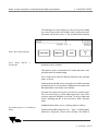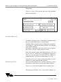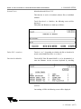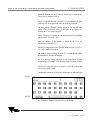
1
MHW -1012E/1018E MULTI-HEAD W EIGHER SERVICE MANUAL
9.2
SOFTWARE
INSTALLATION AND
CONFIGURATION
9. CONSOLE SETUP
The Multi-Head console has two virtual disk drives, namely A and
C. Drive A is an EPROM based drive and is used to load the
startup procedures. Drive C is a solid state flash disk with a
capacity of approximately 2Mb and is used to store the data such
as PLU information.
Software installation and configuration is carried out between the
Multi-Head and a PC via the Squirt software which should be
running on both machines.
Connections
The Multi-Head should be connected to the PC via a 5 pin DIN to
9 or 25 pin male D type data transmission cable (depending on the
connector on the PC).
The 5 pin DIN plug should be connected to the lower of the two
sockets on the front panel of the Multi-Head console. The sockets
are protected by blanking covers which should be replaced once
the setup or data transfer is complete.
The 9 or 25 pin D type plug should be connected to either COM1
or COM2 on the PC. - See PLU Data Transfer
The data transmission cable is available either from Digi Europe or
your local distributor.
To allow input of data paths and filenames on the Multi-Head a PC
keyboard with a 5 pin DIN connector should be connected to the
uppermost of the two sockets on the front panel of the console.
Start Menu
Console software installation and configuration is carried out via the
Start menu which is accessed from the operation menu by holding
down the shift key and pressing 1 9 7, then releasing the shift key.
9 - 7 Issue 1 (9/97)
MHW -1012E/1018E MULTI-HEAD W EIGHER SERVICE MANUAL
Start Menu Option 6 - Transfer
PLU Files
NOTE!
9. CONSOLE SETUP
If the Multi-Head console is to be replaced, or if a secure copy of
PLU data is required, PLU data should be transferred from to a
PC as follows:
1.
Switch on the Multi-Head, if the machine enters the HOST
software (for normal operation), then, using the keypad,
hold down the SHIFT key and press 1 9 7.
On releasing the SHIFT key the Start menu is accessed.
If the message “Host not available” is displayed, the
machine will enter the Start menu immediately.
2.
Select option 6 - Transfer PLU Files from the Start
menu by touching 6 on the keypad.
3.
The PLU Transfer menu will be displayed.
4.
Start the PLU Transfer software on the PC, either by
selecting the relevant drive and directory from the DOS
prompt and typing PLU_RXTX and then pressing
Return, or double-click on the filename PLU_RXTX .EXE
in Windows.
5.
Press the 1 key on the PC’s keyboard such that the
number 1 or 2 is displayed next to the Toggle com port
option. Selection will depend on which COM port is in
use.
a)
The Com Port should be set by default to COM2
b)
In case of any problems establishing which COM port
should be used on the PC (for example if the ports are not
labelled), disconnect the PC’s mouse (assuming it is
connected via a serial port) and attempt connection as
follows:
Connect via one COM port on the PC and set COM1 as
the data transfer port on the PC (See PLU Data
Transfer) and attempt PLU Data Transfer. Should this fail
an error message will be displayed on the PC and the
Multi-Head. In this event, attempt connection via the same
COM port on the PC but set the PC’s data transfer port
to COM2.
Should an error still occur, connect via the other COM
port on the PC and set the PC’s data transfer port to
COM1. In the event that an error occurs again, set the
9 - 8 Issue 1 (9/97)
MHW -1012E/1018E MULTI-HEAD W EIGHER SERVICE MANUAL
9. CONSOLE SETUP
PC’s data transfer port to COM2.
6.
Press 3 to start the “Receive PLU” process on the PC.
The message Receiving the PLU will be displayed on the
PC. The number of transmission retries and the
percentage of data received and saved is also displayed.
NOTE!
7.
Press the 2 key on the Multi-Head keypad, the PLU data
will be transferred to the PC
a)
The message Sending the PLU will be displayed
on the Multi-Head. The number of transmission
retries and the percentage of data received and
saved is also displayed.
b)
If the number of retries increases significantly from
0, a problem with the link may be indicated. In the
event that the transfer fails, an error message will
be displayed to this effect, in which case the
connections should be checked and corrected as
appropriate and the process retried.
c)
The message Done! will be displayed on the
Multi-Head and the PC when the data has been
transferred.
NOTE!
8.
Press the C key on the Multi-Head to return to the Start
menu.
9.
Press the SPACE bar on the PC to return to the Start
menu.
9 - 9 Issue 1 (9/97)
MHW -1012E/1018E MULTI-HEAD W EIGHER SERVICE MANUAL
9. CONSOLE SETUP
Specific file directories must be set up on the Multi-Head prior to
using the Squirt software to download new files:
Start Menu Option 2 - Download
New Files
1.
Switch on the Multi-Head, if the machine enters the HOST
software (for normal operation), then, using the keypad,
hold down the SHIFT key and press 1 9 7.
On releasing the SHIFT key the Start menu is accessed.
If the message “Host not available” is displayed, the
machine will enter the Start menu immediately.
2.
From the Start menu, hold down the SHIFT key and
press 9 9 on the keypad. On releasing the SHIFT key the
C> DOS prompt is accessed.
3.
Check for the directories MHW, LANGUAGE and
DOS5 by using the DIR command on the keyboard and
pressing return.
4.
Should the directories not exist, create them using the
following commands:
MD MHW <return>
MD LANGUAGE <return>
MD DOS5 <return>
5.
The setup software should now be transferred from the PC
to the Multi-Head using the Squirt software.
To avoid compatibility problems, the same version of Squirt should
be used on both the PC and the Multi-Head.
6.
Start the Squirt software on the Multi-Head as follows:
7.
Enter the Start menu, either by turning the Multi-Head off
and on again, or by logging onto its A: drive at the DOS
prompt (See Steps 1 and 2) by typing A: and then pressing
Return followed by typing START and pressing Return.
8.
From the Start menu select option 2 - Download New
Files.
NOTE!
9 - 10 Issue 1 (9/97)
MHW -1012E/1018E MULTI-HEAD W EIGHER SERVICE MANUAL
9. CONSOLE SETUP
9.
Press the 1 key on the keypad or on the keyboard
connected to the Multi-Head to adjust the Toggle Com
Port option such that 1 or 2 is displayed next to the Using
Port field. Selection will depend on which COM port is
in use (See Note Step 4 of PLU Data Transfer).
10.
The receiving mode can be either CACHE or NORMAL.
CACHE mode allows faster transfer of data. If problems
are experienced, switch to normal mode. - To set the
receiving mode, press the 2 key on the keypad such that
NORMAL or CACHE is displayed as desired next to the
Receiving Mode field.
Selection of NORMAL or CACHE receiving mode does not
affect the transmitting machine.
11.
When the PC is running and connected to the Multi-Head,
start the Squirt software on the PC either by selecting the
relevant drive and directory from the DOS prompt and
typing Squirt and then pressing Return or double-click on
the filename SQUIRT.EXE in Windows.
12.
Press 4 on the keyboard connected to the Multi-Head to
select the option Receive File. The message “Waiting for
file on com2” will be displayed.
13.
Select the required com port in the same way as on the
Multi-Head.
14.
At the prompt Enter source path and filename, type the
path and the desired filename at the PC as follows:
NOTE!
a:\<directory>\<filename> then press Return.
(Where a: is the drive on which the Digi software is
located).
For example, to select the file HOST.EXE in the directory
A:\MHW, type a:\mhw\host.exe and press Return.
15.
On pressing Return, the prompt Enter destination path
and filename will be displayed. At the PC, type
9 - 11 Issue 1 (9/97)
MHW -1012E/1018E MULTI-HEAD W EIGHER SERVICE MANUAL
9. CONSOLE SETUP
c:\<directory>\<filename> then press Return as before.
The file will then be transferred from the PC to the MultiHead.
The following messages will be displayed on the PC:
Opening <path/filename>
Using port n
Retrys n
Percent Transmitted nnn%
(where n is a number from 0 to 9)
On the Multi-Head, the following messages will be
displayed during reception of a file:
Bytes to Receive nnnn
Writing to path/filename
Using 64000bytes for Cache Mode (If Cache Mode is
used)
Retrys n
Percent Received nnn%
Percent Saved nnn%
When transfer is complete, the message End of file will be
displayed, followed by the message Done! on both
machines.
NOTE!
a)
If an incorrect source path is input and transfer is
commenced, the message “Error can’t open
<path/filename>” will be displayed. In this event either
press the C key on the keypad or the SPACE bar on the
keyboard connected to the Multi-Head to return to the
options menu.
b)
The destination directory must exist prior to using Squirt,
otherwise the message “Can’t open <path/filename> for
output” will be displayed on the PC. In this event press
the C key on the Multi-Head, ensure that the correct
directory is created and specified and retry the transfer.
c)
Each file must be transferred separately. - Refer to the File
List for the list of files which must be transferred.
9 - 12 Issue 1 (9/97)
MHW -1012E/1018E MULTI-HEAD W EIGHER SERVICE MANUAL
1.
9. CONSOLE SETUP
Once transferred, the software must be configured as
follows PRIOR to starting the HOST software.
Press the 5 key to exit from the Squirt software.
Start Menu Option 3 - Configure
Software
2.
From the Start menu select option 3 - Configure
Software by pressing the 3 key.
3.
At the option 1. 12 2. 18, press 1 or 2 on the keypad to
indicate the number of heads with which the machine is
equipped. On the MHW-1012E press 1 and on the
MHW-1018E press 2.
4.
At the next option press 1 to select Normal operation if
only one type of produce is to be processed during a run
or press 2 to select Product Mix if a mixture of produce
is to be processed.
5.
At the Manual Restart option press Return (the Return
key on the Multi-Head keypad is the right hand arrow) to
specify that a faulty module should not be restarted.
To specify that faulty modules should be restarted after a given
number of machine cycles, enter the desired number via the keypad
and press return. A typical number would be approximately 20 to
30. It should be noted that bad drops could occur on modules
being restarted.
6.
At the Timing Hopper option press 1 if no Timing Hopper
is fitted; the display will then move to the next menu.
7.
Press 2 if the machine is equipped with a Single Timing
Hopper; the display will then move to the next menu.
8.
Press 3 if the machine is equipped with a Diverting Timing
Hopper. - If this option is selected a display will then
appear, prompting for selection of the Diverting Hopper
Type. At this prompt press 1 if a Multiple Diverting
Hopper is fitted or press 2 if a Double Diverting Hopper.
The display will then move to the next menu.
NOTE!
9 - 13 Issue 1 (9/97)
MHW -1012E/1018E MULTI-HEAD W EIGHER SERVICE MANUAL
9. CONSOLE SETUP
9.
At the Detailed Data Logging display press 1 to select N
for No or press 2 to select Y for Yes. When set to Y,
operating data is logged to a CSV type data file named
LOGDATA.TXT for analysis by qualified personnel. The
option would normally be set to N.
10.
The Interface option is used to setup the Bagger Interface
such that either the Multi-Head can control the Bagger or
vice-versa.
Press 1 to select Slave - Pan Ready,Tip if the Bagger is
to be the slave (i.e. controlled by the Multi-Head).
Press 2 to select Master - Tip, weight gone (pulse) if the
bagger is to be the master (i.e. controlling the Multi-Head).
Press 3 to select Cam - Tip, weight gone (level sensing)
This function is a special version of option 2 in which the
Multi-Head does not look for the start of a pulse input but
drops if it is ready AND if the pulse input is on.
Press 4 to select Free Run. This option disables
communication with the bagger.
11.
At the prompt “Are you sure you want to make these
changes?” press 1 for Yes or 2 for No.
On selecting 1, the machine will be configured according
to the parameters input.
12.
When configuration is complete the following prompt
will be displayed:
“Which language would you prefer to be in?”
Press one of the following numbers, depending on
which language is required for machine operation:
1.
2.
ENG (English)
DK
(Danish)
9 - 14 Issue 1 (9/97)
MHW -1012E/1018E MULTI-HEAD W EIGHER SERVICE MANUAL
3.
4.
NTL
SV
9. CONSOLE SETUP
(Dutch)
(Swedish)
The languages available at this prompt depend upon which
language files were transferred to the Multi-Head via the Squirt
software from the PC.
On selection of a language the display will return to the
Start menu.
NOTE!
In order to ensure correct machine operation, the Multi- Head
should then be switched off and back on again. The newly entered
parameters and language will then be loaded.
When configuring the console do not switch off the machine unless
it is displaying a menu. If the machine is switched off whilst writing
configuration files the console software may become corrupted.
NOTE!
WARNING!
9 - 15 Issue 1 (9/97)
MHW -1012E/1018E MULTI-HEAD W EIGHER SERVICE MANUAL
9. CONSOLE SETUP
The following Start menu Options are not necessary when setting
up a console but provide extra facilities when carrying out service
operations and provide access to the operation menu such that
Other Start Menu Options
Start Menu
Production
Option
1
production can be resumed.
This option is used to exit from the Start menu and return to the
operation menu for normal running.
Press 1 followed by return, the display will return to the operation
menu, as shown:
In this mode the machine can be operated as it would be in normal
production but access is possible to additional service menus such
that adjustments can be made to the machine.
From the Start menu select option 4. Installation via the keypad.
The screen will display a menu which appears the same as the
operation menu but which has a the letter i in the top right hand
corner, indicating that this is the Installation Mode operation
menu.
Installation Mode allows access to Debug Mode as follows:
Start Menu Option 4 - Installation
Mode
Hold down the shift key and press 0 0 1. Page 1 on Debug Mode
will then be displayed. Please refer to Section 5 for details of
9 - 16 Issue 1 (9/97)
MHW -1012E/1018E MULTI-HEAD W EIGHER SERVICE MANUAL
9. CONSOLE SETUP
Debug Mode.
Touch exit to leave Debug Mode and return to the Installation
Mode operation menu.
Installation Mode menu
In addition to allowing access to Debug Mode, Installation Mode
has its own menu which can be accessed from the
Installation Mode operation menu by holding down the shift key
and pressing 0 0 7 and then releasing the shift key. The following
screen will be displayed:
This function is equivalent to the Detailed Data Logging option in
the Configure Software option of the Start menu.
With a PC keyboard connect to the Multi-Head press N for No
or press Y for Yes. When set to Y, operating data is logged to a
CSV type data file named LOGDATA.TXT for analysis by
qualified personnel. The option would normally be set to N.
Detailed Log File Y/N
Touch System Errors to display a listing of the number of errors
which have occurred during machine operation:
The error counts should be zero. An error count next to a given
item indicates a fault with the corresponding machine function.
Touch exit to return to the Installation Mode operation menu.
This function is used delete a PLU. Enter the PLU number to be
9 - 17 Issue 1 (9/97)
MHW -1012E/1018E MULTI-HEAD W EIGHER SERVICE MANUAL
System Errors
9. CONSOLE SETUP
deleted and touch Delete PLU.
This function is used to download software files to individual
modules.
Touch Download to Modules, the following screen will be
displayed:
Data paths and filenames are made up as follows:
Delete PLU <number>
Touch A:\ or C:\ depending on whether the file to download is
stored on the Multi-Head drive A: or drive C:
Download to Modules
Touch MAIN if the file named MAIN is to be downloaded, or
enter the filename via the on-screen keyboard by touching
ALPHA.
On touching ALPHA the following screen will be displayed:
9 - 18 Issue 1 (9/97)
MHW -1012E/1018E MULTI-HEAD W EIGHER SERVICE MANUAL
9. CONSOLE SETUP
When the filename has been entered, touch exit to return to the
Download to Modules screen.
Touch .COM if the filename extension is .COM, alternatively enter
a full stop via the keypad and enter the desired extension.
The data path and filename entered appear in the top left hand
corner of the screen and can be cleared prior to acceptance by
pressing the C key on the keypad.
Touch Filename to accept the information entered such that it
appears in the Filename: box.
Enter the number of the module to which the file is to be
downloaded and touch To:
Entering 0 will produce a list of module numbers from 1 to 12 or
1 to 18 to which to download.
The number entered will appear in the To: box and the file will be
downloaded to the relevant module.
An error message will be displayed in case of problems during
downloading, for example, if the filename entered cannot be found.
Touch exit on the Download to Modules screen to return to the
Installation Mode menu.
This function is used to set the zero reading prior to calibration for
NOTE!
NOTE!
the Analogue to Digital Converter on a given module.
9 - 19 Issue 1 (9/97)
MHW -1012E/1018E MULTI-HEAD W EIGHER SERVICE MANUAL
NOTE!
9. CONSOLE SETUP
This operation should be carried with no weight in the hopper and
without the door opening dog touching the hopper.
Enter the required module number and touch setup adc. The
module’s zero reading will then be set.
This operation should be necessary only when installing a new
module board which has not been set up.
setup adc
NOTE!
This function is used to restore a specific PLU backup file such that
it becomes the current PLU data file.
NOTE!
This function is useful where a restore be required but the most
recent backup file is in some way corrupt.
Enter the desired backup number - this may be a number from up
to 5, where 5 is the newest and 1 is the oldest backup file.
Touch Restore PLU number.
Restore PLU number
The current PLU data file will then be replaced with a copy of the
selected backup file.
In the event of an invalid backup number being entered, the
message “cannot restore specified file” will be displayed in the
top left hand corner of the screen.
This function is used copy data files from one data drive or
directory to another.
Touch Copy File. The following screen will be displayed:
Data paths and filenames are made up as follows:
NOTE!
Touch A:\ or C:\ depending on whether the file to be copied is
stored on the Multi-Head drive A: or drive C:
Enter the filename to be copied via the on-screen keyboard by
touching ALPHA.
9 - 20 Issue 1 (9/97)
MHW -1012E/1018E MULTI-HEAD W EIGHER SERVICE MANUAL
9. CONSOLE SETUP
Copy File
On touching ALPHA the following screen will be displayed:
When the filename has been entered, touch exit to return to the
Copy File screen.
Touch .EXE or .TXT if the filename extension is .EXE or .TXT.
Alternatively, enter a full stop via a the keypad and enter the
desired extension.
The data path and filename entered appear in the top left hand
corner of the screen and can be cleared prior to acceptance by
pressing the C key on the keypad.
Touch Copy Filename to accept the information entered such that
it appears in the Copy Filename: box.
Enter the desired destination data path and filename in the same
way as the copy filename was entered and touch To Filename:
such that the information entered appears in the To Filename: box.
9 - 21 Issue 1 (9/97)
MHW -1012E/1018E MULTI-HEAD W EIGHER SERVICE MANUAL
9. CONSOLE SETUP
The file will be copied to the destination data path and filename
entered.
An error message will be displayed in case of problems during
copying, for example, if the filename entered or the destination path
cannot be found.
Touch exit to return to the Installation Mode menu.
NOTE!
Touch exit on the Installation Mode menu. The display will then
return to the Installation Mode operation menu.
To exit from the Installation Mode operation menu hold down the
shift key and press 1 9 7, then release the shift key.
The Start menu will then be displayed.
Select option 1 - Production by pressing 1 followed by return.
The display will return to the operation menu.
Exiting from the Installation
Mode menu and Installation
Mode operation menu
Ensure that the i which indicates Installation Mode is no longer
displayed in the top right hand corner of the screen before
commencing normal operation.
If this option is selected an no options are installed, the message
“No options available” will be displayed, otherwise an options
menu will be displayed.
9 - 22 Issue 1 (9/97)
MHW -1012E/1018E MULTI-HEAD W EIGHER SERVICE MANUAL
9. CONSOLE SETUP
Start Menu Option 5 - Options
The following files should be transferred from the disk supplied:
From the root directory:
EGA.CPI
MODE.COM
From the directory DOS5:
DISPLAY.SYS
From the directory LANGUAGE:
TEXT.SV
CODES.TXT
WORD.SV
TRANSLAT.EXE
LANGUAGE.BAT
WORD.NTL
TEXT.NTL
WORD.DK
TEXT.DK
From the directory MHW:
MHCONFIG.18
HOST.EXE
LARGE.SET
18212.TXT
APPENDIX 1 - List of Files to
Transfer via Squirt
The Multi-Head Interface signals operate according to the
following protocols:
9 - 23 Issue 1 (9/97)
MHW -1012E/1018E MULTI-HEAD W EIGHER SERVICE MANUAL
9. CONSOLE SETUP
If the Multi-Head is the slave, the pulse is 200ms.
If the Multi-Head is the master, the signal duration depends on the
other machine.
- “NO VOLT” relay contacts are used.
On EA1-00025-14 relay boards the signal may be 24VDC if the
input to the other machine is floating.
Minimum 200ms pulse, 24VDC relay coil load - this may be
floating. The other machine supplying 24VDC, or 24VDC may be
supplied by the Multi-Head. - In the latter case, the other machine
must provide “NO VOLT” contacts.
The longest permissible pulse width depends on the relative speeds
of the two machines. In general, a 50:50 mark:space signal would
be acceptable (200ms ON, reset of cycle OFF, up to half cycle
ON, half cycle OFF).
On EA1-00025-14 boards the signal connects to an opto isolator,
not a relay.
If the Multi-Head is the slave, it will drop (if ready) on the rising
edge of the input (tip) signal. The signal is not stored, meaning that
if the Multi-Head is not ready the signal must be repeated.
The other machine is expected to signal at the rate at which it is to
operate (for example 60 per minute) but only to pack the product
if the Multi-Head replies to its signal (weight gone). The MultiHead drops at the moment that the tip signal is received and the
weight gone signal is sent.
APPENDIX 2 - Interface Signals
If the Multi-Head is the master, it will assert its output signal (pan
ready) until it receives a signal from the other machine (tip). It will
then remove its signal and drop.
Signals from the Multi-Head
9 - 24 Issue 1 (9/97)
MHW -1012E/1018E MULTI-HEAD W EIGHER SERVICE MANUAL
9. CONSOLE SETUP
NOTE!
Signals to the Multi-Head
NOTE!
Timing
9 - 25 Issue 1 (9/97)