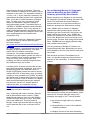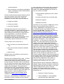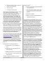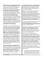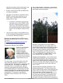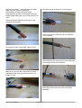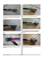
1
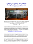
SURREY RADIO CONTACT CLUB 80th Anniversary Year - Founded in 1935 OCTOBER 2015 – No: 878 CLUB NET CLUB NET 1.905 MHz Sunday 9:30am 145.35 MHz +/- 25kHz Friday 8:00 pm CLUB Internet WEB Site: http://www.g3src.org.uk Hon. Sec. John Kennedy G3MCX 22 Croham Park Avenue SOUTH CROYDON Surrey CR2 7HH 020-8688 3322 E-Mail: [email protected] MONTHLY MEETINGS 1ST AND 3RD MONDAYS 7.30 FOR 7.45pm Meetings at Trinity School, Shirley Park, Croydon CR9 7AT *************************************************** 1st MEETING: Monday 5 October .Autumn Surplus Equipment Sale. Auctioneer: Gareth G4XAT 2nd MEETING: Monday 19 October. Fix-it, Move-it-On and Informal Chat. led by John G8MNY. SRCC Committee 2014/15 Chairman & Club Meetings Vice-Chairman and Web Master Secretary & Communications Treasurer & Membership Records Contest Co-ordinator, Newsletter Editor Chief Fund-raiser, Liaison, Recycling, Equipment Committee Member Co-opted Committee Member Dear Members & Friends, Hello and welcome to the October 2015 issue of the Newsletter, edited by John G8IYS. It is pleasant to be writing the Newsletter in the comfort ?? of home, surrounded by decorating materials, rather than travelling to/from the hotspots of France and the UK. The downside is that I have picked up a rotten cold and am struggling to see the screen of my computer monitor. Those who recall that the previous issue was keyed whilst in Genoble, Rhone-Alpes might be entertained with a couple of road and air stories. I flew out seamlessly from Gatwick to Lyon and met up there with my sister-in-law's family who had flown in from Birmingham. Together, we found the pre-booked shuttle bus for the 1 hour journey to Grenoble. Unfortunately, we learned Issue 1 for distribution G4FDN G4FYF G3MCX G4FFY G8IYS G4DDY M0LEP G3WRR Pat McGuinness Steve Jones John Kennedy Ray Howells John Simkins Maurice Fagg Rick Hewett Quin Collier 020 8643 0491 020 8405 5584 020 8688 3322 01732 357474 020 8657 0454 020 8669 1480 01689 851472 020 8653 6948 that the air-con was defective and the temperature within was 36 C. We were given the option of travelling by the next bus, scheduled to depart 1 hour later, but without guaranteed seats. We took the first bus - only to enjoy a breakdown on the Autoroute about 10 minutes later, noting engine coolant spreading in ever-widening circles on the carriageway. After about half an hour, a mechanic arrived and quickly announced that the bus had suffered a mortal wound. After a further half hour... you have guessed it...the next scheduled bus picked us all up, together with luggage and delivered us safely at the far end. We concluded that a better choice might have been to have stayed in the air-conditioned atmosphere of the Lyon Airport bar! While the passengers were taking refuge on the hard shoulder, in the shade offered by the bus, we were all entertained by the breakdown of a car in the fast lane of a two-lane motorway. Our bus Page 1 of 12 occupied half of the first lane! Warning triangles were deployed and much arm-waving took place in an attempt to avoid rear-end collisions. Miraculously, one car managed to get between the stranded vehicle and the central armco – donating its wing-mirrors to charity on the way through. Travelling is such fun. LAST MONTH'S MEETINGS THIS MONTH'S MEETINGS On this occasion it was necessary to hold our informal Meeting on the first Monday of the month. Our Chairman reminded the fourteen Members present that Bryan G6ODE's funeral would be on Thursday. First Meeting: Monday 5 October. Autumn Surplus Equipment Sale. Auctioneer: Gareth G4XAT Just a few Rules: It is very helpful for sellers to be in the meeting room by 7:30pm and to bring no boxes of “rubbish” please. All members and visitors whom they have brought along must sign the attendance book and all must be conversant with the rules. First Meeting: Monday 7 September. Fix-it, Move-it-On and Informal Chat - led by John G8MNY. Report by Hon Sec John G3MCX. Various activities included John, G8MNY modifying his Trio TS700G by adding a CTCSS board. John had also brought in a QSL Card from Doug, GM6ZFI for a contact on 7.091 MHz. This was made on Friday 4th. September 2015. Doug used to live in Waddon until 13 years ago as G6ZFI. Note that the club accepts no responsibility for goods sold at this private sale, and the purchasers buy on the understanding that they are capable of determining the usability, fitness for purpose and SAFETY of goods obtained. The following also apply: 1. Only SRCC members are permitted to sell. 2. All items not donated for the benefit of the Club must be marked with the name or call-sign of the vendor, a brief description and details of any reserve price. 3. Bids shall start at 50p and increment in steps of 50p up to £10 and £1 steps thereafter – unless determined otherwise by the auctioneer. 4. Visitors are welcome but must be introduced by a member who is responsible for informing them of the rules. 5. All members and VISITORS must sign the attendance book. 6. Sellers will not be paid until all buyers have settled up. 7.The club levies 15% on all transactions. Please try and arrive early to allow start by 7.45pm. 8. Please do not obstruct the doorway. This will facilitate escape in case of fire. 9. The school premises are NO-SMOKING Second MEETING: Monday 19 October. Fix-it, Move-it-On and Informal Chat - led by John G8MNY. Issue 1 for distribution Gareth, G4XAT came with a very interesting looking antenna. It was a Planar Disk Aerial. Gareth said Google it! It is worth a look. Two disks are mounted with their rims very close together. They could be round or square. Gareth used two round ones. The lowest frequency is Page 2 of 12 determined by the size of the disks. The coax outer conductor is attached to one and the centre conductor to the other. The separation should be 1.5 mm (1/16 “). As the frequency increases, the gap between the disks becomes two exponential slots - much like a Vivaldi Antenna or a Ridged Horn. To make your own - buy two 18" pizza dishes (not aluminium, difficult to solder) or frying-pan splash guards. This should deliver a 144 MHz to 1296MHz all band vertical including the spectrum between. This is very popular for UWB (Ultra Wide Bandwith) applications such as scanners. [Gareth sent me a couple of URLs and some supplementary text to describe the construction. Ed] ‘In searching the www for a wide band ‘scanner’ aerial to use with my various SDR dongles I found this website: http://www.wa5vjb.com/references/PlanarDiskAnt ennas.pdf As I was browsing, I remembered that Jayne was shopping at IKEA at that moment, so a quick phone call led to another convenient coincidence. We already owned two of their stainless frying pan spatter guards, the result of two ex-student house contents returning home. They are too big for our frying pans, but inevitably, as there is nothing wrong with them, they had been kept, just in case….. Second Meeting Monday 21 September. Antenna Modelling by Quin G3WRR. Summary provided by Quin himself. Before introducing our Speaker for this evening, the Chairman opened the meeting and said a few words. Pat welcomed the eleven members present and went on to say that unusually we had three apologies for absence this evening. John, G8MNY who we knew is in 'Mayday' hospital has made good progress. He will be allowed to go home tomorrow if the Doctors are happy with his test results. John, G3ENG our former Vice Chairman is now the full time Carer for his wife, Benita who is still recovering from a severe stroke. Pat saw John during the weekend. Dave, 2E0EBK has been digging ditches today and is rather tired and dirty. Our next meeting on Monday 5th October is a Surplus Equipment Sale. Bring what you can to sell or donate to the Club. Buy items to help raise Club funds. With this final comment, Pat handed over to Quin, our Speaker tonight who has just been coopted on to the Committee. 10 members were present. A suitable piece of timber was selected and the two guards secured by entrapment, thus saving spoiling the guards if the idea didn’t work. A length of RG58 was pressed into service and so was the MFJ 259. It does what it says, providing a match of sorts upwards from 70 MHz, including the 70cms band as tested with Pats full coverage MFJ259. I’d guess it’s just a variation on a dipole made from broad tape-measure type material, but carried to extremes. If anyone wants to replicate the idea, you need two of these http://www.ikea.com/gb/en/catalog/products/1011 2530/ for £3 each. With the addition of a piece of wood, you could be in business.’ Now, continuing with John's summary: Maurice had an M8 transistor tester (version, 12864) which he had made up from a kit. Nick Phillips, 2E0BPU brought along a very nice, well made heavy twin paddle key. This was made by Bengali, it was a pity that Nick did not bring the correct lead with him or we could have tried it out. Quin opened by outlining the presentation, which would be HF-focused, although many of the principles also apply to VHF. It would include: why members might wish to try antenna modelling a demonstration of some of the available modelling software a display of some of the more interesting Issue 1 for distribution Page 3 of 12 antenna patterns if time permitted, an “audience participation game” to design an antenna and examine its radiation pattern. own knowledge of the program) did not permit a full training session. The opening page allows details of the two end points to be entered, in one of a number of formats: a preset default (typically the user’s home location) He then reassured those present that they would still make contacts if they didn’t model their antennas! The key things to do, within the limitations of the site, were to get the antenna: a location selected from an internal atlas latitude & longitude as high as possible Maidenhead locator. as long as possible centre fed if possible. This approach works well, but if one has a particular application in mind modelling could be very helpful. Quin exemplified this by talking about optimising an antenna for skeds with his purely hypothetical - chum Boris in Bavaria (specifically Munich as the angles are convenient). However, he had in practice used the approach in an attempt to (none too successfully) optimise antennas for HF NFD. The key steps in such cases are to: work out where you want the antenna to fire work out the chosen antenna’s radiation pattern match the two. Software tools are available on the internet to facilitate the first two. Direction can be obtained from a map – a Great Circle map is best, but for relatively short distances the familiar Mercator projection should be good enough. Elevation must be considered too: the optimum elevation angle depends on the distance between the two terminal points and the height of the ionosphere. The angle can be determined from fairly straightforward geometry if the height of the ionosphere is known - but this can vary between 90km (E layer) and 600km (F2 layer). However, help is available from the W6ELProp program: this is freeware and is available from http://www.qsl.net/w6elprop. Information is also required on date (the current date is used as default unless another is chosen), solar flux at a wavelength of 10.7cm (or alternatively the more familiar sunspot number) and K index. The latter two, which are freely available on the internet (eg. at http://dx.qsl.net/propagation/propagation.html) both relate to emissions from the sun. The former consists of electromagnetic radiation (photons), and the latter is particulate emission (the solar wind). The photons ionise the atoms in the upper atmosphere – thus creating the ionosphere – so the higher the solar flux, the better. The solar wind consists of positive and negative ions which interact with the earth’s ionosphere and can (simplistically) be thought of as partially “shorting out” the ionosphere. Thus a high level of solar wind is bad from a propagation point of view. The solar wind “remembers” the solar magnetic field and this remembered field interacts with the earth’s magnetic field (much as two permanent magnets will attract or repel each other). So the stronger the solar wind is, the more the earth’s magnetic field varies (measured as a high K index). Hence we get an indication of the damage done to the ionosphere by the solar wind from the magnitude of the K index. In summary a high solar flux and low K index indicate good conditions and vice versa. Having input the above information, W6ELProp displays a page showing information of distances and bearings (long and short paths). In the case of Boris in Bavaria short path is all that is needed. Two further pages follow, showing information, at half hour intervals and for chosen frequencies, on: Quin gave a demonstration of W6ELProp – just a brief taster of what it could do as time (and his Issue 1 for distribution Page 4 of 12 Maximum Usable Frequency Path availability (i.e. the probability that there will be a viable path) Estimated signal strength or signal to noise ratio for that path Elevation angle Ionospheric layer(s) used. In the example demonstrated (Croydon – Munich path, solar flux of 100, K index of 3) two alternative elevation angles were possible – 31o via the F layer and 14o via the E layer. The preferred one to use can be deduced from the other information available. For example if the band to be used has already been decided, the path availability and signal strength can be used to establish the best time (in the example shown if 40m had been chosen, any time between 0600 & 2100 would offer good path availability, with best signal strength between 1830 & 2100). Conversely if a sked time of 0400 had been chosen, it could be seen that 40m was not viable due to low availability, but excellent availability was possible on 80m at good signal strength. Before leaving W6ELProp, Quin demonstrated a much longer path (Tasmania, VK7). In that case, both long and short paths were possible (but with better availability on short path), and in all cases involving multi (up to 9) ionospheric hops, at elevation angles generally less than 5o. Having now established the desired direction and elevation, Quin explained that help was again at hand in the form of EZNEC, available from http://www.eznec.com . This is not free, but starting at $99 it does represent good value. Although it will not tell you what type of antenna to use, it will allow a chosen type of antenna to be optimised in terms of dimensions, orientation and height for a particular job (eg. the skeds with Boris…). It allows the user to define an antenna: by entering the x, y & z coordinates of wires multiple wires are supported (eg. in the case of a beam) feeders, traps, stubs etc. can be included with a wide range of ground conditions and element losses. Available outputs from EZNEC for such an Issue 1 for distribution antenna include: pictorial representation of the antenna and current distribution Three dimensional radiation pattern and two dimensional azimuth and elevation patterns impedance and SWR Display of overlaid of antenna patterns for comparison purposes. Quin now demonstrated EZNEC again, as with W6ELProp, offering just a taster of its wide range of features. He started with a horizontal 40m dipole in free space, which has a doughnut shaped radiation pattern - as we all hopefully remember from our RAE or equivalent! Although in this case a pre-prepared antenna definition was used (files for such antennas being chosen via the usual Windows file selection window), any antenna can be defined and input using the (tab selectable) “Wires” page. This allows the x, y & z coordinates of the end points for each wire to be input, together with wire diameter and number of segments to be used in the modelling (the model breaks the antenna down into a number of segments each of which carries the same current): generally the more segment used the better – albeit sometimes at the price of lengthy run time. The position of the feed point can be input using the “Sources” page. Quin then showed a picture of the antenna and its current distribution by selecting the “View Ant” page. This is perhaps unnecessary in this simple case, but provides a useful sanity check which has got him out of all kinds of trouble in the case of more complex antennas! He next checked the antenna’s SWR by selecting the “SWR” page. This produces a graph of SWR against frequency (the limits of frequency scan and step size are user settable), together with impedance (resistive and reactive components) at any chosen frequency. He noted that at the resonant frequency, corresponding to minimum SWR, the reactive component is zero. In the case demonstrated the resonance was outside the band so he showed how to adjust the element length using the “Wires” page. Once the length had been adjusted to offer a good SWR, the radiation pattern was investigated by selecting the “FF plot” page. This initially shows a 3 Page 5 of 12 dimensional plot, but for this antenna it is not too helpful. Accordingly the “Show 2D plot” box was selected. This allows two dimensional views (either azimuth or elevation) to be displayed. In azimuth view, the azimuth plot at varying elevation angles can be shown, and the gain at various azimuth angles displayed. Likewise, in elevation view, the elevation plot at varying azimuth angles can be shown, and the gain at various elevation angles displayed. The same information can be displayed in tabular form (and is useful in this form for spreadsheeting purposes) but in most cases from a human comprehension point of view the two dimensional views give the clearest idea of what the antenna is doing. Files depicting the azimuth & elevation patterns can be saved for subsequent examination if required. In the case of the 40m dipole in free space, the azimuth pattern showed a figure of eight shape, and the elevation pattern was circular along the line of the antenna – as is to be expected from 2 dimensional representation of a doughnut shape. Quin then moved on to demonstrate the same 40m dipole over a perfect ground (the choice of ground type being made on the “Ground type” page). Unlike the free space case, where height has no meaning, over any kind of ground a height must be shown. This is achieved by setting the z coordinates appropriately on the “Wires” page. It is possible to change the overall height in a single action rather than having to modify each wire individually: similar capabilities allow individual wires to be changed by any angle in the x, y or z planes. Inspection of the azimuth pattern still showed a generally figure of eight azimuth pattern – but now the elevation pattern showed a strong lobe at an elevation angle of 32o, and near zero gain at zero and 90 o. Also the gain at 32o, at 7.9dBi, is much higher than that of the free space case at 2.0 dBi. This is due to the concentration of power in some directions rather than unidirectionally – rather like an optical searchlight. Quin then demonstrated the 40m dipole over a real ground, using one of the optional ground types offered by EZNEC. In this case the strongly lobate pattern was remained, but at slightly lower gain (1.6 dB down on the prefect earth case) and at a lower elevation angle of 28 o. He then showed a slide comparing the performance of the 40m dipole in free space, over perfect ground and over a ground type typical of Croydon. elevation pattern was due to the appearance of an “image antenna” in the ground. Different path lengths between signals generated by the real and image antennas at a distance meant that they alternatively added and subtracted as the elevation angle changed. Quin then introduced another useful feature of EZNEC, in the form of a “program within a program” named Traceview. This enables previously saved azimuth and elevation patterns to be displayed on the same axes for comparison purposes. He demonstrated Traceview by overlaying patterns for our 40m dipole over real ground at 10ft height increments between 30ft & 100ft. Knowing that the optimum elevation angle for Boris was 31o, it could be seen that the overlaid elevation pattern at 70ft was the best fit. If necessary, smaller height increments could be modelled and displayed to obtain a more accurate assessment of the optimum height. (Of course, one has to ask how many of us could get a dipole up at more than 60ft! ) He noted that establishing the optimum antenna orientation is more straightforward than its height. In simple cases like this, it is probably easiest to display the azimuth pattern on a transparency and rotate this over a map until the main lobe and target direction coincide, then orient the antenna appropriately. Before (mercifully) finishing his EZNEC demonstration he showed the effect on azimuth pattern obtained by using the same antenna (a 274ft doublet 33ft up, as frequently used in NFD) on the six non-WARC bands between 160m & 10m. Starting at 160m, the pattern is broadside and fairly wide. As the frequency rises, the main lobe gets narrower then splits into multiple lobes that progressively change from broadside towards end-fire. He also demonstrated the use of EZNEC to model a multi-element antenna using 16 wires in the form of a cubical quad, and displayed the directional pattern that it generates. Owing to time constraints, the suggested “audience participation game” did not take place. However during the Q & A session, the following points came up: He explained that the very marked change of Issue 1 for distribution Page 6 of 12 other antenna modelling programs existed, but Quin had had no experience of these. It was believed that these use the same “core engine” (NEC2) or its successors, with the alternative programs offering alternative user interfaces to the underlying core engine likewise, Quin had not read the ARRL book on antenna modelling and again, he had had no experience using EZNEC to model loops (believed to be a weak area) or antennas which included loading coils or traps Why ¾ wavelength? –because a ¼ wavelength is physically too short to physically span the one wavelength vertical separation. in answer to a question on how long it had taken him to “learn” EZNEC, Quin said he On had just picked it up as he want along, and found it fairly intuitive – but noted that people who have already learnt to use a program usually do say that! Quin would be happy to bring EZNEC along to Fix-it meetings to demonstrate it further, or run members’ antennas through it. Members can download Quin's PPP from the Meeting Downloads page of the SRCC website. The link is: http://www.g3src.org.uk/downloads.html and scroll to the bottom of the list. Chairman's Blog by Pat G4FDN Antenna experiments: I know several of our members are into antenna modelling, (G4XAT, G8MNY and G3WRR) but I’m more of a ‘suck it and see’ person, and I then revert to theory if expectations are not met in practice. For many years, I have been using a 2m Slim Jim for 2m FM, and also on 70cm too, but I recently decided I would make a comparison with a 70cm Slim Jim. For testing, I mounted two 70cm Slim Jims on a wooden pole, stacked vertically a wavelength apart and fed in phase. This entailed making a ¾ wavelength of 75 ohm coax for each Slim Jim to transform the 50 ohm nominal impedance to 100 ohms with both then connected to a T connector, such that the impedance on the third port of the T was 50 ohms. Issue 1 for distribution Based on a suggestion from John G8MNY, I mounted the lower Slim Jim upside down. The picture above shows them on the pole at ground level. I did a test with them mounted about 25 feet above ground and they performed about one S point better than the 2m Slim Jim was on 70cm. The SWR was low: varying from 1.2 to 1.4:1 from 430MHz to 440MHz. Maybe I’ll ask Quin G3WRR if he can model it for me. Crimp Coax Connectors: I have written about crimp connectors before, but as a pre-cursor to my antenna experiments above I replaced a length of coax and connectors feeding the 2m Slim Jim. For most of the length, the coax is solid core dual braided lower loss version.5db less loss on 70cm. I documented the assembly procedure in the following photographs. This was mainly using RG213, with the last metre or two feeding the rig and the Slim Jim being the more flexible RG8X. So, for the latter, I chose crimp-type N connectors. On these, the braid is crimped and the centre pin is soldered. It is possible to get connectors that have crimped centre pins too, but these are harder to find and more expensive. Page 7 of 12 Why do I like them? – because there are fewer parts, they are quicker to assemble, mechanically stronger compared to the compression type and on comparative tests on similar length leads gave up to 0.5db less loss on 70cm. Strip 4mm-5mm off the inner core insulation. I documented the assembly procedure in the following photographs. Put the connector centre pin over the exposed core conductor. First strip the outer sleeve back 14mm-15mm Then solder the pin and trim the outer braid back to the length of the core insulation. Make sure you have the crimp sleeve in place – especially if this is the second connector on a length of coax. Get ready to offer the outer shell to the cable assembly.... Issue 1 for distribution Page 8 of 12 Push the cable assembly with centre pin into the N connector housing ensuring the braid stays on the outside. Then push the crimp sleeve over the outer coax braid. This is when you use the crimp tool. For RG8X it uses the second largest hex shaped hole in the crimp die. Issue 1 for distribution This is how it looks after being crimped. I usually add some heat shrink sleeving to give some added protection to the crimp sleeve. In the example above I used some transparent sleeving. After applying heat, the sleeving shrinks to a tight fit around the crimp sleeve. Page 9 of 12 not just an activity to acquire yet more kit and components, but as one where you contribute to an essential fundraising activity for the club. I surely don’t need to point out that the SRCC membership sub is not on its own sufficient to cover club expenses. So, please do as many of the following as possible: If the connector is destined for outdoor use I usually add a second sleeve that goes over the collar of the N connector with some silicon grease in between the two layers of heat shrink tubing. 50 ohm F Connectors: But, I hear you say, F connectors are 75 ohm ! Well, they are most often used on TV and satellite 75 ohm coax assemblies, but the actual impedance is dependent on the coax core inner diameter in relation to the outer, so if you use 50 ohm coax that fits the outer diameter of the F connector you do by definition have a 50 ohm F connector. Here is one I made up using RG8X. The inner of the RG8X is soldered to make it solid and avoid fraying. Club 4m FM net: Though there hasn’t been any further interest expressed other than by Dave 2E0EBK and myself, we will kick off a trial net between ourselves in the next few weeks and see if it catches on. Date, time and frequency will be advised via email and the next newsletter. Surplus Equipment Sale: This is the time of the year when you need to position your participation in this event, with spouse, partners and family, as Issue 1 for distribution • Attend the surplus equipment sale • Bring along items to sell or for donation to the club • Buy some of the items up for sale The more of the above you do the more you are helping the club, and in so doing you may well get a great bargain. Sign-off: I’m hoping to see as many of you as possible next Monday, especially those members we haven’t seen for a while. Bryan Aylward G6ODE SK by Hon Sec John G3MCX Bryan's funeral was at the Croydon Crematorium on Thursday 10th. September 2015. The service was very tastefully led by the Rev. Peter Wyatt, Minister in charge of St. Francis Church, Monks Hill, Selsdon. There was a good turnout and the atmosphere was very calm and peaceful. During the service the Minister read out a tribute to Bryan by one of his lifelong friends, Ru. As a schoolboy Bryan always enjoyed electrical and mechanical things rather than arty subjects; he probably acquired this leaning from his father. In his final year at school, he was able to spend some time at a local technical college doing electrical engineering. Because of rules and regulations, he had to return to school and carry on with subjects which he found incredibly boring and time wasting. It was probably the start of his lifelong dislike of petty bureaucracy, which was further reinforced by his National Service. He couldn't understand why a person skilled in electronics and radio should become a clerk. After working for several companies, he set up a business repairing valves for RF heating generators. This kept him occupied until he retired. During this time he owned an old style Bentley and a half share in a Chipmunk aeroplane. This was sometimes used to take valves to and from customers all over England. Bryan would sit in the rear seat with the valves balanced on his knees as due to slightly high Page 10 of 12 blood pressure he was unable to get a pilot's licence. Apart from re-building valves, he took an interest in amateur radio and later amateur TV but became disillusioned when many amateurs chose to buy ready made equipment. He always preferred to design and build his own. He had a room, a garage and shed full of equipment plus a large antenna in the garden. Later in life, with deteriorating eyesight and miniaturisation, he found it impossible to solder tiny components. He designed an optical system to keep going a bit longer. He would also buy a cheap hearing aid, strip it down and improve it. He survived cancer and MRSA some years ago but recently spent five weeks in hospital. He came home and appeared to be recovering well, but was taken back in and sadly never came home again. Main Band (Full TX/RX) 410MHz – 470MHz. (Units have been modified to transmit over the FULL frequency range by Kenwood supplied procedure). R.F. Power Output 35 watts (High Power) 10 watts (Medium) 5 watts (Low) Sub-Band 1 FM RX only 136 MHz. – 174 MHz. FM. Sub-Band 2 FM RX only 800 MHz. – 999.975 MHz. FM. For more information on these transceivers check out the following two web-sites:- Bryan had two main claims to fame, Gladys Aylward as immortalised in the film 'The Inn of Sixth Happiness ' was one of his aunts. He also brought the entire British Leyland production of the Mini Metro to a halt because they hadn't paid his bill. He refused to give them any more valves until they did. With thanks to the Rev. Peter Wyatt for sending me a copy of this tribute and to Ru for allowing me to use it. Everyone was invited back to the house afterwards and enjoyed the hospitality and conversation. The SRCC was represented by Bert G0IZB, Maurice G4DDY and Johns G8MNY and G3MCX. I later found out on e-mail exchanges that the Rev. Peter Wyatt had a few years ago worked in the engineering world for Electrosonic on product development. Many years ago, he was licensed as G6FXJ although he was never very active. This explains why he didn't query my e-mail address in the car park, as most people do. Peter may come to one of our Club Meetings if he has the time. STILL ON OFFER BY G3NGK Readers will recall that some months ago, David posted the following offer. Well, the items are still available. TWO Kenwood TM451E 70cm FM Mobile Transceivers, either singly or both together. Brief specification is as follows:Issue 1 for distribution http://www.rigpix.com/kenwood/tm451e.htm http://www.radiomanual.info/schemi/TM251_user .pdf Both units are offered with a car mounting bracket and a User Instruction Manual. I also have ONE original copy of the full TM451E Service Manual. I have been using these transceivers for quite a few years and they have given excellent service and are still fully functional. Anyone wishing to inspect them or requiring more information is welcome to call me on (020) 8462 2178 (located in Hayes, Bromley.) I am not expecting payment for these the transceivers, but am offering them on the condition that whoever takes them will, after confirming that they fully meet his/her expectations, make a sensible monetary donation by cheque to the Alzheimer’s Society, either sending it directly to them or to me to forward on. 73 – Dave G3NGK. Email: [email protected] Page 11 of 12 Stolle Light Duty Rotator for sale I have to confess to losing this ad for a couple of months. While the NESCG Team was operating from the top field of Warren Barn farm in VHFNFD, we were approached by a local SWL who had come up the hill from Westerham to say hello. He wondered whether he might also use our good offices to find a new home for his Stolle Antenna Rotator. I would say that £30 would be good starting point for haggling. Where did I refind the ad? It was written on the back of the operators' rota for the 70cm station! Contact Richard Howard on 01959 564030 or [email protected] RSGB Convention Sat/Sun 10/11 October Do not miss this event, which takes place at Kents Hill, Training & conference Centre, Timbold Drive, Kents Hill Park, Milton Keynes, MK7 6BZ. Details on RSGB Website. CATS Bazaar Sun 15 November. 10.00 am An early reminder that CATS Bazaar will be held at Coulsdon Community Centre, Chipstead Valley Road, Coulsdon, CR5 3BE. SRCC will be one of the many stallholders there. Sign Off. I am sorry, but this is another month without details of Other Clubs' Meetings. The Newsletter is late enough already, through my cold and I simply cannot spend more time on it. Business as Usual next month. 73. John. G8IYS Editor. Issue 1 for distribution Page 12 of 12