1
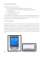
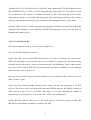
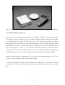
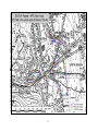
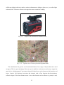
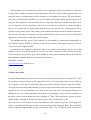
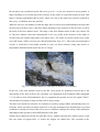
PROVINCIA AUTONOMA DI TRENTO
Servizio di Sistemazione Montana
PROVINCIA AUTONOMA DI BOLZANO – ALTO ADIGE
Azienda Speciale per la Regolazione dei Corsi d’Acqua
e la Difesa del Suolo
AUTONOME PROVINZ BOZEN – SÜDTIROL
Sonderbetrieb für Bodenschutz, Wildbach und
Lawinenverbauung
CONSIGLIO NAZIONALE DELLE RICERCHE
Istituto di Ricerca per la Protezione Idrogeologica
Sezione di Padova
Interreg III Project Alpine Space
Disaster Information System of ALPine Regions (DIS-ALP)
Work Package 7 - Innovative Tools for Information Collection
Progress Report 1
(GPS, laser distantiometer, grain size analysis)
Silvio Grisotto
Bruno Mazzorana
Lorenzo Marchi
Marco Cavalli
Andrea Zannoni †
(Autonomous Province of Trento)
(Autonomous Province of Bolzano)
(CNR IRPI)
(CNR IRPI)
(CNR IRPI)
2005
1. Introduction
The aim of Work Package 7 (Innovative Tools for Information Collection) is to develop and test
methodologies and techniques for making the field documentation process more efficient, thus
increasing the possible number of recorded events as well as the quality of recording.
This preliminary report summarises some experiences regarding the use of up-to-date technologies
suitable for the post-event topographic surveys of mountain disasters (GPS, laser distance meter).
Improved archiving methods for traditional survey techniques (particle size analysis of gravel-bed
channels and debris flow deposits) are also considered.
The report presents also the results of a questionnaire distributed to Italian offices involved in the
post-event survey of mountainous disasters.
2. Questionnaire
A questionnaire about the current use of some up-to-date technologies and procedures in post-event
surveys (Table 2.1) was sent to some offices and authorities involved in watershed management and
torrent control works in Northern Italy.
Table 2.1 – Questionnaire on technologies in post-event surveys in the Italian Alps.
Technology / type of survey
Use
GPS (type of instrument)
__ methodical
________________________________________ __ occasional
________________________________________ __ only for the most important events
laser distance meter
aerial laser-scan
measurement of particle size of channel-bed
material and deposits (grid-by-number or other
techniques)
other (specify)
________________________________________
________________________________________
__ methodical
__ occasional
__ only for the most important events
__ methodical
__ occasional
__ only for the most important events
__ methodical
__ occasional
__ only for the most important events
__ methodical
__ occasional
__ only for the most important events
We received only a few answers, so that a statistical analysis of the results is not possible. It seems
that GPS surveys and aerial laser scanner are receiving some attention, although with remarkable
difference between different institutions involved.
2
In order to extend the collection of information about the use of innovative tools in the survey of
mountain disasters, we have asked the collaboration of project partners. Dr. A. Loipersberger
(Bavaria) provided some information about potential and possible problems regarding the use of
GPS and aerial laser scan.
3. Preliminary experiences in the use of GPS in post-event surveys
Experiences regarding the use of two GPS receivers (Trimble Pathfinder Pocket Receiver and GPS
GeoExplorer CE GeoXT) are reported hereafter. The Trimble Pathfinder Pocket Receiver was used
in the survey of some debris flows in the Province of Trento; the use of the Trimble GeoExplorer
CE GeoXT regarded the survey of gullies and shallow landslides in a hilly area near Padova.
3.1 GPS Trimble Pathfinder Pocket Receiver
The instrumentation consists of the following tools:
-
GPS Trimble Pathfinder Pocket Receiver: it is a very small and light portable receiver,
proper to GIS applications, with a declared precision of 10 meters without differential
correction and 2-3 meters with differential correction. The receiver is positioned on the head
of the user in a special hat.
-
CompaQ IPAQ palm PC with the software ESRI ArcPAD, linked to the GPS receiver by
means of a special serial-USB cable. This tool permits to visualize raster maps or aerial
orthophotos of the survey zone (in different compression formats). This allows to follow, in
real time, the movement of the operator in the field and to make a first check of collected
data.
-
The software Trimble GPS Correct completes the whole system, for the receiver setting and
the data collecting in compatible formats with the differential correction software (Trimble
Pathfinder Office).
The first tests of these tools are carried out from June to August 2003 during the field survey of
some debris flows triggered by intense rainstorm in the Province of Trento. In particular, we have
carried out some tests to permit us a first evaluation of fundamental technical and economical
aspects:
-
Precision of the data collection, with and without differential correction;
3
-
Facility of GPS signal receiving and problems due to satellite cover and geometric position
in the sky;
-
Comparison between the features surveyed with the GPS receiver and those manually
designed on the map;
-
Survey velocity and productivity of the tools;
-
Facility and convenience of transport in field: tools size, weight and links;
-
Precision/price relationship with respect to other more expensive systems.
Hereafter we summarise main advantages and drawbacks arising from the experience of early tests.
Advantages
a. Possibility to evaluate, in real time, the accuracy of the collected data;
b. Easy orientation of the user in the field, particularly in unknown zones and away from urban
areas
c. Easy recovery of positions already collected, in case of surveys in the same area;
d. Fast and immediate data collection: the stationing time can be very short;
e. Possibility to use the palm PC to annotate field notes and information or to compile data
sheets and databases;
f. Easy download and post-elaboration of the data;
g. Possibility to compile directly in field an attribute dbase linked to all the features collected;
it becomes easy to use with a GIS system after having downloaded the data in office;
h. Good precision-price relationship with respect to other more accurate, but more expensive,
receivers (i.e. topographic GPS);
Drawbacks
a. Discomfort of the link cables between palm PC and receivers; this can be a problem when
you develop a survey in very dense woods and in very steep and slippery slope (landslide
body, rocks, streams with abundant water discharge, etc.); in this areas, often, the user must
walk also using the hands;
b. Palm PC connection port is very delicate and easily breakable if you don’t use with care: the
cable tends alone often to disconnect from the palm PC;
c. All the instrumentation is very sensible to water; it becomes impossible to carry on surveys
during rainy days; unless proper devices are used to protect the tools (e.g. rugged case);
d. It’s very difficult to receive the GPS signal in very impervious areas (i.e. very narrow and
deep valleys), in dense urban areas with very high buildings, dense woods. In these cases
you can fail to receive any GPS signal because the satellites are too low to the horizon, or
4
you can receive a GPS signal affected by errors due to multipath and high values of the
PDOP (Position Dilution of Precision).
3.2 GPS Trimble GeoExplorer CE GeoXT
The activities outlined herein were carried out as part of a project run by the Regional Park of
the Euganean Hills: http://www.parcocollieuganei.it/.
The Regional Park of the Euganean Hills equipped its surveyors with a palmtop, which
included a built-in GPS receiver, so that a survey could be made of the river system, eroding areas,
and surface landslides within the basin of the Euganean Hills. The GeoExplorer CE (GeoXT
model), which is produced by Trimble, was used for the survey (Fig. 3.2.1).
Fig. 3.2.1 – Trimble GeoExplorer Ce GeoXT.
This Windows CE palmtop has a built-in Trimble receiver, which can be installed with any
Mobile GIS software, for instance TerraSyncT M, which is also produced by Trimble, or ArcPad by
ESRI. The Regional Park of the Euganean Hills opted for software that had been tailor-made for the
purpose of the survey, which was to create a GIS database with several categories (dykes, riverbank
work, inlet work, landslides etc.). The specific features of each point surveyed by the GPS were to
be punched into forms on the palmtop by surveyors in the field.
GPS palmtops can combine readings with any type of information, thus enabling all territorial
features to be represented virtually within the GIS. This equipment is therefore particularly useful
for acquiring data and updating mapping systems quickly.
GeoExplorer CE palmtops are a quick and easy way to collect and update GPS data within GIS
databases. Their compact size, MS Windows CE operating system, and colour display that can be
5
read in daylight make this system extremely user-friendly. They can be used to import GIS data into
the Geo CE as well as to display vector or raster maps alongside any data.
The surveyors were equipped with both an accurate submeter GPS and a palmtop mapping
system that used its 512 MB of RAM to update the GIS database wherever necessary. The quick
processor and ample memory also enabled large graphics files to be loaded quickly and to be
viewed perfectly, both in direct sunlight and in shade, as the brightness of the screen could be
adjusted accordingly.
The main advantages of this equipment are that it is extremely user-friendly, lightweight (720
g), compact (21.5 cm x 9.9 cm x 7.7 cm) and that it can be used by one person. Its ergonomic
design and wireless technology also make it extremely useful for surveying mountainous areas. The
equipment also affords more than 8 hours of battery life, which means it can be used for an entire
work shift. At the end of the day, the surveyors downloaded the information onto a PC via a highspeed USB support module. Data can also be downloaded in real time via an optional serial clip that
hooks up to a mobile phone. This function, however, was not used to survey the park’s river system
The surveyors enhanced the accuracy of their readings by standing on the feature being
surveyed for 5 minutes. This was necessary to reduce multipath errors, which is of the utmost
importance in densely wooded areas such as the Euganean Hills. Indeed, the surveys were made in
winter so that foliage would have minimum impact on the precision of the GPS.
The GeoXT receives free DGPS corrections transmitted from EGNOS/WAAS satellites, thus
supplying submeter accuracy in real time. GPS data from the GeoExplorer CE series can be postprocessed with Pathfinder Office software. This differential procedure makes the data even more
accurate and reliable. The equipment is a rugged, well-sealed single unit, but it is not waterproof. It
has, however, been designed to withstand difficult but not excessively adverse ambient conditions (10°C - +50°C, with up to 99% humidity).
Manufacturer’s website: www.trimble.com
4. Comparative test of GPS receivers
Some tests have been carried out in the field for comparing the performances of different GPS
systems in the survey of floods and debris flows in alpine torrents.
The instruments used range from low-cost receivers to rather expensive topographic GPS; test areas
were selected on the alluvial fans of some torrents of Eastern Italian Alps.
6
4. 1 Instruments used in the tests
The following GPS systems have been used:
1
Tom Tom Navigator 3 linked to a palmtop HP iPAQ h1940 Pocket PC;
2
Trimble Pathfinder Pocket Receiver linked to a palmtop CompaQ IPAQ palm PC;
3
Trimble GEO Explorer;
4
Leica GPS System 500 model SR 530;
5
GEOTOP TOPCON Legacy E.
The basic characteristics of the instruments 2 and 3 have been described in the paragraphs 3.1 and
3.2 respectively. A short description of the others GPS used is reported hereafter. Data on the
instruments derive from user manuals and manufacturers web sites.
4.1.1 Tom Tom Navigator 3
Antenna and receiver (Fig. 4.1.1): Tom Tom Navigator 3 is a navigation system for cars and is
compatible with many Pocket PCs. The receiver is a small and light device called Tom Tom
Navigator 3 wireless GPS. The receiver has Li-ion (600mAh) batteries with a 5-6 hours autonomy.
Antenna patch is inside the receiver. TomTom Navigator 3 does not need wires because it uses the
latest Bluetooth technology (10 meters range). This is a wireless technology that does the work of
connecting cables, in this case between the GPS receiver and the Pocket PC. The precision is about
10 m.
Fig. 4.1.1 - HP iPAQ Pocket PC h1940
Tom Tom Navigator 3 wireless GPS.
7
Terminal (Fig. 4.1.1): HP iPAQ h1940 is a Pocket PC with a Samsung S3C2410 266 Mhz processor
and a 64 Mb RAM. It is a small (113x70x13mm) and light (124g) Pocket PC. The display is made
of a transreflective TFT matrix of a standard resolution of 320 x 240 pixels and 65,535 colours.
Alimentation is based on a removable and rechargeable 900 mAh Lithium ion battery with a 8 hours
autonomy and with internal backup battery to maintain data during main battery replacement.
Software: ESRI ArcPad is a mobile mapping and geographic information system (GIS) technology.
ArcPad provides databases access, mapping, GIS and GPS integration to users out in the field via
handheld and mobile devices.
4.1.2 Leica GPS System 500
The main components of the system are shown in figure 4.1.2.
Leica AT 502 Dual Frequency Antenna.
System 500 GPS receiver model SR530 tracks the L1 C/A code to reconstruct the carrier phase.
When Anti-Spoofing (A-S) is activated, the receiver switches to a patented P-code aided tracking
technique that provides full L2 carrier measurements and L2 pseudoranges. With a radio modem,
the receiver can be used for RTK (Real Time Kinematic) operations. Coordinates can be calculated
with a precision of up to about 1 cm.
Data can also be stored for post-processing. Baselines can be calculated with a precision of up to
about 3-10mm +1ppm.
System 500 GPS terminal: TR500 Terminal can be used to set and store parameters in the GPS
receiver. The receiver can be used in the field without the TR500 attached. The TR500 is connected
either directly to the receiver or via cable. Data input is via a fully alphanumeric QWERTY
keyboard and an LCD display of 32 x 12 characters, which may be illuminated.
System 500 GPS software: SKY- Pro is a PC based software also used for post-processing GPS
data and for downloading coordinates recorded in the field.
8
Fig. 4.1.2 - Leica GPS System 500 model SR 530: from left to right: receiver, antenna and terminal.
4.1.3 GEOTOP TOPCON Legacy E
Receiver: Legacy-E contains Eurocard format board (TPSEuro). TPSEuro is password upgradeable
from GPS L1 to GPS+GLONASS L1+L2. It provides the highest quality code and carrier data both
on C/A and P codes of L1 and L2. The box size is 240 x 110 x 35 mm. Legacy-E have no antenna
integrated inside. It is possible to use LegAnt or other antennas. The cable connecting Legacy to the
GPS antenna can be up to 30 meters long. Receiver features 40 universal super channels that can
each track all signals of either L1 or L2 GPS and GLONASS frequencies. Cinderella feature
activates GPS L1+L2 and GLONASS reception every other Tuesday for 24 hours. Internal memory
is 32 Mb and precision is 3mm+ 1ppm for static and rapid static and 10mm+ 1.5ppm for RTK.
Antenna: LegAnt weighs 1 kg and measures 24.3 cm round. It is a complete antenna (L1+L2) so it
is able to receive GPS (NAVSTAR) and GLONASS signals.
Terminal: The controller is a Windows CE terminal with a 64 MB memory. The display is made of
a transreflective TFT matrix (black and white) and the software allows visualising raster and DXF
files.
9
Fig. 4.1.3 - Legacy E receiver
LegAnt.
4.2 Tests and results
Tests of GPS receivers have been carried out in four sites of North-eastern Italy (Table 4.2.1). The
operation of topographic GPS (Leica GPS System 500 and GEOTOP TOPCON Legacy E) was
based on the use of two receivers, one of which (Master) was installed in a fixed position and
worked in static mode, allowing real-time correction of the measurements.
Table 4.2.1 - Test sites and GPS receivers used.
Site
Ravina (Rio
Gola alluvial
fan)
Töll Graben
Lahnbach
Moscardo
Torrent
Tested instruments
TomTom Navigator 3
Trimble Pathfinder Pocket Receiver
GEOTOP TOPCON Legacy E
TomTom Navigator 3
Trimble Pathfinder Pocket Receiver
Trimble Geoexplorer
Leica GPS System 500
TomTom Navigator 3
Trimble Pathfinder Pocket Receiver
Leica GPS System 500
TomTom Navigator 3
Trimble Pathfinder Pocket Receiver
Land use
Urban area
Agricultural (orchards), road,
riparian forest
Agricultural (orchards),
riparian forest
Bare ground, coniferous forest
The Ravina test site is located within an urbanised area on the alluvial fan of the Rio Gola, a few
kilometres away from Trento. The surveyed area was affected by debris flows in the past decades,
but its perimeter does not correspond to limits of historical or potential flooded areas. The path was
chosen with attention to include features commonly observed on urbanised alluvial fans in alpine
valleys: channel banks, the historical centre of the village, recently urbanised areas, sports grounds.
10
The test consisted in walking the same path using three different GPS receivers set in kinematic
mode: the coordinates of surveyed points were acquired at fixed time intervals (TomTom Navigator
3 and Trimble Pathfinder Pocket Receiver) or at fixed distance (GEOTOP TOPCON Legacy E)
while the operator walked along a prearranged path.
A similar procedure was adopted for the survey of Lahnbach and Töllgraben, near Merano - Meran.
A debris flow occurred in the Lahnbach basin on July 6th, 2004. Coarse sediment (about 6000 m3)
was trapped in a debris basin by an open check dam in mid-fan area. The test consisted in the
survey of the lower part of the alluvial fan, where the deposition of fine material occurred. Since the
test was carried out after the removal of most of deposited material, the area surveyed does not
reflect exactly the limits of the flooded area.
The area surveyed in the Töllgraben alluvial fan corresponds to the perimeter of the deposit of a
debris flow occurred on August 6th, 2004. The debris flow was mostly contained within the channel
banks, and only in the lower part of the alluvial fan some deposits invaded an agricultural area and
expanded on the bed of the receiving stream (Adige River). The survey corresponds to the perimeter
of the fine-material deposition area.
TomTom Navigator and Trimble Pathfinder Pocket Receiver were used in kinematic mode, whereas
Trimble GEO Explorer and Leica GPS System 500 in stop and go mode, with stop time of 30” for
each surveyed point. This resulted in different times of execution, kinematic mode being much
faster than stop and go mode.
The tests carried out on the alluvial fan of the Moscardo Torrent (Carnian Alps, Province of Udine)
consisted in surveying of a linear track along the channel bed and the limits of a lobate debris-flow
deposit within a medium-density spruce forest (tracking log mode). The position of a large lone
boulder within the forest stand was also surveyed.
The maps of surveyed areas are presented in the figures 4.2.1 – 4.2.5. It is possible to note that the
records of Trimble Pathfinder Pocket Receiver and Trimble Geoexplorer normally show limited
differences from the tracks mapped using the topographic GPS, which, a priori, can be assumed to
have the highest precision. By contrast, the track surveyed by the TomTom Navigator 3 often shows
big discrepancies from the path mapped using other receivers. The comparison with features
observed in the field and on the map indicates that these differences should be addressed to low
precision of the TomTom Navigator. The poor performance of this instrument is particularly
apparent under forest cover and close to buildings in urban areas.
11
Fig. 4.2.1 - Ravina test site.
12
Fig. 4.2.2 - Lahnbach test site.
13
Fig. 4.2.3- Lahnbach test site: details of the areas surveyed by two GPS receivers.
14
Fig. 4.2.4 - Töllgraben test site.
15
Fig. 4.2.5 - Moscardo Torrent alluvial fan test site.
16
4.3 Records of PDOP values
The figures 4.3.1 – 4.3.6 show the pattern of PDOP for the Trimble Pathfinder Pocket Receiver; for
the test carried out in Ravina, also PDOP values of GEOTOP TOPCON Legacy E are available.
High PDOP values in Ravina are mainly associated to the presence of buildings. The pattern of
PDOP for the Trimble Pathfinder Pocket Receiver and GEOTOP TOPCON Legacy E are similar,
even if, quite surprisingly, the peak values are higher for the latter instrument.
In the Lahnbach, PDOP values increase under vegetation cover (broadleaf riparian forest),
confirming the well-known decrease in accuracy of GPS due to forest canopy. The same effect is
less apparent in the Töllgraben, probably due to the limited extent of the forest area.
On the alluvial fan of the Moscardo Torrent, PDOP values observed in the survey of a lobate debris
flow deposit, mostly lying under medium density coniferous forest (spruce about 60 years old)
seldom exceeded 6, but shown wide variations within small space and time intervals. By contrast,
during the survey carried out along the channel bed about 30 minutes before, without disturbances
due to vegetation cover or other obstacles, values almost constantly close to 2.5 were observed.
Fig. 4.3.1 - pattern of PDOP (Ravina test site, Trimble Pathfinder Pocket Receiver).
17
Fig. 4.3.2 - pattern of PDOP (Ravina test site, GEOTOP TOPCON Legacy E).
Fig. 4.3.3 - pattern of PDOP (Lahnbach test site, Trimble Pathfinder Pocket Receiver).
18
Fig. 4.3.4 - pattern of PDOP (Töllgraben test site, Trimble Pathfinder Pocket Receiver).
Fig. 4.3.5 - pattern of PDOP (Moscardo channel bed, Trimble Pathfinder Pocket Receiver).
19
Fig. 4.3.6 - pattern of PDOP (Moscardo debris-flow lobe, Trimble Pathfinder Pocket Receiver).
4.4 Principal advantages and drawbacks of tested GPS receivers
TomTom Navigator 3 has been devised as a tool for in-car navigation. Its use in the present study
was aimed at evaluating the possible performance of a simple, low-cost instrument in post-event
survey of torrent disasters. An advantage of TomTom Navigator 3 is the blue tooth connection with
a Palmtop PC: this avoids possible problems due to the presence of a cable connecting the receiver
to data acquisition system. The results of the tests indicate a low accuracy of the measurements.
Although the decline of accuracy within forest stands and in urban areas is a common problem of
GPS, TomTom Navigator 3 is more sensible than other instruments to these disturbances. TomTom
Navigator does not permit differential correction. For these reasons, the use of this type of
instruments should generally not be recommended in the survey of mountain disasters.
GPS Trimble Pathfinder Pocket Receiver: linked to CompaQ IPAQ palm PC. Some observations on
the use of this instrument have been presented in paragraph 3.1. The instrument is handy and its
performances are generally adequate for post event surveys when high accuracy in the measurement
of elevation is not required. It can represent a good compromise between cost and performances.
Possible drawbacks are the cable connection between the receiver and the palmtop PC, the terminal
is not waterproof and rather sensitive to shocks.
20
Rugged case and sun light display make the Trimble GEO Explorer very well fit for use in the field;
the performance of this instrument seem to be satisfactory for post-event surveys in alpine torrents.
Both topographic GPS systems used in the tests (Leica GPS System 500 and GEOTOP TOPCON
Legacy E) are suitable for post-event surveys of mountainous disasters. The use of Glonass
satellites is a prized characteristic of GEOTOP TOPCON Legacy E.
4.5 Organisation issues
Topographic GPS systems are quite expensive. Normally, no more than one instrument can be
bought by a single service / technical office (at least in the Italian context). By contrast, portable
GPS are rather cheap and several instruments can be acquired for simultaneous use in different
sites: this is of remarkable importance when limited time is available for post-event surveys (e.g.
because of the removal of sediment deposited on alluvial fans).
The main advantage of topographic GPS is their precision in the measurement of elevation, which
allows GPS to replace standard topographic surveys for many applications. In post-event
observations of mountain disasters this regards, for instance, the changes of cross-sections and
longitudinal profiles of channels and the assessment of eroded and deposited sediment volumes.
As far as the execution times are concerned, if the tracking-log mode is activated, topographic GPS
require the same time as portable GPS, but ensure a much higher accuracy. The only difference is
the initial time, which can be estimated to about 20’, required for installing and setting up the
master receiver.
A practical limitation in the operation of topographic GPS in the survey of mountain disasters could
consist in the need of a safe place for the installation of the antenna used as Master receiver (this
can prove not easy in the emergency phase).
Acquisition of the coordinates corresponding to fixed reference points (Mess Punkt, Verm Punkt) is
recommended, as it provides a check of the accuracy of GPS surveys and allow to overlap them to
previous topographic surveys.
Preliminary observations of the area to be surveyed and a careful choose of the path make the GPS
survey faster and contribute to its success.
21
Topographic GPS systems make it possible to carry out complete topographic surveys: the
assessment of deposited volumes is thus possible by comparing the surfaces surveyed before and
after the event. It is necessary that the ellipsoidic elevation of the studied area (e.g. from aerial laser
scan) is available for before-event conditions.
When using portable GPS, no reliable measurement of elevation is possible. However, it is possible
to survey the horizontal coordinates of a number of points within the deposit and assigning the
thickness of the deposits as attribute. A digital model of the thickness of deposits can then be
implemented, leading to an estimate of deposited volumes.
4.6 Acknowledgements
We wish to thank Dr. Diego Sonda ([email protected]) for its collaboration in the test of GPS
receivers and for providing information about GEOTOP TOPCON Legacy E.
5. Experiences on the use of laser distance meter in post-event surveys
5.1 Euganean Hills
This report details the results of trials with the laser distance meter that was used to survey the
basin of the Euganean Hills (Padova, North-eastern Italy). In order to survey the river system, the
Regional Park of the Euganean Hills equipped its surveyors with a laser distance meter, the Impulse
200 Standard, which is produced by Laser Technology Inc. (Fig. 5.1.1). Although the hills of the
Park (Fig. 5.1.2) vary enormously from the typical Alpine basin, the surveyors encountered a whole
host of practical problems that are common to both environments. Hereunder follows a brief
account of the equipment and how it was used during the aforementioned survey.
A laser distance meter measures distances by recording the time it takes for a laser beam to
complete a return journey between the equipment and a target. This target may be a prism or any
reflective surface. The work in the Euganean Hills used a purpose-built target comprising a 1.5 m
high wooden post mounted with a plywood board, which had a reflector in the centre. The beam
22
will hit any slightly reflective surface, such as infrastructures, (bridges, dykes, etc.), as well as lightcoloured rocks. The more reflective the target the more accurate the reading.
Fig. 5.1.1 - Impulse 200 Standard laser distance meter.
Fig. 5.1.2 – Typical view of a survey area the Euganean Hills
The manufacturer has given a set of maximum distances for a range of objects that can be used
as targets. This is a great advantage if the surveyor is unable to reach an area and set up a target, but
may also be a disadvantage if surveying in densely foliated areas as the beam may hit branches and
leaves. Impulse 200 Standard overcomes this obstacle with a filter function that discriminates
reflective targets. If the laser distance meter is set to this function and a reflector (or prism) is used,
23
readings may also be taken in densely foliated areas. Fieldwork has shown, however, that the range
of a laser distance meter is reduced when the filter function is enabled.
The Impulse 200 Standard has a range of 575 m (approximate data provided by Laser Tech)
with a resolution of 0.01 m. Laser Tech also has other models on the market with ranges up to 1000
and 2000 m, and a resolution of 1 m. Purchasing these more powerful models, however, should be
weighed up carefully on account of their greater cost in that surveys requiring that sort of range are
few and far between.
A zoom (1.5 × - 4 ×) that can be fitted on the laser sight should be purchased if long distances (over
100 m) have to be measured. The zoom is one of the optional extras and consequently is not
included with the laser distance meter kit.
The equipment case is sealed in order to protect it from dust and rain.
A bubble inside the Laser Technology distance meter enables it to measure vertical angles and
consequently slopes and inclinations. The laser distance meter software does simple trigonometry
calculations automatically using distances and vertical angles in order to provide all the readings in
Table 5.1.1.
Table 5.1.1 – Readings taken with Impulse 200 Standard
Name
HT
Function
SD
Height
Horizontal
Distance
Vertical
Distance
Slope Distance
INC
Inclination
MULTI
Multi-readings
HD
VD
Description
Measures the height of an object
Measures the distance between the equipment and the target’s vertical plane.
Measures the distance between the target and the equipment’s horizontal plane.
Measures the straight line that joins the equipment directly to the target.
Measures the angle between the equipment’s horizontal plane and the line that joins it
to the target.
Enables the equipment to take successive readings:
• CUM – calculates the total distance between several objects.
• DIFF – calculates the differences between a reference distance and the
distances from other targets.
Fig. 5.1.3 - Distances measured and calculated by Impulse 200 Standard (from User’s Manual).
24
The equipment can be mounted on a tripod or on a monopod with a special bracket. It can also
be fitted with a compass to measure horizontal angles. The river system of the Euganean Hills was
surveyed using a monopod that had been adjusted to the height of the target. The laser distance
meter was carried over the shoulder in a rucksack padded with sponge rubber and was taken out as
required. The equipment is not particularly heavy (1 kg) and is fitted with a hand strap, however, it
is very expensive and not especially wieldy so it was stored in a rucksack to avoid breaking it.
Impulse 200 Standard has a control panel with three keys on each side. One of these panels can be
selected as the primary panel. The primary panel controls the main (and most common) functions.
The surveyor can choose which side is the most comfortable for him or her to use, thus making the
equipment user-friendly for both right and left-handers.
The readings taken by Impulse 200 Standard can be manually or automatically downloaded in
two different formats (IP200 or CR400) via an RS-232 interface. This option, however, was not
used to survey the Euganean Hills.
In conclusion, the equipment should be used in an Alpine environment, both for surveying
sediment source areas, given that these sites are not always easily accessible, and for surveying
sections along the water course, given that readings are taken almost instantly and are much quicker
than traditional methods, such tape measures and tilt meters.
Interesting websites:
www.lasertech.com (manufacturer)
5.2 Rio Cucco basin
In August 2004, field surveys have been carried out in an alpine basin affected on August 29th 2003
by an intense rainstorm which caused a huge debris flow. The basin studied (Rio Cucco) drains an
area of about 0.7 km2 and is located in the upper part of the Fella River basin (North-eastern Italy).
The rugged terrain and the high intensity of recent erosion phenomena make this basin particularly
suitable for the test of instruments to be used in the post-event survey of mountain disasters. In
addition to the test of field instruments, the purpose of topographic surveys was the evaluation of
the debris volume eroded during the event of August 29th 2003. This required the measure of slope,
length, width, and depth of erosion of sediment sources activated during the event.
The surveys have been carried out with a laser distance meter, produced by Laser Technology, Inc.
Impulse 200 Standard (the same used to survey the basins of the Euganean Hills). Due to difficult
terrain conditions (high gradient, presence of unstable debris, risk of rockfall), quick execution of
25
the measures was considered crucial and errors up to 10 - 20 cm were deemed to be acceptable. A
target consisting of a wooden post with a reflector in the centre of a plywood board was used. This
target is cheaper and handier than a prism, whose use, due to the rather low precision required in
this survey, would have been not justified.
When the surveyor was unable to reach the upper part of erosion scars and landslides, the target has
not been used. In these cases, it has been taken advantage of the capacity of the rock face to reflect
the beam of the laser distance meter. The range of the laser distance meter in this case reaches 250
m. The laser distance meter has demonstrated to be very useful in the measure of the depth of
erosion along the channel interested by the debris flow. The marks of erosion on the rocky walls
were still clearly visible even one year after the debris flow (Fig. 5.2.1). Due to the relevant depth of
erosion, it would have been hardly possible to carry out these measures using tape meters or
topographic instruments that require the use of a target.
Fig. 5.2.1 - Erosion marks on a side slope of the Rio Cucco channel.
In the use of the laser distance meter in the Rio Cucco basin, no problems occurred due to the
interception of the laser beam by the vegetation, as it happened in the Euganean Hills (paragraph
5.1). In order to deal with disturbances due to vegetation the operator can use the option "Filter",
which induces lessening of range and the need of using a target.
The laser was carried in a rucksack, in a container covered by sponge rubber, that should preserve it
from hits, and it was taken out when required. To carry the instrument on a shoulder belt or by hand
would have certainly accelerated the survey, but it could have endanger the safety of the instrument
and hampered the operator in most difficult parts of the path.
Similar surveys had been carried out in the Rio Cucco, without using the laser distance meter, in the
first two weeks of August 2003, i.e. before the August 29th debris flow. The execution of the
26
surveys in 2003 had required a much longer (about double) time and integration with GIS tools in
order to complete the measures that had not been possible to carry out directly in field.
6. Grain-size data base
Sampling of deposits in post-event surveys is required for a range of purposes: in debris-flow
studies it contributes to recognition of the type of gravity flow (Moscariello et al., 2002), in the
analysis of water floods with bedload it is used to the back-calculation of entrainment and transport
rates, for both types of flow events it helps assessing the role of various sediment sources in
sediment yield. Particle size distribution of material involved in torrent disasters, regardless they
consist of bedload transport or debris flows, is a basic knowledge for event characterisation and
quantitative analysis of processes. The lack of systematic surveys of particle size would be a gap in
the documentation process of torrent disasters. However, such data are not always collected,
especially because in deposition areas (typically alluvial fans), due to the fast removal of alluvial
deposits, short time is normally available after torrential disasters for textural characterisation of
deposits.
Textural analysis of debris-flow deposits is usually carried out both with standard sieve and
counting techniques. Sieve analyses are performed on bulk deposits; clay and fine silt content are
measured by hydrometer analysis. Cumulative curves at the < 32 or < 20 mm fraction better
represent the distribution of the debris-flow sediment matrix. This fraction, in fact, contains the
cohesive particles, which are considered to play a key role in sediment gravity flow processes.
Coarse deposits (up to boulder and block size) can be measured using pebble count techniques
(Wolman, 1954). Grid-by-number sampling, also known as Quadrillage (Cailleux & Tricart 1959),
consists in measuring the intermediate diameter of 100 clasts occurring at the grid nodes of a
squared net, which has a side dimension similar to the intermediate diameter of the largest clast
occurring in the survey area. The survey of irregularly shaped deposits may pose some practical
problems and require some variants in the application of the Quadrillage technique, especially if
they include large boulders, as the debris-flow deposits commonly do. It may be not easy to draw a
net on the surface of a bouldery deposit and the shape of the net can be modified in order to fit the
shape of a deposit.
Archiving particle size data, collected both for design purposes, and during post-flood surveys,
contributes to an efficient use of these data and improves data exchange between different offices
and between administrative and research bodies.
27
The Autonomous Province of Bolzano (Azienda Speciale per la Regolazione dei Corsi d’Acqua e la
Difesa del Suolo - Sonderbetrieb für Bodenschutz, Wildbach und Lawinenverbauung) has
developed a software for processing and archiving data on grain size in mountainous torrents and
rivers collected in the field using numerical methods. The main features of this procedure are
described hereafter.
The software consists of two levels:
-
analysis of particle size data for an individual survey by means of a Microsoft Excel
application;
-
crossevaluation, storage and query possibilities with an integrated Microsoft Access
application.
The grain size data regarding a survey are identified in the database through two codes: a torrent
number and a survey number. The archiving procedure starts by assigning these codes; grain
diameters are then inputed in Microsoft Access using an especially designed form (Fig. 6.1).
Excel macros are used for processing the data, computing representative diameters (D90, D85, D50,
etc.) and drawing particle size distribution curves (Fig. 6.2). Obtained results are then transferred to
the database; especially designed forms make it possible to visualise the database contents.
The software is being implemented in most of project languages (German, Italian, English).
Fig. 6.1 - Form for inputing grain size data measured in the field.
28
Fig- 6.2 - Example of grain size processing.
6.1 References
Cailleux, A. & Tricart, l. (1959) Initiation à l'étude des sables et des galets. C.D.U., Paris, Tome 1,
376 pp.
Moscariello A., Marchi, L., Maraga, F., Mortara, G., 2002. Alluvial fans in the Italian Alps:
sedimentary facies and processes. In: P. Martini, V.R. Baker & G. Garzon (eds.), Flood &
Megaflood Processes and Deposits - Recent and Ancient Examples, Blackwell Science, Oxford
(UK), 141-166.
Wolman, M.G., 1954. A method of sampling coarse river-bed material. American Geophysical
Union Transactions, 35, 951-956.
29