1
Agilent 16197A Bottom Electrode SMD Test Fixture
Operation and Service Manual
First Edition
FIRMWARE REVISIONS/SERIAL NUMBERS
This manual applies directly to instruments which have the serial number prefix JP3KA.
For additional important information about serial numbers, see Appendix A.
Agilent Part No. 16197-90000
January 2001
Printed in Japan
Notices
The information contained in this document is subject to change without notice.
This document contains proprietary information that is protected by copyright. All rights
are reserved. No part of this document may be photocopied, reproduced, or translated to
another language without the prior written consent of the Agilent Technologies.
Agilent Technologies Japan, Ltd.
Component Test PGU-Kobe
1-3-2, Murotani, Nishi-Ku, Kobe-shi, Hyogo, 651-2241 Japan
© Copyright Agilent Technologies Japan, Ltd. 2001
Manual Printing History
The manual’s printing date and part number indicate its current edition. The printing date
changes when a new edition is printed. (Minor corrections and updates that are
incorporated at reprint do not cause the date to change.) The manual part number changes
when extensive technical changes are incorporated.
January 2001
First Edition (part number: 16197-90000)
Safety Summary
The following general safety precautions must be observed during all phases of operation,
service, and repair of this instrument. Failure to comply with these precautions or with
specific WARNINGS elsewhere in this manual may impair the protection provided by the
equipment. In addition it violates safety standards of design, manufacture, and intended use
of the instrument.
Agilent Technologies assumes no liability for the customer’s failure to comply with these
requirements.
NOTE
16197A comply with INSTALLATION CATEGORY I and POLLUTION DEGREE 2 in
IEC61010-1. 16197A are INDOOR USE product.
•
Ground The Instrument
To avoid electric shock hazard, the instrument chassis and cabinet must be connected
to a safety earth ground by the supplied power cable with earth blade.
•
DO NOT Operate In An Explosive Atmosphere
Do not operate the instrument in the presence of flammable gasses or fumes. Operation
of any electrical instrument in such an environment constitutes a definite safety hazard.
2
•
Keep Away From Live Circuits
Operating personnel must not remove instrument covers. Component replacement and
internal adjustments must be made by qualified maintenance personnel. Do not replace
components with the power cable connected. Under certain conditions, dangerous
voltages may exist even with the power cable removed. To avoid injuries, always
disconnect power and discharge circuits before touching them.
•
DO NOT Service Or Adjust Alone
Do not attempt internal service or adjustment unless another person, capable of
rendering first aid and resuscitation, is present.
•
DO NOT Substitute Parts Or Modify Instrument
Because of the danger of introducing additional hazards, do not install substitute parts
or perform unauthorized modifications to the instrument. Return the instrument to a
Agilent Technologies Sales and Service Office for service and repair to ensure that
safety features are maintained.
•
Dangerous Procedure Warnings
Warnings, such as the example below, precede potentially dangerous procedures
throughout this manual. Instructions contained in the warnings must be followed.
WARNING
Dangerous voltages, capable of causing death, are presenting this instrument. Use
extreme caution when handling, testing, and adjusting this instrument.
Safety Symbol
General definitions of safety symbols used on the instrument or in manuals are listed
below.
Instruction Manual symbol: the product is marked with this symbol when it is necessary for
the user to refer to the instrument manual.
Alternating current.
Direct current.
On (Supply).
Off (Supply).
In position of push-button switch.
Out position of push-button switch.
Frame (or chassis) terminal. A connection to the frame (chassis) of the equipment which
normally include all exposed metal structure.
WARNING
This warning sign denotes a hazard. It calls attention to a procedure, practice,
condition or the like, which, if not correctly performed or adhered to, could result in
injury or death to personnel.
3
CAUTION
This Caution sign denotes a hazard. It calls attention to a procedure, practice, condition or
the like, which, if not correctly performed or adhered to, could result in damage to or
destruction of part or all of the product.
NOTE
Note denotes important information. It calls attention to a procedure, practice, condition or
the like, which is essential to highlight.
Certification
Agilent Technologies certifies that this product met its published specifications at the time
of shipment from the factory. Agilent Technologies further certifies that its calibration
measurements are traceable to the United States National Institute of Standards and
Technology, to the extent allowed by the Institution’s calibration facility, or to the
calibration facilities of other International Standards Organization members.
Warranty
This Agilent Technologies instrument product is warranted against defects in material and
workmanship for a period corresponding to the individual warranty periods of its
component products. Instruments are warranted for a period of one year. Fixtures and
adapters are warranted for a period of 90 days. During the warranty period, Agilent
Technologies Company will, at its option, either repair or replace products that prove to be
defective.
For warranty service or repair, this product must be returned to a service facility designated
by Agilent Technologies. Buyer shall prepay shipping charges to Agilent Technologies and
Agilent Technologies shall pay shipping charges to return the product to Buyer. However,
Buyer shall pay all shipping charges, duties, and taxes for products returned to Agilent
Technologies from another country.
Agilent Technologies warrants that its software and firmware designated by Agilent
Technologies for use with an instrument will execute its programming instruction when
property installed on that instrument. Agilent Technologies does not warrant that the
operation of the instrument, or software, or firmware will be uninterrupted or error free.
Limitation of Warranty
The foregoing warranty shall not apply to defects resulting from improper or inadequate
maintenance by Buyer, Buyer-supplied software or interfacing, unauthorized modification
or misuse, operation outside the environmental specifications for the product, or improper
site preparation or maintenance.
4
IMPORTANT
No other warranty is expressed or implied. Agilent Technologies specifically disclaims the
implied warranties of merchantability and fitness for a particular purpose.
Exclusive Remedies
The remedies provided herein are buyer’s sole and exclusive remedies. Agilent
Technologies shall not be liable for any direct, indirect, special, incidental, or
consequential damages, whether based on contract, tort, or any other legal theory.
Assistance
Product maintenance agreements and other customer assistance agreements are available
for Agilent Technologies products.
For any assistance, contact your nearest Agilent Technologies Sales and Service Office.
Addresses are provided at the back of this manual.
Typeface Conventions
Bold
Boldface type is used when a term is defined. For
example: icons are symbols.
Italic
Italic type is used for emphasis and for titles of
manuals and other publications.
[Hardkey]
Indicates a hardkey labeled “Hardkey.”
Softkey
Indicates a softkey labeled “Softkey.”
[Hardkey] - Softkey1 - Softkey2
Indicates keystrokes [Hardkey] - Softkey1 Softkey2.
5
6
Contents
1. Installation Guide
Inspection before Unpacking . . . . . . . . . . . . . . . . . . . . . . . . . . . . . . 10
Assembly and Storage of 16197A . . . . . . . . . . . . . . . . . . . . . . . . . . . . . . . . . . . . . . . . . . . . . . . . . . . . . . . . 13
Assembly of 16197A . . . . . . . . . . . . . . . . . . . . . . . . . . . . . . . . 13
Storage. . . . . . . . . . . . . . . . . . . . . . . . . . . . . . . . . . . . . . 15
Changing the Positions of the Guide Holder Fixing Screws . . . . . . . . . . . . . . . . . . 16
Method for Changing the Positions of the Guide Holder Fixing Screws . . . . . . . . . . . . . . . . . . . . . . . . . 16
Connecting the Test Fixture with a Measuring Instrument. . . . . . . . . . . . . . . . . . . . . . . . . . . . . . . . . . . . . . 18
2. Product Description
Product Description . . . . . . . . . . . . . . . . . . . . . . . . . . . . . . . . . . . . . . . . . . . . . . . . . . . . . . . . . . . . . . . . . . . 22
Mechanism for Connecting a DUT (Device Under Test) . . . . . . . . . . . . . . . . . . 23
Names & Functions of Parts . . . . . . . . . . . . . . . . . . . . . . . . . . . . . . . . . . . . . . . . . . . . . . . . . . . . . . . . . . . 25
Names & Functions of Accessories . . . . . . . . . . . . . . . . . . . . . . . . . . 26
3. Operation
Measurement Flow . . . . . . . . . . . . . . . . . . . . . . . . . . . . . . . . . . 30
Setting the Electrical Length. . . . . . . . . . . . . . . . . . . . . . . . . . . . . . . . . . . . . . . . . . . . . . . . . . . . . . . . . . . . . 32
Changing the Orientation of the Device Guide and Electrode Plate . . . . . . . . . . . . . . . . . . . . . . . . . . . . . . 33
Selecting the device guide frame . . . . . . . . . . . . . . . . . . . . . . . . . . . 33
Changing the Orientation of or Replacing the Device Guide and Electrode Plate . . . . . . . . . 35
Working with the Device Guide . . . . . . . . . . . . . . . . . . . . . . . . . . . . . . . . . . . . . . . . . . . . . . . . . . . . . . . . . . 39
Reference Data for Preparing a Device Guide Frame. . . . . . . . . . . . . . . . . . . . 39
Example of Preparing the Device Guide. . . . . . . . . . . . . . . . . . . . . . . . . 40
Example of Preparing a Simple Device Guide . . . . . . . . . . . . . . . . . . . . . . . . . . . . . . . . . . . . . . . . . . . . . 42
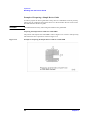
Performing Fixture Compensation . . . . . . . . . . . . . . . . . . . . . . . . . . . . . . . . . . . . . . . . . . . . . . . . . . . . . . . . 43
Measuring the SHORT Compensation Data . . . . . . . . . . . . . . . . . . . . . . . . . . . . . . . . . . . . . . . . . . . . . . . 43
Measuring the OPEN Compensation Data . . . . . . . . . . . . . . . . . . . . . . . . . . . . . . . . . . . . . . . . . . . . . . . . 47
Connecting and Measuring the DUT . . . . . . . . . . . . . . . . . . . . . . . . . . . . . . . . . . . . . . . . . . . . . . . . . . . . . . 48
4. User Maintenance
Description . . . . . . . . . . . . . . . . . . . . . . . . . . . . . . . . . . . . . . . . . . . . . . . . . . . . . . . . . . . . . . . . . . . . . . . . . . 52
Necessity of User Maintenance. . . . . . . . . . . . . . . . . . . . . . . . . . . . . . . . . . . . . . . . . . . . . . . . . . . . . . . . . 52
Cleaning . . . . . . . . . . . . . . . . . . . . . . . . . . . . . . . . . . . . . . . . . . . . . . . . . . . . . . . . . . . . . . . . . . . . . . . . . . . . 54
Areas Requiring Cleaning . . . . . . . . . . . . . . . . . . . . . . . . . . . . . . . . . . . . . . . . . . . . . . . . . . . . . . . . . . . . . 54
Cleaning Method . . . . . . . . . . . . . . . . . . . . . . . . . . . . . . . . . . . . . . . . . . . . . . . . . . . . . . . . . . . . . . . . . . . . 54
Deterioration Check . . . . . . . . . . . . . . . . . . . . . . . . . . . . . . . . . . . . . . . . . . . . . . . . . . . . . . . . . . . . . . . . . . . 56
Example Settings of User Limit Values . . . . . . . . . . . . . . . . . . . . . . . . . . . . . . . . . . . . . . . . . . . . . . . . . . 56
Acquiring Reference Values . . . . . . . . . . . . . . . . . . . . . . . . . . . . . . . . . . . . . . . . . . . . . . . . . . . . . . . . . . . 57
Electrode Deterioration Check . . . . . . . . . . . . . . . . . . . . . . . . . . . . . . . . . . . . . . . . . . . . . . . . . . . . . . . . . 57
Check Sheet . . . . . . . . . . . . . . . . . . . . . . . . . . . . . . . . . . . . . . . . . . . . . . . . . . . . . . . . . . . . . . . . . . . . . . . . . 59
Example Entry in Check Sheet . . . . . . . . . . . . . . . . . . . . . . . . . . . . . . . . . . . . . . . . . . . . . . . . . . . . . . . . . 59
Electrode Deterioration Check . . . . . . . . . . . . . . . . . . . . . . . . . . . . . . . . . . . . . . . . . . . . . . . . . . . . . . . . . 60
Assembly Check . . . . . . . . . . . . . . . . . . . . . . . . . . . . . . . . . . . . . . . . . . . . . . . . . . . . . . . . . . . . . . . . . . . . . . 62
5. Specifications and Supplemental Performance Characteristics
Definitions . . . . . . . . . . . . . . . . . . . . . . . . . . . . . . . . . . . . . . . . . . . . . . . . . . . . . . . . . . . . . . . . . . . . . . . . . . 64
Specifications . . . . . . . . . . . . . . . . . . . . . . . . . . . . . . . . . . . . . . . . . . . . . . . . . . . . . . . . . . . . . . . . . . . . . . . . 65
7
Contents
Supplemental Performance Characteristics . . . . . . . . . . . . . . . . . . . . . . . . . . . . . . . . . . . . . . . . . . . . . . . . . 66
Additional Error . . . . . . . . . . . . . . . . . . . . . . . . . . . . . . . . . . . . . . . . . . . . . . . . . . . . . . . . . . . . . . . . . . . . 66
Residual Inductance of the Shorting Bar . . . . . . . . . . . . . . . . . . . . . . . . . . . . . . . . . . . . . . . . . . . . . . . . . . . 68
6. Service
Replaceable Parts . . . . . . . . . . . . . . . . . . . . . . . . . . . . . . . . . .
Pressure Unit . . . . . . . . . . . . . . . . . . . . . . . . . . . . . . . . . . .
Electrode Unit . . . . . . . . . . . . . . . . . . . . . . . . . . . . . . . . . . .
Other Parts . . . . . . . . . . . . . . . . . . . . . . . . . . . . . . . . . . . . . . . . . . . . . . . . . . . . . . . . . . . . . . . . . . . . . . . .
Changing the Orientation of or Replacing the Contact Assembly . . . . . . . . . . . . . . . .
Procedure for Changing the Orientation of or Replacing the Contact Assembly. . . . . . . . . . . . . . . . . . .
Operation Check. . . . . . . . . . . . . . . . . . . . . . . . . . . . . . . . . . . . . . . . . . . . . . . . . . . . . . . . . . . . . . . . . . . . . .
Open Impedance Check . . . . . . . . . . . . . . . . . . . . . . . . . . . . . . .
Short Impedance Check . . . . . . . . . . . . . . . . . . . . . . . . . . . . . . .
Short-impedance Measurement Repeatability Check. . . . . . . . . . . . . . . . . . . .
70
70
72
73
74
74
76
76
77
77
A. Manual Changes
Manual Changes . . . . . . . . . . . . . . . . . . . . . . . . . . . . . . . . . . . . . . . . . . . . . . . . . . . . . . . . . . . . . . . . . . . . . . 80
8
1
Installation Guide
This chapter describes the necessary operations to perform before using the delivered
bottom-electrode SMD test fixture 16197A.
9
Installation Guide
Inspection before Unpacking
Inspection before Unpacking
Upon receiving the product package, inspect the packing box before unpacking to make
sure it is not damaged. If the packing box or packing materials have been damaged, keep
the box and materials until it has been confirmed that all necessary components have been
delivered and that product operation is normal both mechanically and electrically.
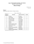
Check the package contents against Table 1-1. If any component is missing, or
mechanically damaged or defective, please contact Agilent Technologies local sales office.
If the packing box has been damaged or the packing materials have been severely
deformed, please contact the freight company as well as our sales office. Until the freight
company carries out its inspection, store the packing box and materials as they are, with all
product components left inside.
NOTE
Before using this product for the first time after delivery, carry out “Deterioration Check”
on page 56, which is necessary to ensure accurate measurement. For details, see
“Acquiring Reference Values” on page 57 of the “Deterioration Check” section.
10
Chapter 1
Installation Guide
Inspection before Unpacking
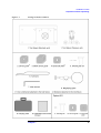
Figure 1-1
Package Contents of 16197A
Chapter 1
11
Installation Guide
Inspection before Unpacking
Table 1-1
Package Contents of 16197A
No.
Name
Agilent part
number
Qty
1
Bottom-electrode SMD test fixture 16197A
-
1
2
Device guide*1
16197-25005
2
3
Blank device guide
16197-25006
3
4
Electrode plate*2
16197-00603
1
5
EIA/EIAJ -size, Shorting bar set
Shorting bar 1.0 × 0.5 × 0.5*3
16191-29005
1
Shorting bar 1.6 × 0.8 × 0.8*3
16191-29006
1
Shorting bar 2.0 × 1.2 × 0.8*3
16191-29007
1
Shorting bar 3.2 × 1.6 × 0.8*3
16191-29008
1
6
Tweezers
8710-2081
1
7
Allen wrench
8710-0909
1
8
Magnifying glass
16193-60002
1
9
Carrying case
16197-60050
1
10
Operation and service manual (this manual)
16197-97000
1
Option 001
11
Shorting bar 0.6 × 0.3 × 0.3
16197-29001
4
12
Device guide
16197-25007
1
13
Electrode plate
16197-00604
1
*1.One is Delivered attached to the test fixture
*2.Delivered attached to the test fixture
*3.Shorting bars are delivered together in one case.
12
Chapter 1
Installation Guide
Assembly and Storage of 16197A
Assembly and Storage of 16197A
The 16197A is delivered in a carrying case, disassembled into a pressure unit and an
electrode unit. Assemble the fixture before use. Disassemble the fixture when storing it in
the carrying case.
Assembly of 16197A
Before using the 16197A, install the pressure unit onto the electrode unit as shown in
Figure 1-2.
Figure 1-2
Installing the Pressure Unit
Chapter 1
13
Installation Guide
Assembly and Storage of 16197A
Installing the Magnifying Glass
If the magnifying glass is used, install it on the edge of the electrode unit as shown in
Figure 1-3.
Figure 1-3
Installing the Magnifying Glass
14
Chapter 1
Installation Guide
Assembly and Storage of 16197A
Storage
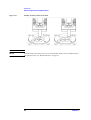
Before storing the 16197A, remove the pressure unit from the electrode unit (Figure 1-4),
and loosen the pressure adjusting nut on the pressure unit (Figure 1-5). Also remove the
magnifying glass, if installed.
Figure 1-4
Removing the Pressure Unit
Figure 1-5
Pressure Adjusting Nut
Chapter 1
15
Installation Guide
Changing the Positions of the Guide Holder Fixing Screws
Changing the Positions of the Guide Holder Fixing Screws
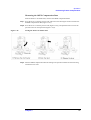
If the guide holder fixing screws hamper operation, the positions of these screws can be
changed.
Figure 1-6
Positions of the Guide Holder Fixing Screws
Method for Changing the Positions of the Guide Holder Fixing Screws
Before changing the positions of the fixing screws, remove the pressure unit.
Step 1. Remove the four screws that fix the guide holder flange (Figure 1-7).
Step 2. Rotate the guide holder by 90 degrees together with the components fixed on the flange,
and again set the guide holder in place (Figure 1-7).
16
Chapter 1
Installation Guide
Changing the Positions of the Guide Holder Fixing Screws
Figure 1-7
Changing the Positions of the Guide Holder Fixing Screws
Chapter 1
17
Installation Guide
Connecting the Test Fixture with a Measuring Instrument
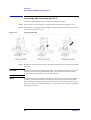
Connecting the Test Fixture with a Measuring Instrument
Connecting the test fixture 16197A with a measuring instrument requires an adapter suited
to the instrument.
The test fixture 16197A is suitable for use with a high-frequency LCR meter or an
impedance analyzer. Table 1-1 shows possible adapter combinations.
Table 1-2
Adapter for a Measuring Instrument with a 7-mm
Connector
Measuring instrument
Adapter
4287A
Test head + Test fixture stand (supplied with the 4287A)
4291A/B
Test station + Test head (supplied with the 4291A/B)
4286A
Test head + Test fixture stand (supplied with the 4286A)
4395A *1
43961A impedance test adapter
4396B *1
43961A impedance test adapter
E4991A
Test head (supplied with the E4991A)
*1. The measuring instrument requires the "Option 010 impedance measurement function".
The test fixture 16197A can also be connected with any measuring instrument with
4-terminal pair configuration if an appropriate adapter is used.
Table 1-3
Adapter for a Measuring Instrument with 4-terminal
Pair Configuration
Measuring instrument
Adapter
4294A
42942A terminal adapter
4194A
41941A+ 16099A or 41941B+ 16099A
4192A, 4194A,
4263B, 4268A,
4278A, 4279A,
4284A, 4285A,4288A
16085B terminal adapter
For the procedure for attaching an adapter, see the Operation Manual for the adapter.
NOTE
Calibration on the 7-mm connector surface may be necessary depending on the type of
measuring instrument. In such a case, perform calibration on the 7-mm connector surface
before connecting the test fixture with the measuring instrument. For details, see the
Operation Manual for the measuring instrument.
18
Chapter 1
Installation Guide
Connecting the Test Fixture with a Measuring Instrument
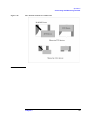
Below is the general procedure for attaching an adapter to the test fixture. (For details, see
the Operation Manual for each adapter.)
Step 1. Rotate the 7-mm connector on the adapter counterclockwise as viewed from above to
completely retract the connecting sleeve.
Step 2. Gently place the test fixture onto the adapter, aligning the mounting holes with the
mounting posts on the adapter, and the 7-mm connector with that on the adapter.
Step 3. Rotate the 7-mm connector on the adapter counterclockwise as viewed from above to
connect it with the connector on the bottom of the test fixture.
NOTE
Turn the 7-mm connector on the adapter using a 3/4-inch torque wrench with 12 lb-inch
torque (Agilent part number: 8710-1766) to firmly connect the test fixture.
Figure 1-8
Installing the Test Fixture
Chapter 1
19
Installation Guide
Connecting the Test Fixture with a Measuring Instrument
20
Chapter 1
2
Product Description
21
Product Description
Product Description
Product Description
The 16197A is a test fixture for use in measuring bottom-electrode chip components. It
enables highly accurate and repeatable measurement of chip-type capacitors, inductors,
and other similar components. The 16197A is compatible with measuring frequencies to 3
GHz, and can accommodate bottom-electrode chip components of sizes 3225 *1(1210*2),
3216(1206*2), 2012 *1(0805*2), 1608 *1(0603*2), and 1005 *1(0402*2). Measurement of
chip components of other sizes is possible by preparing appropriate device guides.
Measurement of a bottom-electrode chip component of size 0603 *1(0201*2) is also
possible using the option.
Figure 2-1
Product Appearance
*1.EIAJ size
*2.EIA size
22
Chapter 2
Product Description
Product Description
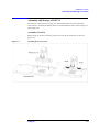
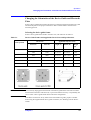
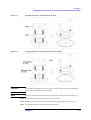
Mechanism for Connecting a DUT (Device Under Test)
The 16197A uses a device guide and an electrode plate for measuring to various sizes of
bottom-electrode SMDs.
The electrode plate is placed onto the center electrode of the electrode unit, producing four
different electrode spaces between the center electrode and electrode plate (Figure 2-2).
Figure 2-2
Structure of Electrode (1)
The device guide is placed on the electrode plate to enable each DUT to be positioned in a
fixed location (Figure 2-3). Each DUT is set in a frame of the size suitable to the DUT for
connecting to the electrode (Figure 2-4).
Figure 2-3
Structure of Electrode (2)
Chapter 2
23
Product Description
Product Description
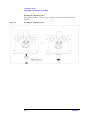
Figure 2-4
Connecting a DUT
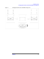
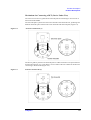
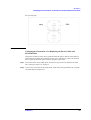
The DUT is to be fixed under pressure from the pressure rod. Since the movable range of
the pressure rod is limited, either one of the two lateral frames in the device guide can be
used as the measuring position (Figure 2-5). Therefore, before connecting a DUT, it may
be necessary to change the orientation of the electrode plate and device guide set in place
so that the appropriate electrode and device guide frame arrive at the measuring position.
Figure 2-5
Measuring Position for Each Device Size
24
Chapter 2
Product Description
Product Description
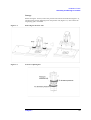
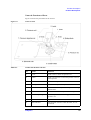
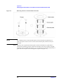
Names & Functions of Parts
Figure 2-6 shows the part names for the 16197A.
Figure 2-6
Names of Parts
Table 2-1
Names & Functions of Parts
No.
Name
Function
1
Lever
Used to raise or lower the pressure rod
2
Latch
Used to fix the lever to retain the pressure rod in its
raised position
3
Knob
Used to fix the pressure unit
4
Sliding block
Used to laterally move the pressure unit
5
Pressure rod
Used to fix the DUT by downward pressure during
measurement
6
Guide holder
Used to fix the electrode plate and device guide
7
Pressure adjusting nut
Used to adjust the DUT-retaining pressure of the
pressure rod
8
Pressure unit
Apparatus to retain the DUT, etc.
9
Electrode unit
The electrode section to which the DUT, etc. are
connected
Chapter 2
25
Product Description
Product Description
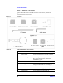
Names & Functions of Accessories
Figure 2-7 shows the names of standard accessories for the 16197A, and those of
accessories available in Option 001.
Figure 2-7
Accessories
Table 2-2
Names & Functions of Accessories
No.
Name
Function
1
Device guide*1
Used to position the DUT, etc. when connecting
it to the electrode
2
Blank device guide
Used to prepare a device guide frame suited to a
DUT of a size not fitting any frame in the
attached device guide
3
Electrode plate*1
Used to create various electrode spaces
4
Shorting bar set
Shorting bars in EIA/EIAJ sizes, and a case for
storing them. These bars are used during of
SHORT compensation.
5
Tweezers
Used to handle shorting bars, the DUT, etc.
6
Allen wrench
Used to tighten/loosen hexagonal nuts
26
Chapter 2
Product Description
Product Description
Table 2-2
Names & Functions of Accessories
No.
Name
Function
7
Magnifying glass
Used to magnify the view of a connector,
electrode, etc.
Option 001
8
Device guide
Device guide for 0603 devices
9
Electrode plate
Electrode plate for 0603 devices
10
Shorting bar
Shorting bars for 0603 devices, and a case for
storing them. These bars are used during SHORT
compensation.
*1.Delivered attached to the electrode unit
Chapter 2
27
Product Description
Product Description
28
Chapter 2
3
Operation
This chapter describes the procedures for measurement preparation, fixture compensation,
connection of a DUT, and measurement with the 16197A.
29
Operation
Measurement Flow
Measurement Flow
To measure a DUT by taking measurements with the 16197A, follow the procedure below.
1. Setting the measuring conditions
Set the measuring conditions for the measuring instrument to be used.
2. Performing calibration
Calibrate the measuring instrument and adapters, if necessary.
3. Setting the electrical length
Set the electrical length for the measuring instrument, if necessary.
4. Changing the orientation of the device guide and electrode plate
Select a device guide frame that fits the configuration of the DUT, and change the
orientation of the device guide and electrode plate set on the center electrode, if
necessary.
5. Performing fixture compensation
Measure the SHORT compensation and OPEN compensation data.
6. Connecting and measuring the DUT
Connect the DUT to the fixture and perform the measurement.
WARNING
The 16197A has the capability for -55°C to +85°C temperature measurement in
environmental testing. Use gloves to prevent burns when handling heated parts.
30
Chapter 3
Operation
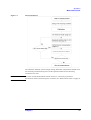
Measurement Flow
Figure 3-1
Measurement Flow
The calibration methods, electrical length setting, and fixture compensation all differ with
the measuring instrument being used. See the operation manual for the measuring
instrument to be used.
NOTE
To ensure accurate measurement with the 16197A, it is necessary to perform a
deterioration check of the shorting bars. For details, see “Deterioration Check” on page 56.
Chapter 3
31
Operation
Setting the Electrical Length
Setting the Electrical Length
Set the electrical length for the measuring instrument, if necessary. For the method of
setting the electrical length, see the operation manual for the measuring instrument. The
electrical length for the 16197A is as follows:
32
Model
Electrical length [mm]
16197A
14.00 mm
Chapter 3
Operation
Changing the Orientation of the Device Guide and Electrode Plate
Changing the Orientation of the Device Guide and Electrode
Plate
Select a device guide frame suited to the DUT size, and mount the appropriate device guide
and electrode plate in the proper orientation so that a suitable frame is located at the
measuring position.
Selecting the device guide frame
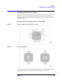
Select a device guide frame suited to the DUT size, with reference to Table 3-1.
Table 3-1
Device Guide Frames and Applicable Device Sizes and Specifications
Device size
Applicable chip size (mm)
Frame position
EIAJ size
EIA size
Length (L)
Width (W)
Height
(H)
3225
1210
3.2 ± 0.15
2.5 ± 0.15
≥ 0.4
3216
1206
3.2 ± 0.15
1.6 ± 0.15
≥ 0.4
3
2012
0805
2.0 ± 0.15
1.25 ± 0.15
≥ 0.4
2
1608
0603
1.6 ± 0.15
0.8 ± 0.15
≥ 0.4
4
1005
0402
1.0 ± 0.15
0.5 ± 0.15
≥ 0.4
5
0603
0201
0.6 ± 0.03
0.3 ± 0.03
≥ 0.25
1
NOTE
An excessively large gap between the DUT and device guide frame will result in contact
failure between the DUT and electrode, or poor measurement accuracy or repeatability. Be
sure to select a device guide frame that fits the DUT configuration.
If the DUT size does not fit any frame in the attached device guide, prepare a suitable
frame using the supplied blank device guide. For details, see “Working with the Device
Guide”.
Chapter 3
33
Operation
Changing the Orientation of the Device Guide and Electrode Plate
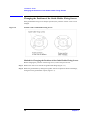
Figure 3-2
Electrode Spacing
Figure 3-3
Dimensions of the Device Guide Frame
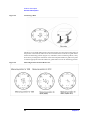
CAUTION
Be sure to superpose the device guide onto the electrode plate in the proper orientation and
with the correct side facing up. Otherwise, adequate electrode spacing cannot be created.
As shown in Figure 3-3, when viewed from above, on the correct face of the device guide
there are two marks at positions 90 degrees apart clockwise from a single position.
Superpose the device guide onto the electrode plate so that all these marks are aligned with
the corresponding marks on the electrode plate. For a 0603 device, superpose the device
guide onto the electrode plate so that one mark is aligned with the corresponding mark on
34
Chapter 3
Operation
Changing the Orientation of the Device Guide and Electrode Plate
the electrode plate.
Changing the Orientation of or Replacing the Device Guide and
Electrode Plate
Change the orientation of the device guide and electrode plate so that the selected device
guide frame is located at the measuring position. For a 0603 device, replace the attached
device guide and electrode plate with ones supplied in Option 001.
Step 1. Loosen the knobs on the sliding block, and remove the pressure unit from the electrode
unit, referring to Figure 1-4 on page 15.
Step 2. Unscrew the screws that fix the guide holder. Then remove the guide holder, device guide,
and electrode plate (Figure 3-4).
Chapter 3
35
Operation
Changing the Orientation of the Device Guide and Electrode Plate
Figure 3-4
Removing the Device Guide and Electrode Plate
NOTE
If it is difficult to take out the electrode plate, turn the electrode unit upside down to
remove the plate. Do not use force to take out the electrode plate, otherwise it may be
deformed.
Step 3. Mount the device guide and electrode plate so that the selected device guide frame is
located at the measuring position. Ensure that the marks on the device guide are aligned
with those on the electrode plate (Figure 3-5). For a 0603 DUT, replace the attached device
guide and electrode plate with ones supplied in Option 001 (Figure 3-6).
36
Chapter 3
Operation
Changing the Orientation of the Device Guide and Electrode Plate
Figure 3-5
Mounting the Device Guide and Electrode Plate
Figure 3-6
Mounting the Device Guide and Electrode Plate for 0603
CAUTION
Do not touch or damage the center electrode or electrode plate, otherwise measurement
accuracy and repeatability may be impaired.
NOTE
Be sure to mount the device guide and electrode plate with the correct sides facing up.
Step 4. Install the guide holder, and tighten the screws to secure it.
Step 5. Mount the pressure unit onto the electrode unit according to Figure 1-2 on page 13.
Step 6. Connect the test fixture with the measuring instrument.
Chapter 3
37
Operation
Changing the Orientation of the Device Guide and Electrode Plate
Connect the test fixture with the measuring instrument according to “Connecting the Test
Fixture with a Measuring Instrument” on page 18 in Chapter 1.
38
Chapter 3
Operation
Working with the Device Guide
Working with the Device Guide
To measure a DUT whose size does not fit any frame in the attached device guide, it is
necessary to prepare a suitable device guide frame. Prepare a frame with reference to the
dimensions of the blank device guide shown in Figure 3-7 and the electrode positioning
shown in Figure 3-8.
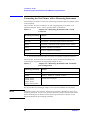
Reference Data for Preparing a Device Guide Frame
Figure 3-7
Dimensional Drawing of a Blank Device Guide
Figure 3-8
Electrode Positioning
A guide holder is placed onto the device guide. Figure 3-9-A shows the inside diameter of
the guide holder. Figure 3-9-B shows the movable range of the pressure rod.
Chapter 3
39
Operation
Working with the Device Guide
Figure 3-9
Inside Diameter of Guide Holder & Movable Range of Pressure Rod
Determine the position of the frame to be prepared, keeping in mind the following
requirements:
•
The electrode of the DUT must maintain equal contact with both the center electrode
and electrode plate.
•
The electrode of the DUT must have a large contact area, and the electrode space
between the center electrode and electrode plate must be as large as possible.
•
The pressure rod must be able to press the center of the DUT to stabilize the DUT
during measurement.
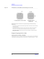
Example of Preparing the Device Guide
Preparing the Device Guide for a 2520 SMD
The figure below shows an example of preparation for a device guide for a 2520 SMD. For
a 2520 SMD, the measuring position for a 2012 device is used (electrode space: 1.5 mm).
40
Chapter 3
Operation
Working with the Device Guide
Figure 3-10
Example of Preparation of Device Guide for 2520 SMD
Prepare the frame at the position shown in Figure 3-10. This position is within the movable
range of the pressure rod (4 mm on each lateral side from the center). In a frame at this
position, the electrodes on both lateral sides of the DUT can be placed in equal contact by
0.4-mm width with the center electrode and the electrode plate.
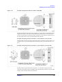
Example of Preparing the Device Guide for an SOT 23 Device (Case Style 287)
The figure below shows an example of preparing a device guide for an SOT 23 device. For
an SOT 23 device, the measuring position for a 1608 device is used (electrode space: 1.0
mm).
Figure 3-11
Example of Preparing the Device Guide for an SOT 23 Device (Case Style 287)
Prepare a frame at the position shown in Figure 3-11. In a frame at this position, the
electrodes on both lateral sides of the DUT can be placed in equal contact by 0.6-mm width
with the center electrode and the electrode plate.
Chapter 3
41
Operation
Working with the Device Guide
Example of Preparing a Simple Device Guide
In order to prepare the device guide more easily, there is a method that involves precisely
cutting only the 2 sides that position the device over the electrodes. Do not cut the corner
hole which mounts the device guide.
CAUTION
The measurement accuracy when using this method is not guaranteed.
Preparing the Simple Device Guide for a 2520 SMD
The position which places the 2520 SMD is same as Figure 3-10. Cut the 2 sides precisely
which fixes the device position as shown in Figure 3-12.
Figure 3-12
Example of Preparing the Simple Device Guide for a 2520 SMD
42
Chapter 3
Operation
Performing Fixture Compensation
Performing Fixture Compensation
To ensure accurate measurement, it is necessary to perform fixture compensation before
measurement. For the 16197A, measure the SHORT compensation and OPEN
compensation data. If the DUT size or the measuring position is changed, perform fixture
compensation again.
NOTE
If a temperature change greater than ± 5°C occurs after fixture compensation, perform the
fixture compensation from the beginning.
Measuring the SHORT Compensation Data
With the fixture SHORT state using a supplied shorting bar, measure the SHORT
compensation data.
Step 1. Rotate the pressure adjusting nut to adjust the pressure on the pressure rod to the same
value as used for measurement.
Step 2. Loosen the knobs on the sliding block, and adjust the position of the pressure unit so that
the end of the pressure rod is located at the center of the device guide frame where the
shorting bar will be placed (Figure 3-13).
Figure 3-13
Adjusting the Pressure Unit Position
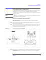
Step 3. Press the lever to the limit (Figure 3-14,1). With the lever pressed, push in the latch (Figure
3-14,2), and then release the lever(Figure 3-14,3). The pressure rod is then fixed at its
raised position.
Chapter 3
43
Operation
Performing Fixture Compensation
Figure 3-14
Raising the Pressure Rod
Step 4. Using tweezers, place an appropriate shorting bar on the electrode along the device guide
frame.
CAUTION
Each shorting bar is made exclusively for a particular device size. Do not use a shorting bar
of the wrong size.
Figure 3-15
Connecting the Shorting Bar
CAUTION
Handle each shorting bar with tweezers, taking care not to soil it. A soiled shorting bar may
impair measurement accuracy and repeatability.
NOTE
Take care so that the correct face of the shorting bar is placed in contact with the electrode.
NOTE
Shorting bars can wear out. Therefore, each time before using a shorting bar, measure and
compare its resistance with that of a new shorting bar. For details, see “Operation Check”
44
Chapter 3
Operation
Performing Fixture Compensation
on page 76.
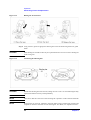
Step 5. Press the lever; the latch is disengaged (Figure 3-16,1). Slowly release the lever to lower
the pressure rod (Figure 3-16,2).
Figure 3-16
Setting the Fixture for SHORT State Using a Shorting Bar
NOTE
Adjust the position of the pressure unit in advance so that a shorting bar can be pressed at
its center by the end of the pressure rod.
Step 6. Measure the SHORT compensation data according to the operation manual for the
measuring instrument to be used.
NOTE
When measurement is not being done, lower the pressure rod so it rests on an unoccupied
area of the device guide.
Chapter 3
45
Operation
Performing Fixture Compensation
Figure 3-17
Standby Position of the Pressure Rod
NOTE
Confirm that the end of the pressure rod is not deformed. Replace the rod if deformed. For
the replacement part, see “Replaceable Parts” on page 70.
46
Chapter 3
Operation
Performing Fixture Compensation
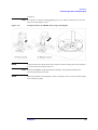
Measuring the OPEN Compensation Data
With the fixture in an OPEN state, measure the OPEN compensation data.
Step 7. Press the lever to raise the pressure rod, and remove the shorting bar used to measure the
SHORT compensation data (Figure 3-18,1).
Step 8. Press the lever to raise the pressure rod (Figure 3-18,2), and push the latch to secure the
pressure rod in its raised position (Figure 3-18,3).
Figure 3-18
Setting the Fixture for OPEN State
Step 9. Measure OPEN compensation data according to the operation manual for the measuring
instrument to be used.
Chapter 3
47
Operation
Connecting and Measuring the DUT
Connecting and Measuring the DUT
Connect the DUT with the electrode, and carry out the measurement.
Step 1. Place the DUT on the electrode in an appropriate device guide frame (Figure 3-19,1).
Step 2. Press the lever to disengage the latch (Figure 3-19,2), and slowly release the lever to lower
the pressure rod (Figure 3-19,3).
Figure 3-19
Connecting the DUT
Step 3. Perform the measurement according to the operation manual for the measuring instrument
to be used.
CAUTION
The DUT may become hot during measurement. If the temperature of the DUT rises, the
end of the pressure rod may be deformed. If this occurs, decrease the pressure on the
pressure rod to prevent deformation of the end of the rod.
NOTE
To ensure accurate and repeatable measurements, place the DUT alongside a fixed edge of
each device guide frame. Testing a 3216 DUT, for instance, uses the 3216/3225 frame.
Since this frame is dimensioned to fit with a 3225 device, some clearance remains in the
frame if it is used for a 3216 DUT. Therefore, it is necessary to place the DUT alongside a
fixed edge of the frame.
48
Chapter 3
Operation
Connecting and Measuring the DUT
Figure 3-20
DUT Position in the Device Guide Frame
Chapter 3
49
Operation
Connecting and Measuring the DUT
50
Chapter 3
4
User Maintenance
This chapter describes the operations to perform before starting measurement, and the
procedures necessary to ensure accurate measurements.
51
User Maintenance
Description
Description
Necessity of User Maintenance
Through repeated use, the fixture's measuring performance will gradually deteriorate over
time due to smearing on the contact faces from solder buildup, and to mechanical wear and
deformation of the contact faces themselves. To continually achieve optimal measurement
results, it is important to keep the contact faces in good condition and take appropriate
action before such wear or deformation occurs. Therefore, the fixture should be properly
cared for by implementing each of the maintenance items shown in Table 4-1.
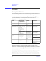
Table 4-1
Maintenance Items
Name
Frequency of
implementation
Contents
Target parts
Cleaning
Several times a day
Cleaning the
fixture
Entire fixture
Electrode
deterioration check
Before using the
fixture for the first
time after
delivery/After
replacement of
parts
Acquisition of
reference values*1
Center electrode,
Electrode plate
Once a day/Before
fixture
compensation
Determining the
deviation from
reference values*1
Center electrode,
Electrode plate
When deterioration
check result is
unacceptable
Changing the
orientation of the
contact assembly,
or replacement of
parts
Center electrode,
Electrode plate
After replacement
of parts
Evaluation of
absolute Ls and
Rs values
Center electrode,
Electrode plate
Replacement of
parts
Assembly check
Shorting bar
Shorting bar
*1. For details, see "Acquiring Reference Values" on page 57.
Maintenance of the fixture is important especially to ensure fine or highly accurate
measurement, since deteriorated measurement performance of the fixture has a significant
effect on the measurement results. Depending on the required measurement performance, it
may be necessary to increase the frequency of maintenance and/or adopt more strict criteria
for each maintenance item.
The electrodes and shorting bars are consumable. Of all the fixture components, these parts
are most likely to affect the measurement results. The electrodes tend to deteriorate
gradually since they can easily be smeared with solder transferred from the DUT during
measurements. Because shorting bars are used to determine the zero reference for fixture
52
Chapter 4
User Maintenance
Description
compensation, smeared or deformed shorting bars can directly influence measurement
results. This chapter describes the general user maintenance requirements, focusing
primarily on the electrodes and shorting bars.
Chapter 4
53
User Maintenance
Cleaning
Cleaning
Smeared electrodes result in poor measurement accuracy and repeatability. Periodically
clean the electrodes to ensure accurate measurements.
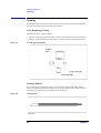
Areas Requiring Cleaning
The following areas require cleaning.
•
•
Figure 4-1
The area of the center electrode that will be in contact with the electrode of the DUT
The area of the electrode plate that will be in contact with the electrode of the DUT
Areas Requiring Cleaning
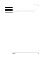
Cleaning Method
Use a cleaning rod (Agilent part number: 5182-7586) to clean the electrodes. Remove
smeares on the above-mentioned contact area by wiping with the white rubber portion of
the cleaning rod. Take care not to damage the electrode parts.
Figure 4-2
Cleaning Rod
54
Chapter 4
User Maintenance
Cleaning
CAUTION
Do not file off the smeares; filing part surfaces may cause poor measurement accuracy or
repeatability.
NOTE
If smeares cannot be removed, replace the part. For the replacement method, see
"Changing the Orientation of or Replacing the Contact Assembly" on page 74.
Chapter 4
55
User Maintenance
Deterioration Check
Deterioration Check
A deterioration check must be performed to determine the state of deterioration of the
fixture and to confirm whether the fixture is providing the required measurement accuracy.
The deterioration check comprises three operations: "Setting user limit values," “Acquiring
Reference Values”“Electrode Deterioration Check”. In the deterioration check, the
impedance values (Rs, Ls) of the fixture itself are measured at a discretionary frequency. It
is recommended to use the frequency at which the fixture is normally used.
Perform "Setting user limit values" in the following cases:
•
•
When using the fixture for the first time after delivery
When changing the required measurement accuracy
Perform “Acquiring Reference Values” in the following cases:
•
•
When using the fixture for the first time after delivery
After replacing parts
Perform “Electrode Deterioration Check” in the following cases:
•
Once a day, and before conducting fixture compensation
Example Settings of User Limit Values
User limit values for the deterioration check should be set appropriately according to the
type of DUT, required measurement accuracy, and so on. Example settings of user limit
values are shown below.
To evaluate an inductor (L: 10 nH, Q: 10) at a frequency (f) of 100 MHz with a
measurement accuracy of around 20%:
L:
10 nH
Q:
10
Frequency:
100 MHz
Required measurement accuracy:
20% for both L and Q
The reactance X and resistance R of the inductor under the above-mentioned conditions
can be obtained as follows:
R = X ⁄ Q = 0.6 Ω
X = 2πfL = 6 Ω
Therefore, Q = X ⁄ R = 2πfL ⁄ R . Accordingly, if R fluctuates by 20% (120 mΩ), Q will
change by about 20%; and if L fluctuates by 20% (2 nH), both L and Q will change by
about 20%. In other words, to measure L and Q at an accuracy of 20% or less error, errors
in L and R must be 2 nH and 120 m Ω at the most, respectively. Considering that both L
and R may fluctuate, and allowing for possible causes of error other than a deteriorated
fixture, the errors must be set smaller than the above-mentioned values. For the present
example, with the error set at 25% for both L and R, the user limit values for L and R are
set at 500 pH and 30 mΩ, respectively.
56
Chapter 4
User Maintenance
Deterioration Check
NOTE
Note that the above settings are just an example. Actually, user limit values should be
varied depending on the measuring conditions and type of DUT.
NOTE
In actual measurement, some of the effect of electrode deterioration is canceled by SHORT
compensation. However, it is recommended to set user limit values on the assumption that
deviations from the reference values affect the entire measurement results, as shown in the
above example.
Record the user limit values in the “Check Sheet” on page 60. For the method of recording,
see "Example Entry in Check Sheet" on page 59.
Acquiring Reference Values
To obtain reference values, measure the impedance (Rs, Ls) of the fixture before
deterioration. It is recommended to take measurements at a frequency at which the fixture
is normally used. It is necessary to obtain reference values using electrodes and shorting
bars for all sizes of DUTs that will be subject to actual measurement.
"Acquiring reference values" is necessary in the following cases:
•
•
When using the fixture for the first time after delivery
After replacement of parts
Necessary
equipment
•
•
Shorting bars (supplied as accessories)
Impedance measuring instrument (calibrated at the 7-mm connector end)
CAUTION
Set the fixture compensation for the measuring instrument to OFF.
CAUTION
Check that each shorting bar is not deformed or stained.
Procedure for Acquiring Reference Values for the Electrode Deterioration Check
Step 1. Clean each electrode and shorting bar using the method described in "Cleaning" on
page 54.
Step 2. At the actual DUT measurement position, connect an appropriate shorting bar with the
electrode to set the fixture for the SHORT state (See Figure 3-16 on page 45).
Step 3. Measure Rs and Ls according to the Operation and Service Manual for the measuring
instrument.
Step 4. Record the Rs and Ls readings as reference values in the “Check Sheet” on page 59.
Step 5. From the reference values and the user limit values determined in the preceding section,
calculate the upper and lower limit values, and record them in the Check Sheet.
Electrode Deterioration Check
Measure the impedance of the fixture in the SHORT state to check for electrode
deterioration. Use a shorting bar suited to the size of the actual DUT.
The electrode deterioration check is necessary in the following cases:
Chapter 4
57
User Maintenance
Deterioration Check
•
Once a day, and before conducting fixture compensation
Necessary
equipment
•
•
Shorting bars (supplied as accessories)
Impedance measuring instrument (calibrated at the 7-mm connector end)
CAUTION
Set the fixture compensation of the measuring instrument to OFF. Set all other functions to
the same states according to "Acquiring Reference Values."
Electrode Deterioration Check Procedure
Step 1. Clean each electrode and shorting bar using the method described in "Cleaning" on
page 54.
Step 2. Perform the measurement, with the measuring instrument set for the same conditions as
mentioned in "Procedure for Acquiring Reference Values for the Electrode Deterioration
Check" on page 57.
Step 3. Record the Rs and Ls readings, as well as their acceptability, in the “Check Sheet” on
page 59.
Step 4. If the results are unacceptable, replace the center electrode or the electrode plate.
CAUTION
By changing the orientation of the contact assembly, it is possible to take measurements
using an unused clean area of the center electrode. For details, see "Changing the
Orientation of or Replacing the Contact Assembly" on page 74.
CAUTION
An electrode deterioration check using a deformed or stained shorting bar may produce
unacceptable check results. Replace the shorting bar if it is deformed or if it cannot be
cleaned.
58
Chapter 4
User Maintenance
Check Sheet
Check Sheet
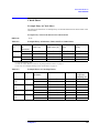
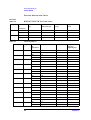
Example Entry in Check Sheet
The following tables show an example entry of electrode deterioration check results in the
Check Sheet.
Example Entry of Electrode Deterioration Check Results
DUT size
2012
Table 4-2
Example Entry of Reference Values and User Limit Values
User
limit value*3 [b]
Lower limit
[a-b]
Upper limit
[a+b]
Frequenc
y*1
Measureme
nt
parameter
Reference
value*2 [a]
100 MHz
Rs
40
30
mΩ
10 mΩ
70 mΩ
Ls
2.34
nH
0.5
nH
1.84
nH
2.84
nH
Rs
220
mΩ
40
mΩ
180
mΩ
260
mΩ
Ls
2.32
nH
0.4
nH
1.92
nH
2.72
nH
800 MHz
mΩ
*1.User's discretionary value
*2.Enter the values obtained in section "Acquiring Reference Values" on page 57.
*3.For entry, see "Example Settings of User Limit Values" on page 56.
Table 4-3
Example Entry of Checking History
Date/Time
Frequenc
y
Measurement
parameter
Measurement value
Acceptability
2000/10/11
9:30
100 MHz
Rs
50 mΩ
O
Ls
2.5 nH
O
2000/10/11
9:35
800 MHz
Rs
250 mΩ
O
Ls
2.6 nH
O
2000/10/12
9:30
100 MHz
Rs
55 mΩ
O
Ls
2.6 nH
O
2000/10/12
9:35
800 MHz
Rs
285 mΩ
X*1
Ls
2.7 nH
O
Set position
of pressure
adjusting nut
*1.Replace parts if check results are not acceptable.
Chapter 4
59
User Maintenance
Check Sheet
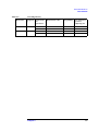
Electrode Deterioration Check
DUT size
______________________
Table 4-4
Reference Values and User Limit Values
Frequenc
y
Measureme
nt
parameter
Reference value
[a]
User
limit value [b]
Lower limit
[a-b]
Upper limit
[a+b]
Rs
mΩ
mΩ
mΩ
mΩ
Ls
pH
pH
pH
pH
Rs
mΩ
mΩ
mΩ
mΩ
Ls
pH
pH
pH
pH
Table 4-5
Date/Time
Checking History
Frequenc
y
60
Measureme
nt
parameter
Measurement value
Rs
mΩ
Ls
pH
Rs
mΩ
Ls
pH
Rs
mΩ
Ls
pH
Rs
mΩ
Ls
pH
Rs
mΩ
Ls
pH
Rs
mΩ
Ls
pH
Rs
mΩ
Ls
pH
Rs
mΩ
Ls
pH
Rs
mΩ
Ls
pH
Rs
mΩ
Ls
pH
Rs
mΩ
Ls
pH
Rs
mΩ
Ls
pH
Acceptability
Set position of
pressure
adjusting nut
Chapter 4
User Maintenance
Check Sheet
Table 4-5
Date/Time
Checking History
Frequenc
y
Chapter 4
Measureme
nt
parameter
Measurement value
Rs
mΩ
Ls
pH
Rs
mΩ
Ls
pH
Acceptability
Set position of
pressure
adjusting nut
61
User Maintenance
Assembly Check
Assembly Check
Each time after replacing a part, conduct an assembly check to confirm that the fixture has
been assembled properly. The procedure for performing an assembly check is identical
with that for an operation check. For the procedure, see "Operation Check" on page 76 in
Chapter 6.
62
Chapter 4
5
Specifications and Supplemental
Performance Characteristics
This chapter provides specifications and supplemental performance characteristics of the
16197A test fixture.
63
Specifications and Supplemental Performance Characteristics
Definitions
Definitions
Specification (spec.): Warranted performance. Specifications include guardbands to
account for the expected statistical performance distribution,
measurement uncertainties, and changes in performance due to
environmental conditions.
Supplemental Information is intended to provide information useful in applying the
instrument, but that is not covered by the product warranty. The information is denoted as
typical, or nominal.
Typical (typ.):
Expected performance of an average unit which does not include
guardbands.
Nominal (nom.):
A general, descriptive term that does not imply a level of
performance.
64
Chapter 5
Specifications and Supplemental Performance Characteristics
Specifications
Specifications
Applicable Instruments
Refer to the Table 1-2 and Table 1-3 on page 18.
Applicable DUT Type
Surface Mount Device with bottom electrodes.
Applicable DUT Size
Model
Length (L) × Width (W) × Height (H)
3225
( 3.2 ± 0.15 ) × ( 2.5 ± 0.15 ) × ( ≥ 0.4 ) mm
3216
( 3.2 ± 0.15 ) × ( 1.6 ± 0.15 ) × ( ≥ 0.4 ) mm
2012
( 2.0 ± 0.1 ) × ( 1.25 ± 0.1 ) × ( ≥ 0.4 ) mm
1608
( 1.6 ± 0.15 ) × ( 0.8 ± 0.15 ) × ( ≥ 0.4 ) mm
1005
( 1.0 ± 0.03 ) × ( 0.3 ± 0.03 ) × ( ≥ 0.4 ) mm
0603
( 0.6 ± 0.03 ) × ( 0.3 ± 0.03 ) × ( ≥ 0.25) mm
Frequency
DC to 3 GHz
Maximum Voltage
± 40V peak max. (AC+DC)
Maximum Current
5A
Operating
Environment
temp.
-55°C to +85°C
humidity
15% to 95%RH (@ wet bulb temp. < 40°C)
Non Operating
temp.
-55°C to +85°C
Environment
humidity
≤ 90 % RH (@ wet bulb temp. <65°C)
Dimension
Approximately 160 (W) × 86 (D) × 70 (H) mm (nom.)
Weight
Approximately 300 g (nom.)
Safety Standards
EN61010-1:1993 +A2:1995
IEC61010-1:1990 +A1:1992 +A2:1995
CAN/CSA C22.2 No.1010.1-92
INSTALLATION CATEGORY I
POLLUTION DEGREE 2
INDOOR USE
Chapter 5
65
Specifications and Supplemental Performance Characteristics
Supplemental Performance Characteristics
Supplemental Performance Characteristics
This section provides useful data on the 16197A. These supplemental performance
characteristics should not be considered specifications.
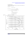
Additional Error
Additional errors are calculated as follows.
|Z| Measurement
Additional error for Impedance Ze [%] is calculated by substituting the values in the table
below into the following equation.
Ze [%] = ± {A + (Zs/Zx + Yo ×Zx) × 100}
where
A [%]
Test Fixture’s Proportional Error [%]
Yo [S]
Test Fixture’s Open Repeatability [S]
Zs [Ω]
Test Fixture’s Short Repeatability [Ω]
Zx [Ω]
Measured Impedance Value of DUT [Ω]
Zs
(30 + 150 × f ) × 10-3[Ω]
Yo
(2 + 30 × f ) × 10-6[S]
A
1.2 × f 2 [%]
where f is frequency (GHz).
D Measurement
Additional error for Dissipation Factor De is calculated by using the additional error for
Impedance Ze [%] as follows.
If Dx ≤ 0.1:
De = Ze / 100
If 0.1 < Dx ≤ 0.5:
De = (Ze / 100) × (1 + Dx)
where Dx is the measured value of D. It is necessary for Ze to be below 10 %.
NOTE
D is not expressed as a percentage but as an absolute value.
66
Chapter 5
Specifications and Supplemental Performance Characteristics
Supplemental Performance Characteristics
Rs (ESR) Measurement
Additional error Rse[%] of the Rs measurement is calculated by using the additional error
for Impedance Ze [%] as follows.
If Dx ≤ 0.1:
Rse [%] = Ze / Dx
If 0.1 < Dx ≤ 0.5:
2
Rse [%] = (Ze / Dx) × ( 1 + Dx )
Dx is the measured value of D and is calculated as follows.
Dx = 2 × π × f × Csx × Rsx,
where
f: measurement signal frequency
Csx: measured value of Cs
Rsx: measured value of Rs.
Figure 5-1
Additional Error for Impedance
Chapter 5
67
Specifications and Supplemental Performance Characteristics
Residual Inductance of the Shorting Bar
Residual Inductance of the Shorting Bar
The usual method to compensate the test fixture's residual inductance is to let SHORT =
0H. In this method, the measurement result is the relative value of the measured
impedance to the shorting bar's impedance. The short bar's residual inductance as a result
of its size and shape is not estimated.
On the other hand, there is a definition method to let SHORT = x H. In this method, the
measurement result is the absolute value of the device's impedance. The short bar's residual
inductance as a result of its size and shape is estimated under specific conditions and is
used as a reference value. This method, is useful for devices with values which are close to
the short conditions of the measurement system.
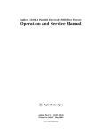
The reference inductance values presented Table 5-1 were simulated as the relative
difference to a disk-type 0 Ω termination on either the 7mm or the 3.5mm connector. The
measurement of these short bars under other conditions than shown below cannot
reproduce the reference inductance values.
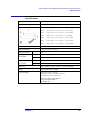
Table 5-1
Figure 5-2
Residual Inductance (Typical)
Shorting Bar Set
l [mm]
d [mm]
h [mm]
Offset [mm]
Connector
Inductance
(Typical)
0.6 × 0.3 × 0.3
0.6
0.3
0.3
0.0585
1 mm
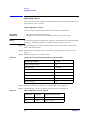
0.1 nH
1.0 × 0.5 × 0.5
1.0
0.5
0.5
0.75
3.5 mm
0.5 nH
1.6 × 0.8 × 0.8
1.6
0.8
0.8
0.45
3.5 mm
0.4 nH
2.0 × 1.2 × 0.8
2.0
1.2
0.8
1.5
7 mm
0.9 nH
3.2 × 1.6 × 0.8
3.2
1.6
0.8
0.9
7 mm
0.8 nH
Simulation Setup
68
Chapter 5
6
Service
This chapter describes the replaceable parts of the fixture, and the method for replacing
parts.
69
Service
Replaceable Parts
Replaceable Parts
Confirm the part number of each replaceable part with the exploded views and tables
shown below. Do not disassemble each unit into smaller components than shown in these
exploded views.
In placing an order for each replaceable part, designate the corresponding Agilent part
number and check digit (C/D). If a defective part to be replaced is part of a component that
cannot be disassembled, place an order for the entire component. Defective parts or
components may be sent to Agilent Technologies local sales/service office for repair.
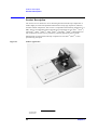
Pressure Unit
Figure 6-1
Exploded View of Pressure Unit Assembly
70
Chapter 6
Service
Replaceable Parts
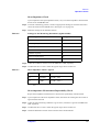
Table 6-1
Replaceable Parts (Pressure Unit)
No.
Agilent part
number
C/D
Qty
Description
1
3050-1138
7
1
Washer
2
16197-25002
9
1
Pressure rod
3
1480-1093
2
1
R-pin
4
16197-05001
6
1
Lever
5
N/A
8
1
Pressure unit
6
1460-2662
1
1
Spring
7
16197-23003
6
1
Shaft
8
16197-23004
7
1
Shaft
9
1460-2663
2
1
Spring
10
16197-24004
9
1
Pressure adjusting nut
11
16197-24005
0
1
Screw
12
0515-1185
7
1
Screw
13
16197-24003
8
2
Knob
14
N/A
7
1
Sliding block
15
0515-1550
2
Screw M3
Chapter 6
71
Service
Replaceable Parts
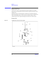
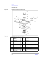
Electrode Unit
Figure 6-2
Exploded View of Electrode Unit Assembly
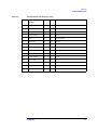
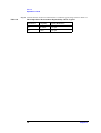
Table 6-2
Replaceable Parts (Electrode Unit)
No.
Agilent part
number
C/D
Qty
Description
1
0515-1077
6
2
Screw M-2.0
2
16197-25004
1
1
Guide holder
3
16197-25005
2
1
Device guide
4
16197-00603
4
1
Electrode plate
5
16197-25007
4
1
Device guide (for Option 001)
6
16197-00604
5
1
Electrode plate (for Option 001)
7
16197-25006
3
1
Device guide (blank)
8
16197-00601
2
1
Plate
72
Chapter 6
Service
Replaceable Parts
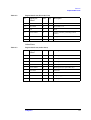
Table 6-2
Replaceable Parts (Electrode Unit)
No.
Agilent part
number
C/D
Qty
Description
9
0515-0914
8
4
Screw M3 × 0.5
10
0515-0952
4
4
Screw M2 × 0.4
11
N/A
3
1
Plate
12
16197-60001
2
1
Contact assembly (including contact
center)
13
16197-24001
6
1
Flange
14
1250-0907
8
1
Contact center
Other Parts
Table 6-3
Replaceable Parts (Other Parts)
No.
Agilent part
number
C/D
Qty
Description
1
16191-29005
4
1
Shorting bar 1.0 × 0.5
2
16191-29006
5
1
Shorting bar 1.6 × 0.8
3
16191-29007
6
1
Shorting bar 2.0 × 1.2
4
16191-29008
7
1
Shorting bar 3.2 × 1.6
5
16197-29001
6
1
Shorting bar (for Option Kit 001)
6
8710-2081
6
1
Tweezers
7
8710-0909
3
1
Allen wrench
8
16193-60002
9
1
Magnifying glass
9
16197-60050
1
1
Carrying case
Chapter 6
73
Service
Changing the Orientation of or Replacing the Contact Assembly
Changing the Orientation of or Replacing the Contact
Assembly
If the center electrode of the contact assembly is smeared, an unused clean area of the
center electrode can be used simply by changing the orientation of the contact assembly.
This section describes the method for changing the orientation of or replacing the contact
assembly.
To change the contact assembly orientation or replace the contact assembly, it is necessary
to use a 1.5-mm Allen wrench (Agilent part number: 8710-0909) and a Phillips
screwdriver.
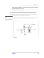
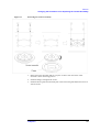
Procedure for Changing the Orientation of or Replacing the Contact
Assembly
1. Take off the guide holder, and remove the device guide and electrode plate. (See to
Figure 3-4 on page 36).
2. Remove the four screws from the upper side of the fixture, and then remove the contact
assembly and flange.
74
Chapter 6
Service
Changing the Orientation of or Replacing the Contact Assembly
Figure 6-3
Removing the Contact Assembly
3. Rotate the contact assembly and set it in place so that a clean area of the center
electrode is at the measuring position.
4. Install the flange, and tighten the screws.
5. Install the device guide and electrode plate. Then mount the guide holder and secure it
with the screws.
Chapter 6
75
Service
Operation Check
Operation Check
This section describes the operation check method. Be sure to perform the operation check
after each time a part is replaced.
Open Impedance Check
Conduct an Open impedance check with the fixture set for the OPEN state.
Necessary
equipment
•
•
NOTE
If a measuring instrument other than the 4291B is to be used, make the equivalent settings
according to the Operation and Service Manual for the instrument to be used.
Shorting bars (supplied as accessories)
Impedance measuring instrument (calibrated at the 7-mm connector end)
Step 1. Prepare a measuring instrument calibrated at the 7-mm connector end. Connect the test
fixture with this instrument.
Step 2. Set the fixture for the OPEN state, at the DUT measuring position (see Figure 3-18 on
page 47).
Step 3. Make the settings for the 4291B as follows.
Table 6-4
Settings for the Measuring Instrument (Agilent 4291B)
Measuring condition
Setting
Measurement parameter
Cp
Start frequency
100 MHz
Stop frequency
1 GHz
OSC Level
0.5 V
Number of points
2
Point averaging factor
16
Point averaging
ON
Step 4. Under these conditions, measure Cp at 100 MHz and 1 GHz, separately.
Step 5. Confirm that the Cp value is within the typical range shown in Table 6-5.
Table 6-5
OPEN Impedance Check: Typical
Parameter
Frequency
Typical (Absolute value)
Cp
100 MHz
700 fF ± 400 fF
Cp
1 GHz
700 fF ± 400 fF
76
Chapter 6
Service
Operation Check
Short Impedance Check
Upon completion of the open impedance check, carry out a short impedance check with the
fixture set for the SHORT state.
Step 6. At the DUT measuring position, connect an appropriate shorting bar with the electrode to
secure the fixture for the SHORT state. (See Figure 3-16 on page 45).
Step 7. Make the settings for the 4291B as follows.
Table 6-6
Settings for the Measuring Instrument (Agilent 4291B)
Measuring condition
Setting
Measurement parameter
Ls
Start frequency
100 MHz
Stop frequency
1 GHz
OSC Level
0.5 V
Number of points
2
Point averaging factor
16
Point averaging
ON
Step 8. Under this condition, measure Ls at 100 MHz and 1 GHz, separately.
Step 9. Confirm that the Ls value is within the typical range shown in Table 6-7.
Table 6-7
Short Impedance Check: Typical
Parameter
Frequency
Typical (Absolute value)
Ls
100 MHz
2.3 nH ± 1 nH *1
Ls
1 GHz
2.3 nH ± 1 nH *1
*1.The values given above are common to shorting bars of all
sizes.
Short-impedance Measurement Repeatability Check
Repeat short impedance measurement to check for the repeatability of measurement.
Step 1. Upon completion of the short impedance check, disconnect the shorting bar and connect it
again with the electrode.
Step 2. Under the same measuring conditions as given above, measure Ls again at 100 MHz and 1
GHz, separately.
Step 3. Confirm that the Ls value is within the typical range shown in Table 6-7.
Step 4. Obtain the difference between the first and second Ls measurements.
Chapter 6
77
Service
Operation Check
Step 5. Confirm that the variation in measurements is within the typical range shown in Table 6-8.
Table 6-8
Short-impedance Measurement Repeatability Check: Typical
Parameter
Frequency
Typical (Difference)
Ls
100 MHz
± 45 pH
Ls
1 GHz
± 20 pH
78
Chapter 6
A
Manual Changes
This appendix contains the information required to adapt this manual to versions or
configurations of the 16197A manufactured earlier than the current printing date of this
manual. The information in this manual applies directly to 16197A units with the serial
number that is printed on the title page of this manual.
79
Manual Changes
Manual Changes
Manual Changes
To adapt this manual to your 16197A, refer to Table A-1.
Table A-1
Manual Changes by Serial Number
Serial Prefix or Number
Make Manual Changes
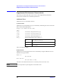
Agilent Technologies uses a two-part, ten-character serial number that is stamped on the
serial number plate (Figure A-1). The first five characters are the serial prefix and the last
five digits are the suffix.
Figure A-1
Serial Number Plate
80
Appendix A
Index
Numerics
1005
measuring position, 24
1608
measuring position, 24
2012
measuring position, 24
2520
example of preparing device guide, 41
example of preparing simple device guide, 42
3216
measuring position, 24
3225
measuring position, 24
A
accessories, 26
adapter, 18
Additional Error, 66
Allen wrench
names & functions, 26
package contents, 12
applicable chip (example), 33
assembly, 13
assembly check, 62
maintenance outline, 52
B
blank device guide
dimensional drawing, 39
names & functions, 26
package contents, 12
C
calibration
measurement flow, 30
carrying case
package contents, 12
center electrode
structure of electrode, 23
check sheet
example entry, 59
cleaning, 52, 54
areas requiring cleaning, 54
maintenance outline, 52
method, 54
cleaning rod, 54
connecting a DUT
mechanism, 23
structure of electrode, 24
contact assembly
changing the orientation or replacing, 74
D
deterioration check, 56
Index
acquiring reference values, 57
device
measuring position, 24
device guide
changing the orientation or replacing, 35
example of preparation, 40
mounting, 37
names & functions, 26
package contents, 12
removal, 36
simple device guide, 42
structure of electrode, 23
device holder
inside diameter, 40
device hole
dimensions, 34
Dimension, 65
DUT
connecting, 48
E
electrical length
setting, 32
electrode
structure, 23
positioning, 39
spacing, 34
structure, 23
electrode deterioration check, 57
check sheet, 60
example entry, 59
maintenence outline, 52
electrode plate
changing the orientation or replacing, 35
mounting, 37
names & functions, 26
package contents, 12
removal, 36
structure of electrode, 23
electrode unit
names & functions, 25
replaceable parts, 72
F
fixture compensation, 43
frame
selection, 33
structure of electrode, 23
Frequency
Specifications, 65
G
guide holder
names & functions, 25
guide holder fixing screws
changing positions, 16
81
Index
guide hole
data for preparation, 39
I
inspection before unpacking, 10
insulator assembly
mounting, 43
specification, 33
K
knob
names & functions, 25
L
latch
names & functions, 25
lever
names & functions, 25
M
magnifying glass
package contents, 12
installation, 14
names & functions, 27
Maintenance items, 52
manual changes, 79
Maximum Current, 65
Maximum Voltage, 65
measurement flow, 30
N
Nominal, 64
Non Operating Environment, 65
O
OPEN compensation, 47
open impedance check, 76
Open Repeatability, 66
Operating Environment, 65
operation and service manual
package contents, 12
operation check, 76
P
package contents, 11
pressure adjusting nut
adjusting method, 15
names & functions, 25
pressure rod
movable range, 40
names & functions, 25
standby position, 46
pressure unit
installation, 13
names & functions, 25
82
removal, 15
replaceable parts, 70
product appearance, 22
product description, 22
R
reference values
acquiring, 57
replaceable parts, 70
Electrode Unit, 72
Other Parts, 73
Pressure Unit, 71
replacement of parts
maintenance outline, 52
Rs
SHORT plate deterioration check, 58
S
Safety Standards, 65
Serial number plate, 80
service, 69
setting the measuring conditions
measurement flow, 30
SHORT compensation, 43
short impedance check, 77
Short Repeatability, 66
short-impedance measurement repeatability check, 77
shorting bar
connecting, 44
shorting bar set
names & functions, 26
package contents, 12
Simple device guide
example of preparation, 42
sliding block
names & functions, 25
Specifications, 65
storage, 15
electrode
structure, 23
Supplemental Performance Characteristics, 66
T
test fixture
attaching the adapter, 19
connecting with a measuring instrument, 18
tweezers
names & functions, 26
package contents, 12
Typical, 64
U
user limit values
example settings, 56
user maintenance, 51
Index
Index
W
Weight, 65
Index
83