1
Caution
Proper handling care should be taken when using the test fixture.
Refrain from applying brute force, doing so could damage the fixture.
Particularly the upper portion (where the DUT is mounted) of the
test fixture, where all the sensitive parts have been accurately set and
adjusted. Do not place the test fixture on top of a desk or any hard
objects with its face down (reverse).
Agilent 16044A Test Fixture
Operation and Service Manual
Seventh Edition
Agilent Part No. 16044-90040
May 2012
Printed in Malaysia
Notices
The information contained in this document is subject to change without notice.
This document contains proprietary information that is protected by copyright.All
rights are reserved. No part of this document may be photocopied, reproduced, or
translated to another language without the prior written consent of the Agilent
Technologies.
Agilent Technologies Japan, Ltd.
Component Test PGU-Kobe
1-3-2, Murotani, Nishi-Ku, Kobe-shi, Hyogo, 651-2241 Japan
© Copyright 1998, 1999, 2000, 2003, 2012 Agilent Technologies Japan, Ltd.
Manual Printing History
The manual’s printing date and part number indicate its current edition. The
printing date changes when a new edition is printed. (Minor corrections and
updates that are incorporated at reprint do not cause the date to change.) The
manual part number changes when extensive technical changes are incorporated.
December 1998
First Edition (part number: 16044-90000)
February 1999
Second Edition (part number: 16044-90010)
April 1999
Third Edition (part number: 16044-90020)
December 1999
Fourth Edition (part number: 16044-90020)
November 2000 Fifth Edition (part number: 16044-90030)
May 2003
Sixth Edition (part number: 16044-90040)
May 2012
Seventh Edition (part number: 16044-90040)
Safety Summary
The following general safety precautions must be observed during all phases of
operation, service, and repair of this instrument. Failure to comply with these
precautions or with specific WARNINGS elsewhere in this manual may impair the
protection provided by the equipment. In addition it violates safety standards of
design, manufacture, and intended use of the instrument.
2
The Agilent Technologies assumes no liability for the customer’s failure to comply
with these requirements.
•
DO NOT Operate In An Explosive Atmosphere
Do not operate the instrument in the presence of flammable gasses or fumes.
Operation of any electrical instrument in such an environment constitutes a
definite safety hazard.
•
Keep Away From Live Circuits
Operating personnel must not remove instrument covers. Component
replacement and internal adjustments must be made by qualified maintenance
personnel. Do not replace components with the power cable connected. Under
certain conditions, dangerous voltages may exist even with the power cable
removed. To avoid injuries, always disconnect power and discharge circuits
before touching them.
•
DO NOT Service Or Adjust Alone
Do not attempt internal service or adjustment unless another person, capable of
rendering first aid and resuscitation, is present.
•
DO NOT Substitute Parts Or Modify Instrument
Because of the danger of introducing additional hazards, do not install
substitute parts or perform unauthorized modifications to the instrument.
Return the instrument to a Agilent Technologies Sales and Service Office for
service and repair to ensure that safety features are maintained.
•
Dangerous Procedure Warnings
Warnings, such as the example below, precede potentially dangerous
procedures throughout this manual. Instructions contained in the warnings must
be followed.
WARNING
Dangerous voltages, capable of causing death, are presenting this instrument.
Use extreme caution when handling, testing, and adjusting this instrument.
Certification
Agilent Technologies certifies that this product met its published specifications at
the time of shipment from the factory. Agilent Technologies further certifies that
its calibration measurements are traceable to the United States National Institute of
Standards and Technology, to the extent allowed by the Institution’s calibration
facility, or to the calibration facilities of other International Standards Organization
members.
3
Warranty
This Agilent Technologies instrument product is warranted against defects in
material and workmanship for a period corresponding to the individual warranty
periods of its component products. Instruments are warranted for a period of one
year. Fixtures and adapters are warranted for a period of 90 days. During the
warranty period, Agilent Technologies will, at its option, either repair or replace
products that prove to be defective.
For warranty service or repair, this product must be returned to a service facility
designated by Agilent Technologies. Buyer shall prepay shipping charges to
Agilent Technologies and Agilent Technologies shall pay shipping charges to
return the product to Buyer. However, Buyer shall pay all shipping charges, duties,
and taxes for products returned to Agilent Technologies from another country.
Agilent Technologies warrants that its software and firmware designated by
Agilent Technologies for use with an instrument will execute its programming
instruction when property installed on that instrument. Agilent Technologies does
not warrant that the operation of the instrument, or software, or firmware will be
uninterrupted or error free.
Limitation Of Warranty
The foregoing warranty shall not apply to defects resulting from improper or
inadequate maintenance by Buyer, Buyer-supplied software or interfacing,
unauthorized modification or misuse, operation outside the environmental
specifications for the product, or improper site preparation or maintenance.
IMPORTANT
No other warranty is expressed or implied. Agilent Technologies specifically
disclaims the implied warranties of merchantability and fitness for a particular
purpose.
Exclusive Remedies
The remedies provided herein are buyer’s sole and exclusive remedies. Agilent
Technologies shall not be liable for any direct, indirect, special, incidental, or
consequential damages, whether based on contract, tort, or any other legal theory.
4
Assistance
Product maintenance agreements and other customer assistance agreements are
available for Agilent Technologies products.
For any assistance, contact your nearest Agilent Technologies Sales and Service
Office. Addresses are provided at the back of this manual.
Safety Symbol
General definitions of safety symbols used on the instrument or in manuals are
listed below.
Instruction Manual symbol: the product is marked with this symbol when it is
necessary for the user to refer to the instrument manual.
Alternating current.
Direct current.
On (Supply).
Off (Supply).
In position of push-button switch.
Out position of push-button switch.
Frame (or chassis) terminal. A connection to the frame (chassis) of the equipment
which normally include all exposed metal structure.
WARNING
This warning sign denotes a hazard. It calls attention to a procedure, practice,
condition or the like, which, if not correctly performed or adhered to, could
result in injury or death to personnel.
CAUTION
This Caution sign denotes a hazard. It calls attention to a procedure, practice,
condition or the like, which, if not correctly performed or adhered to, could result
in damage to or destruction of part or all of the product.
NOTE
Note denotes important information. It calls attention to a procedure, practice,
condition or the like, which is essential to highlight.
5
6
Contents
1. Overview
Product Overview . . . . . . . . . . . . . . . . . . . . . . . . . . . . . . . . . . . . . . . . . . . . . . . . . . . . . . . . . . . . . . . . . . . . . 10
Contents . . . . . . . . . . . . . . . . . . . . . . . . . . . . . . . . . . . . . . . . . . . . . . . . . . . . . . . . . . . . . . . . . . . . . . . . . . . . 11
Functions. . . . . . . . . . . . . . . . . . . . . . . . . . . . . . . . . . . . . . . . . . . . . . . . . . . . . . . . . . . . . . . . . . . . . . . . . . . . 12
2. Operation
Performing Open and Short Correction . . . . . . . . . . . . . . . . . . . . . . . . . . . . . . . . . . . . . . . . . . . . . . . . . . . . 16
Connecting the 16044A . . . . . . . . . . . . . . . . . . . . . . . . . . . . . . . . . . . . . . . . . . . . . . . . . . . . . . . . . . . . . . 16
Performing Short Correction. . . . . . . . . . . . . . . . . . . . . . . . . . . . . . . . . . . . . . . . . . . . . . . . . . . . . . . . . . . 17
Performing Open Correction. . . . . . . . . . . . . . . . . . . . . . . . . . . . . . . . . . . . . . . . . . . . . . . . . . . . . . . . . . . 18
DUT Measurement . . . . . . . . . . . . . . . . . . . . . . . . . . . . . . . . . . . . . . . . . . . . . . . . . . . . . . . . . . . . . . . . . . . . 19
Cleaning . . . . . . . . . . . . . . . . . . . . . . . . . . . . . . . . . . . . . . . . . . . . . . . . . . . . . . . . . . . . . . . . . . . . . . . . . . . . 21
Cleaning Points . . . . . . . . . . . . . . . . . . . . . . . . . . . . . . . . . . . . . . . . . . . . . . . . . . . . . . . . . . . . . . . . . . . . . 21
Cleaning Procedure . . . . . . . . . . . . . . . . . . . . . . . . . . . . . . . . . . . . . . . . . . . . . . . . . . . . . . . . . . . . . . . . . . 22
3.
Specifications and Supplemental Performance Characteristics
Specifications . . . . . . . . . . . . . . . . . . . . . . . . . . . . . . . . . . . . . . . . . . . . . . . . . . . . . . . . . . . . . . . . . . . . . . . . 24
Supplemental Performance Characteristics . . . . . . . . . . . . . . . . . . . . . . . . . . . . . . . . . . . . . . . . . . . . . . . . . 25
Additional Errors. . . . . . . . . . . . . . . . . . . . . . . . . . . . . . . . . . . . . . . . . . . . . . . . . . . . . . . . . . . . . . . . . . . . 25
D Measurement . . . . . . . . . . . . . . . . . . . . . . . . . . . . . . . . . . . . . . . . . . . . . . . . . . . . . . . . . . . . . . . . . . . . . 27
Rs (ESR) Measurement. . . . . . . . . . . . . . . . . . . . . . . . . . . . . . . . . . . . . . . . . . . . . . . . . . . . . . . . . . . . . . . 27
Spring pressure . . . . . . . . . . . . . . . . . . . . . . . . . . . . . . . . . . . . . . . . . . . . . . . . . . . . . . . . . . . . . . . . . . . . . 27
4. Service
Maintenance . . . . . . . . . . . . . . . . . . . . . . . . . . . . . . . . . . . . . . . . . . . . . . . . . . . . . . . . . . . . . . . . . . . . . . . . . 30
Replacable Parts for DUT Block Assembly . . . . . . . . . . . . . . . . . . . . . . . . . . . . . . . . . . . . . . . . . . . . . . . 31
Replacing the Measuring Block and Pin Adjustment . . . . . . . . . . . . . . . . . . . . . . . . . . . . . . . . . . . . . . . . . . 38
Preparing the Measuring Block . . . . . . . . . . . . . . . . . . . . . . . . . . . . . . . . . . . . . . . . . . . . . . . . . . . . . . . . 38
Removing the Measuring Block . . . . . . . . . . . . . . . . . . . . . . . . . . . . . . . . . . . . . . . . . . . . . . . . . . . . . . . . 41
Mounting the Measuring Block and Adjusting the Pin. . . . . . . . . . . . . . . . . . . . . . . . . . . . . . . . . . . . . . . 42
7
Contents
8
1. Overview
2. Chapter Title
3. Chapter Title
4. Chapter Title
Overview
1
5. Chapter Title
9
Overview
Product Overview
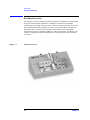
Product Overview
The 16044A is a four-terminal test fixture designed for impedance measurements.
Its precise measurement capabilities is adapted to evaluate low impedance
components such as high value capacitor. Contact resistance produces an error in
the D (dissipation factor) readings. In order to solve this problem, 16044A was
designed to have a Kelvin (four terminal) contact,which ensures repeatable
measurements for low impedance SMD L,C and R components. In addition , the
16044A is equipped with a mechanism that can easily perform Open and Short
correction.
Figure 1-1
Product Overview
10
Chapter 1
Contents
1. Overview
Overview
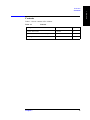
Contents
Table 1-1 shows contents of the 16044A.
Table 1-1
Contents
Part Number
Quantity
16044A Test Fixrure
16044A
1
Operation and Service Manual (English)
16044-90030
1
Cleaning Rod
5182-7586
1
2. Chapter Title
Description
3. Chapter Title
4. Chapter Title
5. Chapter Title
Chapter 1
11
Overview
Functions
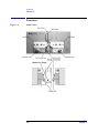
Functions
Figure 1-2
16044A Parts
12
Chapter 1
FUNCTION
Open Plate
Used for open correction measurement.
Short Plate
Used for open and short correction measurement.
Low Block
Connected to the LCUR , LPOT terminals.
High Block
Connected to the HCUR , HPOT terminals.
Low Block Knob
Use for lateral adjustments.
High Block Knob
Use for lateral adjustments, rotating the knob clockwise
2. Chapter Title
Parts
sets the block in a fix position.
Used for adjusting the stage height.
Rod Locking Knob
Used for locking the positioning rod in a fix position.
Blade Electrode
Connects the DUT electrode with the probe pin. The Blade
Electrode of each Low and High Blocks are connected to
the LPOT and HCUR respectively.
Probe Pin
Connects the DUT electrode with the blade electrode. The
Probe Pin of each Low and High Blocks are connected to
the LCUR and HPOT respectively.
Measuring Stage
Where the DUT is mounted.
3. Chapter Title
Positioning Rod
1. Overview
Overview
Functions
4. Chapter Title
5. Chapter Title
Chapter 1
13
Overview
Functions
14
Chapter 1
1. Chapter Title
2. Operation
3. Chapter Title
4. Chapter Title
2
Operation
5. Chapter Title
This chapter describes the proper methods for open and short correction and DUT
measurement.
15
Operation
Performing Open and Short Correction
Performing Open and Short Correction
To enhance measurement accuracy, open and short correction should be done before DUT
measurement. The following procedure shows correction and measurement by the 16044A.
CAUTION
Proper handling care should be taken when using the test fixture. Refrain from applying
brute force, doing so could damage the fixture.Particularly the upper portion (where the
DUT is mounted) of the test fixture, where all the sensitive parts have been accurately set
and adjusted. Do not place the test fixture on top of a desk or any hard objects with its face
down (reverse).
Connecting the 16044A
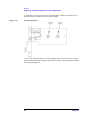
1. Set the cable length setting of the measuring instrument at 0 m.
2. Connect the 16044A directly to the UNKNOWN terminals as shown in Figure 2-1.
Figure 2-1
Connecting the 16044A
16
Chapter 2
Performing Short Correction
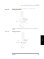
1. Refer to Figure 2-2(1), adjust the positioning rod to its minimum height by gently
pulling it backwards.
1. Chapter Title
Operation
Performing Open and Short Correction
2. Adjust the High Block to the right, giving space for the short plate before locking the
horizontal knob.
CAUTION
If the High Block can not be adjusted to the right, Do Not to pull down the short plate.
Doing so could damage the probe pin.
Pull down the short plate (Figure 2-2 (2)).
CAUTION
When operating the Low/High Block, take caution in applying force to the short
plate.Sudden impact could damage the blade electrode and probe pin.
2. Operation
3. Move the Low Block to the left, hold to a position before pulling down the short plate.
4. Connect the Low Block gently to the short plate.
5. Loosen the horizontal locking knob, connect the High Block slowly to the short plate.
CAUTION
During operation, with the High/Low Block connected to the short plate. Do Not attempt
to move the short plate, doing so could damage the probe pin.
Figure 2-2
Performing Short Correction
3. Chapter Title
6. Follow the directions in your manual when using the measuring instrument. Make sure
that you perform the short correction (Figure 2-2 (3)).
4. Chapter Title
5. Chapter Title
Chapter 2
17
Operation
Performing Open and Short Correction
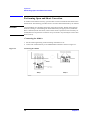
Performing Open Correction
1. Adjust the positioning rod to its minimum height by gently pulling it backwards.
2. Adjust the High Block to the right giving enough space for the short plate before
locking the horizontal knob.
3. Move the Low Block to the left, hold to a position before pulling down the open plate
(Figure 2-3(1)).
CAUTION
If the Low Block can not be adjusted to the left terminal, Do Not pull down the open plate.
Doing so could damage the probe pin.
4. Connect the Low Block slowly to the open plate.
CAUTION
When operating the Low/High Block, take caution in applying force to the open and short
plate. Sudden impact could damage the blade electrode and probe pin.
5. Slowly pull down the short plate (Figure 2-3(2)).
6. Loosen the horizontal locking knob, connect the High Block slowly to the short plate
(Figure 2-3(3)).
7. Follow the directions in your manual when using the measuring instrument.Make sure
that you perform the open correction.
CAUTION
Figure 2-3
During operation, when the High/Low Block is connected to the open/short plate. Do Not
attempt to move the open/short plate, doing so could damage the probe pin.
Performing Open Correction
18
Chapter 2
DUT Measurement
1. Chapter Title
Operation
DUT Measurement
Before performing DUT measurement, open and short corrections should be done as
described in the previous sections.
1. Adjust the High Block in order to position the DUT at the center of the measuring
stage, then tighten the high block knob (Figure 2-5(1)).
2. Adjust the Low Block to the left then hold to a position giving enough space before
placing the DUT on the measuring stage. Mount the DUT on the measuring stage.
2. Operation
3. Adjust the positioning rod with respect to the DUT’s size (Figure 2-5(2)).
Figure 2-4
Performing DUT Measurement
3. Chapter Title
4. Chapter Title
5. Chapter Title
Chapter 2
19
Operation
DUT Measurement
NOTE
Figure 2-5
Make sure that proper adjustments are made to ensure accurate mesurement.The DUT
should be properly connected with the probe pin and blade electrode at four points (refer to
Figure 2-5).Even if the DUT is too small use a magnifying lens to make sure that four
points are in proper contact.
Proper DUT Position
4. Tighten the rod locking knob.
5. Slowly connect the Low Block’s blade electrode to the DUT (Figure 2-5(3)).
6. Follow the directions of the operating manual in doing the measurement.
7. If you are going to measure another DUT of the same size, simply adjust the Low
Block to the left and change the DUT without moving the High Block.
NOTE
Contact pressure could cause measurement variations in the DUT, when measuring ferrite
inductor or multi-layer ceramic capacitors with high permittivity.
NOTE
In case the probe pin got damaged use the provided probe pin with part number 42110A
(probe pin × 4). Replacement procedure is listed on “Chapter 4 Service”.
20
Chapter 2
Cleaning
1. Chapter Title
Operation
Cleaning
To keep higher reliability and better measurements, regular cleaning of the following
points with the furnished cleaning rod (Agilent Part Number 5182-7586) is recommended.
Figure 2-6
Cleaning rod
2. Operation
Cleaning Points
Figure 2-7 shows required cleaning points.
Figure 2-7
Probe Pin (1 of Figure 2-7, contact points of the DUT)
Blade Electrode (2 of Figure 2-7, contact points of the DUT)
Short Plate (3 of Figure 2-7, contact points of the Probe Pin and Blade Electrode)
Spring (4 of Figure 2-7, contact point of the Low BLock)
3. Chapter Title
•
•
•
•
Cleaning Points
4. Chapter Title
5. Chapter Title
Chapter 2
21
Operation
Cleaning
Cleaning Procedure
Scrub the dirt on the points shown in Figure 2-7 with the rubber (white) side of the
cleaning rod. Particularly the probe pin, the plating of the DUT’s electrode could stick to
the probe pin. Take caution when cleaning the probe pin with the cleaning rod. The probe
pin is very sensitive and could be damaged easily.
NOTE
Replace the probe pin if the dirt can not be removed. And use the provided probe pin with
part number 42110A (probe pin × 4). Replacement procedure is listed on “Chapter 4
Service”.
22
Chapter 2
1. Chapter Title
2. Chapter Title
3. Specifications and
Supplemental Performance
Characteristics
4. Chapter Title
3
Specifications and Supplemental
Performance Characteristics
5. Chapter Title
This chapter provides the specifications and supplemental performance
characteristics of the 16044A test fixture.
23
Specifications and Supplemental Performance Characteristics
Specifications
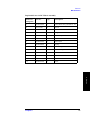
Specifications
Applicable Instruments
LCR meters and Impedance Analyzers with
four-terminals
Applicable DUT Type
SMD(surface mount device) or chip components
Applicable DUT Size
Frequency
≤ 10MHz
DC Bias
± 40V Maximum
Operating
Environment
temp.
0°C to +55°C
humidity
15% to 95%RH( @ wet bulb temp. <40°C)
Non Operating
temp.
-40°C to +70°C
Environment.
humidity
≤ 90 % RH ( @ wet bulb temp. <65°C)
Dimension
160 (W) × 70 (H) × 98 (D) mm
Weight
550g
NOTE
In using the stage, the electrode of the
DUT must be in contact at an angle (R)
less than or equal to 0.4mm.If not the
probe pin may not be able to measure
the DUT properly.
24
Chapter 3
Supplemental Performance Characteristics
1. Chapter Title
Specifications and Supplemental Performance Characteristics
Supplemental Performance Characteristics
This section provides useful data on the 16044A. These supplemental performance
characteristics should not be considered specifications.
Additional Errors
2. Chapter Title
Additional errors are calculated as follows.
|Z| Measurement
Additional error Ze [%] of the |Z| measurement is calculated by substituting the
values in the table below into the following equation.
Ze [%] = ± {A + (Zs/Zx + Yo ×Zx) × 100}
where
Additional Error ( Proportional Error)
Zs [Ω]
Short Repeatability (Impedance)
Yo [S]
Open Repeatability (Admittance)
Zx [Ω]
Measured Value (Impedance)
3. Specifications and
Supplemental Performance
Characteristics
A [%]
Without extension cable
Applicable Instruments : 4192A, 4194A, 4263B, 4268A, 4278A, 4279A,
4284A, 4285A, 4294A, 4338B
{1.5 + 40 × ( f / 10 ) } × 10-3 [Ω]
Yo
{1.5 + 200 × ( f / 10 )} × 10-9 [S]
A
2 × ( f / 10 )2 [%]
4. Chapter Title
Zs
where f is the measurement frequency (MHz).
4194A (extension cable 1m)
Zs
{3 + 80 × ( f / 10 MHz)} × 10-3 [Ω]
Yo
{3 + 400 × ( f / 10 )} × 10-9 [S]
A
5 × ( f / 10 )2 [%]
Chapter 3
5. Chapter Title
where f is the measurement frequency (MHz).
25
Specifications and Supplemental Performance Characteristics
Supplemental Performance Characteristics
4285A, 4294A (extension cable 1m)
Zs
{3 + 80 × ( f / 10 )} × 10-3 [Ω]
Yo
{3 + 400 × ( f / 10 )} × 10-9 [nS]
A
f ≤ 5 MHz
5 × ( f / 10 )2 [%]
5 MHz < f ≤ 10 MHz
6 × ( f / 10 ) [%]
where f is the measurement frequency (MHz).
4285A, 4294A (extension cable 2m)
Zs
{3 + 80 × ( f / 10 )} × 10-3 [W]
Yo
{3 + 400 × ( f / 10 )} × 10-9 [nS]
A
f ≤ 5 MHz
7 × ( f / 10 )2 [%]
5 MHz < f ≤ 10 MHz
6 × ( f / 10 ) [%]
where f is the measurement frequency (MHz).
Figure 3-1
Additional Error of the |Z| measurement
26
Chapter 3
D Measurement
Additional error De of the D measurement is calculated by additional error Ze [%]
of |Z| measurement as follows.
1. Chapter Title
Specifications and Supplemental Performance Characteristics
Supplemental Performance Characteristics
If Dx ≤ 0.1:
De = Ze / 100
If 0.1 < Dx ≤ 0.5
2. Chapter Title
De = ( Ze / 100) × (1 + Dx)
where Dx is the measured value of D. It is necessary for Ze to be below 10 %.
NOTE
D is not expressed as a percentage but as an absolute value.
Rs (ESR) Measurement
Additional error Rse[%] of the Rs measurement is calculated by additional error
Ze [%] of |Z| measurement as follows.
3. Specifications and
Supplemental Performance
Characteristics
If Dx ≤ 0.1:
Rse [%] = Ze / Dx
If 0.1 < Dx ≤ 0.5
Rse [%] = ( Ze / Dx) × ( 1 + Dx2 )
Dx is the measured value of D and is calculated as follows.
Dx = 2 × π × f × Csx × Rsx
where
f: measurement signal frequency
4. Chapter Title
Csx: measured value of Cs
Rsx: measured value of Rs,
Spring pressure
Spring Pressure
140 g ± 30 [g] (applicable short measurement)
5. Chapter Title
Chapter 3
27
Specifications and Supplemental Performance Characteristics
Supplemental Performance Characteristics
28
Chapter 3
1. Chapter Title
2. Chapter Title
3. Chapter Title
4. Service
4
Service
5. Chapter Title
This chapter provides information on servicing and proper maintenance.
29
Service
Maintenance
Maintenance
Check the parts number of all replacable parts as provided in the tables and figures
listed below. Do not attempt to disassemble any parts that is not included in the
figure.
The tables and figures below show and list the replacable parts for the 16044A.
The parts listed can be ordered from your nearest Agilent Technologies Sales and
Service Office. Ordering information must include the Agilent part number and the
quantity required.
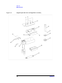
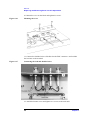
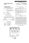
Figure 4-1
Replacable Parts for DUT Block Assembly
30
Chapter 4
Replacable Parts for DUT Block Assembly
Qty.
Descrpition
1
16044-65003
1
DUT Block Assy (includes 6~15)
2
0515-1550
2
Screw
3
0515-0924
4
Screw
4
16044-00605
1
Angle
5
16044-61604
1
Wire Assy
6
16044-65004
1
Plate:Short
7
16044-26501
1
Plate:Open
9
16044-08003
1
Spring
10
16044-25002
1
Positioning Rod
11
16044-24012
1
Rod Locking Knob
12
16044-24005
1
Shaft
13
16044-00604
1
Contact
14
0515-1872
1
Screw
15
16044-61603
1
Wire
3. Chapter Title
Part No.
2. Chapter Title
Reference
Designator
1. Chapter Title
Service
Maintenance
4. Service
5. Chapter Title
Chapter 4
31
Service
Maintenance
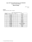
Figure 4-2
(Right) Replacable Parts for High Block Assembly
32
Chapter 4
Replacable Parts for High Block Assembly
Qty.
Description
1
0515-0952
2
Screw
2
0515-0924
2
Screw
3
16044-04003
1
Top Cover
4
16044-04005
1
L - Cover
5
0515-0952
2
Screw
6
16044-24004
1
Knob
7
1480-0815
1
Spring Pin
8
3050-1983
1
Washer
9
16044-24010
1
Nut
10
1494-0078
1
Slide Unit
11
1460-2409
1
Spring
12
16004-65006
1
Right Meas Block (includes 13)
13
1253-0549
1
Probe Pin
14
16044-08001
1
Spring
15
0515-2421
2
Screw
16
16044-24007
1
Nut
3. Chapter Title
Part No.
2. Chapter Title
Reference
Designator
1. Chapter Title
Service
Maintenance
4. Service
5. Chapter Title
Chapter 4
33
Service
Maintenance
Figure 4-3
(Left) Replacable Parts for Low Block Assembly
34
Chapter 4
Replacable Parts for Low Block Assembly
Qty.
Description
1
16044-24011
1
Standoff
2
0515-0924
2
Screw
3
0515-0952
2
Screw
4
16044-04004
1
Upper Cover
5
16044-04006
1
L - Cover
6
16044-65007
1
Meas Block Left (includes 7)
7
1253-0549
1
Probe Pin
8
1494-0078
1
Slide Unit
9
16044-24007
1
Nut
10
3050-1984
1
Washer
11
0515-0952
2
Screw
3. Chapter Title
Parts No.
2. Chapter Title
Reference
Designator
1. Chapter Title
Service
Maintenance
4. Service
5. Chapter Title
Chapter 4
35
Service
Maintenance
Figure 4-4
Replacable Parts for Cover Assembly
36
Chapter 4
Replacable Parts for Cover Assembly
Qty.
Description
1
16044-04001
1
Top Cover
2
N/A
4
Nut (included in BNC connector)
3
3050-0067
4
Washer
4
3050-0789
3
Washer : PTFE
5
16047-40002
4
Washer : Insulator
6
16044-60002
2
BNC Connector (with lever)
7
1253-0476
2
BNC Connector (w/o lever)
8
6960-0016
2
Plug Hole
9
0515-0914
6
Screw
10
16044-04002
1
Bottom Cover
3. Chapter Title
Parts No.
2. Chapter Title
Reference
Designator
1. Chapter Title
Service
Maintenance
4. Service
5. Chapter Title
Chapter 4
37
Service
Replacing the Measuring Block and Pin Adjustment
Replacing the Measuring Block and Pin Adjustment
This section describes the procedures in replacing the measuring block.
Replacing the measuring block consists the following procedures: preparing the
measuring block (new), removing the measuring block (old) and mounting the
(new) measuring block and adjusting its pin. If you are going to replace the probe
pin only the above procedures need not be followed.
Follow the procedures listed below when replacing the high block.The same
procedure follows for the low block.
You need to use a pin adjuster (Agilent P/N 16044-65005) when adjusting the
position of the probe pin. Also, it is recommended that you use a pin set,
magnifying lens and the like in doing this adjustment.
Preparing the Measuring Block
Insert the pin adjuster to the new measuring block.
1.Have the replacable parts prepared.
NOTE
The blade electrode of the new block has already been pre-adjusted. Do not loosen
the screw that holds the blade electrode. Refrain from applying brute force.
Figure 4-5
Measuring block replacement (new High block)
38
Chapter 4
2.Remove the probe pin from the measuring block with a pin set or tools alike.
Removing the probe pin
NOTE
Do not bend or misplace the probe pin since it will be used later on.
2. Chapter Title
Figure 4-6
1. Chapter Title
Service
Replacing the Measuring Block and Pin Adjustment
3. Chapter Title
3. Insert the thin side pin of the adjuster while observing its edge.
Figure 4-7
Inserting the pin adjuster
4. Service
5. Chapter Title
Chapter 4
39
Service
Replacing the Measuring Block and Pin Adjustment
4.Be sure there are no gaps between the pin adjuster and blade electrode.
Figure 4-8
Checking the position of the pin adjuster
40
Chapter 4
Removing the Measuring Block
Remove the old block from the main unit (test fixture ).
1. Chapter Title
Service
Replacing the Measuring Block and Pin Adjustment
1. Loosen the 6 screws from the main unit to remove the bottom cover.
2. Disconnect the shielded wires that connects the block from the BNC connector.
Also, disconnect the lead wire from the block terminal.
3. Remove the screws holding the cover and measuring block.
2. Chapter Title
Figure 4-9
Removing the old block
3. Chapter Title
4. Service
5. Chapter Title
Chapter 4
41
Service
Replacing the Measuring Block and Pin Adjustment
Mounting the Measuring Block and Adjusting the Pin
Mount the measuring block to the main unit with the pin adjuster attached and
adjust the position of the pin.
1. Loosen the rod locking knob.
2. As shown in figure 4-10 adjust the height of the positioning rod until it reaches
the position stopper.
Figure 4-10
Adjusting the height of the positioning rod
3. Tighten the rod locking knob.
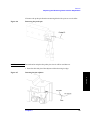
4 As shown in figure 4-11 attach the measuring block to the unit, half-tight the 2
screws in order to adjust its position.
42
Chapter 4
Figure 4-11
Half-tight the measuring block
1. Chapter Title
Service
Replacing the Measuring Block and Pin Adjustment
2. Chapter Title
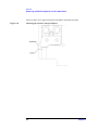
Figure 4-12
3. Chapter Title
5. Adjust the position of the measuring block, such that there are no contact gaps
between the pin adjuster and positioning rod.
Adjusting the position of the block
4. Service
5. Chapter Title
Chapter 4
43
Service
Replacing the Measuring Block and Pin Adjustment
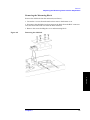
6. Tighten the 2 screws to secure the measuring block. Make sure the block is in
proper position such that there are no position gaps.
Figure 4-13
Screwing the block
7. Move the measuring block to its left and right sides. Check if there are no gaps
between the positioning rod and the pin adjuster. The pin adjuster should not bump
into the positioning rod.
44
Chapter 4
8. Move the measuring block to the right, then remove the pin adjuster.
Figure 4-14
1. Chapter Title
Service
Replacing the Measuring Block and Pin Adjustment
Removing the pin adjuster
2. Chapter Title
3. Chapter Title
9. Move the measuring block to the right, then insert the probe pin previously
removed.
Figure 4-15
Inserting the probe pin
4. Service
5. Chapter Title
Chapter 4
45
Service
Replacing the Measuring Block and Pin Adjustment
10. Mount the cover on the block and tighten its screws.
Figure 4-16
Mounting the cover
11. Connect the shielded wires of the block to the BNC connector. And resolder
the lead wire to the terminal.
Figure 4-17
Connecting the lead and shielded wires
12. Attach the bottom cover and tighten its 6 screws to the main unit.
46
Chapter 4
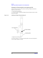
Checking the pin position
The following guidlines are provided in determining the correct position of the
probe pin.
The probe pin should be leading the blade electrode by approximately 0.3mm.
•
The spacing between the probe pin and blade electrode should be
approximately 0.1 mm.
•
The spacing between the probe pin and positioning rod should be
approximately 0.1 mm.
•
The probe pin should not be in contact with the positioning rod, even if the
block is moved laterally.
2. Chapter Title
Figure 4-18
•
1. Chapter Title
Service
Replacing the Measuring Block and Pin Adjustment
Magnifying the position of the probe pin
3. Chapter Title
4. Service
5. Chapter Title
Chapter 4
47
Service
Replacing the Measuring Block and Pin Adjustment
48
Chapter 4