1
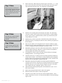
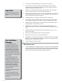
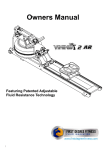
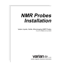
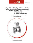
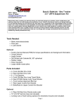
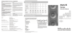
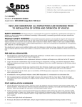
#J2100, J2202 Installation Instructions
3/4", 1-3/4” Coil Spacer Kit
1997-2006 Jeep TJ Front/Rear
1993-1998 Jeep ZJ Front/Rear
1984-2001 Jeep XJ Front Only
Read and understand all instructions and warnings prior to installation of product
and operation of vehicle.
Zone Offroad Products recommends this system be installed by a professional technician. In addition to these instructions, professional knowledge of disassembly/ reassembly procedures and post installation checks must be known. Minimum tool requirements include
the following: Assorted metric and standard wrenches, hammer, hydraulic floor jack and a set of jack stands. See the "Special Tools
Required" section for additional tools needed to complete this installation properly and safely.
»»P
roduct
Safety Warning
Certain Zone Offroad Products are intended to improve off-road performance. Modifying your vehicle for off-road use may result in
the vehicle handling differently than a factory equipped vehicle. Extreme care must be used to prevent loss of control or vehicle rollover. Failure to drive your modified vehicle safely may result in serious injury or death. Zone Offroad Products does not recommend
the combined use of suspension lifts, body lifts, or other lifting devices.
You should never operate your modified vehicle under the influence of alcohol or drugs. Always drive your modified vehicle at reduced speeds to ensure your ability to control your vehicle under all driving conditions. Always wear your seat belt.
»»T
echnical
Support
Live Chat provides instant communication with Zone tech support. Anyone can access live
chat through a link on www.zoneoffroad.com .
www.zoneoffroad.com may have additional information about this product including the latest instructions, videos, photos, etc.
Send an e-mail to [email protected] detailing your issue for a quick response.
888.998.ZONE Call to speak directly with Zone tech support.
»»P
re-Installation
Difficulty Level
easy 1
2
3 4 5 difficult
Estimated installation hours: 1-3
Special Tools Required
Small Pickle Fork - TJ Only
Tire/Wheel Fitment
For 1-3/4" Lift
Notes
1.Special literature required: OE Service Manual for model/year of vehicle. Refer to
manual for proper disassembly/reassembly procedures of OE and related components.
2.Adhere to recommendations when replacement fasteners, retainers and keepers are called
out in the OE manual.
TJ: 32” x 11.50” tire/15x8, 3.5”
B.S. wheel
XJ, ZJ: 30" x 9.50" Tire/15x8,
stock offset wheel
3.Larger rim and tire combinations may increase leverage on suspension, steering, and
related components. When selecting combinations larger than OE, consider the additional stress you could be inducing on the OE
and related components.
4.Post suspension system vehicles may experience drive line vibrations. Angles may require tuning, slider on shaft may require replacement, shafts may need to be lengthened or trued, and U-joints may need to be replaced.
5.Secure and properly block vehicle prior to installation of Zone Offroad Products components. Always wear safety glasses when using power tools.
6.If installation is to be performed without a hoist, Zone Offroad Products recommends rear alterations first.
7.Due to payload options and initial ride height variances, the amount of lift is a base figure. Final ride height dimensions may vary in
accordance to original vehicle attitude. Always measure the attitude prior to beginning installation.
rev060313
»»Zone Offroad Products • 491 W. Garfield Ave., Coldwater, MI 49036 • 888.998.ZONE • www.zoneoffroad.
com
INSTALLATION INSTRUCTIONS
1.
Park the vehicle on an appropriate work surface. Ensure that the vehicle is in
park for automatic transmission or in first gear for manual transmissions and the
parking brake is applied. Block the wheels for added safety.
2.
These installation instructions outline the installation for the J2100/J2202 coil
spring spacer kit for the front and rear of a Jeep TJ and ZJ as well as the front of
the Jeep XJ. (2) J2100/J2202 kits will be required to complete the installation
on the front and rear of the TJ and ZJ vehicles.
3.
The following steps outline the installation of the J2100/J2202 kit without the
use of any type of coil compressor device. Using a coil compressor will allow
some of the disassembly steps to be skipped but Zone Offroad does not recommend using a coil compressor during this installation.
»»F
ront Installation
1.
(TJ, ZJ and XJ Models)
Remove the bolt mounting the front track bar to the passenger’s side of the axle
Figure 1. Save track bar bolt and nut tab. Allow the track bar to hang free.
Step 1 Note
The track bar bolt may require a
T‑50 Torx socket on early models.
Figure 1
2.
Raise the front of vehicle with a hydraulic jack and place jack stands under the
frame rails, just behind the lower control arm pockets.
3.
Remove the wheels.
4.
All ZJ and 1997 models TJ only: Mark the position of the alignment cam adjusters located at the end of each front lower control arm at the axle Figure 2.
Figure 2
J2200 Installation - pg. 2
5.
6.
Support the front axle with a hydraulic jack. Disconnect the shocks from the
axle. Save the lower shock hardware.
Remove the upper mounting nut from the sway bar links Figure 3. For XJ/ZJ
models remove and save the upper nut and stem hardware. For TJs, disconnect
the links from the sway bar with a pickle fork to release the tapered seat. Save
nut.
Step 5 Note
If replacing the shocks, remove
the shocks from the upper mount
as well and remove from vehicle.
The upper mounting hardware will
not be reused.
Figure 3
7.
Remove the cotter pin and castellated nut from the drag link end at the pitman
arm Figure 4. Thread the nut back on a couple of turns. Strike the pitman arm
near the drag link end to release the tapered seat. Take care not to damage the
end. Remove the nut and the drag link from the pitman arm. Save hardware.
Figure 4
8.
Remove the driver’s side coil spring retainer clip located on the back side of the
axle coil seat. Save clip and bolt.
9.
Loosen the driver’s and passenger’s side lower control arm bolts at the axle.
Completely remove the passenger’s side bolt and leave the driver’s side in
place. This should allow the axle to lower enough to remove and install the coil
springs.
10.
Lower the axle with the hydraulic jack and remove the coil springs. Take care
not to over extend the brake lines.
Step 8 Note
Some models may have a passenger's side retaining clip as well. If
that is the case remove it also.
J2200 Installation - pg. 3
11.
Step 11 Note
Remove the factory rubber bump stop from the upper coil mount Figure 5. Large
pliers can be used to pull it out. Remove the factory bump stop retainer cup by
removing the bolt from the center. Save bumpstop, cup and hardware.
Bump stop removal is not necessary on models equipped with small
diameter bump stops (newer XJs).
On these models the coil spacer ID
is large enough to slide over the
bump stop.
Figure 5
Step 12 Note
The small “lip” on the coil spacer
should point down when it is
installed.
Step 13 Note
A small amount of grease on the
bump stop will make installation
easier.
J2200 Installation - pg. 4
12.
Slide the new coil spring spacer onto the upper coil mount. Leave the factory
coil spacer in place, the new mount will be positioned below it. While holding
the new spacer in place, reinstall the factory retainer cup with the factory bolt.
Torque hardware to 25 ft-lbs.
13.
With the factory retainer cup in place, reinstall the factory rubber bump stop.
14.
Reinstall the factory coil springs and rotate the ends so that they seat properly in
the axle mounts.
15.
Raise the axle until the coils seat against the new coil spacers and have a slight
amount of pressure on them. Reinstall the driver’s side coil retainer and torque to
20 ft-lbs. If equipped, install the passenger's side retainer as well.
16.
Reattach the passenger’s side lower control arm bolt/nut/washers. Snug the bolt
but do not tighten completely. Both lower control arm bolts will be tightened
with the weight of the vehicle on the suspension.
17.
If installation new shocks, attach to the upper mount with the provided upper
bushings/hardware. Leave the upper nut loose.
18.
Attach the shock (new or existing) to the axle with the original shock hardware.
Torque bolts to 20 ft-lbs. If new shocks are being installed, go back and tighten
the upper shock stem nut until the stem bushings begin to swell. Install the thin
jam nut on the stem and tighten it against the first nut.
19.
Reattach the drag link to the pitman arm with the original castellated nut.
Torque the nut to 60 ft-lbs. Align the cotter pin hole with the slots in the nut and
install the cotter pin. Never loosen the nut to align the cotter pin, only tighten.
If the original cotter pin is damaged, replace it with a new one.
20.
Install the wheels and torque the lug nuts to the manufacturer’s specs. See vehicle owner’s manual.
21.
Remove the jack stands and lower the vehicle to the ground.
22.
Bounce the front of the vehicle to settle the suspension.
23.
Attach the sway bar links to the sway bar with the original hardware. On TJ
models, torque nuts to 25 ft-lbs. For XJ/ZJ models tighten nut until the bushings
begin to swell.
24.
Reconnect the front track bar to the axle mount with the original hardware.
Torque bolt to 50 ft-lbs.
Step 24 Note
25.
Torque the lower control arm bolts to 85 ft-lbs.
26.
Check all hardware for proper torque.
To aid in aligning the track bar
hole have an assistant turn the
steering wheel to shift the trackbar
in the correct direction.
»»R
ear Installation
1.
(TJ and ZJ Models)
Disconnect the rear track bar from the passenger’s side frame mount Figure 6.
Save hardware.
Step 25 Note
If working on a ZJ or 97 model TJ,
be sure to align the marks made at
the beginning of the installation
before tightening the bolts.
Figure 6
2.
Raise the rear of vehicle with a hydraulic jack and place jack stands under the
frame rails, just ahead of the lower control arm pockets.
3.
Remove the wheels.
4.
Support the rear axle with a hydraulic jack. Disconnect the shocks from the
axle. If replacing the shocks, disconnect them from the frame mount also and
remove them from the vehicle. Save all shock hardware.
5.
Disconnect the sway bar links from the sway bar Figure 7. Save hardware.
Step 5 Note
TJ sway bar links are shown in the
figure. ZJs use a stem style link.
Remove the nut, washer and bushing to disconnect the sway bar.
Save all hardware.
Figure 7
J2200 Installation - pg. 5
6.
Lower the axle with the hydraulic jack and remove the coil springs.
7.
TJ Only: Remove the factory rubber bump stop from the upper coil mount.
Large pliers can be used to pull it out. Remove the factory bump stop retainer
cup by removing the bolt from the center.
Step 9 Note
8.
Slide the new coil spring spacer onto the upper coil mount. Leave the factory
coil spacer in place, the new mount will be positioned below it.
A small amount of grease on the
bump stop will make installation
easier.
9.
TJ Only: While holding the new spacer in place, reinstall the factory retainer cup
with the factory bolt. Torque bolt to 25 ft-lbs. With the factory retainer cup in
place, reinstall the factory rubber bump stop.
10.
Reinstall the factory coil springs in the upper and lower spring seats.
11.
If installing new shocks, attach the shocks to the frame with the original hardware. Torque TJ mount bolts to 20 ft-lbs. Torque ZJ mount bolts to 50 ft-lbs.
12.
Raise the rear axle until the shocks can be fastened to the axle mounts with the
original hardware. Torque bolts to 55 ft-lbs.
13.
Reattach the sway bar links to the sway bar with the original hardware. TJ
models, torque bolts to 30 ft-lbs. ZJ models, tighten nut until bushings begin to
swell.
14.
Install the wheels and torque the lug nuts to the manufacturer’s specs. See vehicle owner’s manual.
15.
Remove the jack stands and lower the vehicle to the ground.
16.
Bounce the rear of the vehicle to settle the suspension.
17.
Reattach the rear track bar to the passenger’s side frame mount with the original
hardware. Have an assistant push on the side of the body to help align the track
bar in the bracket. Torque bolt to 70 ft-lbs.
18.
Check all hardware for proper torque.
Post-Installation
Warnings
1. Check all fasteners for
proper torque. Check to ensure
for adequate clearance between
all rotating, mobile, fixed, and
heated members. Verify clearance
between exhaust and brake lines,
fuel lines, fuel tank, floor boards
and wiring harness. Check steering
gear for clearance. Test and inspect
brake system.
2. Perform steering sweep to
ensure front brake hoses have
adequate slack and do not contact
any rotating, mobile or heated
members. Inspect rear brake hoses
at full extension for adequate
slack. Failure to perform hose
check/ replacement may result in
component failure.
3. Perform head light check and
adjustment.
4. Re-torque all fasteners after
500 miles. Always inspect fasteners and components during routine
servicing.
J2200 Installation - pg. 6
»»P
ost-Installation
1.
A front end alignment is required to adjust toe-in setting as well as straighten the
steering wheel. Caster can be adjusted on all ZJ models and 97 model TJs using
the factory alignment cams bolts. Zone Suspension offers replacement cam bolt
kits for all 97-06 model TJs and 93-98 model ZJs, part #J5311.