1
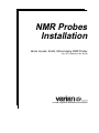
NMR Probes
Installation
Varian Liquids, Solids, Microimaging NMR Probes
Pub. No. 01-999034-00, Rev. B0798
nuclear magnetic resonance instruments
NMR Probes Installation
Varian Liquids, Solids, Microimaging NMR Probes
Pub. No. 01-999034-00, Rev. B0798
Applicability of manual:
Probes used with UNITYINOVA,MERCURY VxWorks-Powered (shortened to
MERCURY-VX throughout this manual), MERCURY, UNITYplus, GEMINI
2000, UNITY, VXR, and Gemini NMR spectrometer systems
Revision history:
As 87-195210-00 –
E0395 – Added Gen V probes
F0297 – Added 8-mm PFG Triple, 500 and 600
F0597 – Added AutoSwitchable and new Nano probes
G0997 – Added qtune improvements and VNMR 6.1 changes
H0298 – Updated for MERCURY-VX
As 01-999034-00 –
A0398 – Changed Pub. No., was 87-195210-00
B0798 – Updated AutoSwitchable section (ECO 8261) and MERCURY-VX qtune
Technical contributors: Robert Rice, Bao Nguyen, Layne Howard, Ali Behbin,
Laima Baltusis, Frits Vosman, Ron Haner, Jim Finnigan, Knut Mehr
Technical writer: Dan Steele
Technical editor: James Welch
Copyright ©1998 by Varian Associates, Inc.
All rights reserved. Printed in the United States.
The information in this document has been carefully checked and is believed to
be entirely reliable. However, no responsibility is assumed for inaccuracies.
Statements in this document are not intended to create any warranty, expressed
or implied. Specifications and performance characteristics of the software
described in this manual may be changed at any time without notice. Varian
reserves the right to make changes in any products herein to improve reliability,
function, or design. Varian does not assume any liability arising out of the
application or use of any product or circuit described herein; neither does it
convey any license under its patent rights nor the rights of others. Inclusion in this
document does not imply that any particular feature is standard on the
instrument.
MERCURY, UNITYINOVA, GEMINI 2000, UNITYplus VXR, UNITY, Gemini are
registered trademarks or trademarks of Varian Associates, Inc.
Oxford is a registered trademark of Oxford Instruments, Ltd.
Doty is a registered trademark of Doty Scientific, Inc.
Table of Contents
SAFETY PRECAUTIONS .................................................................................. 11
Chapter 1. Probe-Related Hardware .............................................................. 15
1.1
1.2
1.3
1.4
Overview of NMR Probe Hardware ....................................................................
Installing the Pneumatic System .........................................................................
Installing the Probe and Upper Barrel .................................................................
Pneumatics/Tachometer Box ...............................................................................
RT CP/MAS Pneumatics/Tachometer Box ..................................................
VT CP/MAS Pneumatics/Tachometer Box .................................................
Installing the Pneumatics/Tachometer Box .................................................
Replacing the Air/Gas Filter ........................................................................
15
17
18
20
20
20
21
22
Chapter 2. Adjustments and Tuning .............................................................. 23
2.1 Adjusting Spinning and Air Pressure ..................................................................
To Adjust the Cooling Air ...........................................................................
To Adjust the Bearing Air ............................................................................
To Adjust System Air Pressure ....................................................................
2.2 Using the qtune Graphical Probe Tuning Program .............................................
Tuning a Probe with qtune ...........................................................................
Adjusting the Center Frequency ..................................................................
Adjusting the Span .......................................................................................
Using Cursors, Grid, and Markers ...............................................................
Changing the Vertical Scale .........................................................................
Calculating the Q Value ...............................................................................
Calibrating the Tune System ........................................................................
Restoring Previous Calibration Files ...........................................................
Restoring Original Calibration Files ............................................................
Obtaining Online Help .................................................................................
2.3 Tuning Probes with UNITYINOVA or UNITYplus ..................................................
Using the TUNE INTERFFACE .................................................................
2.4 Tuning Probes with MERCURY-Series or GEMINI 2000 Systems .....................
Tuning the High-Band Observe and Decouple Channel ..............................
Tuning the Low-Band Observe Channel .....................................................
Tuning the 2H Lock Channel .......................................................................
2.5 Tuning Probes with UNITY or VXR ..................................................................
Tuning High-Band Observe and Decouple Channels ..................................
Tuning Low-Band Observe and Decouple Channels ...................................
Tuning the Lock Channel .............................................................................
2.6 Tuning Probes with Gemini Systems ..................................................................
Tuning the High-Band Observe and Decouple Channel ..............................
Tuning the Low-Band Observe Channel .....................................................
Tuning the 2H Lock Channel .......................................................................
2.7 Setting the Lock Frequency on 600-MHz Systems .............................................
01-999034-00 B0798
Varian NMR Probes Installation
24
24
24
24
25
25
27
28
29
30
30
31
32
32
32
33
33
37
38
38
39
40
40
41
42
43
43
44
45
45
3
Table of Contents
2.8 Changing Samples or Solvents ............................................................................
2.9 Testing a Probe ....................................................................................................
2.10 Using Probe Calibration Files ...........................................................................
To Create a Probe Calibration File ..............................................................
To Change to a Different Probe Calibration File .........................................
46
46
46
47
47
Chapter 3. Probes for Liquids NMR ............................................................... 49
3.1 1H/13C Computer-Switchable RT Probes ............................................................
Connecting to MERCURY-VX, MERCURY, GEMINI 2000, or Gemini ......
Tuning Controls ...........................................................................................
3.2 AutoSwitchable Probes .......................................................................................
Connecting the Probe ...................................................................................
Tuning Controls ...........................................................................................
Tuning the Probe on UNITYINOVA and UNITYplus .....................................
Tuning the Probe on MERCURY and GEMINI 2000 ...................................
Tuning Ranges for AutoSwitchable Probes .................................................
Using Capacitor Sticks ................................................................................
Tuning the X-CHANNEL from an Unknown State to 4 NUC Mode ..........
Calibrating the MERCURY Reflection Meter ..............................................
Tuning the Low-Band Channel in Switchable Mode ...................................
Tuning Tables for 4-Nucleus to Switchable .................................................
3.3 Broadband Probes ................................................................................................
Connecting to UNITY-Series or VXR .........................................................
Connecting to MERCURY-Series, GEMINI 2000, or Gemini .....................
Tuning the Broadband Probe .......................................................................
Returning to Normal Operation ...................................................................
Observing Protons .......................................................................................
Using the Low-Frequency Broadband Probe ...............................................
Tuning Ranges for Broadband Probes .........................................................
3.4 Indirect Detection Probes ....................................................................................
Operational Considerations .........................................................................
Connecting to UNITY-Series or VXR .........................................................
Connecting to MERCURY-Series, GEMINI 2000, or Gemini .....................
Tuning the Probe ..........................................................................................
Returning to Normal Operation ...................................................................
Tuning Ranges for Indirect Probes ..............................................................
3.5 Switchable Probes ...............................................................................................
Connecting to UNITY-Series or VXR .........................................................
Connecting to MERCURY-Series , GEMINI 2000, or Gemini ....................
Tuning the Probe ..........................................................................................
Returning to Normal Operation ...................................................................
Tuning Ranges for Switchable Probes .........................................................
3.6 Triple-Resonance Probes .....................................................................................
Operational Considerations .........................................................................
Connecting the Probe ...................................................................................
Tuning the Probe ..........................................................................................
4
Varian NMR Probes Installation
01-999034-00 B0798
50
50
51
52
52
54
56
58
62
63
63
64
64
66
67
67
68
69
70
71
71
72
74
74
75
77
78
79
79
82
82
83
84
85
85
87
87
89
90
Table of Contents
Chapter 4. Nano Probes.................................................................................. 93
4.1 Using the Bayonet Probe Flange ......................................................................... 94
Inserting the Probe ....................................................................................... 94
Removing the Probe ..................................................................................... 94
Changing Samples ....................................................................................... 94
4.2 Connecting the Proton Nano Probe ..................................................................... 95
Connecting to UNITY-Series or VXR ......................................................... 95
Connecting to MERCURY-Series, GEMINI 2000, or Gemini ..................... 95
4.3 Connecting the Carbon Nano Probe .................................................................... 96
Connecting to UNITY-Series or VXR ......................................................... 96
Connecting to MERCURY-Series, GEMINI 2000, or Gemini ..................... 97
4.4 Connecting the Nano Probe to the Pneumatics/Tachometer Box ........................ 97
4.5 Preparing Samples ............................................................................................... 99
4.6 Resin Bead Samples .......................................................................................... 101
4.7 Sample Spinning ................................................................................................ 101
4.8 Installing Nano Sample Plugs Using the Plug Tool .......................................... 103
4.9 Probe Tuning ..................................................................................................... 103
Tuning the 1H Channel .............................................................................. 104
Tuning the X Channel ................................................................................ 105
4.10 Returning to Normal Operation ....................................................................... 105
4.11 Shimming the Nano Probe ............................................................................... 105
4.12 Performing an Experiment .............................................................................. 106
4.13 Changing Samples or Solvents ........................................................................ 107
4.14 Choosing a Sample Cell Filling Device .......................................................... 107
4.15 Using the Sample Cleaning Holder ................................................................. 107
Chapter 5. Probes for Solid-State NMR ....................................................... 109
5.1 Rotor Composition ............................................................................................
5.2 Sample Spinning ................................................................................................
Spinning Samples in Doty CP/MAS Probes ..............................................
Spinning Samples in High-Speed CP/MAS Probes ...................................
Overcoming Imbalance ..............................................................................
Rotor Synchronization ...............................................................................
5.3 Adjusting the Sample Angle to the Magic Angle ..............................................
Coarse Adjustment .....................................................................................
Fine Adjustment .........................................................................................
5.4 MagicAngle Probes for VT and RT CP/MAS ...................................................
Connecting the Probe .................................................................................
Installing 15N–31P MagicAngle Probes .....................................................
Tuning Ranges for VT and RT MagicAngle Probes ..................................
5.5 MagicAngle Probes for RT CP/MAS ................................................................
Connecting the Probe .................................................................................
Tuning Ranges for RT MagicAngle Probes ...............................................
5.6 Wideline Probes .................................................................................................
Installing the Probe ....................................................................................
Probe Tuning Hardware .............................................................................
01-999034-00 B0798
Varian NMR Probes Installation
109
109
111
111
113
113
113
113
114
117
117
119
120
123
123
125
126
126
126
5
Table of Contents
5.7 Multipulse Probes for CRAMPS .......................................................................
Preparing the Sample .................................................................................
5.8 Doty VT CP/MAS Probes .................................................................................
Connecting the Probe .................................................................................
Tuning Ranges ...........................................................................................
129
129
131
131
132
Chapter 6. Probes for Microimaging NMR .................................................. 133
6.1
6.2
6.3
6.4
Installing the Gradient Coils ..............................................................................
Inserting the Sample ..........................................................................................
Installing the Probe ............................................................................................
Tuning the Probe ...............................................................................................
133
134
135
135
Chapter 7. Maintenance and Troubleshooting............................................ 137
7.1 Probe Maintenance ............................................................................................
7.2 Probe Troubleshooting ......................................................................................
Leaks in Tubing .........................................................................................
Sample Does Not Spin ...............................................................................
Sample Does Not Eject ..............................................................................
Sample Spins But Does Not Regulate (White Turbines Only) ..................
7.3 CP/MAS Solids Probe Troubleshooting ............................................................
Sample Does Not Spin Up to 4 kHz .........................................................
γB2 Too Low ..............................................................................................
Pulse Width Too Long ...............................................................................
137
137
137
138
138
138
139
139
139
139
Index................................................................................................................ 141
6
Varian NMR Probes Installation
01-999034-00 B0798
List of Figures
Figure 1. Probe, Upper Barrel, and RT Shim Coil Configuration .......................................... 15
Figure 2. Dual and 1H/19F Preamplifiers ................................................................................ 16
Figure 3. Pneumatic System Connection Diagram ................................................................. 17
Figure 4. Manual Eject Valve ................................................................................................. 18
Figure 5. Pneumatics/Tachometer Box for RT CP/MAS Probes ............................................ 20
Figure 6. Pneumatics/Tachometer Box for VT and RT CP/MAS Probes .............................. 21
Figure 7. Tune Display Window and Tune Control Panel (qtune Program) ........................... 25
Figure 8. Minimal Display Mode for the Tune Display ......................................................... 26
Figure 9. Tune Control Panel .................................................................................................. 27
Figure 10. Pull-Down Menu For Center Frequencies ............................................................. 28
Figure 11. Pull-Down Menu For Span .................................................................................... 28
Figure 12. Cursor and Grid Controls ...................................................................................... 29
Figure 13. Pull-Down Menu for Marker 1 .............................................................................. 29
Figure 14. Scale Controls ....................................................................................................... 30
Figure 15. Tune Calibration Window ..................................................................................... 31
Figure 16. Help Pull-Down Menu .......................................................................................... 32
Figure 17. Tune Interface for UNITYINOVA and UNITYplus 200, 300, and 400 Systems ........ 33
Figure 18. Tune Interface for UNITYINOVA and UNITYplus 500, 600, 750, and 800 Systems 34
Figure 19. Lock Tune and Match Capacitors Locations ......................................................... 36
Figure 20. Connectors Used for Tuning MERCURY or GEMINI 2000 Probes ...................... 37
Figure 21. Lock Tune and Match Capacitors Locations ......................................................... 39
Figure 22. Lock Tune and Match Capacitors Locations ......................................................... 42
Figure 23. Connectors Used for Tuning Gemini Probes ......................................................... 43
Figure 24. Lock Tune and Match Capacitors Locations ......................................................... 45
Figure 25. AutoSwitchable PFG Probe Tuning Controls And Connectors ............................ 53
Figure 26. Tuning Characteristics of High-Band Tune Controls ............................................ 55
Figure 27. Tuning Characteristics of Low-Band Tune Controls ............................................. 55
Figure 28. Broadband Probe ................................................................................................... 70
Figure 29. Broadband Probe Label with Example Counter Values ........................................ 70
Figure 30. Indirect Detection Probe Tuning Controls ............................................................ 78
Figure 31. Indirect Detection Probe Label with Example Counter Values ............................. 79
Figure 32. Switchable Probe Connectors and Tuning Controls .............................................. 84
Figure 33. Switchable Probe Label Example ......................................................................... 85
Figure 34. Triple-Resonance Probe Tuning Knobs ................................................................ 91
Figure 35. Nano Probe with Bayonet Probe Flange ............................................................... 94
Figure 36. Nano Probe Pneumatics/Tachometer Connections ................................................ 98
Figure 37. Nano Probe Sample Tube Assembly Cross Section .............................................. 99
Figure 38. Nano Probe Sample Depth Gauge with Sample Tube ......................................... 100
Figure 39. Plug Tool for Inserting Nano Plugs Into Sample Tubes ...................................... 103
01-999034-00 B0798
Varian NMR Probes Installation
7
List of Figures
Figure 40. Nano Probe Tuning Controls ............................................................................... 104
Figure 41. Tools for Coarse Adjustment of Sample Angle ................................................... 114
Figure 42. FID Display of KBr On-Angle ............................................................................ 115
Figure 43. FID Display of KBr 1/2 Turn Off-Angle ............................................................. 115
Figure 44. Typical Hexamethylbenzene (HMB) Spectrum .................................................. 116
Figure 45. CP/MAS Probe Bottom Flange Position ............................................................ 118
Figure 46. Varian 15N–31P CP/MAS Probe Flange Position ................................................ 119
Figure 47. RT CP/MAS Probes Bottom Flange Position ..................................................... 124
Figure 48. Wideline Probes Flange Spacing and Coil Orientation Options ......................... 127
Figure 49. Microimaging Probe and Gradient System ......................................................... 134
Figure 50. RF Coil Center of Microimaging Probe .............................................................. 135
Figure 51. Microimaging Probe Tuning Controls and Connectors ....................................... 136
8
Varian NMR Probes Installation
01-999034-00 B0798
List of Tables
Table 1. Spinning Conditions With and Without a Sample Changer ...................................... 24
Table 2. Tuning Ranges for 300-MHz AutoSwitchable Probes ............................................. 62
Table 3. Tuning Ranges for 400-MHz AutoSwitchable Probes ............................................. 62
Table 4. 300-MHz AutoSwitchable Tuning Summary ........................................................... 66
Table 5. 400-MHz AutoSwitchable Tuning Summary ........................................................... 66
Table 6. Tuning Ranges for 300-MHz, 10-mm Broadband Probes ....................................... 72
Table 7. Tuning Ranges for 400-MHz, 10-mm Broadband Probes ....................................... 72
Table 8. Tuning Ranges for 500-MHz, 5-mm Broadband Probes ......................................... 73
Table 9. Tuning Ranges for 500-MHz, 10-mm Broadband Probes ....................................... 73
Table 10. Tuning Ranges for 600-MHz Broadband Probes ................................................... 73
Table 11. Tuning Ranges for 300-MHz Indirect Detection Probes ....................................... 80
Table 12. Tuning Ranges for 400-MHz Indirect Detection Probes ....................................... 80
Table 13. Tuning Ranges for 500-MHz Indirect Detection Probes ....................................... 81
Table 14. Tuning Ranges for 600-MHz Indirect Detection Probes ....................................... 81
Table 15. Tuning Ranges for 200-MHz Switchable Probes ................................................... 86
Table 16. Tuning Ranges for 300-MHz Switchable Probes ................................................... 86
Table 17. Tuning Ranges for 400-MHz Switchable Probes ................................................... 86
Table 18. Tuning Ranges for 500-MHz Switchable Probes ................................................... 86
Table 19. Characteristics of Varian Rotors and End Caps .................................................... 110
Table 20. Typical 7-mm VT CP/MAS Probe Spin Rates With Bearing and Drive Values ... 111
Table 21. Typical 5-mm VT CP/MAS Probe Spin Rates With Bearing and Drive Values ... 111
Table 22. Flange Positions for Varian CP/MAS Probes ....................................................... 119
Table 23. Tuning Range of Varian 300-MHz, 5-mm CP/MAS Probe .................................. 121
Table 24. Tuning Range of Varian 300-MHz, 7-mm CP/MAS Probe .................................. 121
Table 25. Tuning Range of Varian 400-MHz, 5-mm CP/MAS Probe .................................. 122
Table 26. Tuning Range of Varian 400-MHz, 7-mm CP/MAS Probe .................................. 122
Table 27. Tuning Range for 400-MHz, 7-mm 15N–31P CP/MAS Probe .............................. 122
Table 28. Tuning Ranges for Varian RT CP/MAS Probes .................................................... 125
Table 29. Typical Frequency Ranges, Coils, and Capacitors for Wideline Probes ............... 128
01-999034-00 B0798
Varian NMR Probes Installation
9
10
Varian NMR Probes Installation
01-999034-00 B0798
SAFETY PRECAUTIONS
The following warning and caution notices illustrate the style used in Varian manuals for
safety precaution notices and explain when each type is used:
WARNING: Warnings are used when failure to observe instructions or precautions
could result in injury or death to humans or animals, or significant
property damage.
CAUTION:
Cautions are used when failure to observe instructions could result in
serious damage to equipment or loss of data.
Warning Notices
Observe the following precautions during installation, operation, maintenance, and repair
of the instrument. Failure to comply with these warnings, or with specific warnings
elsewhere in Varian manuals, violates safety standards of design, manufacture, and
intended use of the instrument. Varian assumes no liability for customer failure to comply
with these precautions.
WARNING: Persons with implanted or attached medical devices such as
pacemakers and prosthetic parts must remain outside the 5-gauss
perimeter of the magnet.
The superconducting magnet system generates strong magnetic fields that can
affect operation of some cardiac pacemakers or harm implanted or attached
devices such as prosthetic parts and metal blood vessel clips and clamps.
Pacemaker wearers should consult the user manual provided by the pacemaker
manufacturer or contact the pacemaker manufacturer to determine the effect on
a specific pacemaker. Pacemaker wearers should also always notify their
physician and discuss the health risks of being in proximity to magnetic fields.
Wearers of metal prosthetics and implants should contact their physician to
determine if a danger exists.
A table on the back of the 5-Gauss Warning Sign shows the typical 5-gauss
stray field for various magnet systems.
WARNING: Keep metal objects outside the 10-gauss perimeter of the magnet.
The strong magnetic field surrounding the magnet attracts objects containing
steel, iron, or other ferromagnetic materials, which includes most ordinary
tools, electronic equipment, compressed gas cylinders, steel chairs, and steel
carts. Unless restrained, such objects can suddenly fly towards the magnet,
causing possible personal injury and extensive damage to the probe, dewar, and
superconducting solenoid. The greater the mass of the object, the more the
magnet attracts the object.
Only nonferromagnetic materials—plastics, aluminum, wood, nonmagnetic
stainless steel, etc.—should be used in the area around the magnet. If an object
is stuck to the magnet surface and cannot easily be removed by hand, contact
Varian service for assistance.
A table on the back of the 10-Gauss Warning Sign shows the typical 10-gauss
stray field for various magnet systems.
01-999034-00 B0798
Varian NMR Probes Installation
11
SAFETY PRECAUTIONS
Warning Notices (continued)
WARNING: Only qualified maintenance personnel shall remove equipment covers
or make internal adjustments.
Dangerous high voltages that can kill or injure exist inside the instrument.
Before working inside a cabinet, turn off the main system power switch located
on the back of the console.
WARNING: Do not substitute parts or modify the instrument.
Any unauthorized modification could injure personnel or damage equipment
and potentially terminate the warranty agreements and/or service contract.
Written authorization approved by a Varian Associates, Inc. product manager
is required to implement any changes to the hardware of a Varian NMR
spectrometer. Maintain safety features by referring system service to a Varian
service office.
WARNING: Do not operate in the presence of flammable gases or fumes.
Operation with flammable gases or fumes present creates the risk of injury or
death from toxic fumes, explosion, or fire.
WARNING: Leave area immediately in the event of a magnet quench.
If the magnet dewar should quench (sudden appearance of gasses from the top
of the dewar), leave the area immediately. Sudden release of helium or nitrogen
gases can rapidly displace oxygen in an enclosed space creating a possibility of
asphyxiation. Do not return until the oxygen level returns to normal.
WARNING: Avoid helium or nitrogen contact with any part of the body.
In contact with the body, helium and nitrogen can cause an injury similar to a
burn. Never place your head over the helium and nitrogen exit tubes on top of
the magnet. If helium or nitrogen contacts the body, seek immediate medical
attention, especially if the skin is blistered or the eyes are affected.
WARNING: Do not look down the upper barrel.
Unless the probe is removed from the magnet, never look down the upper
barrel. You could be injured by the sample tube as it ejects pneumatically from
the probe.
WARNING: Do not exceed the boiling or freezing point of a sample during variable
temperature experiments.
A sample tube subjected to a change in temperature can build up excessive
pressure, which can break the sample tube glass and cause injury by flying glass
and toxic materials. To avoid this hazard, establish the freezing and boiling
point of a sample before doing a variable temperature experiment.
12
Varian NMR Probes Installation
01-999034-00 B0798
SAFETY PRECAUTIONS
Warning Notices (continued)
WARNING: Support the magnet and prevent it from tipping over.
The magnet dewar has a high center of gravity and could tip over in an
earthquake or after being struck by a large object, injuring personnel and
causing sudden, dangerous release of nitrogen and helium gasses from the
dewar. Therefore, the magnet must be supported by at least one of two methods:
with ropes suspended from the ceiling or with the antivibration legs bolted to
the floor. Refer to the Installation Planning Manual for details.
WARNING: Do not remove the relief valves on the vent tubes.
The relief valves prevent air from entering the nitrogen and helium vent tubes.
Air that enters the magnet contains moisture that can freeze, causing blockage
of the vent tubes and possibly extensive damage to the magnet. It could also
cause a sudden dangerous release of nitrogen and helium gases from the dewar.
Except when transferring nitrogen or helium, be certain that the relief valves are
secured on the vent tubes.
WARNING: On magnets with removable quench tubes, keep the tubes in place
except during helium servicing.
On Varian 200- and 300-MHz 54-mm magnets only, the dewar includes
removable helium vent tubes. If the magnet dewar should quench (sudden
appearance of gases from the top of the dewar) and the vent tubes are not in
place, the helium gas would be partially vented sideways, possibly injuring the
skin and eyes of personnel beside the magnet. During helium servicing, when
the tubes must be removed, follow carefully the instructions and safety
precautions given in the manual Varian Magnet Installation and Maintenance.
Caution Notices
Observe the following precautions during installation, operation, maintenance, and repair
of the instrument. Failure to comply with these cautions, or with specific cautions elsewhere
in Varian manuals, violates safety standards of design, manufacture, and intended use of
the instrument. Varian assumes no liability for customer failure to comply with these
precautions.
CAUTION:
Keep magnetic media, ATM and credit cards, and watches outside the
5-gauss perimeter of the magnet.
The strong magnetic field surrounding a superconducting magnet can erase
magnetic media such as floppy disks and tapes. The field can also damage the
strip of magnetic media found on credit cards, automatic teller machine (ATM)
cards, and similar plastic cards. Many wrist and pocket watches are also
susceptible to damage from intense magnetism.
A table on the back of the 5-Gauss Warning Sign shows the typical 5-gauss
stray field for various magnet systems.
01-999034-00 B0798
Varian NMR Probes Installation
13
SAFETY PRECAUTIONS
Caution Notices (continued)
CAUTION:
Check helium and nitrogen gas flowmeters daily.
Record the readings to establish the operating level. The readings will vary
somewhat because of changes in barometric pressure from weather fronts. If
the readings for either gas should change abruptly, contact qualified
maintenance personnel. Failure to correct the cause of abnormal readings could
result in extensive equipment damage.
CAUTION:
Never operate solids high-power amplifiers with liquids probes.
On systems with solids high-power amplifiers, never operate the amplifiers
with a liquids probe. The high power available from these amplifiers will
destroy liquids probes. Use the appropriate high-power probe with the highpower amplifier.
CAUTION:
Take electrostatic discharge (ESD) precautions to avoid damage to
sensitive electronic components.
Wear grounded antistatic wristband or equivalent before touching any parts
inside the doors and covers of the spectrometer system. Also, take ESD
precautions when working near the exposed cable connectors on the back of the
console.
Radio-Frequency Emission Regulations
The covers on the instrument form a barrier to radio-frequency (rf) energy. Removing any
of the covers or modifying the instrument may lead to increased susceptibility to rf
interference within the instrument and may increase the rf energy transmitted by the
instrument in violation of regulations covering rf emissions. It is the operator’s
responsibility to maintain the instrument in a condition that does not violate rf emission
requirements.
14
Varian NMR Probes Installation
01-999034-00 B0798
Chapter 1.
Probe-Related Hardware
Sections in this chapter:
• 1.1 “Overview of NMR Probe Hardware” this page
• 1.2 “Installing the Pneumatic System” page 17
• 1.3 “Installing the Probe and Upper Barrel” page 18
• 1.4 “Pneumatics/Tachometer Box” page 20
This chapter introduces probe hardware and describes how to install related hardware, such
as the pneumatic system, upper barrel, and Pneumatics/Tachometer box.
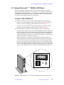
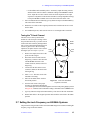
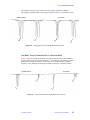
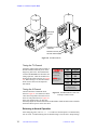
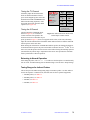
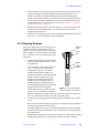
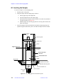
1.1 Overview of NMR Probe Hardware
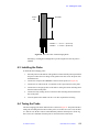
The basic probe system consists of
three parts (see Figure 1):
• The upper barrel is used as a
mechanism to deliver the
sample into the center of the
magnet. This part also
contains the apparatus for
spinning the sample. The
upper barrel is inserted into
the magnet from the top until
it seats on the room
temperature (RT) shim coil.
Typically, it remains in the
magnet.
• The probe, the lower part of
the probe system, is inserted
into the magnet from below
and secured with
thumbscrews. The top of the
probe mates to the upper
barrel. The proper alignment
of these two parts, the upper
barrel and the probe, is
important for proper spinning
and probe performance.
• The room temperature shim
coils surround the probe and
are used to adjust magnet field
homogeneity.
01-999034-00 B0798
Upper
barrel
Mating surface of
upper barrel and
room temperature
shim coil
Room temperature
shim coil
Mating surface of
upper barrel and
probe
Probe
Figure 1. Probe, Upper Barrel, and RT Shim
Coil Configuration
Varian NMR Probes Installation
15
Chapter 1. Probe-Related Hardware
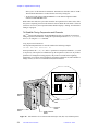
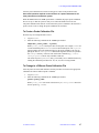
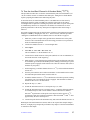
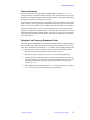
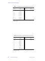
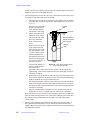
The procedures for connecting and tuning each probe are basically similar. The connectors
referred to in the cable connection instructions are found on the left magnet leg (or magnetconsole interface) and, if a UNITYINOVA, UNITYplus system, or a UNITY system with an
Oxford magnet, on the preamplifier assembly bolted to the magnet stand. Figure 2 shows
examples of various preamplifier configurations and Figure 18 shows the assembly for
UNITY
INOVA and UNITYplus systems.
Each probe in this manual is identified by the probe part number (the number shown on the
identification label attached to the probe) and the probe order number (the part number used
for ordering the probe). The probe order number identifies a probe kit, which includes the
probe assembly, a sample kit, and the probe installation manual.
Dual preamplifiers
XMTR
XMTR
TUNE
PROBE
J5313
J5303
J5321
PROBE
PROBE
J5311
J5301
1/4 WAVELENGTH
BROADBAND PREAMP
15 – 400MHz
991071
HB OBS/DCL
LB OBS/DCL
TUNE
OUTPUT
1H/19F OBS PREAMP
991072
J5323
OUTPUT
OUTPUT
J5312
J5302
Magnet Leg
1H/19F preamplifier
on the magnet leg
1/4
WAVELENGTH
1H/OBS/DEC
TUNE
1/4
WAVELENGTH
NORMAL
OBSERVE
XMTR
J5303
PROBE
J5301
1H/19F OBS PREA
969884
87-17886
OUTPUT
J5302
Figure 2. Dual and 1H/19F Preamplifiers
16
Varian NMR Probes Installation
01-999034-00 B0798
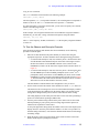
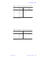
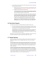
1.2 Installing the Pneumatic System
1.2 Installing the Pneumatic System
The pneumatic system for Varian and Oxford magnets uses quick-disconnect manifold,
valves, and push-in fittings. The fittings enable quick connects and disconnects by holding
the insert with two fingers and pushing the tubing in or pulling it out. Magnets are shipped
with a pressure regulator and oil filter for the air supply as well as a pressure regulator and
oil filter for the nitrogen supply.
The following procedure assumes that the probe is installed. If the probe is not yet installed,
skip step 1 until the probe is installed (see Section 1.3, “Installing the Probe and Upper
Barrel,” on page 18).
WARNING: Do not make any connections when the pneumatic system is under
pressure.
1.
Connect the COOLING Tygon tube to the probe (see Figure 3). Use the cooling air
meter, located inside the right-hand leg of the Varian magnet and on the preamplifier
housing of the Oxford magnet, to maintain a flow rate of about 10 liters/minute.
Rotation
Bearing
Eject
Quickdisconnect
connectors
Pressure regulator
(30 psig minimum)
N2 or Air
Supply
Upper
barrel
N2 or Air
Supply
Inlet filter
Oil filter
High temp
Plastic fitting
Probe body air
Low temp
Magnetconsole
interface
(magnet
leg)
Probe
VT transfer
dewar
Probe body air
On 500/51 and 600/51 systems
Pressure
regulator
Air
supply
Inlet filter
Oil filter
To shim coils
Figure 3. Pneumatic System Connection Diagram
01-999034-00 B0798
Varian NMR Probes Installation
17
Chapter 1. Probe-Related Hardware
2.
Connect the ROTATION, EJECT, and BEARING tubing to the upper barrel
assembly with quick-disconnect fittings. These fittings have an internal check valve
so air flow shuts off when they are disconnected.
3.
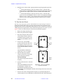
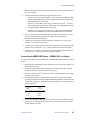
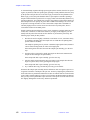
Connect the MANUAL
EJECT inlet tubing to the
left-leg manual eject
valve, and connect the
MANUAL EJECT outlet
tubing to the manual eject
valve outlet (see Figure 4).
4.
Install a 1/4 inch push-in
type fitting to each oil
filter outlet.
5.
Connect pressure
regulators with filters (air
only) to both the air and
nitrogen gas sources.
6.
Left-Hand Leg
or Oxford
Preamp. Housing
Manual Eject Button
1/8 Inch MPT Plug
Manual Eject Outlet
From Right-Hand Leg
or Within Oxford
Preamp. Housing
Manual Eject Inlet
From Right-Hand
Leg or Within
Oxford Preamp.
Housing
Connect the supply tubing
Figure 4. Manual Eject Valve
and nitrogen supply
tubing together, then
connect the tubing to either the air or nitrogen pressure regulator and filter system.
CAUTION:
The VT transfer dewar is made of glass, is not flexible, and should be
handled with care.
7.
For variable temperature (VT) operation, connect the “high temperature” tubing to
the heat exchanger (VT bucket) outlet, and connect the transfer dewar from the heat
exchanger outlet to probe inlet. The plastic fittings supplied with the VT kit allows
a solid connection between “low temperature” plastic tubing and the heat exchanger
(VT bucket) inlet.
8.
Increase the air or nitrogen gas pressure. If you find a leak between a tube and a
fitting, refer to Chapter 7, “Maintenance and Troubleshooting,” for troubleshooting
procedures..
Do not mix the two gases (air and nitrogen) within the probe. It is best to use one gas
for the whole system.
1.3 Installing the Probe and Upper Barrel
Use the procedure outlined in this section to install the upper barrel and probe for any probe
described in this manual. Refer to the section that describes the probe for further details on
connections and tuning.
WARNING: Keep your head away from the helium and nitrogen exit tubes and the
probe sample outlet. Do not look down the upper barrel unless the
probe is removed from the magnet.
CAUTION:
18
Probes contain fragile ceramic and glass parts. Avoid shock or
pressure that might damage these components. Do not drop the
probe. Do not drop anything down the top of the probe barrel.
Varian NMR Probes Installation
01-999034-00 B0798
1.3 Installing the Probe and Upper Barrel
To install the probe and upper barrel:
1.
2.
Determine that a test sample spins in the upper barrel before inserting the upper
barrel in the magnet:
a.
Connect the ROTATION, EJECT, and BEARING tubing to the upper barrel
assembly and start the air flow. (Refer to the Section 1.2, “Installing the
Pneumatic System,” on page 17.)
b.
With the top of the upper barrel tilted to no more than 30 from horizontal and
one hand placed over the bottom, place the sample and rotor into the top.
c.
Slowly raise the upper barrel to vertical. The sample should spin freely.
d.
Cover the top of the upper barrel with your hand and carefully tip the upper
barrel to eject the sample.
Carefully insert the upper barrel in the magnet without the probe in place.
Take care not to pinch off any of the air hose lines. The upper barrel makes contact
with the shim coil set at point B in Figure 1. Do not tighten the thumbscrews on the
upper barrel collar at this time.
3.
With a nonmagnetic hex-key wrench, loosen the three setscrews in the probe
mounting flange until the flange can be moved but the weight of the probe does not
cause the probe to slide out of the flange.
4.
Insert the probe into the magnet until it makes contact with the upper barrel at point
A in Figure 1. Push the probe and upper barrel assembly up and tighten the mounting
flange thumbscrews. Be sure to tighten the thumbscrews equally.
If the probe mounting plate has not been adjusted yet for the magnet, adjust the plate
as follows:
a.
Loosen the three setscrews in the mounting flange with the nonmagnetic hexkey wrench supplied, and move the mounting plate to 1/4 inch (6 mm) from
the lower end.
b.
Insert the probe into the magnet until it meets a stop. Do not force the probe
upward, because the upper barrel, held in place by only an O-ring, will move.
c.
Rotate the probe until the rf connectors are positioned, and then rotate the
mounting plate.
d.
Push the probe upwards until the plate is flat against the magnet surface.
e.
Secure the two flange thumbscrews to the magnet and gently tighten (1 to 2
inch-pound torque) the three setscrews on the flange.
5.
Rotate the probe until the VT connecting dewar (positioned on one of the magnet
legs) is in line with the lower probe dewar extension. Push down on the upper barrel
until contact is made at point B once more.
6.
Attach the upper barrel to the upper magnet flange by tightening the thumbscrews
on the upper barrel collar, then tighten the setscrews equally on the probe mounting
flange. Be sure not to over-tighten the setscrews.
CAUTION:
The setscrews should be just tight enough so the probe is firmly held
in the flange,. Be careful to not over-tighten because it is possible to
dent the shield.
01-999034-00 B0798
Varian NMR Probes Installation
19
Chapter 1. Probe-Related Hardware
1.4 Pneumatics/Tachometer Box
The room temperature (RT) and variable temperature (VT) Pneumatics/Tachometer Boxes
are used with Varian RT CP/MAS, Varian VT CP/MAS, and Doty Scientific solids probes
as well as with Varian Nano•nmr probes. The Pneumatics/Tachometer Box handles all air/
gas supply distribution to the probe. The supply line is permanently connected to the wall
supply, which must be clean, dry air. The wall supply should be at a pressure not exceeding
120 psig (8 bar) and be filtered to 0.6 micron.
CAUTION:
Failure to maintain a clean and dry air supply shortens probe life.
This section contains general information about the RT and VT Pneumatics/Tachometer
Boxes and installation instructions.
RT CP/MAS Pneumatics/Tachometer Box
Figure 5 shows the Pneumatics/Tachometer Box for RT (room temperature) CP/MAS
probes. The box is mounted on a magnet leg. The two hoses coming out of the left side of
the box are connected to the probe ROTATION/DRIVE and BEARING connectors. These
connectors are of high-pressure, quick-disconnect types.
The RT Pneumatics/Tachometer Box comes in two versions: either with or without an
independent power supply. If the box does not have its own power supply (for CP/MAS
operation), the tachometer cable (P6001) is disconnected from the upper barrel and
connected to the Molex socket on the box o provide power to the electronics in the box. A
tachometer sensor in the probe is also connected to the box with the cable provided.
Filter
Flow meter/valve
Bearing pressure
regulator and gauge
Bearing to probe
Supply in
Power socket for tach
cable from tach power supply
Rotation/drive to probe
Tachometer
display
Sockets for optical
fibers from probe
BNC connector for Doty
probe tach preamp (J6007)
Drive pressure
regulator and gauge
Figure 5. Pneumatics/Tachometer Box for RT CP/MAS Probes
VT CP/MAS Pneumatics/Tachometer Box
Figure 6 shows a Pneumatics/Tachometer Box for VT (variable temperature) CP/MAS
probes. This box is mounted on a leg of the magnet in a convenient position. The four hoses
coming out of the left side of the pneumatics box are connected to the probe ROTATION/
20
Varian NMR Probes Installation
01-999034-00 B0798
1.4 Pneumatics/Tachometer Box
Angle adjust tool
Flow meter/valve
Filter
Tachometer counter
Rotation/drive to probe
Drive pressure
regulator and gauge
Bearing to probe
N2 supply in
Rotation trigger adjust
Body N2 to probe
Bearing pressure
regulator and gauge
To eject port
of magnet
Body pressure
regulator and gauge
Purge to heat exchanger
Figure 6.
Pneumatics/Tachometer Box for VT and RT CP/MAS Probes
DRIVE, BEARING, BODY GAS, and the EJECT port of the magnet. These connectors are
of a high-pressure, quick-disconnect type.
Installing the Pneumatics/Tachometer Box
To install an RT or VT Pneumatics/Tachometer box:
1.
Using the hardware provided in the Pneumatics/Tachometer Box kit, install the box
on the magnet leg.
CAUTION:
Use only dry N2 for any VT work.
2.
Connect the inlet hose of the Pneumatics/Tachometer Box to a clean, dry supply of
compressed air or nitrogen. This supply should be at 90 psig continuous pressure.
3.
Close both the rotation/drive and bearing pressure regulators, and turn on the supply.
Check for air leaks by slowly opening both pressure regulators until a pressure of 10
psig shows on the gauges. No air should escape through the hoses. If air escapes,
check for grit in the probe connectors. When this test is complete, close both
regulators.
4.
Open the check valve of the air connector on each hose from the Pneumatics/
Tachometer Box to the probe. This is done by inserting a thin tool (such as a small
flat-head screwdriver) into the connector and pressing down until a click is felt.
5.
Turn the bearing regulator to show 10 psig. There should be a good flow rate shown
on the flow meter. If the flow is low, turn the needle valve on the flow meter counterclockwise until a good flow is obtained. Repeat this procedure for the drive supply.
Note that under normal circumstances, the bearing and drive flowmeter needle
valves are left in the full open position and are not used for control.
01-999034-00 B0798
Varian NMR Probes Installation
21
Chapter 1. Probe-Related Hardware
WARNING: When operating under high pressure, make sure the valves on older
flow meters are not too loose. Older flow meters have removable flow
knobs that can fly off if loosened too much when under high pressure.
6.
Install the Pneumatics/Tachometer Box power supply in the back of the rf cabinet.
7.
Install the cable from the power supply to the Pneumatics/Tachometer Box, routing
it with the other cables running to the magnet. Feed the coax terminated with a SMB
connector through the cabinet to the front of the digital card cage.
8.
Plug the SMB connector into the Acquisition Controller board at the EXT TIME
BASE position.
9.
Plug the probe fiber optic cables into the Pneumatics/Tachometer Box in one of the
following configurations:
• Varian probes – Switch to VA optic.
• Doty probes – On the Pneumatics/Tachometer Box, set the 3-position switch to
EXT NEG.
10. Plug the supply cord from the Pneumatics/Tachometer Box power supply into the
110 Vac distribution panel inside the rf cabinet (on the rear center).
11. Make sure that power is supplied to the Pneumatics/Tachometer Box by checking for
light from the optical connector of the Pneumatics/Tachometer Box. The LCD
display on the Pneumatics/Tachometer Box should also display a decimal point.
12. For Doty probes only, install the dummy optical plug (if supplied) into the optical
receiver connector of the Pneumatics/Tachometer Box.
13. For Doty probes only, connect the Doty tachometer amplifier optical output position
to the Pneumatics/Tachometer Box external input. Plug the power supply into a
source of 110 Vac. Move the switch on the tachometer amplifier marked optical off
to the position away from its label.
14. Restart the data station and the acquisition console.
15. Use the config program to set Rotor Sync to Present as described in the VNMR
and Solaris Software Installation Manual.
16. Connect a CP/MAS probe to the Pneumatics/Tachometer Box air hoses.
17. For Varian VT CP/MAS probes, connect the body N2 to the probe and adjust to 20
LPM 5 LPM for VT operation. We recommend that about 5 LPM body N2 be used
for ambient operation.
Replacing the Air/Gas Filter
Replace the blue disposable 0.6 micron particle filter (Part No. 27-180354-00) after it has
become discolored (turned red).
To install a new filter:
22
1.
Disconnect the filter by pressing the movable sleeve on the gas hose fitting toward
the tube fitting (you may need a small crescent wrench) and pulling the filter out of
the tube fitting.
2.
Insert a new filter, with the arrow on the filter pointing towards the probe.
3.
Return the movable sleeve to its original position.
Varian NMR Probes Installation
01-999034-00 B0798
Chapter 2.
Adjustments and Tuning
Sections in this chapter:
• 2.1 “Adjusting Spinning and Air Pressure” this page
• 2.2 “Using the qtune Graphical Probe Tuning Program” page 25
• 2.3 “Tuning Probes with UNITYINOVA or UNITYplus” page 33
• 2.4 “Tuning Probes with MERCURY-Series or GEMINI 2000 Systems” page 37
• 2.5 “Tuning Probes with UNITY or VXR” page 40.
• 2.6 “Tuning Probes with Gemini Systems” page 43.
• 2.7 “Setting the Lock Frequency on 600-MHz Systems” page 45.
• 2.8 “Changing Samples or Solvents” page 46.
• 2.9 “Testing a Probe” page 46.
• 2.10 “Using Probe Calibration Files” page 46.
Although the information in this chapter applies to all probes, tuning procedures differ
between spectrometers and are described in separate sections.
01-999034-00 B0798
Varian NMR Probes Installation
23
Chapter 2. Adjustments and Tuning
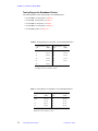
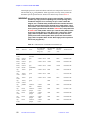
2.1 Adjusting Spinning and Air Pressure
For best results, operate the spinner (upper barrel) under the conditions shown Table 1 (the
“Standard” configuration column is for systems without the sample changer installed).
Table 1. Spinning Conditions With and Without a Sample Changer
Item
Standard
With Sample Changer
Upper barrel Part No.
00-948003-xx
00-958341-xx
Maximum sample size
16 mm
5 mm
Minimum sample size
5 mm
5 mm
Turbine color
green
white
System air pressure
26–28 psig1
18–20 psi
Bearing air valve
open about 1/2 turn
open about 1/4 turn
Slow drop air valve
open about 2 turns
closed
Sample depth2
69 mm
124 mm
Spin air pressure
not applicable
3–8 psig
1. PFG upper barrels require greater air pressure, typically 26–45 psi.
2. Maximum depth from the spinner bottom to the sample tube bottom.
To Adjust the Cooling Air
Adjust the COOLING AIR valve (located on the right magnet leg) for best performance. The
probe cooling air line is fed by this valve.
To Adjust the Bearing Air
Adjust bearing air as follows:
1.
Turn off bearing air valve.
2.
Turn the valve on again slowly until the console SPIN light starts flashing. Enter the
lock routine of acqi and make sure the spin speed is displayed on the screen.
3.
Open the bearing valve 1/16 turn more.
To Adjust System Air Pressure
Adjust the system air within the limits specified in Table 1 as necessary to optimize sample
insertion, ejection, and spinning. The VT air (or dry N2 gas) line must be connected to the
probe at all times when the probe is in use.
VT air is provided to the probe by placing the VT connecting dewar in line with the probe
dewar extension. Set the VT ball valve meter to read 5–10 LPM to start and reset as
necessary to optimize sample insertion, ejection, and spinning. Failure to attach the
necessary air components will cause difficulty in sample spinning and ejection, sample
cooling (decoupler heating), and possibly shimming.
Always use either the insert (i) and eject (e) commands or acqi to insert and eject the
sample, except on MERCURY, GEMINI 2000, or Gemini systems without Computercontrolled Insert/Eject Module installed.
24
Varian NMR Probes Installation
01-999034-00 B0798
2.2 Using the qtune Graphical Probe Tuning Program
2.2 Using the qtune Graphical Probe Tuning Program
This section describes how to use the graphical probe tuning program (shown in Figure 7)
for interactive NMR probe tuning on UNITYINOVA and UNITYplus systems, and on
MERCURY-VX systems equipped with the graphical tuning upgrade.
Figure 7. Tune Display Window and Tune Control Panel (qtune Program)
The qtune program runs on the host computer and provides the user with an interactive
tuning method that provides separate information for matching and resonant frequency.
This program is especially useful for tuning probes with complicated coil configurations,
such as imaging probes.
After the system is put into tune mode, the reflected power from the probe passes through
the directional coupler and is detected and digitized by the receiver circuitry: Any power
that the receiver detects is reflected power. Taking one (or more) complex pair of data points
at each frequency gives a data set that shows reflected power versus frequency. A coil tuned
to a specific frequency (usually the frequency of the nucleus the user wants to observe)
reflects little power at that frequency. The acquisition system then sweeps through the
desired frequency range and gathers data on reflected power interactively. The user can
adjust certain parameters in real-time during the experiment.
Tuning a Probe with qtune
This procedure describes how to use the qtune program to tune an NMR probe.
1.
Set up the system for tuning:
UNITY
INOVA and UNITYplus – leave the switch set to observe mode.
MERCURY-VX – connect the following cables:
• Connect the appropriate cable from the probe (J5102 or J5302) to the
TUNE J5402 connector on the inside of the magnet leg.
• Connect the appropriate cable from the transmitter (J5602 or J5603) to the
TUNE J5604 connector.
• Connect the appropriate cable from the receiver (J5303 or J5103) to the
Q TUNE J5403 connector.
• Enter tn='n' su, where n is the nucleus to be tuned (e.g. tn='H1').
01-999034-00 B0798
Varian NMR Probes Installation
25
Chapter 2. Adjustments and Tuning
2.
In the VNMR input window, enter qtune(gain,power), where gain and
power are appropriate gain and power values. Typical entries are qtune(20,65)
for UNITYINOVA and UNITYplus, and qtune(0,15) for MERCURY-VX. Generally
you want as low a gain value as possible with as high a power value as possible. If
qtune is entered without arguments, the default values of 50 for gain and 60 for
power are used.
The Tune Display and Tune Control windows open, similar to Figure 7. The Tune
Display is centered on the resonant frequency of the current experiment (sfrq).
To change the gain and power values, click Exit in the Tune Control Panel and
reenter the qtune command with more appropriate values.
3.
In the Display field, select Full or Minimal.
• Full display shows the network-analyzer-like graph, as shown in Figure 7.
• Minimal display simplifies the tune display by showing numerical values
instead of the graph, as shown in Figure 8. When sweeping over a range of
frequencies, the minimal display shows minimum reflected power and center
frequency. When in CW mode, the minimal display shows the average reflected
power and the current frequency. Several display controls on the Tune Control
Panel are disabled in minimal display mode, including cursors, grid, and
markers.
4.
In the Audio field, select On or Off.
If set to On, a volume slider becomes available and a sound is generated that
indicates how close the minimum reflection is to the center of the sweep window—
the lower the pitch of the sound, the closer the minimum reflection is to the center.
The sound immediately stops if the response lacks a discernible minimum reflection
or if CW mode is set.
To use the audio capability requires:
• An audio speaker on the Sun computer.
CW mode
Sweeping over
a range of frequencies
Figure 8. Minimal Display Mode for the Tune Display
26
Varian NMR Probes Installation
01-999034-00 B0798
2.2 Using the qtune Graphical Probe Tuning Program
• The probe tuned well enough so that a clearly discernible minimum reflection
exists in the signal.
• A range of frequencies sent to the probe (i.e, audio requires sweep mode rather
than CW mode).
5.
Place a marker on the resonant frequency to which you want to tune the probe as
follows (this option is not available in minimal display):
a.
In the Tune Control Panel (see
Figure 9), click on the triangle
next to one of the markers to open
a pull-down menu (Figure 13
shows the Marker 1 menu).
For more detail on using markers,
see the “Using Cursors, Grid, and
Markers” on page 29.
b.
In the menu, select the resonant
frequency to which you are tuning
the probe.
A marker corresponding to the
selected frequency appears in the
Tune Display window.
6.
In the Tune Control Panel, type values as
appropriate in the Span, Scale, and other
fields on the Tune Control Panel.
Using the dB scale usually facilitates
probe tuning. See the “Adjusting the
Span” on page 28.
7.
Adjust the tune and match capacitors
Figure 9. Tune Control Panel
while watching the Tune Display
window. Use the match capacitor to
increase the depth of the dip as much as possible. Use the tune capacitor to center
the dip on the marker created in step 5.
The dip displayed in the Tune Display window shows where little power is reflected
at the frequency being observed. The depth of the peak shows the accuracy of the
impedance matching of the probe coil to the transmitter and receiver. The horizontal
location of the dip shows the frequency at which little power is reflected. The goal
of probe tuning is to increase the depth of the peak (matching) while centering the
dip at the desired frequency.
8.
After the probe is tuned, click Exit. You are ready to begin the experiment.
Adjusting the Center Frequency
The center frequency is the resonant frequency to which the probe is to be tuned. A list of
center frequencies appears in the Center pull-down menu in the Tune Control Panel (see
Figure 10). This list of frequencies is read from the VNMR nuctable file.
Note that any frequency you type into the field will not be read until you press Return. This
applies to all text entry fields.
1.
In the Center field, click on the triangle to open the pull-down menu, then select a
frequency that equals or is close to the frequency you want.
01-999034-00 B0798
Varian NMR Probes Installation
27
Chapter 2. Adjustments and Tuning
2.
Adjust the frequency by typing a new value
in the Center field or by clicking the – and +
buttons.
The – or + buttons decrease or increase the value
by the width of one span.
If the center frequency is either typed in or changed
by the – or + button, user is displayed next to the
frequency. If the typed value happens to
correspond to a nuclear frequency in the pull down
menu, that nucleus is displayed.
If the new center is too close to either of the system
frequency limits, the span is decreased to allow the
new center to be accepted, the message window
will beep, and an error message will appear. If the
specified center is past either frequency limit, the
message window will beep, and an error message
will appear.
Adjusting the Span
The span is the sweep width, in MHz, used in the
Tune Display.
1.
Figure 10. Pull-Down Menu
For Center Frequencies
To decrease or increase the span to the next
in the series 1,2,5 10,20, etc., in the Span
field, enter a value or click the – or + button.
Setting the span to less than 1000 Hz causes
the message window to beep and an error
message to appear.
Setting the span to more than maximum
span causes the message window to beep
and an error message to appear.
Setting the span to a value beyond the
maximum or minimum frequencies causes
the span to decrease, the message window
to beep, and user warnings to appear.
2.
In the Span field, click on the triangle to
open the Span pull-down menu (see Figure
11).
• Select Last Span to return to the
previous span value
• Select Maximum Span to make the
spectrometer sweep from the minimum
to maximum allowable frequencies.
• Select CW to temporarily stop
frequency sweeping and to make the
Figure 11. Pull-Down Menu
transmitter put out a CW signal. This
For Span
sets the frequency to the currently
selected center frequency. This mode is useful for checking the reflected power
on the tune meter or for making other tests that require a fixed frequency.
28
Varian NMR Probes Installation
01-999034-00 B0798
2.2 Using the qtune Graphical Probe Tuning Program
Using Cursors, Grid, and Markers
Cursors and markers appear on the Tune Display window and are used the same way they
are used in VNMR. Cursors and markers are color coded and the frequency positions of
each are displayed on the bottom of the Tune Display. Cursor, grid, and marker controls are
not available in minimal display.
Cursors
In the Cursor field, the Tune Control Panel
provides three cursor modes (see Figure 12)
• Select Off to turn cursors off so that no
cursors are displayed.
Figure 12. Cursor and Grid Controls
• Select Line to display a single cursor that specifies one frequency. The frequency
position of the cursor and the signal amplitude at that frequency are displayed on the
bottom of the Tune Display window.
• Select Box to display two cursors for use with the Expand button (for setting the span
to a narrower range). After a region is expanded, the cursor mode switches back to the
Off mode. The frequency positions of the cursors, as well as the delta and the signal
amplitudes, are displayed on the bottom of the Tune Display window.
Grid
In the Grid field, select Off or On (see Figure 12)
to control a grid display in the Tune Display
window. The grid helps in reading the reflected
power levels off of the graph. The grid does not
slow down the drawing time of the graph.
Markers
In the Marker 1, Marker 2, and Marker 3 fields,
the Tune Control Panel provides three markers for
marking fixed frequencies. Each marker has a
pull-down menu (see Figure 13) that lists the
same nuclear frequencies and the Center pulldown menu. Each marker also has an entry field
for entering a frequency.
You can use markers for observing fixed
frequencies, for example the two nuclear
frequencies of a double tuned probe. You can then
vary the span, and the markers will appear and
disappear, depending on whether their
frequencies are being scanned in the current
experiment.
Attempting to set the markers to values beyond
the system frequency limits causes the message
window to beep and produces an error message.
Figure 13. Pull-Down Menu
for Marker 1
01-999034-00 B0798
Varian NMR Probes Installation
29
Chapter 2. Adjustments and Tuning
Changing the Vertical Scale
You can change the vertical scale of the Tune Display window by selecting whether the data
is scaled in a linear or logarithmic manner (see Figure 14).
1.
In the Scale field, the Tune Control panel
provides two scaling modes:
• Select dB to provide a logarithmic
scale in units of dB.
• Select Linear to a linear scale with
Figure 14. Scale Controls
arbitrary units.
The dB scale shows a deeper dip for more accurate match adjustment.
2.
In the Max field, type a value you want for the top line in the Tune Display.
Setting a Max value beyond system limits generates a beep and an error message.
3.
In the Step field, type a value you want for the number of units per division mark of
the current scale (dB or linear) on the y axis of the Tune Display.
Step helps by making the height of a probe resonance appear larger or smaller.
Setting a Scale value beyond system limits generates a beep and an error message.
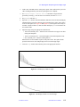
Calculating the Q Value
Probe Q factor determines sensitivity. Q is defined as the frequency of the resonant circuit
divided by the half-power bandwidth.
To calculate the Q value:
1.
In the Q calculation field, select On.
The current Q value and resonant frequency appears at the top of the Tune Display
window, and a horizontal cursor appears on the plot.
2.
In the Tune Display window, use the middle mouse button to place the horizontal
cursor on the base line (reflected power level outside of the resonance line).
The Q calculation appears at the top of the Tune Display window.
The Q value shown is determined as follows:
• The software finds the lowest point on the display and designates this as the resonance
Vmin. The frequency displayed is, at best, only as accurate as the frequency difference
between points. You must take this into account when quoting Q measurements.
• The software takes the level of the horizontal cursor as the baseline, or Vmax, which is
assumed to be a frequency where all the rf energy is reflected by the probe.
• The frequencies ω1 and ω2 have the following signal level.
V max
----------5
[Eq. 1]
• Q is calculated from the following equation, where ωr is the resonant frequency
ωr
[Eq. 2]
Q = --------------------ω1 – ω2
• The software checks that the low point (the bottom of the dip) is at least 15 dB below
the baseline. If this is not true, the calculated Q value is not accurate, and is, therefore,
not reported (the string “- - -” appears in the Q value field). The resonance
frequency, however, is still given.
30
Varian NMR Probes Installation
01-999034-00 B0798
2.2 Using the qtune Graphical Probe Tuning Program
Calibrating the Tune System
A Tune Calibration window is available for calibrating the tune system using a shorting
load, an open load (no device attached), and a 50-ohm load.
To calibrate the tune system.
1.
Set up the system for tuning:
UNITY
INOVA UNITYplus – Leave the switch set to observe mode.
MERCURY-VX – Connect the following:
• Connect the appropriate cable from the probe (J5102 or J5302) to the
TUNE J5402 connector on the inside of the magnet leg.
• Connect the appropriate cable from the transmitter (J5602 or J5603) to the
TUNE J5604 connector.
• Connect the appropriate cable from the receiver (J5303 or J5103) to the
Q TUNE J5403 connector.
• Enter tn='n' su, where n is the nucleus to be tuned (e.g., tn='H1').
2.
Click the Calibrate button on the Tune
Control Panel. The Tune Calibration
window opens (see Figure 15).
You must run the calibration tests in the
following order:
• Short Test
• Open Test
• 50 Ohm Test
Figure 15. Tune Calibration Window
The test buttons are only available in
this order.
The program stores only correction coefficients in files. Therefore, you will not be
able to view old calibration sweeps after the experiments are finished.
3.
In the Correction field, select Off or On to disable or enable calibration corrections,
respectively. The default is enabled.
If valid calibration files are not present, this button is not available.
4.
Connect a shorting load:
•
UNITY
INOVA and UNITYplus – Connect a shorting load to the tune port.
• MERCURY-VX – Connect a shorting load to TUNE J5402 on the inside (probe
side) of the magnet leg.
5.
Click the Short Test button.
6.
Remove the shorting device from the tune port.
7.
With no load on the tune port, click the Open Test button.
The program divides the full range of the spectrometer into 32 frequency bands and
runs 32 experiments. This data is merged into one high-resolution data set. After
enough data are collected, the Accept button becomes available. If ADC overflow
occurs, a warning message appears.
8.
After you see a strong signal (the signal will be stronger at low frequencies than at
high frequencies) that does not cause ADC overflow, click the Accept button.
9.
Attach a 50-ohm load:
01-999034-00 B0798
Varian NMR Probes Installation
31
Chapter 2. Adjustments and Tuning
•
UNITY
INOVA and UNITYplus – Connect the 50-ohm load to the tune port.
• MERCURY-VX – Connect the 50-ohm load to TUNE J5402 on the inside (probe
side) of the magnet leg.
10. Click the 50 Ohm Test button.
The program divides the full range of the spectrometer into 32 frequency bands and
runs 32 experiments. The data is merged into one high-resolution data set. After
enough data are collected, the Accept button becomes available. If ADC overflow
occurs, a warning message appears.
11. Click the Accept button and remove the 50-ohm load from the tune port.
12. After all three tests are finished, click the Save button.
The old calibration files are moved to .bak files, and new calibration files
std_ed.cal, std_es.cal, and std_er.cal are calculated. These files are
stored in $vnmrsystem/tune/tunecal. If the files cannot be saved, the
program produces a beep and an error message.
13. Click the Close button.
Restoring Previous Calibration Files
If you have an incorrect calibration file and do not want to re-run the calibration tests,
restore the previous calibration files:
1.
Click the Calibrate button on the Tune Control Panel. The Tune Calibration window
opens (see Figure 15).
2.
Click the Restore Backup button.
The program replaces the new calibration files
with the .bak files. If the program does not find
all of the backup files, an error message appears.
Restoring Original Calibration Files
System backup files can be installed by copying
the following .cal files on top of the
corresponding .sys files:
• std_ed.cal to std_ed.sys
• std_es.cal to std_es.sys
• std_er.cal to std_er.sys
To restore these system calibration files, click the
Restore Sys Backup button. The new calibration
files are replaced with the .sys calibration files
created at system installation.
Obtaining Online Help
To get online descriptions of the buttons and fields
in the Tune Control Panel, click the Help button
with the right mouse button. A pull-down menu
similar to that shown in Figure 16 appears. Select
the topic of interest from the menu.
32
Varian NMR Probes Installation
Figure 16. Help Pull-Down Menu
01-999034-00 B0798
2.3 Tuning Probes with UNITYINOVA or UNITYplus
2.3 Tuning Probes with UNITYINOVA or UNITYplus
This section describes tuning probes with UNITYINOVA and UNITYplus spectrometers.
Probes used with these systems can be tuned using one of two methods: using the TUNE
INTERFACE or using the graphical qtune program. For instructions on tuning probes
with MERCURY-VX, MERCURY, GEMINI 2000, UNITY, VXR, or Gemini spectrometers,
refer to the specific tuning procedure later in this section.
Using the TUNE INTERFFACE
UNITY
INOVA and UNITYplus systems use the TUNE INTERFACE for probe tuning:
• For 200-, 300-, and 400-MHz UNITYINOVA and UNITYplus spectrometers, the tune
interface is located on the Magnet-Console Interface, as shown in Figure 17.
• For 500-, 600-, and 750-MHz UNITYINOVA and UNITYplus spectrometers, the tune
interface is located on the Dual-Preamp Assembly, as shown in Figure 18.
The TUNE INTERFACE contains the following displays, readouts, and connectors:
• The liquid-crystal display at the top of the TUNE INTERFACE provides a digital and
analog view if the tune level. The center part of the meter displays a three-digit number
between 000 and 999 that indicates a probe tuning setting. The outer, analog display is
an elliptical bar graph with a range of 0 to 1000. The analog display is useful for seeing
a trend—if the signal is increasing or decreasing.
• Below the display are two single-digit readouts labeled CHAN and ATTEN. The
CHAN switch on the tune interface activates the tuning function and sets the frequency
to be tuned. Switch position 0 is for normal operation—no probe tuning. The other
positions, 1 through 4, set the tuning frequency to that of the corresponding channel,
and connect the output of channel 1’s frequency synthesizer to the input of the tuning
circuit. All probe tuning frequencies are generated by the synthesizer associated with
channel 1. The ATTEN switch is active only when a channel has been selected and
TUNE INTERFACE
100
300
FACE
0
300
400
414
500
INTER
TUNE
100
1000
0
1000
414
900
600
900
700
700
600
500
400
PROBE
C
H
A
N
1
3
A
T
T
E
N
J5321
C
H
A
N
1
3
A
T
T
E
N
PROBE
J5321
Figure 17. Tune Interface for UNITYINOVA and UNITYplus 200, 300, and 400 Systems
01-999034-00 B0798
Varian NMR Probes Installation
33
Chapter 2. Adjustments and Tuning
allows you to set the amount of attenuation. Attenuation is selected in units of 10 dB.
The maximum attenuation is 79 dB, which is selected by setting of 8.
• At the lower right of the TUNE INTERFACE is a red indicator light and a BNC
connector labeled PROBE J5321.
While in the tune mode, the system does not allow an acquisition to be started. Also, while
the system is acquiring, the tune mode cannot be entered. When the tune mode is selected
(CHAN is not set to 0), the Acquisition Status Window displays “Tuning” to indicate that
tuning is in progress.
To Establish Tuning Frequencies and Channels
The UNITYINOVA and UNITYplus TUNE INTERFACE offers two methods for setting up
tuning frequencies and channels—setting the experimental parameters (i.e., tn, dn, dn2,
and dn3) or using the tune command.
Using Experimental Parameters
The experimental parameters are entered similar to the following example:
tn='H1' dn='13C' dn2='15n' su
In an experiment, the tn, dn, dn2, and dn3 parameters correspond to channels 1, 2, 3, and
4, respectively. The required su command sets up the frequencies. If, however, any of these
parameters are changed for tuning purposes, they must be restored before beginning
acquisitions. If you do not want to disturb an experiment’s parameter set (and remember to
change it back), use the tune command instead, described below.
TUNE INTERFACE
100
300
0
300
1000
414
900
C
H
A
N
700
600
500
400
PROBE
C
H
A
N
3
1
400
414
500
ACE
INTERF
TUNE
100
1000
0
A
T
T
E
N
XMTR
J5321
XMTR
1
3
A
T
T
E
N
600
900
700
PROBE
J5321
PROBE
PROBE
J5311
J5301
PROBE
J5311
TUNE
OUTPUT
1H/19F
TH
LENG
1/4 WAVE
J5323
MP
EA
AND PR
BROADB 0MHz
15 – 40
991071
EAMP
OBS PR
991072
PROBE
J5301
OUTPUT
J5302
OUTPUP
OUTPUT
J5302
J5312
OUTPUT
J5312
TUNE OUTPUT
J5323
Figure 18. Tune Interface for UNITYINOVA and UNITYplus 500, 600, 750, and 800 Systems
34
Varian NMR Probes Installation
01-999034-00 B0798
2.3 Tuning Probes with UNITYINOVA or UNITYplus
Using the tune Command
The tune command is entered similar to the following example:
tune('H1','C13','N15')
The first argument ('H1') corresponds to channel 1, the second argument corresponds to
channel 2, and so on. The tune command does not require the su command.
If a desired frequency is not in the nucleus table, you can enter a frequency for a channel,
similar to the following example:
tune('ch4','H1','ch3',357.834)
In this example, 1H is assigned to channel 4 and 357.834 MHz is assigned to channel 3.
Alternatively, you can enter a string of the desired frequencies using the format:
tune(f1, f2, f3, f4)
where f1 is the frequency, in MHz, for channel 1, f2 is the frequency assigned to channel
2, and so on.
To Tune the Observe and Decouple Channels
After the tuning frequencies and channels have been established, use the following
procedure to tune the probe.
1.
Move the rf cable attached to the probe channel you want to tune using the
appropriate step below. No filters should be in line during the tuning procedures:
•
UNITY
•
UNITY
INOVA and UNITYplus 200, 300, and 400 systems—disconnect the cable
from the H Band CM or B Band CM port on the back of the magnet-console
interface and connect it to the PROBE connector (J5321) on the TUNE
INTERFACE, which is on the front of the magnet-console interface shown in
Figure 17.
INOVA and UNITYplus 500, 600, and 750 systems—disconnect the cable
from the PROBE port on the broadband preamplifier (J5311) or the 1H/19F
preamplifier (J5301) and connect it to the PROBE port (J5321) on the TUNE
INTERFACE, which is located on the Dual Preamp assembly shown in Figure
18. Then disconnect the cable from the OUTPUT connector (J5312 or J5302)
and connect it to the TUNE OUTPUT connector (J5323).
The LED flashes to indicate that the tune configuration is not yet correct.
2.
Set the CHAN switch to the number of the channel to be tuned—1, 2, 3, and so on.
The LED turns off. The tuning meter is now activated and should display a number
in the digital display and a deflection on the analog display. The ATTEN switch
setting can be changed at this point to increase or decrease the meter reading.
The setting displayed in the center part of the meter can be reset later, permitting a
probe to be retuned while repeating its PW90 value.
3.
Tune the probe with the tuning controls on the probe. Refer to the section in this
manual pertaining to your specific probe for tuning ranges and the capacitor or
inductor sticks required for certain nuclei.
As the probe approaches being tuned, the number in the center of the liquid crystal
display decreases. Tune the probe until the number is as close to 0 as possible. To
facilitate tuning in the future, write down the channel and attenuator switch settings
and tuning voltage.
4.
When the probe is tuned, return the setting on the CHAN switch to 0 (the LED
flashes and the liquid crystal display turns off).
01-999034-00 B0798
Varian NMR Probes Installation
35
Chapter 2. Adjustments and Tuning
5.
Reconnect the rf cables in their original positions using the appropriate step below:
•
UNITY
•
UNITY
INOVA and UNITYplus 200, 300, and 400 systems—return the cable
connected to the TUNE PROBE connector (J5321) to the appropriate connector
on the back of the magnet-console interface (H Band CM or B Band CM).
INOVA and UNITYplus 500, 600, and 750 systems—return the cable
connected to the TUNE PROBE connector (J5321) to the appropriate PROBE
connector (J5311 or J5301). Then return the cable from the TUNE OUTPUT
connector (J5323) to the appropriate OUTPUT connector (J5312 or J5302).
The LED is now off.
To Tune the Lock Circuit
The lock circuit of the probe is factory-tuned and does not require tuning in normal use.
Follow the procedure below only if you have reason to believe the lock sensitivity has
degraded or after you have intentionally detuned the lock circuit. To gain access to the lock
tuning capacitors, the probe must be removed from the magnet after the sample is ejected.
Figure 19 shows two different layouts of the lock tune and match capacitors.
1.
Remove the sample from the probe.
2.
Remove the probe from the magnet.
3.
Disconnect the probe cable from the
Lock Preamp connector (P5205 in
the Magnet/Console Interface) and
connect it to the PROBE connector
(J5321).
4.
On 500-, 600-, and 750-MHz
systems, disconnect the cable from
the OUTPUT connector (J5312 on
the broadband preamp) and connect
it to the TUNE OUTPUT connector
(J5323).
Probe
shield
Lock
match
Lock
tune
The LED flashes to indicate the
tuning setup is not yet complete.
5.
6.
Enter the following command
exactly as shown (do not use single
quotes around the argument):
tune(lockfreq)
This sets the tuning circuit to the lock
frequency.
Probe
shield
Set the CHAN switch to 1. The LED
turns off.
Figure 19. Lock Tune and Match
The TUNE INTERFACE meter turns
Capacitors Locations
on and displays a number in the
digital display and a deflection on the
analog display. You can change the ATTEN switch setting to increase or decrease the
meter reading.
7.
36
Tune the lock circuit to the appropriate frequency by repeatedly tuning the two
variable capacitors accessed through two small holes in the outer shield of the probe.
Varian NMR Probes Installation
01-999034-00 B0798
2.4 Tuning Probes with MERCURY-Series or GEMINI 2000 Systems
8.
After the lock circuit is tuned, return the CHAN switch to 0 (the LED begins flashing
and the TUNE INTERFACE display turns off).
9.
Disconnect the cable from the PROBE connector (J5321) and return it to the Lock
Preamp (P5205 in the Magnet/Console Interface). The LED turns off.
10. On 500-, 600-, and 750-MHz systems, disconnect the cable from the TUNE
OUTPUT connector (J5323) and return it to the OUTPUT connector (J5312).
11. Reinsert the probe into the magnet.
2.4 Tuning Probes with MERCURY-Series or GEMINI 2000
Systems
These procedures describe how to tune probes used with MERCURY-series or
GEMINI 2000 spectrometer systems. The connectors used to tune to probe are located on
the back and inside of the left magnet leg and are illustrated in Figure 23.
MERCURY-VX systems can use the graphical qtune program for probe tuning, which is
described in Section 2.2, “Using the qtune Graphical Probe Tuning Program,” on page 25.
J5604
TUNE
J5603
13C/BB
J5602
1H/19F
J5601
2H
J5402
TUNE
J5102
1H
J5302
13C
J5304
J5103
1H/13F OUT
J5303
13C/BB OUT
J5203
2H OUT
J5305
5202
2H
J1
J3
LOCK
PROBE
J2
BB OBS
PROBE
J4
J5403
Q TUNE
Figure 20. Connectors Used for Tuning MERCURY or GEMINI 2000 Probes
01-999034-00 B0798
Varian NMR Probes Installation
37
Chapter 2. Adjustments and Tuning
Tuning the High-Band Observe and Decouple Channel
1.
Join an appropriate experiment and enter tn='xx' su, where xx is the nucleus
you want to observe, for example, tn='H1' for 1H or tn='F19' for 19F.
If the nucleus is not in the nucleus table, use sfrq instead of tn. Set sfrq to the
nearest frequency you want to observe, and then type su. Once the correct frequency
is determined, you can tune the probe.
2.
On the inside of the left magnet leg, locate the cable connected to the 1H (J5103)
connector. Disconnect this cable and connect to the TUNE (J5402) connector.
3.
On the back of the magnet leg, locate the cable connected to the 1H/19F (J5602)
connector. Disconnect this cable and connect it to the TUNE (J5604) connector.
4.
Turn on the transmitter with the appropriate command:
• 1H/13C GEMINI 2000, enter htune.
• 4-nucleus or broadband MERCURY-series or GEMINI 2000 enter btune.
5.
Set the meter switch to the TUNE position. Adjust the TUNE knob for a mid-range
reading.
6.
Alternately adjust the tuning controls and the match control to obtain a minimum
reading on the PROBE TUNING meter. Adjust the two tune controls so that each
tune capacitor has an equal capacitance. Adjust the TUNE LEVEL attenuator or 10position knob on the magnet leg to keep the PROBE TUNING meter in the lower
half of the meter scale.
7.
After a minimum has been obtained, enter tuneoff to turn off the transmitter.
8.
Return the cable from the TUNE (J5604) connector to the 1H/19F (J5602) connector,
return the cable from the TUNE (J5402) connector to the 1H (J5102) connector, and
set the tune meter switch back to SPIN.
Tuning the Low-Band Observe Channel
1.
Join an appropriate experiment and enter the appropriate value for tn:
• 1H/13C systems, enter tn='C13' su.
• 4-nucleus or broadband systems, enter tn='xx' su, where xx is the nucleus
you want to observe, for example, 'C13' for 13C or 'P31' for 31P.
If the nucleus is not in the nucleus table, use sfrq instead of tn. Set sfrq to
the nearest frequency you want to observe, and then enter su. Once the correct
frequency is determined, you can tune the probe.
2.
Move the cable from the 13C connector (J5302) to the TUNE connector (J5402).
3.
For broadband systems, make sure the correct 1/4-wavelength cable is attached.
4.
Move the cable from the 13C connector (J5603) on the rear of the magnet leg to the
TUNE connector (J5604) just above it.
5.
Turn on the transmitter board for tuning with the appropriate command:
• 1H/13C GEMINI 2000, enter ctune.
• 4-nucleus or broadband MERCURY-series or GEMINI 2000, enter btune.
38
6.
Place the meter switch in the TUNE position. Adjust the TUNE control knob for a
mid-range reading.
7.
Tune the probe using the appropriate step:
Varian NMR Probes Installation
01-999034-00 B0798
2.4 Tuning Probes with MERCURY-Series or GEMINI 2000 Systems
• For 1H/19F probes—turn the 13C coil tuning (green) and 13C coil matching
(blue) controls to obtain a minimum tuning meter reading as follows: Turn the
green control until meter reads a minimum reading. Then turn the blue control
for a minimum meter reading. Adjust the TUNE knob if needed. Switch back
and forth between the green and blue controls until you achieve an absolute
minimum meter reading. If the tuning is far off, it may be better to turn each
control past the minimum meter reading before turning the other control.
• For broadband and switchable probes—alternately adjust the tuning controls
and the match control to obtain a minimum reading on the PROBE TUNING
meter. Adjust the two tune controls so that each tune capacitor has an equal
capacitance. Adjust the TUNE LEVEL attenuator or 10-position knob on the
magnet leg to keep the PROBE TUNING meter in the lower half of the meter
scale.
8.
Once a minimum has been obtained, enter tuneoff to turn off the transmitter.
9.
Return the two cables to their original positions and switch the tune meter switch
back to SPIN.
Tuning the 2H Lock Channel
The lock circuit is factory-tuned and in
normal use will not require retuning. Follow
the procedure below only if you have reason
to believe the lock sensitivity has degraded
or after you have intentionally detuned the
lock circuit. To gain access to the lock
tuning capacitors, the probe must be
removed from the magnet after the sample is
ejected.
Probe
shield
Lock
match
Lock
tune
1.
Remove the sample, then remove the
probe from the magnet.
2.
Disconnect the lock cable from the
magnet leg. Connect a cable from the
LOCK PROBE connector to the
TUNE connector (J5402) on the left
magnet leg.
3.
Connect the 2H cable to the TUNE
connector (J5604) on the back of the
left magnet leg.
4.
Enter dtune. This turns on the lock
transmitter for tuning.
5.
Move the TUNING meter switch to
the TUNE position.
6.
Tune the lock circuit to the proper frequency by alternately adjusting the two
variable capacitors accessed through the two holes in the probe shield as shown in
Figure 21. Continue until a minimum reading is obtained on the TUNING meter.
7.
Enter tuneoff to turn off the lock transmitter.
8.
Return both cables to the original positions and switch the meter back to the SPIN
position.
01-999034-00 B0798
Probe
shield
Figure 21. Lock Tune and Match
Capacitors Locations
Varian NMR Probes Installation
39
Chapter 2. Adjustments and Tuning
2.5 Tuning Probes with UNITY or VXR
Use the following procedures to tune probes used with UNITY and VXR spectrometer
systems.
Tuning High-Band Observe and Decouple Channels
1.
Enter the value for the transmitter nucleus parameter by entering tn='xx' su,
where xx is the description of the desired observe nucleus, for example, tn='F19'
su or tn='H1' su.
2.
Move the rf cable from the high band channel you want to tune using the appropriate
step below. Do all tuning without filters in line:
• 200-, 300-, and 400-MHz systems with a 1H/19F preamplifier—Disconnect the
cable from the 1H/OBS/DEC port on the magnet leg and connect it to the tune
port on the magnet leg.
• 200-, 300-, and 400-MHz systems with a broadband preamplifier—Disconnect
the cable from the H Band port on the switching relay or the 1H/OBS/DEC port
on the magnet leg and connect it to the TUNE port on the magnet leg.
• 500-MHz systems with a 1H/19F preamplifier—Disconnect the cable from the
PROBE port on the preamplifier and connect it to the TUNE port on the magnet
leg.
• 500- and 600-MHz systems with a dual preamplifier—Disconnect the cable
from the PROBE port (J5301) and connect it to the TUNE PROBE port (J5321).
Disconnect the cable from the OUTPUT port (J5302) and connect it to the
TUNE OUTPUT (J5323).
• 500- and 600-MHz decoupler—Disconnect the cable from the band pass filter
on the side of the magnet leg and connect it to the TUNE PROBE port (J5321).
Disconnect the cable from the OUTPUT port (J5302) and connect it to the
TUNE OUTPUT port (J5323).
3.
Turn the tuning selector to the OBS position and adjust the TUNE LEVEL switch to
produce a signal on the PROBE TUNING meter.
This routes a continuous wave (CW) observe transmitter signal to the observe coil.
Unless the probe is perfectly tuned, the meter should register some deflection after a
momentary delay. At this point, the transmitter light on the console or the remote
status unit (as appropriate for your console) turns on. The receiver gain overload
light may come on also.
4.
Refer to the section in this manual that covers your probe for details on what tuning
controls to adjust for optimum tuning and for tuning ranges.
5.
Return the rf cables to the original positions using the appropriate step below:
• 200-, 300-, and 400-MHz systems with a 1H/19F preamplifier—Disconnect the
cable from the TUNE port on the magnet leg and connect it to the 1H/OBS/DEC
port on the magnet leg.
• 200-, 300-, and 400-MHz systems with a broadband preamplifier—Disconnect
the cable from the TUNE port on the magnet leg and connect it to the H Band
port on the switching relay or the 1H/OBS/DEC port on the magnet leg.
• 500-MHz systems with a 1H/19F preamplifier—Disconnect the cable from the
TUNE port on the magnet leg and connect it to the PROBE port on the
preamplifier.
40
Varian NMR Probes Installation
01-999034-00 B0798
2.5 Tuning Probes with UNITY or VXR
• 500- and 600-MHz systems with a dual preamplifier—Disconnect the cable
from the TUNE PROBE port (J5321) and connect it to the PROBE port (J5301).
Disconnect the cable from the TUNE OUTPUT (J5323) and connect it to the
OUTPUT port (J5302).
• 500- and 600-MHz decoupler—Disconnect the cable from the TUNE PROBE
port (J5321) and connect it to the band pass filter on the side of the magnet leg.
Disconnect the cable from the TUNE OUTPUT port (J5323) and connect it to
the OUTPUT port (J5302).
Tuning Low-Band Observe and Decouple Channels
1.
Enter the value for the transmitter nucleus parameter by entering tn='xx' su,
where xx is the description of the desired observe nucleus, for example,
tn='C13' su to set up 13C.
2.
If the nucleus you are using requires a capacitor or inductor stick, insert it into the
access hole at the bottom of the probe. Slide it into the probe until it stops, rotate it
two or three times until it seats. For the correct stick refer to the tuning range section
of the probe you are using.
3.
Remove all filters for the tuning operation.
4.
Move the rf cable attached to the X Channel you want to tune using the appropriate
step below. Remove all filters for the tuning operation.
• 200-, 300-, and 400-MHz systems with a 1H/19F preamplifier—Disconnect the
cable from the NORMAL port on the magnet leg and connect it to the TUNE
port on the magnet leg.
• 200-, 300-, and 400-MHz systems with a broadband preamplifier—Disconnect
the cable from the B Band port on the switching relay or the 1H/OBS/DEC port
on the magnet leg and connect it to the TUNE port on the magnet leg.
• 500-MHz systems with a 1H/19F preamplifier—Disconnect the cable from the
NORMAL port on the preamplifier (or from the DCPLR port on the switching
relay, located on the side of the magnet leg) and connect it to the TUNE port on
the magnet leg.
• 500- and 600-MHz systems with a dual preamplifier—Disconnect the cable
from the PROBE port (J5311) and connect it to the TUNE PROBE port (J5321).
Disconnect the cable from the OUTPUT port (J5302) and connect it to the
TUNE OUTPUT (J5323).
• 500- and 600-MHz decoupler—Disconnect the cable from the band pass filter
on the side of the magnet leg and connect it to the TUNE PROBE port (J5321).
Disconnect the cable from the OUTPUT port (J5302) and connect it to the
TUNE OUTPUT port (J5323).
5.
Turn the tuning selector switch to the OBS position and adjust the TUNE LEVEL
switch to produce a signal on the PROBE TUNING meter.
This routes a continuous wave (CW) observe transmitter signal to the observe coil.
Unless the probe is perfectly tuned, the meter should register some deflection after a
momentary delay. At this point, the transmitter light on the console or the remote
status unit (as appropriate for your console) turns on. The receiver gain overload
light may come on also.
6.
Refer to the section in this manual that covers your probe for details on what tuning
controls to adjust for optimum tuning and for tuning ranges.
01-999034-00 B0798
Varian NMR Probes Installation
41
Chapter 2. Adjustments and Tuning
7.
Return the rf cables to the original positions using the appropriate step below:
• 200-, 300-, and 400-MHz systems with a 1H/19F preamplifier—Disconnect the
cable from the TUNE port on the magnet leg and connect it to the NORMAL
port on the magnet leg.
• 200-, 300-, and 400-MHz systems with a broadband preamplifier—Disconnect
the cable from the TUNE port on the magnet leg and connect it to the B Band
port on the switching relay or the 1H/OBS/DEC port on the magnet leg.
• 500-MHz systems with a 1H/19F preamplifier—Disconnect the cable from the
TUNE port on the preamplifier and connect it to the NORMAL port on the
magnet leg (or to the DCPLR port on the switching relay, located on the side of
the magnet leg).
• 500- and 600-MHz systems with a dual preamplifier—Disconnect the cable
from the TUNE PROBE port (J5321) and connect it to the PROBE port (J5311).
Disconnect the cable from the TUNE OUTPUT (J5323) and connect it to the
OUTPUT port (J5302).
• 500- and 600-MHz decoupler—Disconnect the cable from the TUNE PROBE
port (J5321) and connect it to the band pass filter on the side of the magnet leg.
Disconnect the cable from the TUNE OUTPUT port (J5323) and connect it to
the OUTPUT port (J5302).
Tuning the Lock Channel
The lock circuit of the probe is factory-tuned,
and in normal use will not require tuning.
Follow the procedure below only if you have
reason to believe the lock sensitivity has
degraded or after you have intentionally
detuned the lock circuit. To gain access to the
lock tuning capacitors, the probe must be
removed from the magnet after the sample is
ejected (see Figure 22).
1.
Set the spectrometer to observe 2H by
entering tn='H2' su.
2.
Remove the sample from the probe.
3.
Remove the probe from the magnet.
4.
Connect the rf cable using the
appropriate step below:
Probe
shield
Lock
match
Lock
tune
• For 200- through 500-MHz
systems—Connect a cable from
the LOCK port on the probe to
the TUNE port.
Probe
shield
• For 500 and 600-MHz systems
with a dual preamplifier—
Figure 22. Lock Tune and Match
Connect a cable from the LOCK
Capacitors Locations
port on the probe to the TUNE
PROBE port (J5321). Disconnect the cable from the OUTPUT port (J4302) and
connect it to the TUNE OUTPUT port (J5323).
5.
42
Turn the tuning selector switch to the OBS position and adjust the TUNE LEVEL
switch to produce a signal on the PROBE TUNING meter.
Varian NMR Probes Installation
01-999034-00 B0798
2.6 Tuning Probes with Gemini Systems
6.
Tune the lock circuit to the optimum frequency by repeatedly tuning the two variable
capacitors, accessed through two small holes in the outer shield of the probe, as
shown in Figure 22.
7.
Reconnect the lock channel.
2.6 Tuning Probes with Gemini Systems
These procedures describe how to tune probes used with Gemini spectrometer systems. The
connectors used to tune to probe are located on the back and inside of the left magnet leg
and are illustrated in Figure 23.
Tuning the High-Band Observe and Decouple Channel
1.
Join an appropriate experiment and enter TN=x SU, where x is the atomic number
for the nucleus you want to observe, for example, TN=1 SU for 1H and TN=19 SU
for 19F. (If the nucleus is not in the nucleus table, type NUDIS to verify, and then use
SFRQ instead of TN. Set SFRQ to the nearest MHz you want to observe, and then
type SU. Once the correct frequency is determined, you can retune the probe.)
J5604
TUNE
J5603
13C/BB
J5602
1H/19F
J5601
2H
J5402
TUNE
J5102
1H
J5302
13C
J5304
J5305
5202
2H
Figure 23. Connectors Used for Tuning Gemini Probes
01-999034-00 B0798
Varian NMR Probes Installation
43
Chapter 2. Adjustments and Tuning
2.
On the inside of the left magnet leg, locate the cable connected to the 1H (J5103)
connector. Disconnect this cable and connect to the TUNE (J5402) connector.
3.
On the back of the magnet leg, locate the cable connected to the 1H/19F (J5602)
connector. Disconnect this cable and connect it to the TUNE (J5604) connector.
4.
For a dual-frequency Gemini, enter HTUNE. For a broadband Gemini enter BTUNE.
This turns on the transmitter for tuning.
5.
Set the meter switch to the TUNE position. Adjust the TUNE knob for a mid-range
reading.
6.
Alternately adjust the tuning controls and the match control to obtain a minimum
reading on the PROBE TUNING meter. Adjust the two tune controls so that each
tune capacitor has an equal capacitance. Adjust the TUNE LEVEL attenuator (on the
preamplifier housing) to keep the PROBE TUNING meter in the lower half of the
meter scale.
7.
Once a minimum has been obtained, type any character and press the Return key.
This turns off the transmitter.
8.
Return the cable from the TUNE (J5604) connector to the 1H/19F (J5602) connector,
return the cable from the TUNE (J5402) connector to the 1H (J5102) connector, and
set the tune meter switch back to SPIN.
Tuning the Low-Band Observe Channel
1.
Join an appropriate experiment and enter the value for TN as described in
appropriate step below:
• For 1H/19F systems, enter TN=13 SU.
• For broadband systems, enter TN=x SU, where x is the atomic number for the
nucleus you want to observe, for example, TN=1 SU for 1H and TN=19 SU
for 19F.
If the nucleus is not in the nucleus table, type NUDIS to verify, and then use
SFRQ instead of TN. Set SFRQ to the nearest MHz you want to observe, and
then type SU. Once the correct frequency is determined, you can retune the
probe.
2.
Move the cable from the 13C connector (J5302) to the TUNE connector (J5402).
3.
Move the cable from the 13C connector (J5603) on the rear of the magnet leg to the
TUNE connector (J5604) just above it.
4.
For dual-frequency Gemini, enter CTUNE. For a broadband Gemini, enter BTUNE.
This turns on the transmitter.
5.
Place the meter switch in the TUNE position. Adjust the TUNE control knob for a
mid-range reading.
6.
Tune the probe using one of the steps below:
• For dual-frequency probes—turn the 13C coil tuning (green) and 13C coil
matching (blue) controls to obtain a minimum tuning meter reading as follows:
Turn the green control until meter reads a minimum reading. Then turn the blue
control for a minimum meter reading. Adjust the TUNE knob if needed. Switch
back and forth between the green and blue controls until you achieve an absolute
minimum meter reading. If the tuning is far off, it may be better to turn each
control past the minimum meter reading before turning the other control.
44
Varian NMR Probes Installation
01-999034-00 B0798
2.7 Setting the Lock Frequency on 600-MHz Systems
• For broadband and switchable probes—alternately adjust the tuning controls
and the match control to obtain a minimum reading on the PROBE TUNING
meter. Adjust the two tune controls so that each tune capacitor has an equal
capacitance. Adjust the TUNE LEVEL attenuator (on the preamplifier housing)
to keep the PROBE TUNING meter in the lower half of the meter scale.
7.
Once a minimum has been obtained, type any character and press the RETURN key.
This turns off the transmitter.
8.
Return the two cables to their original positions and switch the tune meter switch
back to SPIN.
9.
For broadband systems, make sure the correct 1/4-wavelength cable is attached.
Tuning the 2H Lock Channel
The lock circuit is factory-tuned and in
normal use will not require retuning. Follow
the procedure below only if you have reason
to believe the lock sensitivity has degraded or
after you have intentionally detuned the lock
circuit. To gain access to the lock tuning
capacitors, the probe must be removed from
the magnet after the sample is ejected.
1.
Remove the sample, then remove the
probe from the magnet.
2.
Disconnect the lock cable from the
magnet leg. Connect a cable from the
LOCK PROBE connector to the
TUNE connector (J5402) on the left
magnet leg.
3.
Connect the 2H cable to the TUNE
connector (J5604) on the back of the
left magnet leg.
4.
Enter DTUNE. This turns on the lock
transmitter for tuning.
5.
Move the TUNING meter switch to
the TUNE position.
Probe
shield
Lock
match
Lock
tune
Probe
shield
Figure 24. Lock Tune and Match
Capacitors Locations
6.
Tune the lock circuit to the proper
frequency by alternately adjusting the
two variable capacitors accessed through the two holes in the probe shield as shown
in Figure 24. Continue until a minimum reading is obtained on the TUNING meter.
7.
Type any character and press the RETURN key. This turns off the lock transmitter.
8.
Return both cables to the original positions and switch the meter back to the SPIN
position.
2.7 Setting the Lock Frequency on 600-MHz Systems
The potential for long-term drift of the Oxford 600-MHz magnet necessitates extending the
frequency range of the lock channel.
01-999034-00 B0798
Varian NMR Probes Installation
45
Chapter 2. Adjustments and Tuning
1.
Set the thumbwheels on the Offset Synthesizer board to 1500, and control the lock
frequency using PTS frequency synthesizer #3 in the third cabinet.
2.
Set the front panel knobs on the PTS to whatever setting is required to bring the lock
signal on resonance.
3.
The nominal setting for the synthesizer is 153.845000 MHz. Type this (or whatever
the final setting turn out to be) using the lockfreq parameter; for example:
lockfreq=153.845000
All internal frequency calculations will be appropriately adjusted.
2.8 Changing Samples or Solvents
Check the reading on the probe tuning meter when changing samples, when changing the
solvent at the same observe frequency, or when changing to a different observe frequency.
The tuning is sensitive to changes in the dielectric constant and ionic strength of the sample.
In severely lossy samples (for example, 0.1 M aqueous NaCl), the 90° pulse width can
increase dramatically. Check the pulse width with a similar sample doped with an
observable signal and determine a new value for the pulse width. This permits a more
rational choice of flip angle based on T1, the repetition rate, and the need for quantization.
Because the probe is a high-Q device, a lossy sample not only changes the value of the 90°
pulse width but also degrades the sensitivity even when properly tuned. The change in
sensitivity roughly parallels the change in 90° pulse width; that is, a doubling of the 90°
pulse width results in about a 50-percent loss in sensitivity. Keep this factor in mind when
choosing solvents.
With regard to sensitivity alone, a nonconducting or non-polar solvent is preferred.
Electrical conductivity of the sample is the primary contributor to its lossy character and
thus its probe detuning character.
2.9 Testing a Probe
The basic steps for testing a probe:
1.
Create a probe calibration file as described in Section 2.10, “Using Probe
Calibration Files,” this page.
2.
Follow the appropriate test procedures in the Acceptance Test Procedures manual
that shipped with your system or probe.
3.
After the appropriate tests are completed for the probe, print the corresponding
probe calibration file by entering the following command in the VNMR input
window:
ACreport
2.10 Using Probe Calibration Files
VNMR includes probe calibration files in the directory /vnmr/probes. Probe
calibration files contain pw90, tpwr, dmf, dpwr, and pwx settings for each probe used
with the system. GLIDE, automation, and manual operation using macros—including h1,
hcosy, and dept—retrieve appropriate power levels, the pw90 value, and the dmf value
46
Varian NMR Probes Installation
01-999034-00 B0798
2.10 Using Probe Calibration Files
from the probe calibration file, instead of using preset values in the parameters files.
Successful operation depends on the existence of a probe calibration file for
each probe that is used with the system.
When the MERCURY-series NMR spectrometer is installed, the proper probe calibration
files are set up, so that the system is ready to use when the installer leaves the site.
The probe calibration files must be created when the system is installed or the first time a
probe is used. Create or change the probe calibration file as follows:
To Create a Probe Calibration File
Do these steps for each probe that is tested.
1.
Log in as vnmr1.
2.
Enter the following command in the VNMR input window:
addprobe('probe_name','system')
Where probe_name is a descriptive name for the probe. For example, sw5mm for
a 5-mm switchable probe, or 4nucPFG for a 4-nucleus PFG probe. The 'system'
argument makes the probe calibration files for this probe available to all users by
placing the files in /vnmr/probes. Without the argument, the files are placed in
the vnmrsys directory of the user who entered the command (e.g., ~vnmr1/
vnmrsys/probes) and are only available to that user.
The values for power, pw90, dmf, and pp are initially set to 0 and filled in later by
running the calibration procedures for 1H, 19F, 31P, and 13C using GLIDE.
To Change to a Different Probe Calibration File
After the probes are tested and calibrated, use this procedure to switch to the appropriate
calibration file when a different probe is installed.
1.
Log in as vnmr1.
2.
Enter the following command in the VNMR input window;
probe='probe_name'
Where probe_name is the name of the directory in /vnmr/probes named for
the new probe (e.g., sw5mm).
01-999034-00 B0798
Varian NMR Probes Installation
47
Chapter 2. Adjustments and Tuning
48
Varian NMR Probes Installation
01-999034-00 B0798
Chapter 3.
Probes for Liquids NMR
Sections in this chapter:
• 3.1 “1H/13C Computer-Switchable RT Probes” page 50
• 3.2 “AutoSwitchable Probes” page 52
• 3.3 “Broadband Probes” page 67
• 3.4 “Indirect Detection Probes” page 74
• 3.5 “Switchable Probes” page 82
• 3.6 “Triple-Resonance Probes” page 87
Each Varian liquids NMR probe is covered in a separate section of this chapter. Covered in
the section are connecting the cables, tuning the probe, tuning ranges, and any special
information specific to the probe.
01-999034-00 B0798
Varian NMR Probes Installation
49
Chapter 3. Probes for Liquids NMR
3.1 1H/13C Computer-Switchable RT Probes
This section covers the following 1H/13C computer-switchable, room-temperature probes
for MERCURY-series, GEMINI 2000 or Gemini systems:
Magnet
(MHz)
Bore
(mm)
Sample Size
(mm)
Probe Part No.
200
54
5
00-966128-00
300
54
5
00-966128-01
These probes can observe 1H or 13C without being removed from the magnet. Software
controls switching by gating transmitters and preamplifiers at appropriate times. This
section is organized as follows:
• “Connecting to MERCURY-VX, MERCURY, GEMINI 2000, or Gemini,” this page
• “Tuning Controls” page 51
CAUTION:
Excessive heat can damage the sample, the decoupler coil and the
tuning capacitors in the switchable probe. Reduce heat by limiting
decoupler high power to 1.0 watts or less. Maintain an airflow of at
least 9.5 liters per minute through the probe dewar to cool the sample.
Connecting to MERCURY-VX, MERCURY, GEMINI 2000, or Gemini
1.
If the probe mounting plate has not been adjusted yet for the magnet, adjust the plate
as described in Section 1.3, “Installing the Probe and Upper Barrel,” on page 18.
2.
Insert the probe into the bottom of the magnet dewar. Secure the probe with the two
thumbscrews provided.
3.
Attach a 1H notch filter to the 13C connector (J5302) on the magnet leg. Connect a
cable from the filter to the OBS (green) connector on the probe.
4.
Make the following connections as appropriate for your system:
• On 200-MHz systems, attach a second 1H notch filter to the 2H connector
(J5202). Connect a cable from the notch filter to the LOCK (yellow) connector
on the probe.
• On 300-MHz systems, connect a cable from the 2H connector (J5202) to the
LOCK (yellow) connector on the probe.
50
5.
Connect the decoupler cable proton observe from the 1H connector (J5402) on the
magnet leg to the DEC (red) connector on the probe.
6.
Connect the cooling gas hose at the bottom of the probe housing to the cooling gas
supply hose through the double-barbed connector supplied. This will provide
cooling for the probe body and allows adjustment of temperature over a small range
near room temperature if the supply gas temperature can be varied.
Varian NMR Probes Installation
01-999034-00 B0798
3.1 1H/13C Computer-Switchable RT Probes
Tuning Controls
Computer-switchable probes have three controls that are operated by color-coded controls
extending from the bottom of the probe:
Function
Color
13C
green
blue
red
observe coil tuning
observe coil matching
1H observe/decoupler coil tuning
13C
The carbon observe coil tuning and matching controls are used to tune and match the
transmitter/receiver coil in the probe to resonance at the observe transmitter frequency. The
decoupler coil tuning control is used to tune the coil in the probe to resonance at the proton
transmitter frequency. The probe may need to be tuned after a sample or solvent is changed.
Refer to Section 2.8, “Changing Samples or Solvents,” on page 46 for details.
01-999034-00 B0798
Varian NMR Probes Installation
51
Chapter 3. Probes for Liquids NMR
3.2 AutoSwitchable Probes
AutoSwitchable probes combine simplified 4-nucleus operation with the versatility of
multinuclear broadband nuclear observation. This section covers the following
AutoSwitchable probes:
Magnet
(MHz)
Bore
(mm)
Sample
Range
(mm)
300
54
5
1
Probe Part No.
H/19F/13C/31P, 1H/19F/{15N–31P}
300 PFG
54
5
1
H/19F/13C/31P, 1H/19F/{15N–31P}
300 LH
54
5
1
300 PFG LH
54
5
1
19
13
31
1
19
15
31
H/ F/ C/ P, H/ F/{ N– P}
H/19F/13C/31P, 1H/19F/{15N–31P}
19
13
31
1
19
15
31
01-903109-01
01-904083-01
01-904086-01
01-904085-01
300
89
5
1
300 PFG
89
5
1
H/19F/13C/31P, 1H/19F/{15N–31P}
01-904084-01
01-904089-01
01-904090-01
H/ F/ C/ P, H/ F/{ N– P}
400 PFG
54
5
1H/19F/13C/31P, 1H/19F/{15N–31P}
400 PFG
89
5
1H/19F/13C/31P, 1H/19F/{15N–31P}
CAUTION:
01-903110-01
Do not attempt to tune the AutoSwitchable probe until you have
thoroughly read this section. Any slight altering of the tuning can
completely throw off the delicate balance between the two nuclei
resonant on a port.
This section is organized as follows:
• “Connecting the Probe,” this page
• “Tuning Controls” page 54
• “Tuning the Probe on UNITYINOVA and UNITYplus” page 56
• “Tuning the Probe on MERCURY and GEMINI 2000” page 58
• “Tuning Ranges for AutoSwitchable Probes” page 62
• “Using Capacitor Sticks” page 63
• “Tuning the X-CHANNEL from an Unknown State to 4 NUC Mode” page 63
• “Calibrating the MERCURY Reflection Meter” page 64
• “Tuning the Low-Band Channel in Switchable Mode” page 64
• “Tuning Tables for 4-Nucleus to Switchable” page 66
Connecting the Probe
The following sections describe how to connect an AutoSwitchable probe to a system.
To Connect to UNITYINOVA, UNITYplus, UNITY, or VXR
52
1.
If the probe mounting plate has not been adjusted yet for the magnet, adjust the plate
as described in Section 1.3, “Installing the Probe and Upper Barrel,” on page 18.
2.
Insert the probe into the bottom of the magnet dewar. Secure the probe with the
thumbscrews attached.
3.
For PFG probes only, connect the PFG cable to the PFG connector on the probe base
(see Figure 25).
4.
Connect the observe cable according to one of the following:
Varian NMR Probes Installation
01-999034-00 B0798
3.2 AutoSwitchable Probes
• 300- and 400-MHz systems with the 1H/19F OBS preamplifier – connect a
low-pass filter and lock reject filter to the OBSERVE NORMAL connector on
the magnet-console interface (magnet leg). Then connect a cable from the filter
to the OBS connector on the probe.
• 300- and 400-MHz systems with the broadband preamplifier – connect a
low-pass filter and lock reject filter to the B BAND connector or OBSERVE
NORMAL connector on the magnet-console interface (magnet leg). Then
connect a cable from the filter to the OBS connector on the probe.
5.
Attach a second notch filter to the LK PROBE connector (J5205) on the lock
preamplifier module inside the preamplifier housing. Connect a cable from the notch
filter to the LOCK connector on the probe.
6.
Connect the high-band cable according to one of the following:
• 300- and 400-MHz systems with the 1H/19F OBS preamplifier – connect a
high-pass filter to the 1H/OBS/DEC connector on the magnet-console interface
(magnet leg). Then connect a cable from the filter to the 1H/19F connector
(J6003) on the probe.
• 300- and 400-MHz systems with the broadband preamplifier – connect a
high-pass filter to the H BAND connector or the 1H/OBS/DEC on the magnetconsole interface (magnet leg). Then connect a cable from the filter to the 1H/
19F connector (J6003) on the probe.
Tuning counter
PFG connector
Counter label
Guide bore for 1/4-wave
and capacitor sticks
(shown with 1/4-wave stick)
High-band tuning controls
(shown in UP positions)
Low-Band tuning controls
(shown in DOWN position)
Low-band
match
High-band
match
Figure 25. AutoSwitchable PFG Probe Tuning Controls And Connectors
01-999034-00 B0798
Varian NMR Probes Installation
53
Chapter 3. Probes for Liquids NMR
7.
Connect the cable from the variable temperature (VT) controller to the 9-pin
connector (VT Control) on the probe.
8.
Connect the VT nitrogen gas hose to the stub tee on the glass dewar projecting to the
side at the base of the probe.
9.
Connect the body-cooling air hose to the hose barb protruding from the side of the
probe and adjust the air flow to 10–15 LPM (refer to Section 2.1, “Adjusting
Spinning and Air Pressure,” on page 24).
To Connect to MERCURY-Series, GEMINI 2000, or Gemini
1.
If the probe mounting plate has not been adjusted yet for the magnet, adjust the plate
as described in Section 1.3, “Installing the Probe and Upper Barrel,” on page 18.
2.
Insert the probe into the bottom of the magnet dewar. Secure the probe with the
thumbscrews attached.
3.
Attach the 1H high-pass filter to the 1H connector (J5102) on the magnet leg.
Connect a cable from the filter to the 1H/19F connector on the probe.
4.
Attach the low-pass filter to the 13C connector (J5302) on the magnet leg (if the
automation gradient relay is installed, use BB PRO J2). Connect a cable from the
filter to the 13C connector on the probe.
5.
Connect a 2H low-pass notch filter to the 2H connector (J5202) on the magnet leg (if
the automation gradient relay is installed, use LK PRO J3). Connect the cable to the
LOCK connector on the probe.
6.
For PFG probes only, connect the PFG cable to the PFG connector on the probe base
(see Figure 25).
7.
If the VT option is present, connect the cable from the VT controller to the 9-pin
connector (VT Control) on the probe. Connect the VT nitrogen gas hose to the stub
tee on the glass dewar projecting to the side at the base of the probe.
8.
Connect the body-cooling air hose to the hose barb (labeled AIR) on the probe and
adjust the air to 10–15 LPM. (refer to Section 2.1, “Adjusting Spinning and Air
Pressure,” on page 24).
Tuning Controls
The tuning controls for the AutoSwitchable probe extend from the bottom of the probe
base, as shown in Figure 25. The tuning controls of this probe are operated with the coaxial,
brass-colored tuning knobs. Both the high-band channel (labeled 1H/19F in red) and the
low-band channel (labeled X-CHANNEL in green) are tuned by independent controls
that control two resonances for each channel.
The match function is controlled by the smooth knob on the bottom, while the knurled
knob controls two tune functions: one in its DOWN position with the knob pushed all
the way down until the word DOWN becomes visible and the gear system for the
counter is engaged (for X-channel tuning), the other one in its UP position with the
word UP fully visible and the gear system engaged.
High-Band Tuning Characteristics
Figure 26 shows the tuning characteristics of the high-band tune controls. In the DOWN
position, both resonances are moved simultaneously, with clockwise rotation of the knob
54
Varian NMR Probes Installation
01-999034-00 B0798
3.2 AutoSwitchable Probes
increasing the frequency. In the UP position, the frequency separation is changed,
increasing the separation (while increasing the resonance frequency) by clockwise rotation.
DOWN position
UP position
19F
1H
19F
1H
Figure 26. Tuning Characteristics of High-Band Tune Controls
Low-Band Tuning Characteristics in 4-Nucleus Mode
Figure 27 shows the tuning characteristics of the low-band tune controls. In the DOWN
position, mainly the lower resonance frequency (13C) is changed, with clockwise rotation
of the knob increasing the frequency. In the UP position, mainly the upper resonance
frequency (31P) is changed, increasing the resonance frequency by clockwise rotation.
DOWN position
UP position
31P
13C
31P
13C
Figure 27. Tuning Characteristics of Low-Band Tune Controls
01-999034-00 B0798
Varian NMR Probes Installation
55
Chapter 3. Probes for Liquids NMR
Tuning the Probe on UNITYINOVA and UNITYplus
This section contains the following procedures for tuning the AutoSwitchable probe on
UNITY
INOVA and UNITYplus systems:
• “To Tune the High-Band Channel (1H/19F),” this page
• “To Tune the Low-Band Channel in 4-Nucleus Mode (13C/31P)” page 57
To tune AutoSwitchable probes with MERCURY or GEMINI 2000 systems, skip to
“Tuning the Probe on MERCURY and GEMINI 2000” page 58.
An AutoSwitchable probe is shipped from the factory pretuned for a specific system. To
obtain the best probe performance, tuning should be verified by running a pw90 calibration
on the observe nucleus. Follow the procedures in this section to retune the probe.
Read the entire procedure before starting. Normally, the high-band channel does not require
retuning and the broadband channel may need only a touchup.
To Tune the High-Band Channel (1H/19F)
This section contains the procedures used to tune the AutoSwitchable probe high-band
channel (1H/19F) on UNITYINOVA and UNITYplus systems. Tuning the high-band channel
requires preparing the NMR console and tuning the probe.
1.
Make sure you have a sample with typical dielectric characteristics in the probe.
Acetone is the recommended solvent for the tuning procedure to set up 4-nucleus
mode for automated operation.
2.
Connect the standard 1H/19F/13C 1/4-wavelength cable.
3.
Enter s2pul
4.
Enter dm='n' tn='H1' dn='F19' su
This sets channel 1 (observe channel) to the 1H frequency and channel 2 (decoupler
channel) to the 19F frequency.
5.
Connect the high-band connector of the probe (marked 1H/19F) to the TUNE
connector on the magnet leg.
6.
On the magnet leg, switch the channel selector to 2 (19F), and switch the attenuation
selector to 6.
7.
With the tune knob of the high-band channel (red label) in the DOWN position, tune
the probe until the meter readout is minimum. Use the match knob to reduce the
readout; repeat until the meter reads less than 50.
8.
Switch the channel selector to 1 (1H). Push the tune rod to the UP position, making
sure the gear system inside the probe is engaged. Tune and match until the meter
readout is minimized
9.
Repeat steps 6 and 7.
10. Switch the attenuation selector to 7 and repeat steps 6 and 7.
11. Switch attenuation selection to 8 and repeat steps 6 and 7 until both channels are
simultaneously less than 300.
12. Connect the probe back to the automation relay and switch the channel selector to 0.
Retuning the high-band channel is not required after sample changes or changes to the lowband channel. However, for highly lossy samples, the performance may improve if the
high-band channel is tuned again.
56
Varian NMR Probes Installation
01-999034-00 B0798
3.2 AutoSwitchable Probes
To Tune the Low-Band Channel in 4-Nucleus Mode (13C/31P)
This procedure describes how to tune the AutoSwitchable probe low-band channel (13C/
31P) in 4-nucleus mode on UNITYINOVA and UNITYplus. Tuning the low-band channel
requires preparing the NMR console and tuning the probe.
In 4-nucleus mode, the AutoSwitchable probe is switchable between four nuclei by
changing the frequency input in VNMR. No switching of the probe or the quarterwavelength cable is required for switching frequencies. Each of the two ports on the probe
is simultaneously tuned for two frequencies. The balance for each nucleus is set for
optimum performance at the factory and requires no adjustment after basic tuning is
achieved.
On systems equipped with only one PTS frequency synthesizer, the tuning nucleus must be
changed in VNMR by changing the value of tn. For best results, follow the procedure
“Tuning the X-CHANNEL from an Unknown State to 4 NUC Mode” on page 63.
1.
Make sure you have a sample with typical dielectric characteristics in the probe.
Acetone is the recommended solvent for the tuning procedure to set up 4-nucleus
mode for automated operation.
2.
Connect the standard 1H/19F/13C 1/4-wavelength cable.
3.
Enter s2pul.
4.
Enter dm='n' tn='P31' dn='C13' su.
This sets channel 1 to 31P and channel 2 to 13C.
5.
Connect the low-band connector of the probe (marked 13C/31P X CHANNEL) to
the TUNE connector on the magnet leg.
6.
Make sure the 1/4-wavelength stick is installed in the probe. Pull the tune rod of the
X CHANNEL (green label) to the DOWN position, making sure that the gear system
inside the probe is engaged. Set the counter to the value for 4-nucleus mode (refer to
the label on your probe).
7.
On the magnet leg, switch the channel selector to 2 (13C), and switch the attenuation
selector to 6.
8.
Tune the probe until the meter readout is minimum. Use the Match knob to reduce
the readout. Repeat until the meter reads less than 50.
9.
Switch the channel selector to 1 (31P). Push the tune rod in the UP position, making
sure that the gear system inside the probe is engaged. Tune until meter readout is
minimized. Do not move the Match knob.
10. Repeat the steps 7, 8, and 9.
11. Switch the attenuation selector to 7 and repeat steps 7, 8, and 9.
12. Switch the attenuation selector to 8. Repeat steps 7– 9 until the reflection readouts
are simultaneously less than 150 for channel 2 and less than 800 for channel 1.
Note that 31P performance of this probe can be improved at the expense of 13C
performance if this ratio of reflection readouts is altered such that 31P and 13C have
approximately the same reflected power.
13. Connect the probe back to the automation relay and switch the channel selector to 0.
Retuning the low-band channel in 4-nucleus mode is not required after sample changes.
However, for highly lossy samples the performance may improve if the low-band channel
is retuned for each sample.
01-999034-00 B0798
Varian NMR Probes Installation
57
Chapter 3. Probes for Liquids NMR
Tuning the Probe on MERCURY and GEMINI 2000
This section contains the procedures for tuning the AutoSwitchable probe on MERCURY
and GEMINI 2000 systems.
• “To Tune the Highband Channel (1H/19F),” this page
• “To Tune the Low-Band Channel in 4-Nucleus Mode (13C/31P)” page 60
To tune the AutoSwitchable probe with UNITYINOVA or UNITYplus systems, Use the
procedures in “Tuning the Probe on UNITYINOVA and UNITYplus” on page 56.
An AutoSwitchable probe is shipped from the factory pretuned for a specific system. To
obtain the best probe performance, tuning should be verified by running a pw90 calibration
on the observe nucleus. Follow the procedures in this section to retune the probe.
Read the entire procedure before starting. Normally, the high-band channel does not require
retuning and the broadband channel may need only a touchup.
To Tune the Highband Channel (1H/19F)
This section contains the procedures used to tune the AutoSwitchable probe high-band
channel (1H/19F) on MERCURY and GEMINI 2000 systems. Tuning the high-band channel
requires preparing the NMR console and tuning the probe.
1.
2.
Move the probe and the transmitter cables as follows:
a.
On the inside of the left magnet leg, locate the probe cable connected to the
H1 (J5102) connector. Disconnect this cable and connect it to the TUNE
(J5402) connector.
b.
On the back of the magnet leg, locate the transmitter cable connected to the
H1/F19 (J5602) connector. Disconnect this cable and connect it to the tune
(J5604) connector.
Start by tuning H1:
a.
Enter tn='H1' su.
b.
Turn on the transmitter board for tuning:
On a 1H/13C GEMINI 2000, enter htune.
On a MERCURY or broadband GEMINI 2000, enter btune.
3.
c.
Set the meter switch to the TUNE position. Adjust the TUNE knob for a
midrange reading on the TUNE meter.
d.
Enter tuneoff.
Tune F19:
a.
Enter tn='F19' su. Then enter htune or btune, depending on your
system:
1H/13C
GEMINI 2000, enter htune.
MERCURY or broadband GEMINI 2000, enter btune.
4.
b.
Check the TUNE METER reading.
c.
Enter tuneoff.
Tune H1:
a.
Set tn='H1' su. Then enter htune or btune, depending on your system:
1H/13C
58
GEMINI 2000, enter htune.
Varian NMR Probes Installation
01-999034-00 B0798
3.2 AutoSwitchable Probes
MERCURY or broadband GEMINI 2000, enter btune.
5.
b.
Check the TUNE METER reading for H1.
c.
With the tune knob of the high-band channel (red label) in the DOWN
position, tune the probe until the meter readout is minimum.
d.
Enter tuneoff.
Tune F19:
a.
Enter tn='F19' su. Then enter htune or btune, depending on your
system:
1H/13C
GEMINI 2000, enter htune.
MERCURY or broadband GEMINI 2000, enter btune.
b.
Check the TUNE METER. If the TUNE METER readings of both
frequencies are significantly below the previous readings from steps 2 and 3,
use both the UP and the DOWN positions to reduce the simultaneous reading
to this lower value. Do not use the match knob at this point.
c.
Enter tuneoff.
6.
Verify specifications at this tuning level. Continue with the next steps only if the
performance is insufficient.
7.
Tune F19:
a.
Enter tn='F19' su. Then enter htune or btune, depending on your
system:
1H/13C
GEMINI 2000, enter htune.
MERCURY or broadband GEMINI 2000, enter btune.
8.
b.
With the tune knob of the high-band channel (red label) in the DOWN
position, tune the probe until the meter readout is minimum. Turn the match
knob to minimize the TUNE meter readout.
c.
Alternate between the tune knob in the DOWN position and the match knob
to obtain a minimum reading on the PROBE TUNING meter.
d.
Adjust the TUNE LEVEL attenuation to keep the PROBE TUNING meter in
the lower half of the meter scale.
e.
After a minimum is obtain, enter tuneoff to turn off the transmitter.
Tune H1:
a.
Enter tn='H1' su.
b.
Enter htune or btune, depending on your system:
1H/13C
GEMINI 2000, enter htune
MERCURY or broadband GEMINI 2000, enter btune
c.
With the tune knob of the high-band channel (red label) in the UP position,
tune the probe until the meter readout is minimum. Turn the match knob to
minimize the TUNE meter readout.
d.
Alternate between the tune knob in the DOWN position and the match knob
to obtain a minimum reading on the PROBE TUNING meter.
e.
Enter tuneoff.
01-999034-00 B0798
Varian NMR Probes Installation
59
Chapter 3. Probes for Liquids NMR
9.
Repeat steps 3 through 8 until the PROBE TUNING meter reads mid-range or lower
for H1 and F19, simultaneously, when the TUNE LEVEL attenuation is
approximately at 3 o’clock.
Or, if the 10-position attenuator switch is installed, continue until the meter reading
is less than 10 at switch position 6.
10. Return the transmitter and probe cable as follows:
a.
Return the transmitter cable from the TUNE (J5604) connector to the H1/F19
(J5602) connector.
b.
Return the probe cable from the TUNE (J5402) connector to the H1/F19
(J5102) connector.
11. Set the tune meter switch to SPIN.
To Tune the Low-Band Channel in 4-Nucleus Mode (13C/31P)
This procedure describes how to tune the AutoSwitchable probe low-band channel (13C/
31P) in 4-nucleus mode on MERCURY and broadband GEMINI 2000 systems. Tuning the
low-band channel requires preparing the NMR console and tuning the probe.
For 1H/13C GEMINI 2000 systems, using the probe in 4-nucleus mode is not possible.
Instead, remove the 1/4-wavelength stick and use the 6.8 pF stick (red knob). Read this
section for cabling instruction, and then follow the procedure for observing 13C in the
switchable mode, as described in “To Tune 300- and 400-MHz Probes to 31P, 13C, or 15N”
on page 64.
In 4-nucleus mode, the AutoSwitchable probe is switchable between four nuclei by
changing the frequency input in VNMR. No switching of the probe or the quarterwavelength cable is required for switching frequencies. Each of the two ports on the probe
is simultaneously tuned for two frequencies. The balance for each nucleus is set for
optimum performance at the factory and requires no adjustment after tuning is achieved.
1.
Connect the standard 31P 1/4-wavelength cable.
2.
Enter s2pul.
3.
Move the probe and transmitter cables as follows:
a.
On the inside of the left magnet leg, locate the probe cable connected to the
C13 (J5302) connector. Disconnect this cable and connect it to the TUNE
(J5402) connector.
b.
On the back of the magnet leg, locate the transmitter cable connected to the
C13 (J5603) connector (if the automation gradient relay is installed, use BB
PRO J2). Disconnect this cable and connect it to the tune (J5604) connector.
4.
Check to see that the 1/4-wavelength stick is installed in the probe.
5.
Set the tune meter switch to TUNE.
6.
Tune C13:
a.
Enter tn='C13' su.
b.
Turn on the transmitter board for tuning:
For a 1H/13C GEMINI 2000, enter ctune.
For a MERCURY or a broadband GEMINI 2000, enter btune.
c.
60
Set the meter switch to the TUNE position. Adjust the TUNE knob for a midrange reading on the TUNE meter.
Varian NMR Probes Installation
01-999034-00 B0798
3.2 AutoSwitchable Probes
7.
d.
With the tune knob of the low-band channel (green label) in the DOWN
position, turn the knob until the counter is set to the value as shown on the
label for 4 NUC mode. Turn the match knob to minimize the TUNE meter
readout.
e.
Adjust the TUNE LEVEL attenuation to keep the PROBE TUNING meter in
the lower half of the meter scale.
f.
After obtaining a minimum, enter tuneoff to turn off the transmitter.
Tune P31:
a.
Enter tn='P31' su.
b.
With the tune knob of the low-band channel (green label) in the UP position,
tune the probe until the meter readout is minimum.
c.
After obtaining a minimum, enter tuneoff to turn off the transmitter.
8.
Repeat steps 6 and 7 until the PROBE TUNING meter reads mid-range on the TUNE
METER for 13C and 31P when the TUNE LEVEL attenuation is approximately at 3
o’clock. Or, if the 10-position attenuator switch is installed, continue until the meter
reading is less than 10 at switch position 6.
9.
Tune C13 again:
a.
Enter tn='C13' su
b.
Turn on the transmitter board for tuning:
For a 1H/13C GEMINI 2000, enter ctune.
For a MERCURY or a broadband GEMINI 2000, enter btune.
c.
Turn the match knob slowly to the right (counter-clockwise using the righthand rule) until the TUNE METER reads between 30 to 40.
d.
Enter tuneoff.
10. Return the transmitter and probe cables:
a.
Return the transmitter cable from the TUNE (J5604) connector to the C13/
P31 (J5603) connector.
b.
Return the probe cable from the TUNE (J5402) connector to the C13/P31
(J5302) connector (if the automation gradient relay is installed, use BB PRO
J2).
11. Set the tune meter switch to SPIN.
01-999034-00 B0798
Varian NMR Probes Installation
61
Chapter 3. Probes for Liquids NMR
Tuning Ranges for AutoSwitchable Probes
The following tables list the tuning ranges for AutoSwitchable probes. Use these tables as
a guide for choosing the appropriate capacitor or inductor sticks:
• For 300-MHz probes, see Table 2.
• For 400-MHz probes, see Table 3.
Table 2. Tuning Ranges for 300-MHz AutoSwitchable Probes
Capacitor Stick
(pF)
Range
(MHz)*
none
130–79 (31P)
6.8 (red knob)
81–61 (13C)
G 0 (blue knob)
63–49.8
G 18 (blue knob)
49.9–38.7
G 36 (blue knob)
38.8–32.8
G 51 (blue knob)
32.8–29.2 (15N)
1/4-wave (gold knob)
4-nucleus (13C/31P)
* Probe ranges are approximate and valid for empty probe
only. Ranges are slightly lower with a sample in a probe
Table 3. Tuning Ranges for 400-MHz AutoSwitchable Probes
Capacitor Stick
(pF)
Range
(MHz)*
none
170–93 (31P, 13C)
G 0 (blue knob)
95–45.8
G 18 (blue knob)
59–45.5
G 36 (blue knob)
46.2–39.5 (15N)
1/4-wave (gold knob)
4-nucleus (13C/31P)
* Probe ranges are approximate and valid for empty probe
only. Ranges are slightly lower with a sample in a probe
62
Varian NMR Probes Installation
01-999034-00 B0798
3.2 AutoSwitchable Probes
Using Capacitor Sticks
This procedure describes how to use the capacitor sticks, which extend the tuning range of
the probe. Refer to Table 2 and Table 3 for tuning ranges.
1.
Remove the capacitor stick from the protective shipping container.
The stick value is labeled at the bottom end of the stick. Notice that the new sticks
are color coded for easier identification:
• red knobs – regular capacitor sticks (not required for all probes)
• blue knobs – grounded capacitor sticks
• gold knobs – 1/4-wavelength sticks
The top of the stick has a flat region that serves as a key for proper orientation of the
capacitor stick in the probe.
2.
Insert the stick into the probe bottom until you feel the tip of the stick hit a barrier.
3.
Hold the plastic stick end (not the colored knob) and slightly rotate the stick until
you feel the key engage and the stick move inward slightly.
4.
Continue inserting the stick the rest of the way.
5.
When the threads of the stick knob touch the bottom of the probe, twist the knob to
affix the stick to the probe.
Tighten to finger-tight—overtightening could damage the probe.
Tuning the X-CHANNEL from an Unknown State to 4 NUC Mode
To tune the X channel from an unknown tuning state, you basically focus on 13C while
gently adjusting the match.
1.
Make sure that the 1/4-wavelength stick is installed and the correct sample is
inserted. Then set the counter (DOWN position) to the factory setting of 4 NUC (see
counter label on the probe).
2.
Set the console to 13C, and turn only the match knob to minimize the reflection
reading. The match capacitor should be only a few turns from minimum, turn it
counter-clockwise until it hits the stop; then, turn it about 5 turns clockwise again.
3.
Set the console to 31P, turn only the UP position to get the reflection minimum; then,
switch back to 13C and turn only the match to minimize 13C.
4.
Set the console to 31P and turn only the UP position to get the reflection minimum.
This gets you close enough to both frequencies to get started.
5.
Change back to 13C, turn the DOWN position and match to optimize the reflection.
The counter should remain fairly close to the factory-set value.
6.
Switch to 31P and turn only the UP position to minimize the reflection.
7.
Repeat steps 5 and 6 once.
8.
Add about a quarter-turn clockwise to match. Turn only the DOWN position to
minimize 13C; turn only the UP position to minimize 31P.
Do not adjust match anymore. The meter readout should be much better on 13C than
on 31P—about 4 to 5 times better on UNITYINOVA or about 10 units on MERCURY.
01-999034-00 B0798
Varian NMR Probes Installation
63
Chapter 3. Probes for Liquids NMR
Calibrating the MERCURY Reflection Meter
Calibrate the MERCURY reflection meter as follows.
1.
Disconnect the cable from the tune connector (J5602).
2.
Adjust the tune attenuation knob until the deflection is at the maximum meter
readout.
3.
Repeat this calibration after each switch in frequency
4.
Write down the meter readout for both frequencies for future reference.
5.
Reconnect the cable to the tune connector (J5602).
Tuning the Low-Band Channel in Switchable Mode
In switchable mode, the AutoSwitchable probe is similar in operation to any other
switchable probe. The high-band port is simultaneously tuned to 1H and 19F, while the lowband port is tuneable from 15N to 31P. For best results, use the correct 1/4-wavelength cable
and the standard filters (the 1H high-pass for the 1H/19F channel and the lock-reject and
low-pass filter for the 13C/31P/X channel).
Refer to the tuning ranges in Table 2 and Table 3 and select the appropriate capacitor stick.
This section contains the following procedures:
• “To Tune 300- and 400-MHz Probes to 31P, 13C, or 15N,” this page
• “To Tune 300-MHz Probes to 63–130 MHz” page 65
• “To Tune 300-MHz Probes to 30–63 MHz” page 65
• “To Tune 400-MHz Probes to 94–170 MHz” page 65
• “To Tune 400-MHz Probes to 39–94 MHz” page 66
To Tune 300- and 400-MHz Probes to 31P, 13C, or 15N
Use this procedure for tuning 300- and 400-MHz AutoSwitchable probes to 31P, 13C, or
15N.
1.
Set the spectrometer to observe the desired nucleus.
2.
With the standard sample in the probe, tune as follows:
•
31P
•
13C
•
13C
•
15N nucleus – Use the appropriate capacitor stick: G 51pF (blue knob) for 300-
nucleus – Use no capacitor stick. Preset the down tuner to the factory
counter value. Use the UP position and match to find the reflection minimum.
Match should be only a few turns from minimum (fully counterclockwise),
preset match first, then use the UP position to find the resonance. Iteratively
twist the UP position and match for optimum reflection.
nucleus, 300-MHz probes – Use the 6.8 pF capacitor stick (red knob).
Preset the counter to the factory value, leave match close to the 4-nucleus or 31P
setting, use UP position to find resonance. Use the UP position and match to
optimize.
nucleus, 400-MHz probes – Use no capacitor stick. Preset counter to
factory value, leave match close to the 4-nucleus or 31P setting, use UP position
to find resonance. Use UP position and match to optimize.
MHz probes or G 36pF (blue knob) for 400-MHz probes. Note that the UP
position tuner has no effect with capacitor sticks with the blue knob (G-type),
leave it in 4-nucleus position for easier return. Preset the counter to factory
64
Varian NMR Probes Installation
01-999034-00 B0798
3.2 AutoSwitchable Probes
value, add match (clockwise) to find resonance, use DOWN position and match
to optimize.
3.
Return cables to position prior to tuning.
To Tune 300-MHz Probes to 63–130 MHz
Use this procedure for tuning a 300-MHz AutoSwitchable probe to nuclei in the frequency
range of 63–130 MHz.
1.
Choose the appropriate capacitor stick (refer to Table 2):
• 79–130 MHz, no stick
• 63–79 MHz, 6.8 pF stick
2.
Preset the Broadband match knob to only a few turns from minimum (fully counterclockwise, then again several turns clockwise).
3.
Preset the counter by turning the Broadband tune knob in the DOWN position to a
value appropriate for the nucleus of interest. If you have operated your probe at this
frequency before, refer to your notes. Otherwise find an approximate value by
interpolating between 0 and the setting for 31P for frequencies above 79 MHz or
interpolating between 0 and 80 for frequencies in the range of 63–79 MHz.
4.
Turn the Broadband tune knob in the UP position and the match knob to find the
reflection minimum.
5.
Repeat with the tune knob in the UP position and the match knob to minimize the
reflection meter reading.
6.
Record the counter reading for future reference.
To Tune 300-MHz Probes to 30–63 MHz
Use this procedure for tuning a 300-MHz AutoSwitchable probe to nuclei in the frequency
range of 30–63 MHz.
1.
Use the appropriate capacitor stick (refer to Table 2).
2.
Turn the Broadband tune knob in the DOWN position to find the resonance. If you
have operated your probe at this frequency before, refer to your notes for the
appropriate counter setting.
Note that the UP position of the tune knob has no effect with grounded capacitor
sticks (blue knob), you can leave it in 4-nuc position for easier return to 4-nucleus
operation.
3.
Repeat with the tune knob in the DOWN position and the match knob to minimize
the reflection meter reading.
4.
Record the counter reading for future reference.
To Tune 400-MHz Probes to 94–170 MHz
Use this procedure for tuning a 400-MHz AutoSwitchable probe to nuclei in the frequency
range of 94–170 MHz. Use no capacitor stick.
1.
Preset the Broadband match knob to only a few turns from minimum (fully counterclockwise, then again several turns clockwise).
2.
Preset the counter by turning the Broadband tune knob in the DOWN position to a
value appropriate for the nucleus of interest. If you have operated your probe at this
01-999034-00 B0798
Varian NMR Probes Installation
65
Chapter 3. Probes for Liquids NMR
frequency before, refer to your notes. Otherwise find an approximate value by
interpolating between the settings for 13C and 31P.
3.
Turn the Broadband tune knob in the UP position and the match knob to find the
reflection minimum.
4.
Repeat with the tune knob in the UP position and the match knob to minimize the
reflection meter reading.
5.
Record the counter reading for future reference.
To Tune 400-MHz Probes to 39–94 MHz
Use this procedure for tuning a 400-MHz AutoSwitchable probe to nuclei in the frequency
range of 39–94 MHz.
1.
Insert the appropriate capacitor stick (refer to Table 3).
2.
Turn the Broadband tune knob in the DOWN position to find the resonance. If you
have operated your probe at this frequency before, refer to your notes for the
appropriate counter setting.
Note that the UP position of the tune knob has no effect with grounded capacitor
sticks (blue knob), you can leave it in 4-nuc position for easier return to 4-nucleus
operation.
3.
Repeat with the tune knob in the DOWN position and the match knob to minimize
the reflection meter reading.
4.
Record the counter reading for future reference.
Tuning Tables for 4-Nucleus to Switchable
This section provides a summary of tuning procedures for 4-nucleus to switchable
operation. For 300-MHz probes, see Table 4. For 400-MHz probes, see Table 5
Table 4. 300-MHz AutoSwitchable Tuning Summary
Nucleus
Match
Tune – UP
Tune–DOWN
Capacitor Stick
31P
clockwise
clockwise
counter1
none
13C
clockwise
clockwise
counter
6.8 pF (red knob)
counter
G51 pF (blue knob)
15N
clockwise
(no
effect)2
1. Counter settings are based on an empty probe.
2.Tuning in the up position does not affect the circuit when using grounded capacitor sticks.
Table 5. 400-MHz AutoSwitchable Tuning Summary
Nucleus
Match
Tune – UP
Tune–DOWN
Capacitor Stick
31P
clockwise
clockwise
counter1
none
13C
clockwise
counter-clockwise
counter
none
counter
G36 pF (blue knob)
15N
clockwise
(~ 10 turns)
(no
effect)2
1. Counter settings are based on an empty probe.
2.Tuning in the up position does not affect the circuit when using grounded capacitor sticks.
66
Varian NMR Probes Installation
01-999034-00 B0798
3.3 Broadband Probes
3.3 Broadband Probes
This section covers the following broadband probes:
Magnet
(MHz)
Bore
(mm)
Sample Size
(mm)
Range
Probe Part No.
200
54
5
20–81
00-969854-00
200
54
10
20–81
00-969847-00
200
89
10
20–81
00-969848-00
300
54
5
30–122
00-969841-00
300
54
10
30–122
00-969837-00
15
31
01-902660-00
300
51
10
300
89
5
30–122
00-969842-00
300
89
10
15
N–31P
01-902657-00
01-902244-00
N– P
400
51
10
15N–31P
400
89
10
15N–31P
01-902260-00
01-902289-00
500
51
5
15N–31P
500
51
10
15N–31P
01-902646-00
5
15N–31P
00-992554-00
600
51
This section is organized as follows:
• “Connecting to UNITY-Series or VXR,” this page
• “Connecting to MERCURY-Series, GEMINI 2000, or Gemini” page 68
• “Tuning the Broadband Probe” page 69
• “Returning to Normal Operation” page 70
• “Observing Protons” page 71
• “Using the Low-Frequency Broadband Probe” page 71
• “Tuning Ranges for Broadband Probes” page 72
Connecting to UNITY-Series or VXR
To connect a broadband•probe to a UNITYINOVA, UNITYplus, UNITY, or VXR system:
1.
If the probe mounting plate has not been adjusted yet for the magnet, adjust the plate
as described in Section 1.3, “Installing the Probe and Upper Barrel,” on page 18.
2.
Insert the probe into the bottom of the magnet dewar. Secure the probe with the two
thumbscrews provided.
3.
In the lock channel line, install the appropriate 2H bandpass filter listed in the
following table.
01-999034-00 B0798
Magnet (MHz)
2H
300
BE46-4-6BB
400
BE61-10-8BB
500
BE77-3.8-8BB
600
BE95-12-8BB
Bandpass Filter
Varian NMR Probes Installation
67
Chapter 3. Probes for Liquids NMR
Filter model numbers describe the filter’s function. For example, the 500-MHz
bandpass filter model number is BE77-3.8-8BB, where the 77 indicates 77 MHz and
“B” indicates bandpass—an “L” instead would indicate low-pass.
Expect the lock phase to change upon addition of the filter. Note that the 2H
bandpass filter can be left in the system at all times; however, it causes about 20%
loss in lock sensitivity
4.
Connect the observe channel according to the appropriate step below:
• For the 1H/19F OBS preamplifier, attach a low-pass filter to the OBSERVE
NORMAL or BB OBS/DCPL connector on the magnet-console interface
(magnet leg). Connect a cable from the low-pass filter to the OBS connector on
the probe.
• For the broadband preamplifier, connect a proton frequency low-pass filter to
the B BAND connector or the OBSERVE NORMAL on the magnet-console
interface (magnet leg). Connect a cable from the low-pass filter to the OBS
connector on the probe.
• For the dual preamplifier, connect a low-pass filter to J5311 on the preamplifier.
Connect a cable between the low-pass filter and the B BAND connector (K5008
NC). Connect a cable from the B BAND connector (K5008 CM) to the OBS
connector on the probe.
5.
Connect the decoupler channel according to the appropriate step below:
• For the 1H/19F OBS preamplifier, connect a high-pass filter to the 1H/OBS/DEC
or HB OBS/DCPL connector on the magnet-console interface (magnet leg).
Connect a cable from the high-pass filter to the DEC connector on the probe.
• For the broadband preamplifier, connect a high-pass filter to the H BAND or to
the 1H/0BS/DEC connector on the preamplifier. Connect a cable from the highpass filter to the DEC connector on the probe.
• For the dual preamplifier, connect a cable between the bandpass filter located on
the side of the preamplifier assembly and the DEC connector on the probe.
Connect a high-pass filter in series if the highband will be used as an observe
channel.
6.
Select an external quarter-wavelength cable to match the frequency of the observe
nucleus. Attach this cable between the two BNC connectors labeled 1/4
WAVELENGTH on the preamplifier.
7.
Connect the cable from the variable temperature controller (VTC) to the 9-pin
connector (VT Control) on the probe.
8.
Connect the nitrogen VT gas hose to the stub tee on the glass dewar projecting to the
side at the base of the probe. Figure 3 shows a pneumatics connection diagram.
9.
Connect the body-cooling air hose to the hose barb protruding from the bottom of
the probe. Figure 3 shows a pneumatics connection diagram.
Connecting to MERCURY-Series, GEMINI 2000, or Gemini
To connect a broadband probe to a MERCURY-series, GEMINI 2000, or Gemini system:
68
1.
If the probe mounting plate has not been adjusted yet for the magnet, adjust the plate
as described in Section 1.3, “Installing the Probe and Upper Barrel,” on page 18.
2.
Insert the probe into the bottom of the magnet dewar. Secure the probe with the
thumbscrews provided.
Varian NMR Probes Installation
01-999034-00 B0798
3.3 Broadband Probes
3.
Connect a cable and lowpass filter from the 13C connector (J5302) on the magnet leg
to the OBS connector on the probe.
4.
Connect a cable and lowpass notch filter from the 2H connector (J5202) to the LOCK
connector on the probe.
5.
Connect the appropriate quarter-wavelength cable on the broadband preamplifier.
Connect the proper cable for the observe frequency, as indicated in the following
table, to J5304 and J5305 on the left magnet leg.
Frequency (MHz)
Cable (Color)
44–178
Yellow
37–118
Black
11–45
Blue
6.
Connect the decoupler/proton observe cable and highpass filter from the 1H
connector (J5102) to the DEC connector on the probe. Also connect a 1H high-pass
filter between the 1H connector (J5102) and the coax cable.
7.
If the VT option is present, connect the cable from VT controller to the 9-pin
connector (VT Control) on the probe, and connect the VT nitrogen gas hose to the
stub tee on the glass dewar projecting to the side at the base of the probe.
8.
Connect the body-cooling air hose to the hose barb on the bottom of the probe and
adjust the air flow to optimize sample insertion, ejection, and spinning (refer to
Section 2.1, “Adjusting Spinning and Air Pressure,” on page 24).
Tuning the Broadband Probe
For best probe performance, place the sample to be analyzed in the probe during tuning and
follow the 1H channel and X channel tuning procedures each time you change samples.
The broadband probe, pictured in Figure 28, incorporates a numerical counter system and
probe label on the broadband channel that corresponds to the tuning of the nuclei to be
decoupled/observed. An example of the probe label is shown in Figure 29. The knurled tune
knob changes the values on the numerical counter, while the smooth knob operates the
matching capacitor. The lower the frequency of the nucleus, the more the smooth match
knob needs to be turned clockwise.
Follow the appropriate tuning procedures for your system:
•
UNITY
INOVA, UNITYplus – See Section 2.3, “Tuning Probes with UNITYINOVA or
UNITYplus,” on page 33.
• MERCURY-series, GEMINI 2000 – See Section 2.4, “Tuning Probes with MERCURYSeries or GEMINI 2000 Systems,” on page 37.
• UNITY, VXR – See Section 2.5, “Tuning Probes with UNITY or VXR,” on page 40.
• Gemini – See Section 2.6, “Tuning Probes with Gemini Systems,” on page 43.
CAUTION:
Do not force the tuning capacitors to turn past the end of their ranges.
The end of the range is indicated by an increase in torque and not
necessarily a stop to the rotation. Forced turning can cause serious
mechanical damage to the probe, requiring factory repair.
01-999034-00 B0798
Varian NMR Probes Installation
69
Chapter 3. Probes for Liquids NMR
Numerical
counter
Capacitor or inductor
guide tube
Knurled tune knob
Smooth match knob
Figure 28. Broadband Probe
Tuning the 1H Channel
Alternately adjust match and tune knobs to
find the minimum reflected power on the
magnet leg tune meter. The knurled knob
with the red PROTON inset label turns the
tuning capacitors, while the smooth lower
knob turns the match capacitor (see Figure
28). When tuning to 19F, turn the knurled
knob counter-clockwise and adjust the
match knob.
Tuning the X Channel
NUC
13
600 BB
60 – 243 MHz
0099255400
WARNING:
DO NOT FORCE THE
CAPACITORS PAST THEIR
RANGE. IT WILL DAMAGE
THE CAPACITORS.
C
COUNTER
08
31
P
08
15
** N
29
Si
40
*
32
INDUCTOR STICK
* 8T
** 21PF CAPACITOR STICK
Turn the knurled X CHANNEL knob,
Figure 29. Broadband Probe Label with
shown in Figure 28, to a numerical counter
Example Counter Values
value that corresponds to the nucleus to be
observed. The probe label (see Figure 29)
shows four popular nuclei. To fine tune,
alternately adjust the smooth and knurled X CHANNEL match and tune knobs to find the
minimum reflected power on the tune meter.
Returning to Normal Operation
After tuning the probe, enter dm='n' su to make sure the decoupler is not inadvertently
left on. Check 1H channel tuning after X-channel tuning as well as after a sample change.
70
Varian NMR Probes Installation
01-999034-00 B0798
3.3 Broadband Probes
Observing Protons
Protons can be observed directly using the broadband probe by entering tn='H1' su
Usually no tuning is required because the decoupler coil is normally tuned to protons. The
decoupler coil is longer and larger in diameter than the observe coil so that corresponding
homogeneity and sensitivity changes are expected.
Excellent resolution is obtained with a 5-mm sample (with a 5-mm turbine) in the 10-mm
probe. Sensitivity can be up to 50 percent of that achieved using the 1H probe in an optimal
manner. The 90 pulse width for protons is different and longer than that for the 1H probe.
Recall a proton parameter set (or reset relevant parameters in an existing set) and begin
acquisition. Going between broadband observe and proton observe and back takes seconds
rather than the time required for probe changes. This can be very useful in VT experiments,
where both proton and other nuclei spectra are required at each temperature, or on samples
with a short lifetime.
Using the Low-Frequency Broadband Probe
The low-frequency broadband probe is optimized for minimal acoustic ringing artifacts in
the 12–40 MHz range. Minor residual acoustical ringing artifacts, however, do occur, but
these can be minimized by optimizing the rof2 parameter. The appropriate setting for the
rof2 parameter for the nucleus of interest can be determined in the following manner:
1.
Determine the spectral parameters for the experiment of interest.
2.
Remove the sample from the probe. Acquire a spectrum and display the FID.
3.
The FID should not contain any signal. If a signal exists, determine its duration by
positioning the left cursor at the first point in the FID and the right cursor just to the
right of the residual signal. The screen displays the difference in the cursors in
seconds (e.g., 2e–5).
4.
Enter the duration value obtained above for rof2 in microseconds (e.g., 20). Values
of rof2 less than 100 µs should minimize the residual signal.
01-999034-00 B0798
Varian NMR Probes Installation
71
Chapter 3. Probes for Liquids NMR
Tuning Ranges for Broadband Probes
The following tables list the tuning ranges for broadband probes:
• For 300-MHz, 10-mm probes, see Table 6.
• For 400-MH, 10-mm probes, see Table 7.
• For 500-MHz 5-mm probes, see Table 8
• For 500-MHz, 10-mm probes, see Table 9.
• For 600-MHz probes, see Table 10.
Table 6. Tuning Ranges for 300-MHz, 10-mm Broadband Probes
Capacitor Stick Range
(pF)
(MHz)1
Capacitor Stick
(pF)
Range
(MHz)
none
73–135
40
38–40
3
66–73
50
36–38
11
60–66
60
33–36
19
50–60
70
31–33
27
45–50
80
30–31
36
40–45
1. Ranges are approximate and valid for empty probes only. Ranges
are slightly lower with a sample in a probe.
Table 7. Tuning Ranges for 400-MHz, 10-mm Broadband Probes
Capacitor Stick Range
(pF)
(MHz)1
Capacitor Stick
(pF)
Range
(MHz)
none
92–170
21
54–60
7
75–92
27
47–54
13
64–75
36
43–47
19
60–64
45
40–43
1. Ranges are approximate and valid for empty probes only. Ranges are
slightly lower with a sample in a probe.
72
Varian NMR Probes Installation
01-999034-00 B0798
3.3 Broadband Probes
Table 8. Tuning Ranges for 500-MHz, 5-mm Broadband Probes
Capacitor Stick Range
(pF)
(MHz)1
Inductor Stick
(turns)
Range
(MHz)a
none
105–190
13
190–203
3
95–105
7
80–95
13
68–80
19
60–68
23
56–60
27
53–56
33
50–53
1. Ranges are approximate and valid for empty probes only. Ranges are
slightly lower with a sample in a probe.
Table 9. Tuning Ranges for 500-MHz, 10-mm Broadband Probes
Capacitor Stick
(pF)
Range
(MHz)1
Inductor Stick
(turns)
Range
(MHz)a
none
95–175
12
175–203
3
80–95
11
64–80
19
55–64
26
50–55
1. Ranges are approximate and valid for empty probes only. Ranges are
slightly lower with a sample in a probe.
Table 10. Tuning Ranges for 600-MHz Broadband Probes
Capacitor Stick
(pF)
Range
(MHz)1
Inductor Stick
(turns)
Range
(MHz)
none
100–170
8
170–285
3
93–125
7
76–90
13
66–77
21
57–64
1. Ranges are approximate and valid for empty probes only. Ranges are
slightly lower with a sample in a probe.
01-999034-00 B0798
Varian NMR Probes Installation
73
Chapter 3. Probes for Liquids NMR
3.4 Indirect Detection Probes
This section covers the following indirect detection and pulsed field gradient (PFG) indirect
detection probes:
Magnet
(MHz)
Bore
(mm)
Sample Size
(mm)
Range
Probe Part No.
300
54
5
1
00-901981-00
5
1
300
89
H{15N–31P}
H{15N–31P}
400
54
5
1
400
89
5
1
15
31
H{ N– P}
H{15N–31P}
500
54
5
1
500 PFG
54
5
1
15
31
H{ N– P}
H{15N–31P}
00-993153-00
00-993079-00
00-993373-00
500 PFG
54
3
H{ N– P}
01-903441-00
600
54
5
1H{15N–31P}
00-993080-00
5
1H{15N–31P}
00-993374-00
54
31
00-992804-00
1
600 PFG
15
00-901980-00
This section is organized as follows:
• “Operational Considerations,” this page
• “Connecting to UNITY-Series or VXR” page 75
• “Connecting to MERCURY-Series, GEMINI 2000, or Gemini” page 77
• “Tuning the Probe” page 78
• “Returning to Normal Operation” page 79
• “Tuning Ranges for Indirect Probes” page 79
Operational Considerations
The 1H{15N–31P} Indirect probe is specifically designed for demanding applications in
high-field NMR, for example, heteronuclear 2D, 3D, and 4D experiments. The PFG version
of the Indirect probe adds rapid recovery gradients, up to 30 G/cm along the Z axis, to the
probe features. The PFG probe requires the Performa I or the Performa II Pulsed Field
Gradient module (Part No. 00-901858-00 for Performa I or 00-993854-00 for Performa II).
To achieve the level of performance required for these specialized experiments, the probe
has been optimized in the following ways:
• High-power handling – The probe can typically handle the full pulse power (200–300
W) delivered by a spectrometer for up to a 180 pulse for nuclei between 15N and 13C.
The probe is not optimized for 31P and must be operated at 31P with the reduced power
(you can use tpwr < 54 as a guideline) and a 90 pulse width longer than 30 s.
For longer pulses (for example, a composite 360 pulse), the power should be
decreased (2 to 4 dB) to minimize the chance of arcing. The amount of power reduction
required is best determined by experimentation. The probe is not usually damaged by
short pulse arcing (under 80 s), but arcing during a long pulse can damage the probe.
74
Varian NMR Probes Installation
01-999034-00 B0798
3.4 Indirect Detection Probes
• Spin locking conditions –
Sample Size
Channel
(mm)
Gamma Bx
Duration
Approximate
Power
5
13
C
9 kHz
30 ms
30 W
5
15
N
4 kHz
30 ms
30 W
3
13
C
11 kHz
30 ms
30 W
3
15
N
5 kHz
30 ms
30 W
• Decoupling conditions –
Gamma Bx
Duration
Approximate
Power
Channel
Channel
5
13
C
7 kHz
150 ms
15 W
5
15N
2 kHz
150 ms
7.5 W
3
13C
9 kHz
150 ms
15 W
3
15N
3 kHz
150 ms
7.5 W
• Tuning – Proper tuning is vital to short pulse width performance. (Always tune the X
channel with no filter in line.)
• Tuning range – The broadband channel (labeled X CHANNEL on the probe) can tune
to nuclei between 15N and 31P. A capacitor stick is provided to tune to 15N and an
inductor stick to tune to 31P. The proton channel tunes to 19F, except for 300-MHz
probes. When turning the X channel on 300-MHz PFG Indirect probes, the familiar dip
behavior for minimum reflected power may not be achievable on the tune meter for 15N
and 31P. For these cases, tune the probe to the lowest meter value without forcing the
matching capacitor (smooth knob) beyond its range. Adjustment to this meter value
provides the maximum rated rf performance at these frequencies.
CAUTION:
The Indirect probe can be damaged by high power. Be extremely
careful when applying spin-locks or high-power decoupling to the
probe. Also, arcing during a long pulse can damage the probe.
Connecting to UNITY-Series or VXR
To connect an Indirect or PFG Indirect probe to a UNITYINOVA, UNITYplus, UNITY, or
VXR system:
1.
If the probe mounting plate has not been adjusted yet for the magnet, adjust the plate
as described in Section 1.3, “Installing the Probe and Upper Barrel,” on page 18.
2.
Insert the probe into the bottom of the magnet dewar. Secure the probe with the two
thumbscrews provided.
3.
In the lock channel line, install the appropriate 2H bandpass filter listed in the
following table. Expect the lock phase to change upon addition of the filter. Note that
01-999034-00 B0798
Varian NMR Probes Installation
75
Chapter 3. Probes for Liquids NMR
the 2H bandpass filter can be left in the system at all times; however, it causes about
20% loss in lock sensitivity.
Magnet (MHz)
2
300
BE46-4-6BB
400
BE61-10-8BB
500
BE77-3.8-8BB
600
BE95-12-8BB
H Bandpass Filter
Filter model numbers describe the filter’s function. For example, the 500-MHz
bandpass filter model number is BE77-3.8-8BB, where the 77 indicates 77 MHz and
“B” indicates bandpass—an “L” instead would indicate low-pass.
4.
Connect the low-band decoupler cable according to the appropriate procedure
below. Choose the appropriate bandpass filters from the following table:
Magnet (MHz)
13C
300
BE75-15-8BB
BE30.4-7.6-9BB
400
BE109-22-8BB
BE40-14-9BB
500
BE135-35-8BB
BE53-15-8BB
600
BE154-40-8BB
BE61-10-8BB
Bandpass Filter
15N
Bandpass filter
• For 300-MHz systems, connect a cable from the magnet leg B-Band Probe port
(UNITYINOVA or UNITYplus), B-Band port (UNITY), or the Probe NORMAL
port (VXR) to the appropriate bandpass filter. Then, attach a cable from the
bandpass filter to the port labeled X CHANNEL.
• For 400-MHz systems, connect a cable from the B Band port, or the Probe
NORMAL port on the magnet leg, to the appropriate bandpass filter. Then
attach a cable from the filter to the probe port labeled X CHANNEL.
• For 500-MHz systems with a 1H/19F OBS preamplifier, connect a cable from
the Decplr or NORMAL port to the appropriate bandpass filter. Then attach a
cable from the filter to the probe port labeled X CHANNEL.
• For 500-MHz systems with a dual preamplifier, connect a cable from the B
Band CM port to the appropriate bandpass filter. Then connect a cable from the
filter to the probe port labeled X CHANNEL.
• For 600-MHz systems, connect the appropriate bandpass filter to the cable
labeled “Indirect Detection” or “L Band Decpl.” Then connect a cable from the
filter to the probe port labeled X CHANNEL
5.
Connect the 1H channel according to the appropriate step below:
• For 300-MHz systems, connect a 1H high-pass filter to the magnet leg H-Band
Probe port (UNITYINOVA or UNITYplus), to the H-Band port (UNITY), or to the
1H/OBS/DEC port (VXR). Then connect a cable from the filter to the PROTON
port on the probe.
• For 400-MHz systems, connect a 1H high-pass filter to the H Band port or to the
1H/OBS/DEC port. Then connect a cable from the filter to the PROTON port on
the probe.
• For 500-MHz systems with the 1H/19F OBS preamplifier, connect a 1H highpass filter to the PROBE port (J5301) on the preamplifier. Then connect the a
cable from the filter to the PROTON port on the probe.
76
Varian NMR Probes Installation
01-999034-00 B0798
3.4 Indirect Detection Probes
• For 500- and 600-MHz probes with the dual preamplifier, connect a 1H highpass filter to the H BAND CM or the PROBE port (J5301) on the preamplifier.
Then connect a cable from the filter to the PROTON port on the probe.
6.
Connect the cable from the variable temperature controller (VTC) to the 9-pin
connector (VT Control) on the probe.
7.
Connect the nitrogen VT gas hose to the stub tee on the glass dewar projecting to the
side at the base of the probe. Figure 3 shows a pneumatics connection diagram.
8.
Connect the body-cooling air hose to the hose barb protruding from the bottom of
the probe. Figure 3 shows a pneumatics connection diagram.
Connecting to MERCURY-Series, GEMINI 2000, or Gemini
The Indirect detection probe is physically installed with two mounting screws. Connecting
the cables, however, is different than that of the 1H/19F probe.
Connecting the Cables for High-Band (1H) Operation
1.
In the lock channel line, install the 2H bandpass filter; expect the lock phase to
change upon addition of the filter. (The 2H bandpass filter can be left in the system
at all times; it causes, however, about 20 percent loss in lock sensitivity.)
2.
The observe cable now carries X nucleus signals. Accordingly, attach the observe
cable to the 13C connector (J5302), insert an X-nucleus bandpass filter to the other
end, and then connect the filter to the probe connector marked {x} DECOUPLE.
3.
Install the appropriate quarter-wavelength cable on the broadband preamplifier.
Connect the proper cable for the observe frequency, as indicated in the following
table, to J5304 and J5305 on the left magnet leg.
Frequency
(MHz)
Cable
(Color)
44–178
Yellow
37–118
Black
11–45
Blue
4.
Connect the probe connector of the proton preamplifier to a 1H high-pass filter and
connect the filter to the connector of the probe marked 1H OBSERVE.
5.
If the VT option is present, connect the cable from VT controller to the 9-pin
connector (VT Control) on the probe, and connect the VT nitrogen gas hose to the
stub tee on the glass dewar projecting to the side at the base of the probe.
6.
Connect the body-cooling air hose to the hose barb on the bottom of the probe and
adjust the air flow to optimize sample insertion, ejection, and spinning (refer to
Section 2.1, “Adjusting Spinning and Air Pressure,” on page 24).
Connecting the Cables for Low-Band (Broadband) Operation
The indirect detection probe is also capable of being used as a conventional broadband
probe with X-nucleus observe and 1H decoupling. Connecting the cable for low band
should be the same as the high-band operation cable connections described above—the
observe signal should be connected to the probe connector marked {x} DECOUPLE and
the decoupler signal should be connected to the probe connector marked 1H OBSERVE.
01-999034-00 B0798
Varian NMR Probes Installation
77
Chapter 3. Probes for Liquids NMR
Tuning the Probe
The Indirect Detection probe performs best when the sample to be analyzed is placed in the
probe during the tuning operation. For best probe performance, follow the 1H channel and
X channel tuning procedures below every time you change samples.
The Indirect probe, pictured in Figure 30, incorporates a numerical counter system and
probe label on the broadband channel that corresponds to the tuning of the nuclei to be
decoupled/observed. An example of the probe label is shown in Figure 31. Counter values
are established for each probe, without a sample. The knurled tune knob changes the values
on the numerical counter, while the smooth knob operates the matching capacitor. The
lower the frequency of the nucleus, the more the smooth match knob needs to be turned
clockwise.
Follow the appropriate tuning procedures for your system:
•
UNITY
INOVA, UNITYplus – See Section 2.3, “Tuning Probes with UNITYINOVA or
UNITYplus,” on page 33.
• GEMINI 2000 – See Section 2.4, “Tuning Probes with MERCURY-Series or
GEMINI 2000 Systems,” on page 37.
• UNITY, VXR – See Section 2.5, “Tuning Probes with UNITY or VXR,” on page 40.
• Gemini – See Section 2.6, “Tuning Probes with Gemini Systems,” on page 43.
CAUTION:
Do not force the tuning capacitors to turn past the end of their ranges.
The end of the range is indicated by an increase in torque and not
necessarily a stop to the rotation. Forced turning can cause serious
mechanical damage to the probe, requiring factory repair.
Numerical
counter
Capacitor or inductor
guide tube
Knurled tune knob
Smooth match knob
Figure 30. Indirect Detection Probe Tuning Controls
78
Varian NMR Probes Installation
01-999034-00 B0798
3.4 Indirect Detection Probes
Tuning the 1H Channel
Alternately adjust the match and tune
knobs to find the minimum reflected
power on the magnet leg tune meter. The
knurled knob with the red PROTON inset
label turns the tuning capacitors, while
the smooth lower knob turns the match
capacitor (see Figure 30).
NUC
13
500 ID/PFG
50 – 202 MHz
0099337301
WARNING:
DO NOT FORCE THE
CAPACITORS PAST THEIR
RANGE. IT WILL DAMAGE
THE CAPACITORS.
Tuning the X Channel
C
COUNTER
17
31
P
26
15
** N
29
Si
60
*
59
INDUCTOR STICK
* 7T
** 30PF CAPACITOR STICK
Turn the knurled X CHANNEL knob,
Figure 31. Indirect Detection Probe Label
shown in Figure 30, to a numerical
with Example Counter Values
counter value that corresponds to the
nucleus to be observed. The label on your
probe, pictured in Figure 31, shows four popular nuclei. Then, to fine tune, alternately
adjust the smooth and knurled X CHANNEL match and tune knobs to find the minimum
reflected power on the tune meter.
When turning the X channel on 300-MHz PFG Indirect probes, the familiar dip behavior
for minimum reflected power may not be achievable on the tune meter for 15N and 31P. For
these cases, tune the probe to the lowest meter value without forcing the matching capacitor
(smooth knob) beyond its range. Adjustment to this meter value provides the maximum
rated rf performance at these frequencies.
Returning to Normal Operation
After tuning the probe, enter dm='n' su to make sure the decoupler is not inadvertently
left on. Check 1H channel tuning after X-channel tuning as well as after a sample change.
Tuning Ranges for Indirect Probes
This section provides tables listing tuning ranges for Indirect probes. Use these tables to
choose the capacitor or inductor stick (note that some sticks are optional equipment):
• 300-MHz probes, see Table 11.
• 400-MHz probes, see Table 12.
• 500-MHz, see Table 13.
• 600-MHz, see Table 14.
01-999034-00 B0798
Varian NMR Probes Installation
79
Chapter 3. Probes for Liquids NMR
Table 11. Tuning Ranges for 300-MHz Indirect Detection Probes
Capacitor Stick
(pF)
Range
(MHz)1
Inductor Stick
(Turns)
Range
(MHz)
none
60–78 (13C, 29Si)
12
95–128 (31P)
3
51.9–67
10
44.5–52
14.3
42.8–48
21
37.8–41
26
35–37.8
30
33.3–35
33
32.8–34.8
43
30.2–32
1. Ranges are approximate and valid for empty probes only. Ranges are slightly lower with
a sample in a probe.
Table 12. Tuning Ranges for 400-MHz Indirect Detection Probes
Capacitor Stick
(pF)
Range
(MHz)1
Inductor Stick
(Turns)
Range
(MHz)
none
75–102 (13C)
7
110–190 (31P)
9
60–74
14
54–61
17
54–56
23
50–55
27
47–54
30
45–49
36
42–46
43
40.4–42.4 (15N)
1. Ranges are approximate and valid for empty probes only. Ranges are slightly lower
with a sample in a probe.
80
Varian NMR Probes Installation
01-999034-00 B0798
3.4 Indirect Detection Probes
Table 13. Tuning Ranges for 500-MHz Indirect Detection Probes
Capacitor Stick
(pF)
Range
(MHz)1
Inductor Stick
(turns)
Range
(MHz)
none
78–133 (13C)
7
130–210 (31P)
9
70–87
9
125–185
10
65–79
14
60–70
17
55–62
23
53–57
27
47–55 (15N)
1. Ranges are approximate and valid for empty probes only. Ranges are slightly
lower with a sample in a probe.
Table 14. Tuning Ranges for 600-MHz Indirect Detection Probes
Capacitor Stick
(pF)
Range
(MHz)1
Inductor Stick
(turns)
Range
(MHz)a
none
100–153 (13C)
5
190–245 (31P)
5
80–104
7
155–190
10
70–83
14
63–73
19
57–63 (15N)
1. Ranges are approximate and valid for empty probes only. Ranges are slightly lower
with a sample in a probe.
01-999034-00 B0798
Varian NMR Probes Installation
81
Chapter 3. Probes for Liquids NMR
3.5 Switchable Probes
This section covers the following Switchable probes:
Magnet
(MHz)
Bore
(mm)
Sample Size
(mm)
Range
Probe Part No.
200
51
5
1
01-902651-00
5
1
200
54
H{15N–31P}
H–19F/15N–31P
200
89
5
1
200
54
5
1
15
31
H{ N– P}
H/13C
01-902654-00
01-904511-00
200
51
5
1
300
51
5
1
01-902632-00
300
54
5
1
01-904510-00
5
1
01-904514-00
01-902635-00
300
51
13
00-969835-00
H/ C
H{15N–31P}
H/13C
H/13C
01-904515-00
300
89
5
1H{15N–31P}
200
89
5
1H–19F/15N–31P
00-969836-00
01-902638-00
400
51
5
1H{15N–31P}
400
89
5
1H{15N–31P}
01-902643-00
5
1H{15N–31P}
00-993375-00
500
51
This section is organized as follows:
• “Connecting to UNITY-Series or VXR,” this page
• “Connecting to MERCURY-Series , GEMINI 2000, or Gemini” page 83
• “Tuning the Probe” page 84
• “Returning to Normal Operation” page 85
• “Tuning Ranges for Switchable Probes” page 85
Connecting to UNITY-Series or VXR
To connect a switchable probe to a UNITYINOVA, UNITYplus, UNITY, or VXR system:
1.
If the probe mounting plate is not adjusted yet for the magnet, adjust the plate as
described in Section 1.3, “Installing the Probe and Upper Barrel,” on page 18.
2.
Insert the probe into the bottom of the magnet dewar. Secure the probe with the two
thumbscrews provided.
3.
Connect the LK PROBE connector (P5205), which is inside the magnet leg on top
of the lock preamplifier, to the 250-MHz low-pass filter mounted on the back of the
magnet leg, and then connect the filter to the LOCK connector on the probe.
4.
Connect the observe low band cable using the appropriate step below:
• 200-, 300-, and 400-MHz systems using broadband preamplifier – Connect an
appropriate low-pass and notch filter in line to the B BAND or OBSERVE
NORMAL port on the magnet-console interface (magnet leg). Connect a cable
from the filters to the X CHANNEL port on the probe.
• 500-MHz systems using dual preamplifier – Connect an appropriate low-pass
and notch filter in line to the PROBE port (J5311) on the broadband
preamplifier, and then connect a cable from the filters to the X CHANNEL port
on the probe.
82
Varian NMR Probes Installation
01-999034-00 B0798
3.5 Switchable Probes
Omit the notch filter when observing 2H or other nuclei whose resonance frequency
is close to 76 MHz.
5.
Connect the decoupler cable using the appropriate step below:
• Systems using 1H/19F OBS preamplifier – Connect a cable and a high-pass filter
between the 1H/OBS/DEC port on the magnet-console interface (magnet leg)
and the PROTON port on the probe.
• 200-, 300-, and 400-MHz systems using broadband preamplifier – Connect a
cable and a high-pass filter between the H BAND or 1H/OBS/DEC port on the
preamplifier and the PROTON port on the probe.
• 500-MHz systems using dual preamplifier – Connect a cable and a high-pass
filter between the PROBE port (J5301) and the PROTON port on the probe.
6.
Select an external quarter-wavelength cable to match the frequency of the observe
nucleus. Attach this cable between the two BNC connectors labeled 1/4
WAVELENGTH on the preamplifier.
7.
Connect the cable from the variable temperature controller (VTC) to the 9-pin
connector (VT Control) on the probe.
8.
Connect the VT nitrogen gas hose to the stub tee on the glass dewar projecting to the
side at the base of the probe. Figure 3 shows a pneumatics connection diagram.
9.
Connect the body-cooling air hose to the hose barb protruding from the bottom of
the probe. Figure 3 shows a pneumatics connection diagram.
Connecting to MERCURY-Series , GEMINI 2000, or Gemini
To connect a switchable probe to a MERCURY-VX, MERCURY, GEMINI 2000, or Gemini
system:
1.
Insert the probe into the bottom of the magnet dewar. Secure the probe with the two
thumbscrews provided.
2.
Connect the LK PROBE connector (P5202) to a low-pass notche filter, and then
connect the filter to the LOCK connector on the probe.
3.
Connect a cable from the 13C connector (J5302) on the left magnet leg to the OBS
connector on the probe.
4.
On broadband systems, in order to observe some nuclei, an appropriate quarterwavelength cable must be installed on the broadband preamplifier. Connect the cable
for the observe frequency, as indicated in the following table, to J5304 and J5305 on
the left magnet leg.
5.
Frequency
(MHz)
Cable
(Color)
44–178
Yellow
37–118
Black
11–45
Blue
Connect the decoupler cable (from the 1H connector J5102) to the DEC connector
on the probe. A 1H high-pass filter must also be connected between 1H connector
(J5102) and the coax cable.
01-999034-00 B0798
Varian NMR Probes Installation
83
Chapter 3. Probes for Liquids NMR
6.
If the VT option is present, connect the cable from VT controller to the 9-pin
connector (VT Control) on the probe, and connect the VT nitrogen gas hose to the
stub tee on the glass dewar projecting to the side at the base of the probe.
7.
Connect the body-cooling air hose to the hose barb on the bottom of the probe and
adjust the air flow to optimize sample insertion, ejection, and spinning (refer to
Section 2.1, “Adjusting Spinning and Air Pressure,” on page 24).
Tuning the Probe
For best probe performance, place the sample to be analyzed in the probe during tuning and
follow the 1H channel and X channel tuning procedures every time you change samples.
The Switchable probe, shown in Figure 32, incorporates a numerical counter system and
probe label on the broadband channel that corresponds to the tuning of the nuclei to be
decoupled/observed. An example of the probe label is shown in Figure 33. The knurled tune
knob changes the values on the numerical counter, while the smooth knob operates the
matching capacitor. The lower the frequency of the nucleus, the more the smooth match
knob needs to be turned clockwise.
CAUTION:
Do not force the tuning capacitors to turn past the end of their ranges.
The end of the range is indicated by an increase in torque and not
necessarily a stop to the rotation. Forced turning can cause serious
mechanical damage to the probe, requiring factory repair.
To tune the probe, refer to the tuning procedure for your system:
•
UNITY
INOVA, UNITYplus – See Section 2.3, “Tuning Probes with UNITYINOVA or
UNITYplus,” on page 33.
Tune and
match
controls
Figure 32. Switchable Probe Connectors and Tuning Controls
84
Varian NMR Probes Installation
01-999034-00 B0798
3.5 Switchable Probes
• MERCURY-VX, MERCURY, GEMINI 2000 – See Section 2.4, “Tuning Probes with
MERCURY-Series or GEMINI 2000 Systems,” on page 37.
• UNITY, VXR – See Section 2.5, “Tuning Probes with UNITY or VXR,” on page 40.
• Gemini – See Section 2.6, “Tuning Probes with Gemini Systems,” on page 43.
Tuning the 1H Channel
Alternately adjust the match and tune knobs to find the minimum reflected power on the
magnet leg tune meter. The knurled knob with the red PROTON inset label turns the tuning
capacitors, while the smooth lower knob turns the match capacitor (see Figure 32). When
tuning to 19F, adjust the knurled knob in the counter-clockwise direction and adjust the
match capacitor.
Tuning the X Channel
NUC
Turn the knurled X CHANNEL knob,
shown in Figure 32, to a numerical
counter value that corresponds to the
nucleus to be observed. The probe
label (see Figure 33) shows four
popular nuclei. To fine tune,
alternately adjust the smooth and
knurled X CHANNEL match and tune
knobs to find the minimum reflected
power on the tune meter.
13
500 SW
50 – 203 MHz
0099337500
WARNING:
DO NOT FORCE THE
CAPACITORS PAST THEIR
RANGE. IT WILL DAMAGE
THE CAPACITORS.
COUNTER
C
25
31
P
15
15
** N
29
Si
54
*
43
INDUCTOR STICK
* 8T
** 21PF CAPACITOR STICK
Figure 33. Switchable Probe Label Example
Returning to Normal Operation
After tuning the probe, enter dm='n' su to make sure the decoupler is not inadvertently
left on. Check the 1H channel tuning after X-channel tuning and after a sample change.
Tuning Ranges for Switchable Probes
The following tables list tuning ranges for switchable probes:
• 200-MHz probes, see Table 15.
• 300-MHz probes, see Table 16.
• 400-MHz probes, see Table 17.
• 500-MHz probes, see Table 18
01-999034-00 B0798
.
Varian NMR Probes Installation
85
Chapter 3. Probes for Liquids NMR
Table 15. Tuning Ranges for 200-MHz Switchable Probes
Capacitor Stick
(pF)
Range
(MHz)1
Capacitor Stick
(pF)
Range
(MHz)
none
43–83
36
25–28
11
34–45
50
22–24
19
30–37
66
19.5–22
27
27–31
1. Ranges are approximate and valid for empty probes only. Ranges are slightly
lower with a sample in a probe.
Table 16. Tuning Ranges for 300-MHz Switchable Probes
Capacitor Stick
(pF)
Range
(MHz)1
Capacitor Stick
(pF)
Range
(MHz)
none
55–125
30
32–36
11
42–57
36
30–33
23
35–42
43
28–31
1. Ranges are approximate and valid for empty probes only. Ranges are
slightly lower with a sample in a probe.
Table 17. Tuning Ranges for 400-MHz Switchable Probes
Capacitor Stick
(pF)
Range
(MHz)1
Capacitor Stick
(pF)
Range
(MHz)
none
90–173
36
46–51
9
70–90
45
43–46
19
57–70
53
41–43
27
51–57
55
40–41
1. Ranges are approximate and valid for empty probes only. Ranges are
slightly lower with a sample in a probe.
Table 18. Tuning Ranges for 500-MHz Switchable Probes
Capacitor Stick
(pF)
Range
(MHz)1
Inductor Stick
(turns)
Range
(MHz)
none
85–137 (13C)
9
135–212 (31P)
9
66–82
10
65–79
14
60–70
17
55–62
23
53–57
27
48–54 (15N)
1. Ranges are approximate and valid for empty probes only. Ranges are slightly lower with
a sample in a probe.
86
Varian NMR Probes Installation
01-999034-00 B0798
3.6 Triple-Resonance Probes
3.6 Triple-Resonance Probes
This section covers the following Triple-Resonance PFG (Pulsed Field Gradient) Triple
Resonance probes:
Magnet (MHz)
Bore
(mm)
Sample Size
Range
(mm)
400
54
5
1
5
1
400
89
Probe Part No.
H{13C/15N}
H{13C/15N}
500
54
5
1
500
54
5
1
13
15
H{ C/ N}
H{13C/31P}
500
54
5
13
500 PFG
54
5
1
1
15
00-993206-00
00-993207-00
00-993077-00
00-993150-00
C{ H/ N}
00-991100-00
H{13C/15N}
00-992430-01
500 PFG
54
8
1
13
15
H{ C/ N}
01-903028-00
500 XYZ PFG
54
5
1H{13C/15N}
01-901589-00
01-902867-00
500 PFG
54
3
1H{13C/15N}
600
54
5
1H{13C/15N}
00-993078-00
00-991102-00
600
54
5
13C{1H/15N}
600 PFG
54
5
1H{13C/15N}
00-992910-00
01-903768-00
600 PFG
54
5
1H{13C/31P}
600 PFG
54
8
1H{13C/15N}
01-902809-00
5
1H{13C/15N}
01-901592-00
600 XYZ PFG
54
This section is organized as follows:
• “Operational Considerations,” this page
• “Connecting the Probe” page 89
• “Tuning the Probe” page 90
Operational Considerations
The Triple-Resonance probe is specifically designed for demanding applications in
biomedical NMR, such as, heteronuclear 2D, 3D, and 4D Triple resonance experiments on
isotopically enriched proteins. To achieve the required level of performance for these
specialized experiments, the probe has been optimized in the following ways that should be
kept in mind during its use.
The Pulsed Field Gradient version of the Triple Resonance probe adds rapid recovery
gradients, up to 65 G/cm along the Z axis, to the probe features. The PFG probe requires
the Pulsed Field Gradient Module (00-992915-00, 00-992916-00).
The XYZ PFG version of the Triple Resonance probe adds X (25 G/cm), Y (25 G/cm), and
Z (65 G/cm) gradient capability to the probe features. The XYZ PFG probe requires the
XYZ PFG module for UNITYINOVA (01-903977-00) or UNITYplus (01-903977-01).
• High power handling – The probe can typically handle full pulse power (200–300 W)
for up to a 180 pulse.
• Simultaneous pulse conditions – Find the maximum power (Pmax) that the carbon
channel can take without arcing. Then, for simultaneous carbon and nitrogen pulses,
apply the following derating relation:
P 13 + P 15 + 2 P 15 P 13 ≤ P max
C
N
01-999034-00 B0798
N
C
Varian NMR Probes Installation
87
Chapter 3. Probes for Liquids NMR
This derating ensures trouble-free probe operation. However, provided that the pulses
are less than 100 s long, slightly more power (to near the point of arcing) can be
applied without damaging the probe.
CAUTION:
To prevent damage to the probe, be extremely careful when applying
spin-locks or high-power decoupling to the probe.
• Spin locking conditions –
Channel
Gamma Bx
Duration
Approximate
Power
13
7 kHz
30 ms
30 W
15
2 kHz
30 ms
30 W
31
2 kHz
30 ms
30 W
C
N
P
• Decoupling conditions –
Channel
Gamma Bx
Duration
Approximate
Power
13C
5 kHz
150 ms
15 W
15N
1 kHz
150 ms
7.5 W
31P
1 kHz
150 ms
1.5 W
• Non-spinning operation – The probe is intended for cancellation experiments that are
typically performed non-spinning. Non-spinning performance has therefore been
optimized relative to spinning performance.
• Tuning – Proper tuning is vital to short pulse width performance. Always tune the
probe with no filter in line. Once tuned, attach the required filter using the shortest
cables available.
• 3-mm tuning range, sample volume, and air flow adjustments – The 3-mm probe
tunes to the specified nucleus on each channel with up to 1 M sample loading.
None of the four channels is broadband tunable. The recommended minimum
sample height for 3-mm sample tubes (Wilmad 327-PP or equivalent) is
approximately 33 mm (150 µl). Due to the small sample dimensions, VT air flow
should be reduced to about 5–9 lpm to avoid sample lifting.
• 5-mm tuning range – The 5-mm probe tunes to the specified nucleus on each
channel with as much as 1 M sample loading. None of the four channels is
broadband tunable; however, the proton channel tunes to 19F and the carbon
channel has a 10-MHz range centered approximately on 13C frequency.
• 8-mm tuning range and sample geometry – To ensure the highest proton sensitivity
at lower salt concentrations, the 8-mm probe is designed to tune to 250 mM of salt.
Using smaller diameter sample tubes (i.e., 6-mm or 7-mm) can help optimize
sample geometry and salt tolerance. For ionic samples in an 8-mm tube, the pw90
might increase by as much as 1.5 times for a 100 mM solution and 1.8 times for a
250 mM solution. For concentrations higher than 250 mM, using smaller diameter
sample tubes or using 5-mm probes might be more efficient. Restricting the sample
height by using Shigemi sample tubes also reduces sample loading and thus the
degradation of pulse width. The optimum sample height for the 8-mm Triple
Resonance PFG probe is 50 mm.
88
Varian NMR Probes Installation
01-999034-00 B0798
3.6 Triple-Resonance Probes
• 8-mm air flow – For the 8-mm probe, we recommend using 10 to 15 lpm if VT air
flow and 5 to 10 lpm of body cooling air. For longer-duration decoupling, you can
increase the body cooling air.
Connecting the Probe
The Triple-Resonance probe is installed with two mounting screws, the same as other
probes. To produce simultaneous high-power 13C and 15N pulses (or decoupling) at the
probe, the spectrometer must be equipped with a third channel accessory. The third channel,
because of the absence of routing relays, typically delivers higher power than the main
decoupler and should be connected to the NITROGEN port of the probe.
1.
In the lock channel line, install the appropriate 2H bandpass filter listed in the
following table. Expect the lock phase to change when the filter is added. Note that
the 2H bandpass filter can be left in the system at all times; however, it causes about
20% loss in lock sensitivity.
Magnet (MHz)
2H
400
BE61-10-8BB
500
BE77-3.8-8BB
600
BE95-12-8BB
Bandpass Filter
Filter model numbers describe the filter’s function. For example, the 500-MHz
bandpass filter model number is BE77-3.8-8BB, where the 77 indicates 77 MHz and
“B” indicates bandpass; an “L” instead would indicate low-pass.
2.
Connect the low band decoupler cable according to the appropriate procedure below.
Choose the appropriate bandpass filters from the following table:
Magnet (MHz)
13C
400
BE109-22-8BB
BE40-14-9BB
500
BE135-35-8BB
BE53-15-8BB
600
BE154-40-8BB
BE61-10-8BB
Bandpass Filter
15N
Bandpass filter
• 400-MHz systems – Connect a cable from the B Band port, or the Probe
NORMAL port on the magnet leg, to the appropriate bandpass filter. Then
attach a cable from the filter to the probe port labeled CARBON.
• 500-MHz systems with 1H/19F OBS preamplifier – Connect a cable from the
Decplr or NORMAL port to the appropriate bandpass filter. Then attach a cable
from the filter to the probe port labeled CARBON.
• 500-MHz systems with dual preamplifier – Connect a cable from the B Band
CM port to the appropriate bandpass filter. Then connect a cable from the filter
to the probe port labeled CARBON.
• 600-MHz systems – Connect the appropriate bandpass filter to the cable labeled
“Indirect Detection” or “L Band Decpl.” Then connect a cable from the filter to
the probe port labeled CARBON
3.
Attach the third channel cable to a 15N bandpass filter (see the table above for filter
model number) and then to the probe connector marked NITROGEN.
4.
Connect the 1H channel according to the appropriate step below:
01-999034-00 B0798
Varian NMR Probes Installation
89
Chapter 3. Probes for Liquids NMR
• 400-MHz systems – Connect a 1H high-pass filter to the H Band port or 1H/
OBD/DEC port. Then connect a cable from the filter to the PROTON port on the
probe.
• 500-MHz systems with 1H/19F OBS preamplifier – Connect a 1H high-pass filter
to the PROBE port (J5301) on the preamplifier. Then connect the a cable from
the filter to the PROTON port on the probe.
• 500- and 600-MHz probes with dual preamplifier – Connect a 1H high-pass
filter to the H BAND CM or the PROBE port (J5301) on the preamplifier. Then
connect a cable from the filter to the PROTON port on the probe.
5.
Connect the cable from the variable temperature controller (VTC) to the 9-pin
connector (VT Control) on the probe.
6.
Connect the VT nitrogen gas hose to the stub tee on the glass dewar projecting to the
side at the base of the probe. Figure 3 shows a pneumatics connection diagram.
7.
Connect the body-cooling air hose to the hose barb protruding from the bottom of
the probe. Figure 3 shows a pneumatics connection diagram.
Tuning the Probe
CAUTION:
Do not force the tuning capacitors to turn past the end of their ranges.
The end of the tuning range is indicated by an increase in torque and
not necessarily a stop to the rotation. Forced tuning can cause serious
mechanical damage to the probe, requiring factory repair.
The Triple-Resonance probe performs best when the sample to be analyzed is placed in the
probe during the tuning operation and tuning procedures are repeated every time you
change samples.Because the probe channels are slightly interactive, repeat the 1H, 13C, and
15N tuning procedures, checking to see if each channel shows zero reflected power on the
tune meter. Make minor adjustments to the probe as necessary.
Refer to the section covering the tuning procedures for your system:
•
UNITY
INOVA, UNITYplus – See Section 2.3, “Tuning Probes with UNITYINOVA or
UNITYplus,” on page 33.
• UNITY, VXR – See Section 2.5, “Tuning Probes with UNITY or VXR,” on page 40.
90
Varian NMR Probes Installation
01-999034-00 B0798
3.6 Triple-Resonance Probes
Tuning the 1H Channel
Alternately adjust the match
and tune knobs to find the
minimum reflected power on
the magnet leg tune meter. The
knurled knob with the red
PROTON inset label turns the
tuning capacitors and the
smooth lower knob turns the
match capacitor (see Figure
34). Turning the knurled knob
clockwise (as viewed from the
bottom of the probe) decreases
tune capacitance, while
turning the lower (smooth)
knob clockwise increases the
match capacitance.
Tuning the 13C
Channel
Alternately adjust the match
and tune knobs to find the
minimum reflected power on
the magnet leg tune meter. The
knurled knob with the white
CARBON inset label turns the
tuning capacitors and the
smooth lower knob turns the
match capacitor (see Figure
34). Turning the knurled knob
clockwise (as viewed from the
bottom of the probe) decreases
tune capacitance, while
turning the lower (smooth)
knob clockwise increases the
match capacitance.
Tuning the 15N
Channel
PR
O
TO
N
VT CONTROL
C
A
AIR
R
B
TR
O
IP
LE
N
R
ES
O
N
A
N
C
E
PR
O
B
E
Tune Adjustment
(knurled knob)
Lock Adjustment
(small knob)
Match Adjustment
(smooth knob)
Figure 34. Triple-Resonance Probe Tuning Knobs
Alternately adjust the match
and tune knobs to find the minimum reflected power on the magnet leg tune meter. The
knurled knob with the yellow NITROGEN inset label turns the tuning capacitors and the
smooth lower knob turns the match capacitor (see Figure 34). Turning the knurled knob
clockwise (as viewed from the bottom of the probe) increases tune capacitance, while
turning the lower (smooth) knob clockwise increases the match capacitance.
01-999034-00 B0798
Varian NMR Probes Installation
91
Chapter 3. Probes for Liquids NMR
92
Varian NMR Probes Installation
01-999034-00 B0798
Chapter 4.
Nano Probes
Sections in this chapter:
•
•
•
•
•
•
•
•
•
•
•
•
•
•
•
4.1 “Using the Bayonet Probe Flange” page 94
4.2 “Connecting the Proton Nano Probe” page 95
4.3 “Connecting the Carbon Nano Probe” page 96
4.4 “Connecting the Nano Probe to the Pneumatics/Tachometer Box” page 97
4.5 “Preparing Samples” page 99
4.6 “Resin Bead Samples” page 101
4.7 “Sample Spinning” page 101
4.8 “Installing Nano Sample Plugs Using the Plug Tool” page 103
4.9 “Probe Tuning” page 103
4.10 “Returning to Normal Operation” page 105
4.11 “Shimming the Nano Probe” page 105
4.12 “Performing an Experiment” page 106
4.13 “Changing Samples or Solvents” page 107
4.14 “Choosing a Sample Cell Filling Device” page 107
4.15 “Using the Sample Cleaning Holder” page 107
Nano probes provide small sample volumes and magic-angle spinning for high-resolution
spectra of heterogeneous samples. Nano probes are also optimized for detection of samples
where sample amount is limited.
This chapter covers the proton and carbon Nano probes listed below:
Magnet
(MHz)
Bore
(mm)
Probe Type
Sample Size
(mm)
Probe Part No.
300
54
300 NB 1H Nano
4
00-993661-00
300
89
300 WB 1H Nano
4
01-903660-00
1H
400
54
400 NB
Nano
4
00-993474-00
400
89
400 WB 1H Nano
4
00-993474-01
1H
500
51
500
Nano
4
01-903663-00
600
51
600 1H Nano
4
01-903664-00
13C[1H]
400
54
400 NB
Nano
4
01-903667-00
400
89
400 WB 13C[1H] Nano
4
01-903668-00
13C[1H]
500
51
500
Nano
4
01-903669-00
600
51
600 13C[1H] Nano
4
01-903670-00
01-999034-00 B0798
Varian NMR Probes Installation
93
Chapter 4. Nano Probes
4.1 Using the Bayonet Probe Flange
Some Nano probes are equipped
with a bayonet probe flange, shown
in Figure 35, that allows quick and
easy sample changing. The
bayonet flange attaches the probe
to the magnet—a plastic ring is
clamped to the probe, and a metal
base plate is attached to the
magnet.
Plunger
Dewar
sidearm
Inserting the Probe
Metal
base
plate
A Nano probe with a bayonet
flange is installed as follows:
Plastic
ring
1.
Make sure the plastic ring is
attached to the probe and
the metal base plate is
attached to the magnet.
2.
Insert the probe upward into
the magnet, lining up the
tapered cutouts in the plastic
ring with the three locating
pins.
3.
After the plastic ring is fully seated into the base plate, turn the probe
counterclockwise (as viewed from the top of the probe) until you hear a click.
Figure 35. Nano Probe with Bayonet
Probe Flange
The spring-loaded plunger clicks when the probe locks into place.
If you don’t hear the click, make sure the probe is locked into place. Sometimes the
spring plunger stays in the out position. Ideally, the plunger should click into the hole
in the plastic ring for correct operation.
Removing the Probe
A Nano probe with a bayonet flange is removed as follows:
CAUTION:
The dewar sidearm is fragile and can break if the probe is twisted and
the VT gas connection puts pressure on the sidearm. When removing
the probe with the VT gas connection in place, do not put pressure on
the dewar sidearm.
1.
Pull out the spring-loaded plunger.
2.
Rotate the probe 10 degrees clockwise (as viewed from the top of the probe).
3.
Pull the probe downward slowly until the probe is clear of the magnet.
Changing Samples
Samples can be exchanged using the bayonet probe flange even with cables and gas lines
still attached to the Nano probe.
94
Varian NMR Probes Installation
01-999034-00 B0798
4.2 Connecting the Proton Nano Probe
4.2 Connecting the Proton Nano Probe
Connections between a proton Nano probe and a system differ depending on the system.
Connecting to UNITY-Series or VXR
To connect a proton Nano probe to a UNITYINOVA, UNITYplus, UNITY, or VXR system.
1.
If the probe mounting flange is not adjusted yet for the magnet, adjust the plate as
described in Section 1.3, “Installing the Probe and Upper Barrel,” on page 18.
2.
Insert the probe into the bottom of the magnet dewar. Secure the probe with the two
thumbscrews provided. If the probe uses the bayonet flange, refer to the section
Section 4.1, “Using the Bayonet Probe Flange,” on page 94.
3.
Connect the LK PROBE connector (J5205), which is inside the magnet leg on top of
the lock preamplifier, to a 250-MHz low-pass filter mounted on the magnet leg, and
then connect a cable from the filter to the LOCK connector on the probe.
4.
Connect the observe cable according the appropriate step below:
• For the dual preamplifier, connect a proton frequency high-pass filter to the
PROBE connector (J5301) on the preamplifier box. Then, connect a cable from
the filter to the PROTON connector on the probe.
• For the 1H/19F OBS preamplifier, connect a proton frequency high-pass filter to
the 1H/OBS/DEC connector on the preamplifier. Then, connect a cable between
the filter and the PROTON connector on the probe.
5.
Connect the cable from the variable temperature controller (VTC) to the 9-pin
connector (VT Control) on the probe.
Connecting to MERCURY-Series, GEMINI 2000, or Gemini
To connect a proton Nano probe to a MERCURY-VX, MERCURY, GEMINI 2000, or Gemini
system:
1.
If the probe mounting flange is not adjusted yet for the magnet, adjust the plate as
described in Section 1.3, “Installing the Probe and Upper Barrel,” on page 18.
2.
Insert the probe into the bottom of the magnet dewar. Secure the probe with the two
thumbscrews provided. If the probe uses the bayonet flange, refer to the section
Section 4.1, “Using the Bayonet Probe Flange,” on page 94.
3.
Connect a lowpass notch filter to the 2H connector (J5202) on the left magnet leg.
Connect a cable from the filter to the LOCK connector on the probe.
4.
Connect a proton-frequency high-pass filter to the 1H connector (J5402) on the left
magnet leg. Then connect the cable from the high-pass filter to the PROTON
connector on the probe.
5.
If the VT option is present, connect the cable from the variable temperature
controller (VTC) to the 9-pin connector (VT Control) on the probe.
6.
Connect the body-cooling air hose to the hose barb on the bottom of the probe and
adjust the air flow to optimize sample insertion, ejection, and spinning (refer to
Section 2.1, “Adjusting Spinning and Air Pressure,” on page 24).
01-999034-00 B0798
Varian NMR Probes Installation
95
Chapter 4. Nano Probes
4.3 Connecting the Carbon Nano Probe
Connections between a carbon Nano probe and a system differ depending on the system.
Connecting to UNITY-Series or VXR
To connect a carbon Nano probe to a UNITYINOVA, UNITYplus, UNITY, or VXR system:
1.
If the probe mounting flange is not adjusted yet for the magnet, adjust the plate as
described in Section 1.3, “Installing the Probe and Upper Barrel,” on page 18.
2.
Insert the probe into the bottom of the magnet dewar. Secure the probe with the two
thumbscrews provided. If the probe uses the bayonet flange, refer to the section
Section 4.1, “Using the Bayonet Probe Flange,” on page 94.
3.
In the lock channel line, install the appropriate 2H bandpass filter listed in the
following table. Expect the lock phase to change upon addition of the filter. Note that
the 2H bandpass filter can be left in the system at all times; however, it causes about
20% loss in lock sensitivity.
Magnet (MHz)
2H
300
BE46-4-6BB
400
BE61-10-8BB
500
BE77-3.8-8BB
600
BE95-12-8BB
Bandpass Filter
Filter model numbers describe the filter’s function. For example, the 500-MHz
bandpass filter model number is BE77-3.8-8BB, where the 77 indicates 77 MHz and
“B” indicates bandpass—an “L” instead would indicate low-pass.
4.
Connect the observe channel according to the appropriate step below:
• For the broadband preamplifier, connect the low-pass filter to the B BAND
connector or the OBSERVE NORMAL on the magnet-console interface
(magnet leg). Connect a cable from the low-pass filter to the OBS connector on
the probe.
• For the dual preamplifier, connect a low-pass filter to J5311 on the preamplifier.
Connect a cable between the low-pass filter and the B BAND connector (K5008
NC). Connect a cable from the B BAND connector (K5008 CM) to the OBS
connector on the probe.
5.
Connect the decoupler channel according to the appropriate step below:
• For the broadband preamplifier, connect a band-pass filter to the 1H/OBS/DEC
or HB OBS/DCPL connector on the magnet-console interface (magnet leg).
Connect a cable from the high-pass filter to the DEC connector on the probe.
• For the dual preamplifier, connect a cable between the band-pass filter located
on the side of the preamplifier assembly and the PROTON connector on the
probe.
96
6.
Select an external quarter-wavelength cable to match the frequency of the observe
nucleus. Attach this cable between the two BNC connectors labeled 1/4
WAVELENGTH on the preamplifier.
7.
Connect the cable from the variable temperature controller (VTC) to the 9-pin
connector (VT Control) on the probe.
Varian NMR Probes Installation
01-999034-00 B0798
4.4 Connecting the Nano Probe to the Pneumatics/Tachometer Box
8.
Connect the nitrogen VT gas line to the ball end of the glass dewar projecting to the
side at the base of the probe. Refer to section Section 4.4, “Connecting the Nano
Probe to the Pneumatics/Tachometer Box,” on page 97. See Figure 3 for a general
connection diagram.
9.
Connect the body-cooling air hose to the hose barb protruding from the bottom of
the probe. Figure 3 shows a pneumatics connection diagram.
Connecting to MERCURY-Series, GEMINI 2000, or Gemini
To connect a carbon Nano probe to a MERCURY-VX, MERCURY, GEMINI 2000, or
Gemini system:
1.
If the probe mounting flange is not adjusted yet for the magnet, adjust the plate as
described in Section 1.3, “Installing the Probe and Upper Barrel,” on page 18.
2.
Insert the probe into the bottom of the magnet dewar. Secure the probe with the two
thumbscrews provided. If the probe uses the bayonet flange, refer to the section
Section 4.1, “Using the Bayonet Probe Flange,” on page 94.
3.
Connect a lowpass filter to the 13C connector (J5302) on the magnet leg. Connect a
cable from the filter to the OBS connector on the probe.
4.
Connect a lowpass notch filter to the 2H connector (J5202). Connect a cable from the
filter to the LOCK connector on the probe.
5.
Connect the appropriate quarter-wavelength cable on the broadband preamplifier.
Connect the proper cable for the observe frequency, as indicated in the following
table, to J5304 and J5305 on the left magnet leg.
Frequency (MHz)
Cable (Color)
44–178
Yellow
37–118
Black
11–45
Blue
6.
Connect the decoupler/proton observe cable from the 1H connector (J5102) to the
DEC connector on the probe. Also connect a 1H high-pass filter between the 1H
connector (J5102) and the coax cable.
7.
Connect the nitrogen VT gas line to the ball end of the glass dewar projecting to the
side at the base of the probe. Refer to section Section 4.4, “Connecting the Nano
Probe to the Pneumatics/Tachometer Box,” on page 97. See Figure 3 for a general
connection diagram.
8.
Connect the cooling gas hose at the bottom of the probe housing to the cooling gas
supply hose through the double-barbed connector supplied. This connection
provides cooling for the probe body and allows adjustment of temperature over a
small range near room temperature if the supply gas temperature can be varied.
4.4 Connecting the Nano Probe to the Pneumatics/
Tachometer Box
To connect the Nano probe to the Pneumatics/Tachometer Box:
01-999034-00 B0798
Varian NMR Probes Installation
97
Chapter 4. Nano Probes
CAUTION:
The stator, coil and other elements in the Nano probe can be damaged
by contaminants in the gas supplied to the probe. The gas supplied to
the probe should be dry, clean, and free of any contaminants
whatsoever. If the probe is to be used at higher than room temperature
(staying within the specification of the probe, of course) the use of
standard air, containing oxygen, could result in oxidation of the coil
structure. If the probe is to be used at lower than room temperature
(again, staying within the specification of the probe), standard air,
which often contains moisture, may allow ice buildup within the probe,
which may affect circuit performance and spinning. In addition, often
“house air”, which is pressurized using a compressor, is notoriously
contaminated with oil and metal particles from the compressor.
Contaminants such as these will cause all kinds of problems with any
NMR probe, and especially with the Nano probe. Dry nitrogen is
recommended.
1.
Attach a ball joint connector (Part No. 00-993378-00) to one of the output lines of
the Pneumatics/Tachometer Box using the quick disconnect. Refer to Figure 36 as a
reference. The Nano probe requires only one of the two output lines—either one
works, but use the appropriate regulator and gauge to operate.
2.
Attach the female ball end of the ball joint connector to the male ball end of the probe
dewar. Tighten the connection by using a screw-tightening pinch clamp (Part No. 87998700-00). Use only enough force to hold the two ends firmly together, since
excessive force can damage these parts.
Nano probe
Pinch clamp (87-998700-00)
RT Pneumatics/Tachometer Box
Ball joint connector (00-993378-00)
Regulator
Pressure
gauge
Use either one
of the output lines
Tachometer
Cable
Figure 36. Nano Probe Pneumatics/Tachometer Connections
98
Varian NMR Probes Installation
01-999034-00 B0798
4.5 Preparing Samples
Note that when in use, the probe is pressurized from about 5 psig to about 30 psig,
so the pinch clamp must be tight enough to prevent leaking at the joint. To be
absolutely safe when inserting and removing the probe from the magnet bore,
disconnect the ball joint connector from the probe, since movement of the connector
may torque the probe dewar and damage it. However, the ball joint connector can
remain attached if care is exercised. Refer to the section, Section 4.1, “Using the
Bayonet Probe Flange,” on page 94.
3.
Handling the tachometer cable by the black connectors, plug the tachometer cable
into the Pneumatics/Tachometer Box. The cable ends must seat correctly to
guarantee accurate spin rates.
4.
Connect the body-cooling gas hose to the hose barb protruding from the side of the
probe. Figure 3 shows a pneumatics connection diagram.
4.5 Preparing Samples
Nano probe sample tubes are precision glass tubes
containing a volume of approximately 40 µl of
sample. A drive ring is glued onto the end, and the
tube is plugged to prevent the sample from leaking.
Figure 37 shows a cross section of the Nano probe
sample tube.
1.
Sample
plug
Drive
ring
Prepare the liquid sample to be tested and use
a pipet to transfer approximately 40 µl into
the sample tube.
Bubble
Sample
cavity
These sample tubes have small cavities (see
Figure 37) that are easily reached with
standard Pasteur pipets. A 40 µl liquid
sample should just fill the bubble cavity
within the sample tube. If the sample extends
into the constricted region (neck) of the
sample tube, the sample plug may have
insufficient space to be fully inserted. A
sample plug that is not fully inserted can
cause spinning problems, but a small amount
of plug extension may be acceptable.
Figure 37. Nano Probe Sample
Sample tubes can have a volume variability
Tube Assembly Cross Section
of up to 10 µl, so an alternative method of
filling the sample tube is to fill the tube cavity with a known quantity of sample (e.g.,
20 or 30 µl) and fill the remainder of the tube cavity with solvent.
2.
Carefully insert a sample plug into the sample tube hole and firmly press it all the
way in.
Be careful to not bend the sample plug, since this will make insertion more difficult.
Twisting the plug during insertion can help.
The sample plugs have two regions of tight fitting diameters to achieve redundant
sealing when the plug is inserted all the way. Clean up any excess sample that may
have squeezed out.
Eliminating a small bubble from the sample is difficult, but careful sample metering
and subsequent spinning in a centrifuge may minimize the bubble. A bubble
01-999034-00 B0798
Varian NMR Probes Installation
99
Chapter 4. Nano Probes
decreases the amount of sample in the tube (thus decreasing the signal intensity) but
usually has little effect on the NMR otherwise.
3.
Insert the sample tube into the rotor drive ring, with the flat end of the drive ring at
the same end as the access hole of the sample tube.
a.
b.
c.
Check the location of the drive ring relative to the sample cavity by inserting
the sample tube (with drive ring) into the sample depth gauge, as shown in
Figure 38.
When the ring is positioned
properly, the sample tube
cavity should be aligned
with the hole in the gauge.
Sample
plug
Identify the distance from
the flat end of the sample
tube to the flat side of the
drive ring (it should be
about 0.50 mm (0.020
inch)).
Drive
ring
Remove the tube from the
gauge and push the ring
down onto the shaft of the
tube approximately 3 mm
(1/8 inch). Apply a small
amount of Eastman 910
(Permabond) cement onto
the tube (be careful to not
get cement on yourself—it
can bond with skin).
~0.50 mm
Note alignment of
sample cavity with
hole in gauge.
Sample
cavity
Figure 38. Nano Probe Sample Depth
The preferred method is to
Gauge with Sample Tube
squeeze a small amount of
the cement onto a
disposable surface, then transfer a minute quantity onto the sample tube,
approximately 1 mm from the squared-off end (the end the plug is inserted
into) using a toothpick.
d.
Slide the drive ring up until the flat end of the ring is the same distance from
the end of the sample tube, as found previously when using the depth gauge,
slightly rotating the drive ring to distribute the glue.
Note that positioning the ring incorrectly relative to the end of the sample tube
results in the sample not being located totally within the observe coil. Since
the sample is totally contained within the coil, incorrect positioning results in
a decrease in sensitivity.
Applying a small amount of Eastman 910 to the juncture of the plug and
sample tube (see Figure 38) might help slow down solvent evaporation.
Drive rings may be reused. To remove a drive ring that is glued onto a sample tube,
place the sample tube upside down onto a flat surface and firmly press on the drive
ring. The drive ring should detach from the sample tube without the need for
excessive force.
4.
100
The drive rings should already be marked with a half-black, half-white stripe. If
these marks become damaged, they may be touched up with the ink and paint
supplied. Make sure that the colors are applied in thin layers to avoid un-balancing
the sample tube assembly.
Varian NMR Probes Installation
01-999034-00 B0798
4.6 Resin Bead Samples
5.
It is a good idea to spin test samples as follows with the probe outside of the magnet
before attempting experiments:
a.
With the probe in the probe stand, connect the drive gas and tachometer cable
as described in the section “Connecting to UNITY-Series or VXR” page 95.
b.
Ramp up the pressure and observe the spin rate.
A natural spin rate barrier exists at about 350 Hz; some samples exceed this
rate at 10 psig and go on to spin well at greater than 2 kHz, while others may
stay near this barrier until about 30 psig is reached.
If 30 psig is exceeded and the rotor still refuses to spin up beyond 1 kHz, drop
the pressure to about 10 psig and slowly raise it again. Often, lowering the
pressure and then raising it allows the sample to settle into good spinning. If
this doesn't work, stop the spinning and remove the sample. Inspect the
sample for any materials that may have attached to the tube. If the tube
appears to be clean, detach the glue joint between the drive ring and the
sample tube (see step 3 above), rotate the drive ring to a new position, and try
spinning again. If all else fails, try a new drive ring or a new sample tube.
4.6 Resin Bead Samples
The following steps describe a method for filling nano sample tubes with resins:
1.
Insert dry resin beads into the sample tube using a Pasteur pipette as a kind of scoop.
2.
Use either a necked-down Pasteur pipette (having a smaller diameter than the sample
tube opening) or a 10 uL syringe to add the solvent as desired.
Remember that the resin beads can swell when you add solvent, so you might want
to fill only about 15% of the sample tube with beads and the rest with solvent.
Underfilling sample tubes is better than overfilling sample tubes. Bubbles are usually
of no consequence with the Nano probe.
Remember to wipe off the outside of the sample tube. Fingerprint oils and water are easily
detectable with NMR if the sample is dilute and the signal average is long.
4.7 Sample Spinning
Spinning irregularities can be caused by asymmetry in the sample tube, usually related to
the drive ring. Chipped or otherwise damaged sample tubes can also cause spinning
problems.
You may find that some drive rings seem to spin better than others, and you may want to
reuse those rings for most of your experiments. For this reason, do not overglue the drive
ring onto the sample tube. You just want enough so that the ring will not come off while the
sample is spinning. Also, if the ring is too loose on the tube, it will probably be out-ofbalance when glued.
These drive ring and sample tube are designed with 4-place dimensions to help ensure
trouble-free spinning, but variations within the tolerances might still occur. Typical spin
rates are around 2000 Hz, but you may want to spin at higher or lower spin rates, depending
on your experiment. Spin rates faster than 1000-1500 Hz help to get good line narrowing
and low-intensity sidebands. You can adjust the spin rate to move spinning sidebands out of
a particular region of interest or to see if a suspicious peak moves.
01-999034-00 B0798
Varian NMR Probes Installation
101
Chapter 4. Nano Probes
A vibrational hump separates the high-speed regime (about 1500 Hz) from the low-speed
regime (say 400 Hz). In the low-speed regime, spinning is usually unstable; therefore, ramp
up the pressure and spin fast. Do not exceed 30 psig as measured at the pneumatics box.
With 30 psig (or less) the probe should be able to spin samples at 2500 Hz. Spinning a
sample at 2000-2500 Hz at a pressure of 12-16 psig is ideal, since this usually indicates very
smooth performance. You probably don’t need to spin samples at greater than 3 KHz, but
Nano samples have been spun up to greater than 4.5 KHz. Probe damage can occur if the
air pressure is too high, and there is some concern that a sample tube could shatter at
extremely high spin rates. This has never been observed in any Nano probe, but it is
conventional wisdom for all MAS probes.
Sample spinning often has different spinning modes. Sometimes a sample might only spin
to 400, 800, or 1800 Hz, no matter how much air you supply. If this happens, you can
usually hear the probe buzz and can feel the vibration if you touch the probe body. The
following steps usually fix this problem:
1.
Decrease the air flow slightly, sometimes several times in a row, sometimes slowly
or irregularly, and many times the sample will catch and take off spinning faster,
quieter, and more smoothly.
The sample is spinning well if you hear a smoother, higher-pitch whine (instead of
a more erratic buzzing sound) as it takes off to high speed.
If decreasing the air flow does not make the sample spin smoothly, go to the next
step.
2.
Turn the air flow on and off by rapidly moving the air flow knob. Sometimes the
sample catches and begins to spin smoothly.
If the sample still fails to spin smoothly, go to the next step.
3.
Take the sample out and rotate the drive ring relative to the sample tube about 90
degrees (a quarter turn), and try spinning the sample again.
If the sample still fails to spin smoothly, go to the next step.
4.
Try a different drive ring, one that has previously proven reliable.
Sometimes the sample spins smoothly, but the tachometer does not register a spin rate, or
it registers a harmonic or multiple of the spin rate. Fix this by adjusting the potentiometer
on the side of the VT pneumatics/tachometer box (the one with the three air-control knobs)
to get a stable, reliable reading. If you have a two-knob box (the RT pneumatics/tachometer
box) you may need to pull the fiber-optic connectors of the probe out of the sockets in the
box slightly, although this can be tricky and non-reproducible.
102
Varian NMR Probes Installation
01-999034-00 B0798
4.8 Installing Nano Sample Plugs Using the Plug Tool
4.8 Installing Nano Sample Plugs Using the Plug Tool
Nano sample plugs may bend when inserted
into the sample tubes. To avoid this problem,
use the plug tool illustrated in Figure 39. This
tool has two usable ends, one thicker than the
other. The tool acts like tweezers to grab the
plug when finger clamping pressure is
applied. It supports the plug while the plug is
being pushed into the tube.
1.
Start the plug into the hole in the
sample tub.
2.
Lightly grasp the plug with the tool
using the thicker end.
3.
Put your index finger over the head of
the sample plug and push it directly
into the sample tube, until the bottom
of the plug head touches the tool
surface.
Figure 39. Plug Tool for Inserting
Nano Plugs Into Sample Tubes
4.
After the plug has been inserted as far
as possible using the thick end of the
tool, remove the tool, flip it around,
and grasp the plug with the thin end of the tool.
5.
With your finger, push the plug straight into the sample tube until the plug head
touches the tool surface.
6.
Remove the tool and push the plug in the rest of the way.
4.9 Probe Tuning
Tuning is adjusted with the smooth and knurled knobs extending from the bottom of the
probe, as illustrated in Figure 40. For best performance from the carbon Nano probe, follow
the 1H channel and X channel tuning procedures below every time you change samples.
Alternately adjust the match and tune knobs to find the minimum reflected power on the
magnet leg tune meter. The knurled knob with the red PROTON inset label turns the tuning
capacitors and the smooth lower knob turns the match capacitor (see Figure 40). Turning
the knurled knob clockwise (as viewed from the bottom of the probe) decreases tune
capacitance, while turning the lower (smooth) knob clockwise increases the match
capacitance.
Choose one of the following tuning procedures:
•
UNITY
INOVA, UNITYplus – See Section 2.3, “Tuning Probes with UNITYINOVA or
UNITYplus,” on page 33.
• MERCURY-VX, MERCURY, GEMINI 2000 – See Section 2.4, “Tuning Probes with
MERCURY-Series or GEMINI 2000 Systems,” on page 37.
• UNITY, VXR – See Section 2.5, “Tuning Probes with UNITY or VXR,” on page 40.
• Gemini – See Section 2.6, “Tuning Probes with Gemini Systems,” on page 43.
01-999034-00 B0798
Varian NMR Probes Installation
103
Chapter 4. Nano Probes
CAUTION:
Do not force the tuning capacitors to turn past the end of their ranges.
The end of the range is indicated by an increase in torque and not
necessarily a stop to the rotation. Forced turning can cause serious
mechanical damage to the probe, requiring factory repair.
Tuning the 1H Channel
Alternately adjust the match and tune knobs to find the minimum reflected power on the
magnet leg tune meter. The knurled knob with the red PROTON inset label turns the tuning
capacitors, while the smooth lower knob turns the match capacitor (see Figure 40).
Carbon Nano probe
Proton Nano probe
Lock adjustment
Tune adjustment
(knurled knob)
Lock adjustment
Match adjustment
(smooth knob)
Lock match adjustment
(gold knob)
Lock tune adjustment
(silver knob)
Tune adjustment
(knurled knob)
Match adjustment
(smooth knob)
Figure 40. Nano Probe Tuning Controls
104
Varian NMR Probes Installation
01-999034-00 B0798
4.10 Returning to Normal Operation
Tuning the X Channel
Turn the knurled X CHANNEL knob, shown in Figure 40, to adjust the carbon tuning. To
fine tune, alternately adjust the smooth and knurled X CHANNEL match and tune knobs
to find the minimum reflected power on the tune meter.
4.10 Returning to Normal Operation
After tuning the probe, enter dm='n' su to make sure the decoupler is not inadvertently
left on. Check 1H channel tuning after X-channel tuning as well as after a sample change.
4.11 Shimming the Nano Probe
Nano probe shimming is very different from typical liquids shimming. Initially, the
shimming of this probe may seem difficult, but after a little experience, shimming will seem
no more difficult than shimming any other probe. Nano probes are shimmed only when the
sample is spinning.
1.
Insert one of the following doped samples:
• For proton observe Nano probes, use doped D2O.
• For carbon observe Nano probes, use doped ASTM.
2.
Install the probe as described in Section 1.3, “Installing the Probe and Upper Barrel,”
on page 18).
If the Nano probe is equipped with the bayonet type of mounting flange, install the
probe as described in Section 4.1, “Using the Bayonet Probe Flange,” on page 94.
3.
Select on of the following spin rates:
• For proton probes, spin the sample as fast as you want without exceeding the
allowed pressure setting. Between 2500 Hz and 3500 Hz is usually fine.
• For carbon probes, spin the sample at about 1800 Hz.
4.
Tune the probe and establish lock by adjusting Z0.
5.
Increase the lock power and lock gain to increase lock signal without saturation.
Saturation can be detected by changing the lock power to a setting 6 dB lower than
the previous value and seeing if the lock level halves. If a 6 dB lower setting does
not change the lock power downward by about 50%, then lock power was set too
high to begin with. In addition, too high a setting will likely result in an appearance
of strobing, where the lock level fluctuates rapidly by large amounts. Proton Nano
probes usually end up with lock power settings of less than 10, while carbon Nano
probes require higher lock power settings.
6.
Adjust the lock phase to maximize lock level.
Sometimes this adjustment is best done after some shimming has occurred, so you
may want to come back to this point.
7.
Start with your best shim set.
An established set for a 10-mm probe is a good starting point for the Nano probe.
8.
Using only the radial shims (i.e., X, Y, ZX, and ZY), adjust the shims to maximize
lock level.
01-999034-00 B0798
Varian NMR Probes Installation
105
Chapter 4. Nano Probes
9.
Find the 90-degree pulse width value.
10. Change samples to your preferred shimming sample.
Acceptance tests for the proton Nano probe typically require the chloroform sample
(Varian part no. 00-993143-99). The carbon Nano probe requires the undoped
carbon sensitivity sample (Varian part no. 00-993143-69).
11. Retune the probe and set the 90 pulse width value.
12. Shim the Nano probe while considering the following:
• In most cases, shimming is done only by adjusting four shims, namely X, Y, ZX,
and ZY. Depending upon the rotational location of the probe in the magnet, one
set of two shims will dominate, like X with ZX, or Y with ZY.
• If X and ZX are the dominant shims, adjust X and compensate with ZX, always
trying to increase the lock level. Adjusting ZX usually affects the base of the
spectral line in a similar fashion to what you would expect with Z4 adjustments
in a conventional liquids probe.
• Avoid making axial shim adjustments, which typically make matters worse.
Once you become familiar with Nano probe shimming, and understand the
behavior of the probe, you can make small adjustments with Z1 and Z2, only if
necessary.
If you are getting nowhere with your shimming, you might want to search around for
another sweet spot. One way of doing this is to set all your shims to zero and start from
scratch. If the state of shim could be viewed as a continuum, you would probably see
several peaks satisfying the conditions of good shimming.
Strong spinning sidebands (e.g., 300 Hz away from the central peak) might indicate bad
spinning. As mentioned in the section Section 4.7, “Sample Spinning,” on page 101,
dropping the pressure and then ramping the pressure up again will often cure spinning
problems.
4.12 Performing an Experiment
The Nano probe must be outside the magnet before the sample can be changed. Sample
tubes must be clean and have no particles of any kind adhering to them.
1.
Carefully insert the bottom of the sample into the stator through the open window in
the shield.
The sample should easily drop into place with the convex part of the drive ring
stopping against the concave part of the stator.
106
2.
Insert the probe into the magnet and connect the cables and pneumatics line, as
described earlier for this probe.
3.
Start spinning by turning up the pressure regulator until the tachometer reads the
desired speed. Do not exceed 50 psig. Typically, a pressure of 30 psig should result
in a spin rate of greater than 2 kHz. If the Pneumatics/Tachometer Box does not
register any speed, but the sample is obviously spinning, check the paint markings
on the drive ring and make sure the fiber optic connectors are properly connected
(only handle the fiber optic cable by the black connectors). If you have a VT
Pneumatics/Tachometer Box, you can try adjusting the potentiometer until the
proper speed is registered.
4.
Tune the probe, while the sample is spinning, as described earlier in this section.
Varian NMR Probes Installation
01-999034-00 B0798
4.13 Changing Samples or Solvents
5.
Shim the magnet as described earlier in this section and take acquisitions as
necessary.
4.13 Changing Samples or Solvents
1.
Decrease the pressure gradually until sample rotation ceases.
If the sample had been spinning at 2 kHz, allow about 30 seconds to one minute to
ramp the speed down.
2.
Detach the pneumatics line at the probe, and remove the probe from the magnet. The
tachometer lines may be left attached to the Pneumatics/Tachometer Box if the probe
is not to be moved far from the magnet.
3.
Tilt the probe and lightly tap on the shield until the sample falls out into your hand,
or carefully pull the sample out with your fingers.
4.
Put the new sample in and continue as before. Keep the samples stored in the
appropriately marked vials in the probe and rack stand.
4.14 Choosing a Sample Cell Filling Device
Several devices can be used to fill the Nano probe sample cell:
• Standard glass Pasteur pipette fits into the Nano probe sample tube, but the pipette has
no graduation, which makes difficult transferring precise amounts difficult.
• Costar plastic pipette tips (10800-492-1110, catalog No. 4853, rounds, elongated, 1
to 200 µL. tip diameter 0.5 mm) fits into a Nano probe sample tube and is repellent
(nonwetting) with enough solvents to typically transfer the entire sample.
• A standard Hamilton syringe works well—with a metal needle and plunger (10 µL
syringe, J&W Scientific part no. 705-2001); with a metal needle and gas-tight plunger
(10 µL syringe, J&W Scientific part no. 705-2112).
• Large-capacity Teflon needles work well—90 µL capacity Teflon needle (Wilmad part
no. 90622; Sigma part no. Z11735-8, 12-inch, 14-gauge).
Large-capacity Teflon needles must be used with Luer-Lock syringe, preferably a gastight model such as 500-µL Hamilton Luer-Lock Gas-Tight syringes (Wilmad part no.
81220).
These long needles, especially when equipped with larger-volume syringes, are good
for washing out or irrigating Nano probe sample cells. Resin slurries, even if made in
nonpolar solvents, can often be fully removed with a jet of tap water delivered with this
long-needle, high-volume syringe combination.
4.15 Using the Sample Cleaning Holder
The Nano sample cleaning holder allows Nano sample tubes to be held upside-down to
facilitate cleaning. In use, tubes are held by friction in the holder, which is clamped so that
the tubes can be syringed with solvent, the solvent dripping into a beaker held underneath.
1.
Clamp the 1/2-inch rod in a standard laboratory clamp so that the holes in the black
plastic part point downward.
01-999034-00 B0798
Varian NMR Probes Installation
107
Chapter 4. Nano Probes
2.
Push the sample tubes to be cleaned into the holes in the black plastic part so that the
tube opening faces downward.
The tubes do not need to be fully inserted--just enough to hold them upside-down.
108
3.
Syringe cleaning solvent into the tubes until clean.
4.
Allow tubes to dry and remove.
Varian NMR Probes Installation
01-999034-00 B0798
Chapter 5.
Probes for Solid-State NMR
Sections in this chapter:
• 5.1 “Rotor Composition” this page
• 5.2 “Sample Spinning” this page
• 5.3 “Adjusting the Sample Angle to the Magic Angle” page 113
• 5.4 “MagicAngle Probes for VT and RT CP/MAS” page 117
• 5.5 “MagicAngle Probes for RT CP/MAS” page 123
• 5.6 “Wideline Probes” page 126
• 5.7 “Multipulse Probes for CRAMPS” page 129
• 5.8 “Doty VT CP/MAS Probes” page 131
This chapter covers the many types of solid-state NMR probe. Connecting the cables,
tuning the probe, tuning ranges, sample spinning, and any special information specific to
the probe is covered in each section.
5.1 Rotor Composition
Rotors for solid-state NMR are made of partially stabilized zirconia (PSZ) or silicon nitride
with pMMA or Torlon caps, vented and nonvented versions. The cap twist-fits into the rotor
body and is held with two O-rings. For more information on preparing CP/MAS samples,
refer to the chapter on solid-state NMR in the manual System Operation.
Current Si3N4 rotors are of two-piece construction. If the rotor plug should break loose
from the rotor body, the plug may be reinserted with cyanoacrylate if quickly pressed into
position.
5.2 Sample Spinning
On high-speed rotors, tachometer sensing is on the rotor bottom. Zirconia rotors are marked
with a permanent black marking pen or black enamel paint so that 50% of the bottom of
surface area is shaded black; silicon nitride (Si3N4) rotors are marked with white enamel
paint in the same fashion. Centrifugal force and rotor crashes can cause the black and white
markings to flake off around the edges. This can cause inaccurate tachometer readings. The
black or white half circle can be reapplied on the rotors. The diameter marking should be
straight.
Doty high-speed rotors have optical markings inside the bottom cap; other Doty probes use
electrostatic sensing (triboelectric). See the Doty manual for instructions on reapplying the
optical marking.
01-999034-00 B0798
Varian NMR Probes Installation
109
Chapter 5. Probes for Solid-State NMR
Varian high-speed rotors (with and without vent holes) are composed of zirconia or of
silicon nitride (Si3N4) with pMMA or Torlon (type 4203) end caps. Always check the
maximum spin rate specification for Varian rotors and end caps as listed Table 19.
WARNING: A projectile hazard exists if a spinning rotor explodes. To prevent
possible eye injury from an exploding rotor, avoid spinning rotors
outside the magnet. If it is necessary to spin a rotor outside the
magnet, use a certified safety shield and full face shield at all times.
Never use rotors that have been dropped onto a hard surface, since
microcracks in the rotor material can cause rotor explosions at much
lower spinning speeds than indicated in Table 20 for 7-mm probes and
in Table 21 for 5-mm probes. Never spin 7-mm zirconia (white) rotors
at spinning speeds above 7.2 kHz. Never spin 7-mm silicon nitride
(gray) rotors at speeds above 9.5 kHz. Never spin 5-mm zirconia
(white) rotors with a Varian probe. Never spin 5-mm silicon nitride
(gray) rotors at speeds above 15 kHz. Never apply air drive pressure
above 72.5 psig (5.0 bar).
Table 19. Characteristics of Varian Rotors and End Caps
Recommended
Temperature
Range (C)
Max Spin Rate Max Spin
Ambient
Rate VT
(Hz)
(Hz)
Varian Part No.
white or
off-white
—
7200
—
00-991036-00
Silicon
nitride
gray
–125° to +125°
9500
9000
00-990874-00
Rotor,
5 mm
Silicon
nitride
gray
–125° to +125°
15000
13000
00-992521-00
Rotor,
5 mm
Silicon
nitride
gray
(CRAMPS)
–125° to +125°
15000
13000
00-993263-00
Cap,
7 mm
Torlon
green
–125° to +125°
9500
9000
00-991646-01
Cap,
7 mm
Torlon,
vented
green
–125° to +125°
5000
—
00-991647-00
Cap,
5 mm
Torlon
green
–125° to +125°
15000
9000
00-992519-00
Cap,
5 mm
Torlon,
vented
green
—
5000
—
00-992524-00
Cap,
7 mm
pMMA
colorlessclear
–125° to
ambient
9500
9000
00-991038-00
Cap,
5 mm
Kel-F,
vented
colorlessopaque
–125° to
+ 80°
5000
5000
01-902171-00
Cap,
7 mm
Kel-F
colorlessopaque
–125° to
+ 80°
7000
7000
00-992558-00
Cap,
5 mm
Kel-F
colorlessopaque
–125° to
+ 80°
7000
7000
00-993228-00
Cap,
5 mm
Kel-F
colorlessopaque
–125° to
+ 80°
7000
7000
00-993262-00
Item
Material
Color
Rotor,
7 mm
Zirconia
Rotor,
7 mm
110
Varian NMR Probes Installation
01-999034-00 B0798
5.2 Sample Spinning
Spinning Samples in Doty CP/MAS Probes
Either one or two air supplies can be used for sample spinning in the Doty probe. Because
the control box supplied for CP/MAS has two controllers, split streams are recommended.
The techniques for doing this are covered in the Doty probe manual.
Spinning Samples in High-Speed CP/MAS Probes
Spin rates and the bearing and drive pressures for the Varian VT CP/MAS probe at ambient
temperature are listed in Table 20 for the 7-mm probe and Table 21 for the 5-mm probe.
Note that for 5-mm CP/MAS probes, spinning a sample with a small amount of drive gas
before applying the initial 28 psig (2.0 bar) of bearing pressure is sometimes useful. The
rotor will begin spinning and will therefore become less likely to flutter (slight motion in
and out of the stator) during initial spin up.
To avoid rotor explosions, never spin 7-mm zirconia rotors faster than 7200 Hz and never
spin 5-mm zirconia rotors in Varian probes. Also, never spin 7-mm silicon nitride rotors
Table 20. Typical 7-mm VT CP/MAS Probe Spin Rates With Bearing and Drive Values
Bearing
Spinning Speed*
(Hz ±250 Hz)
Drive
Pressure
psig (bar)
Flowrate
(LPM ±2
LPM)
Pressure
psig (bar)
Flowrate
(LPM ±2
LPM)
2500
28 (2.0)
12.5
7 (0.5)
15.0
4000
28 (2.0)
12.5
14 (1.0)
20.0
5000
36 (2.5)
12.5
21 (1.5)
25.0
6000
36 (2.5)
12.5
28 (2.0)
27.5
7200
36 (2.5)
12.5
36 (2.5)
30.0
8000
44 (3.0)
10.0
51 (3.5)
35.0
8500
44 (3.0)
10.0
58 (4.0)
37.5
9000
44 (3.0)
9.0
65 (4.5)
40.0
* Rates are approximate values for the Varian 7-mm VT CP/MAS probe at ambient temperature. The actual spin rate
will vary depending on the properties of the sample and sample holder.
Table 21. Typical 5-mm VT CP/MAS Probe Spin Rates With Bearing and Drive Values
Bearing
Spinning Speed *
(Hz ±250 Hz)
Drive
Pressure
psig (bar)
Flowrate
(LPM ±2 LPM)
Pressure
psig (bar)
Flowrate
(LPM ±2 LPM)
4500
28 (2.0)
12.5
7 (0.5)
15.0
7000
28 (2.0)
12.5
14 (1.0)
20.0
11500
49 (3.5)
12.5
35 (2.5)
25.0
13000
56 (4.0)
9.0
63 (4.5)
40.0
* Rates are approximate values for the Varian 5-mm VT CP/MAS probe at ambient temperature. The actual spin rate will
vary depending on the properties of the sample, sample holder, and temperature.
01-999034-00 B0798
Varian NMR Probes Installation
111
Chapter 5. Probes for Solid-State NMR
faster than 9500 Hz or 5-mm silicon nitride rotors faster than 15000 Hz. For samples that
have densities above 3.0 g/cc, decrease the maximum spin rate by 35%.
WARNING: Excessive spinning speeds can cause the rotors to shatter and
explode. Never spin zirconia (PSZ) rotors (white or off-white In color)
above 7.2 kHz or silicon nitride rotors (gray) above 9.5 kHz. For
samples that have densities above 3.0 g/cc, decrease the maximum
spin rate by 35%.
To spin samples in high-speed CP/MAS probes:
1.
Using your fingers, insert either a pMMA or Torlon end-cap into the rotor to be spun.
Rotate the end-cap while pushing it into the rotor. Make sure the end-cap is fully
seated into the rotor.
2.
Make sure the bearing and drive air pressure are off.
3.
Carefully place the rotor with the end-cap into the stator and install the probe into
the magnet.
4.
Turn the air bearing pressure to 28 psig (2.0 bar); the rotor should start spinning
slowly at 500–900 Hz.
If using a 5-mm CP/MAS probe, to avoid rotor flutter (slight motion in and out of
the stator) during initial spin up, you can begin spinning a sample with a small
amount of drive gas before applying the initial 28 psig (2.0 bar) of bearing pressure.
5.
Slowly turn on the air drive pressure to 3.6 psig (0.25 bar) and wait for 15 seconds
to allow the rotor to stabilize.
6.
Gradually increase the air drive pressure to 7 psig (0.5 bar) and again wait 15
seconds. The spinning speed should gradually increase to about:
• 2500 Hz for 7-mm probes
• 4500 Hz for 5-mm probes
7.
Slowly increase the air drive pressure to 14 psig (1.0 bar). The spinning speed should
reach about:
• 3700 Hz for 7-mm probes
• 7000 Hz for 5-mm probes
8.
If rotor speeds faster than 3700 Hz for 7-mm probes or 7000 Hz for 5-mm probes
are required, slowly increase the air bearing pressure as indicated in Table 20 and
Table 21. Then adjust the drive pressure:
It may be necessary to increase the bearing pressure for ill-behaved samples or for very high
spinning speeds. Provided that the two flowmeter valves are fully open, flowmeters require
no adjustment at any time. Never adjust the spin rate with the flowmeter.
WARNING: When operating under high pressure, make sure the valves on older
flow meters are not too loose. Older flow meters have removable flow
knobs that can fly off if loosened too much when under high pressure.
Rotor “touch down” can sometimes occur during spin-up if the rotor is unbalanced or if it
has insufficient bearing gas pressure. The spinner system is designed to handle occasional
touch downs. To recover from rotor touch down, quickly decrease the drive pressure,
increase the bearing pressure, and slowly increase the drive pressure so that a higher spin
rate can be achieved. If the problem persists, reduce the drive and bearing pressures to zero
and remove and inspect the sample.
112
Varian NMR Probes Installation
01-999034-00 B0798
5.3 Adjusting the Sample Angle to the Magic Angle
CAUTION:
To prevent damage to the rotor or bearing, always smoothly shut off
the rotation gas using the rotation/drive pressure regulator before
using the bearing pressure regulator to turn off the bearing gas.
To remove a sample, take care to decrease the rotor speed smoothly. At all times that
rotation air is flowing, bearing air should read at least 28 psig (1.9 bar). Only when the
rotation/drive air is completely off should the bearing be carefully decreased to zero.
Overcoming Imbalance
Most of the spinning problems encountered with filled rotors result from imbalance caused
by the sample material. A damaged rotor might be at fault but that can be eliminated by
always checking the spinning quality of the empty rotor before packing it with the sample
material. Discard damaged rotors.
If a packed rotor does not spin properly at first, inspect it to see if the sample has been
disturbed. Part of the sample may have broken loose and been thrown out of the rotor, in
which case repacking might be the solution. Sometimes, loose material balances itself if
kept in the rotor and spun below its vibration speed for a few minutes. If the sample seems
intact on the surface, it is probably not homogeneous or unevenly packed. In the case of a
machined plug, the material can have a void or it can fit too loosely in the rotor cavity. The
only solution is to remove all of the sample and repack the rotor. With inhomogeneous
materials, this repacking may have to be tried more than once.
CAUTION:
When removing caps or digging out packed samples, take care not to
gouge the rotor. Even small scratches can imbalance the rotor.
At times, worn rotor caps cause imbalance. Changing caps or rotating them between rotors
sometimes cures these problems.
Increased bearing pressure often stabilizes samples that do not spin well. This adjustment
must be made at low speed and then ramped up once the rotor is spinning stably.
Rotor Synchronization
If the spectrometer is equipped with a rotor synchronization option (Part No. 00-99038500), the spinning speed can be read by the acquisition system.
Entering hsrotor='y' su shows the current spinning speed in the acquisition status
window. The parameter srate is updated after each experiment to show the spinning
speed. Furthermore, if in='y', an acquisition is halted if the spinning speed differs by
more than 100 Hz from spinning speed at the start of the acquisition.
For further details on rotor synchronization, refer to the manual System Operation.
5.3 Adjusting the Sample Angle to the Magic Angle
The magic angle is set at the factory. Little or no adjustment is required in the field.
Coarse Adjustment
A convenient method of setting the sample angle to the approximate magic angle before
final optimization with NMR is to use the angle measuring stem (Part No. 00-992825-00)
01-999034-00 B0798
Varian NMR Probes Installation
113
Chapter 5. Probes for Solid-State NMR
together with the angle measuring gauge (Part No. 00-992826-00) from the rotor and tool
kit. Figure 41 illustrates how the angle measuring stem and angle gauge are used.
Fine Adjustment
The preferred method of adjusting the magic angle uses the 79Br spectrum of KBr, which
has a large chemical shift anisotropy (CSA). When spun at the magic angle, this results in
an extensive set of spinning sidebands. As 79Br is very close in frequency to 13C, it is easy
to switch between the two nuclei.
The magic angle can easily be precisely set (or checked) as follows:
1.
Enter tn='Br79' to obtain the parameter set to observe 79Br.
If the message appears that Br79 is not an entry in the nucleus table nuctabXX
(where XX is 2d, 3d, 4d, or 5d), add the 79Br nucleus using the vi text editor
(familiarity with this UNIX text editor is assumed). From VNMR enter:
vi('/vnmr/nuctables/nuctabXX')
where XX is 2d, 3d, etc. (e.g., vi('/vnmr/nuctables/nuctab2d'))
Then, insert one of the following lines above the Br81 line:
• 200-MHz systems – Insert:
Br79 50.180 1.480e6 low yes 0.0
• 300-MHz systems – Insert:
Br79 75.180 1.480e6 low yes 0.0
• 400-MHz systems – Insert:
Br79 100.208 1.4842e6 low yes 0.0
Exit the vi editor and then enter tn='Br79' again. No error should be generated.
54.7°
Angle measuring stem
00-992825-00
Probe
Angle gauge
00-992826-00
Figure 41. Tools for Coarse Adjustment of Sample Angle
114
Varian NMR Probes Installation
01-999034-00 B0798
5.3 Adjusting the Sample Angle to the Magic Angle
2.
Load a rotor with KBr, insert it in the probe, spin at 3 kHz, and tune the system for
79Br. Grinding the KBr crystals before packing the rotor is helpful.
3.
Set seqfil='s2pul' sw=1e5 at=0.02 and obtain a single transient
spectrum by entering ga. Set the cursor on resonance, and enter movetof.
4.
Set phfid=0 and enter gf.
5.
Open the acqi window, click the FID button, and observe the real-time FID display.
The FID displays a transient consisting of an exponential decay with a “picket fence”
of one or more spikes (see Figure 42 and Figure 43). If the signal is not exactly on
resonance, adjust Z0 until it is, then select IPA and adjust phfid to maximize the
on resonance FID.
6.
Adjust the angle using the appropriate method below:
• Varian RT CP/MAS probes – Turn the screw between the two copper coax lines
in the probe baseplate.
• Varian VT CP/MAS probe – Turn the fiberglass rod with the adjustment tool.
• Doty CP/MAS probe – Turn the smaller gold rod.
Maximize the size and number of spikes in the picket fence. The spikes should
persist for about 10 ms. The sample angle is now set to the magic angle.
7.
Close the acqi window and retune the probe to the appropriate nucleus.
Figure 42. FID Display of KBr On-Angle
Figure 43. FID Display of KBr 1/2 Turn Off-Angle
01-999034-00 B0798
Varian NMR Probes Installation
115
Chapter 5. Probes for Solid-State NMR
The same sample and general procedure can be used to monitor spinning stability, both in
angle and in speed. An angular instability shows in two ways: the shape and size of the
exponential varies from transient to transient, and the picket fence shows instabilities in
length and amplitude if the rotor is vibrating.
Lack of stability in the spinning speed can be measured by inspecting the summed FID. If
acquisition is continued for a time, the speed variation can be determined from the
broadening of pickets well down the fence in time. Run a four-transient FID and turn the
FID into a “spectrum” by entering ft('noft'). The FID now displays as a spectrum, so
you can use cursors and related commands to edit the display. Measure the resolution of a
picket at the start and the end of the FID display. Similar values indicate good spinning
stability.
An alternative method of adjusting the magic angle is to use 13C CP/MAS of
hexamethylbenzene (HMB), the standard sample, which has two 13C resonances. Of these,
the aromatic carbon line (on the left side of the spectrum) is extremely sensitive to the
angular adjustment. Figure 44 shows a typical spectrum, which includes the sidebands, of
the aromatic resonance. Adjust the aromatic line for minimum linewidth and maximum
intensity.
In general, the angle should stay fairly constant; however, this is not guaranteed. The angle
should be checked and adjusted:
• When the probe is inserted in the magnet.
• Every day or second day if continuing operation.
• If linewidths in any particular sample are suspiciously large.
Once typical values for the minimum linewidths are established for any particular
instrument, these values can be taken as a reliable indication of proper angle. Adjustment
of the angle is neither necessary nor desirable if the first measurement indicates that the
minimum linewidth has been achieved.
Figure 44. Typical Hexamethylbenzene (HMB) Spectrum
116
Varian NMR Probes Installation
01-999034-00 B0798
5.4 MagicAngle Probes for VT and RT CP/MAS
5.4 MagicAngle Probes for VT and RT CP/MAS
This section covers the Varian VT (variable temperature) and RT (room temperature
CP/MAS probes listed in the following table. The RT versions use the same body style and
function the same as the VT version, except without the VT capability.
Magnet
(MHz)
Bore
(mm)
VT or RT
Sample Size
(mm)
Tune Range
(MHz)
Probe Part No.
300
51
VT
7
45–123 (2H–31P)
00-969336-00
300
51
RT
7
45–123 (2H–31P)
00-969336-00
300
89
VT
5
45–123 (2H–31P)
00-992318-00
300
89
VT
7
45–123 (2H–31P)
00-969336-01
2
31
300
89
RT
7
45–123 ( H– P)
00-969336-01
300
89
VT
5
45–123 (2H–31P)
00-992318-01
2H–31P)
400
54
VT
7
60–163 (
00-969337-01
400
54
RT
7
60–163 (2H–31P)
00-969337-01
2H–31P)
400
54
VT
5
60–163 (
00-993219-01
400
89
VT
7
60–163 (2H–31P)
00-969337-01
2H–31P)
400
89
RT
7
60–163 (
00-969337-01
4001
89
VT
7
40–162 (15N–31P)
00-992360-00
400
89
VT
5
2H–31P)
60–163 (
00-992319-01
1. Widebody probe.
The section contains the following subsections:
• “Connecting the Probe,” this page
• “Installing 15N–31P MagicAngle Probes” page 119
• “Tuning Ranges for VT and RT MagicAngle Probes” page 120
Connecting the Probe
The following steps outline the procedure for connecting the probe, filters, and pneumatics/
tachometer box (see Figure 6). Also in these instructions are steps for tuning the decoupler
and observe channels when using the probe with a UNITY or VXR spectrometer. To tune
the probe when using it with a UNITYINOVA or UNITYplus system, refer to Section 2.3,
“Tuning Probes with UNITYINOVA or UNITYplus,” on page 33. These steps should be
completed before running a CP/MAS experiment.
1.
Slide the upper barrel up about 50 mm (2 inches).
2.
Place the rotor in the probe. Insert the probe into the magnet.
Varian VT CP/MAS probes have an adjustable bottom flange. The position of the
flange is shown in Figure 45. The collar near the top of widebore versions is for
centering the probe in the magnet. The distance H, in Figure 45, is from the top of
the flange to the two screws in the probe shield. Table 22 shows the distances for the
different probes and magnets. Capacitor and inductor sticks are provided to extend
the tuning range.
To install the 15N–31P VT CP/MAS probe, refer to the section “Installing 15N–31P
MagicAngle Probes” page 119.
01-999034-00 B0798
Varian NMR Probes Installation
117
Chapter 5. Probes for Solid-State NMR
3.
Connect the BEARING air supply from the pneumatics and tachometer box to the
BEARING port of the probe.
4.
Connect the ROTATION/DRIVE air hose to the ROTATION/DRIVE port on the
probe.
5.
Attach the appropriate low-pass notch filters, listed below, between the OBS
connector on the probe and the PROBE connector on the preamplifier.
6.
Number of Filters
Filter Part No.
200
2
00-948068-00
300
1
00-953049-00
400
1 or 2
00-953708-00
Attach the appropriate high-pass filter, listed below, to the DEC connector on the
probe. Connect the decoupler cable from the magnet leg to the filter. Connecting the
high-pass filter to the probe, instead of the preamplifier, prevents rf interference.
Magnet (MHz)
Filter Part No.
200
00-948800-00
300
00-953374-00
400
00-953768-00
7.
Connect the probe fiber optic
cables to the optical port on
the pneumatics/tachometer
box (shown in Figure 6).
8.
Start the sample spinning (For
more information on sample
spinning, see Section 5.2,
“Sample Spinning,” on page
109.
9.
Tune the decoupler channel
on the probe as follows:
a.
Enter tn='H1' su to
set the proton
frequency.
b.
Switch the magnet leg
TUNE switch to
OBSERVE and
connect the probe
decoupler channel to
the TUNE connector
on the leg.
c.
118
Magnet (MHz)
Adjust the red (tune)
and yellow (match)
controls for minimum
meter deflection.
Varian NMR Probes Installation
Mounting Flange
Figure 45. CP/MAS Probe Bottom
Flange Position
01-999034-00 B0798
5.4 MagicAngle Probes for VT and RT CP/MAS
10. Tune the observe channel on the probe as follows:
a.
Change to another experiment and enter tn='C13' su.
b.
Connect the decoupler cabling back to its normal observe configuration and
connect the probe observe channel to the TUNE connector on the
preamplifier.
c.
Adjust the green (tune) and blue (match) controls for minimum reflected
power.
11. Repeat steps 9 and 10 (in order) until no further improvement in tuning is achievable.
When finished, set the TUNE switch back to DEC and return all cables from the
probe to their normal connectors.
Table 22. Flange Positions for Varian CP/MAS Probes
Magnet
(MHz/mm)
Distance H
cm (in.)
Magnet Part Number
400/54
29.85 (11.75)
00-958230-00
400/89
38.28 (15.07)
00-953230-13
300/51
19.58 (7.71)
00-958220-01
300/89
32.72 (31.72)
00-958230-12
Installing 15N–31P MagicAngle
Probes
The Varian 15N–31P VT CP/MAS probe (wide
body probe) includes a probe flange designed to
facilitate positioning and installation of the
probe within the magnet. In addition, the flange
allows the sample to be positioned at the same
field location repeatedly, regardless of how
many times the probe has been removed from
the magnet. This probe flange is composed of
two parts, a flange plate that remains attached to
the magnet and the inner flange ring that remains
attached to the probe.
H
The steps below describe how to install and
remove the 15N–31P CP/MAS probe and flange.
Positioning the Flange and Probe
1.
Position the flange on the probe body so
the distance from the top end of the probe Spring
plunger
to the top surface of the flange is 49.99 cm
Captive
(19.68 in.), shown as H in Figure 46.
Clamping
screw
screws
If moving the flange is difficult, insert a
Phillips screwdriver clamping screw
through the hole on the perimeter of the
flange plate and loosen the clamping
screw.
01-999034-00 B0798
Figure 46. Varian 15N–31P CP/MAS
Probe Flange Position
Varian NMR Probes Installation
119
Chapter 5. Probes for Solid-State NMR
2.
Once positioned, tighten the flange by inserting a Phillips screwdriver through the
hole on the perimeter of the flange plate and tighten the clamping screw.
This causes the inner flange ring to clamp onto the probe body. Use only enough
clamping pressure to hold the flange onto the probe body.
CAUTION:
3.
Extreme force could cause damage to the probe shield. Also, be
certain that the spring plunger has “clicked” into place in the inner
flange ring. Improper mating of the flange and the flange ring may
cause the probe to slip out of the magnet.
Insert the probe into the magnet, applying a firm pressure upward until the flange
makes contact with the magnet.
Note that eddy currents that build up in the large probe shield make it difficult to
insert this probe.
4.
Rotate the probe and flange until the captive screws on the flange line up with the
holes in the RT shim set. Positioning the probe with the spring plunger on the flange
to the left is preferable. Tighten the captive screws.
Removing the Probe
1.
To avoid damaging the glass dewars, detach the nitrogen gas connections.
CAUTION:
2.
Keep the probe from falling out of the magnet. The probe is heavy and
can drop out of the magnet if not supported during removal.
Pull outward on the spring plunger and rotate the probe body in a counter-clockwise
direction, as viewed looking upward at the bottom of the probe.
The probe will rotate approximately 10 degrees then stops.
3.
Withdraw the probe downward and out of the magnet. The flange plate remains
attached to the magnet while the inner flange ring remains attached to the probe.
Installing the Probe After the Flange is Positioned
1.
Slide the probe up into the magnet.
2.
Insert the inner flange ring (attached to the probe) into the flange plate (attached to
the magnet). Note that the setscrew nubs that protrude into the inner diameter of the
flange plate must mate with the grooves cut into the outside diameter of the flange
ring.
3.
When the inner flange ring is fully inserted into the plate, rotate the probe slightly in
the clockwise direction, as viewed upward toward the bottom of the probe.
The spring plunger should snap into place when the probe is rotated to the correct
location. Note that since there is tri-fold symmetry to the flange, there are three
angles of rotation where the probe may snap into place.
Tuning Ranges for VT and RT MagicAngle Probes
The nominal tuning ranges (±2%) for CP/MAS probes are listed in tables as follows:
• 300-MHz, 5-mm probes, see Table 23; 7-mm probes, see Table 24
• 400-MHz, 5-mm probes, see Table 25; 7-mm probes, see Table 26
120
Varian NMR Probes Installation
01-999034-00 B0798
5.4 MagicAngle Probes for VT and RT CP/MAS
Table 23. Tuning Range of Varian 300-MHz, 5-mm CP/MAS Probe
Capacitor Stick
(pF)
Range
(MHz, ± 2%)
Part Number
Inductor Stick
(Turns)
Range
(MHz, ± 2%)
Part Number
6
67.6 – 74.5
00-992465-02
50
79.4 – 89.0
00-992464-04
10.3
64.0 – 69.5
00-992465-03
23
84.0 – 94.3
00-992464-02
15.2
60.8 – 65.3
00-992465-00
202
57.3 – 61.2
00-992465-07
23
56.0 – 59.5
00-992465-08
38
49.5 – 51.7
00-992465-09
51
46.0 – 46.0
00-992465-xx
No Stick4
75.0 – 79.4
3
1
121.4 – 121.4
7.5
1. 31P requires the 7.5 turn inductor stick.
2. 29Si requires a 20 pF stick.
3. 2H requires the 51 pF stick.
4. 79Br, 13C, and 27Al can be reached with no stick.
Table 24. Tuning Range of Varian 300-MHz, 7-mm CP/MAS Probe
Capacitor Stick
(pF)
Range
(MHz, ± 2%)
Inductor Stick
(Turns)
Range
(MHz, ± 2%)
2.0
71–75
9
117–121.4
4.0
68–72
11
115–118
6.0
66– 69
12
106–117
9.2
63– 66
23
94–99
10.3
62– 65
30
91–95
13.6
60– 62
50
82–88
15.2
58–60
74
79–84
20.0
56.5–57.5
No Stick
75–78.2
23.0
52.5–53.5
25.0
51.4
30.0
48.2
38.0
46.0
• 400-MHz, 15N–31P (wide body) probes, see Table 27
01-999034-00 B0798
Varian NMR Probes Installation
121
Chapter 5. Probes for Solid-State NMR
Table 25. Tuning Range of Varian 400-MHz, 5-mm CP/MAS Probe
Capacitor Stick
(pF)
Range
(MHz, ± 2%)
Inductor Stick
(Turns)
Range
(MHz, ± 2%)
2.0
94 – 98
6
161.9
4.0
90 – 93
8
153 – 158
6.0
86 – 89
9
146 – 151
8.2
83 – 85
11
139 – 144
9.2
80 – 83
23
121 – 126
10.3
79 – 81
36
114 – 119
13.6
76.3
50
109 – 113
15.2
70.4 – 71.3
74
105 – 109
20.0
65.8
No Stick
99.2 – 104.5
25.0
64.2
28.8
61.4
Table 26. Tuning Range of Varian 400-MHz, 7-mm CP/MAS Probe
Capacitor Stick
(pF)
Range
(MHz, ± 2%)
Inductor Stick
(Turns)
Range
(MHz, ± 2%)
2.0
92 – 97
9
154 to 163
4.0
87 – 91
12
143 – 154
6.0
83 – 87
23
124 – 133
9.2
77 – 80
30
115 – 123
10.3
75 – 78
50
108 – 116
13.6
71 – 73
74
104 – 110
15.2
68.5 – 70.8
No Stick
98 – 105
20.0
63.6 – 65.6
23.0
60.2 – 61.8
Table 27. Tuning Range for 400-MHz, 7-mm 15N–31P CP/MAS Probe
122
Stick
Range (MHz, ± 2%)
No stick
51–156
43-pF capacitor
39–50
45-turn inductor
50–165
Varian NMR Probes Installation
01-999034-00 B0798
5.5 MagicAngle Probes for RT CP/MAS
5.5 MagicAngle Probes for RT CP/MAS
This section covers the mechanical operation of the following Varian RT (room
temperature) CP/MAS probes:
Magnet
(MHz)
Bore
(mm)
Sample Size
(mm)
Tune Range
(MHz)
Probe Part No.
200
51
7
30–53
00-968925-00
200
89
7
30–53
00-968926-01
300
51
7
46–80
00-968926-00
300
89
7
46–80
00-968926-01
400
54
7
60–105
00-968927-00
400
89
7
60–105
00-968927-01
The section has the following subsections:
• “Connecting the Probe,” this page
• “Tuning Ranges for RT MagicAngle Probes” page 125
Connecting the Probe
The following steps outline the procedure for connecting the probe, filters, and pneumatics/
tachometer box (see Figure 5). Also in these instructions are steps for tuning the decoupler
and observe channels when using the probe with a UNITY or VXR spectrometer. To tune
the probe when used with a UNITYINOVA or UNITYplus system, refer to Section 2.3,
“Tuning Probes with UNITYINOVA or UNITYplus,” on page 33. These steps must be
completed before running a CP/MAS experiment.
WARNING: Dangerously high rf voltage at the probe can cause serious injury or
death. To avoid electrical shock, completely turn off rf and disconnect
all rf cables before removing the probe.
1.
If the tachometer box has an INTERNAL/EXTERNAL switch, it should be switched
to the INTERNAL position.
2.
Slide the upper barrel up about 2 inches (50 mm).
3.
Place the rotor in the probe. Insert the probe into the magnet.
4.
Connect the BEARING air supply from the pneumatics and tachometer box to the
BEARING port of the probe.
5.
Connect the ROTATION/DRIVE air hose to the ROTATION/DRIVE port on the
probe.
6.
Attach the appropriate low-pass notch filters, listed below, between the OBS
connector on the probe and the PROBE connector on the preamplifier.
Magnet (MHz)
Number of Filters
Filter Part No.
200
2
00-948068-00
300
1
00-953049-00
400
1 or 2
00-953708-00
01-999034-00 B0798
Varian NMR Probes Installation
123
Chapter 5. Probes for Solid-State NMR
7.
Attach the appropriate high-pass filter, listed below, to the DEC connector on the
probe. Connect the decoupler cable from the magnet leg to the filter. Connecting the
high-pass filter to the probe, instead of to the preamplifier, prevents rf interference.
Magnet (MHz)
Filter Part No.
200
00-948800-00
300
00-953374-00
400
00-953768-00
8.
Connect the fiber optic cables to the pneumatics and tachometer box optical port.
9.
Insert the probe into the magnet.
Varian RT CP/MAS probes have an adjustable bottom flange. The position of the
flange is shown in Figure 47. The collar near the top of widebore versions is for
centering the probe in the magnet. The distance L, in Figure 47, is from the top of
the flange to the top of the probe shield.
10. Start the sample spinning.
11. Tune the decoupler channel on the probe as follows:
a.
Enter tn='H1' su to set the proton frequency.
b.
Switch the magnet leg TUNE switch to OBSERVE and connect the probe
decoupler channel to the TUNE connector on the leg.
c.
Adjust the red (tune) control for minimum meter deflection. (If the match is
bad, the probe can be taken out of the magnet and the 1H match capacitor,
which is located along the side of the probe, adjusted.)
12. Tune the observe channel on the probe as follows:
a.
Change to another experiment and enter tn='C13' su.
b.
Connect the decoupler cabling back to its normal observe configuration and
connect the probe observe channel to the TUNE connector on the
preamplifier.
LL
Magnet
(MHz)
Distance L
Standard Bore
(in.)
(cm)
Distance L
Wide Bore
(in.)
(cm)
200
12.33
31.30
17.11
43.50
300
12.33
31.30
17.11
43.50
400
16.37
41.60
19.69
50.00
Figure 47. RT CP/MAS Probes Bottom Flange Position
124
Varian NMR Probes Installation
01-999034-00 B0798
5.5 MagicAngle Probes for RT CP/MAS
c.
Adjust the green (tune) and blue (match) controls for minimum reflected
power.
13. Repeat steps 9 and 10 (in order) until no further improvement in tuning is achievable.
When finished, set the TUNE switch back to DEC and return all cables from the
probe to their normal connectors.
Tuning Ranges for RT MagicAngle Probes
Capacitor and inductor sticks are provided to extend the tuning range. The nominal tuning
ranges (±2%) are listed in Table 28.
Table 28. Tuning Ranges for Varian RT CP/MAS Probes
300-MHz Probes
200-MHz Probes
400-MHz Probes
Inductor
(Turns)
Capacitor
(pF)
Range
(MHz)
Capacitor
(pF)
Range
(MHz)
Capacitor
(pF)
Range
(MHz)
none
—
49–53
none
69–82
none
88–104.7
1
10
45.6–49
9
63–71
9
80–90.0
2
18
43.0–45.6
18
58–63
18
75–81.0
3
25
41.2–43.0
28
54–58
28
70.5–75.0
4
34
39.0–41.2
37.5
51–54
37.5
68–71.0
5
100
29.9–30.8
44.5
49–51
44.5
66.0–68.0
55.0
46.5–49
44.5
66.0–68.0
65.0
45–46.5
64.0
62.4–64.0
75.0
44–45
75.0
61.1–62.4
01-999034-00 B0798
Varian NMR Probes Installation
125
Chapter 5. Probes for Solid-State NMR
5.6 Wideline Probes
This section covers the following wideline probes for VT wideline experiments:
Magnet
(MHz)
Bore
(mm)
Sample Size
(mm)
Tune Range
(MHz)
Probe Part No.
200
51
5
30–300
00-968568-00
200
89
5
30–300
00-968568-01
300
51
5
30–300
00-968568-00
300
89
5
30–300
00-968568-01
400
54
5
30–400
00-968568-02
400
89
5
30–400
00-968568-03
The section contains the following subsections:
• “Installing the Probe,” this page
• “Probe Tuning Hardware” page 126
Installing the Probe
The wideline probe, shown in Figure 48, is equipped for VT operation over the full
temperature range of the system. Because the probe is a horizontal solenoid type, sample
changing is performed by removing the probe from the magnet, removing the cap, changing
the sample, and replacing the cap. The upper barrel is not used for changing samples and is
left in the magnet to act as an exhaust stack for VT operation.
WARNING: Dangerous high rf voltage at the probe can cause serious injury or
death. To avoid electrical shock, completely turn off rf and disconnect
all rf cables before removing the probe or coils.
Probe Tuning Hardware
The standard wideline probe is a single resonance probe of the horizontal solenoid type. It
accommodates samples up to 25-mm long and 5-mm in diameter. Solenoids are of a plugin-style, allowing use of a variety of coils. Varian supplies three coils with the probe: 5-turn,
6-turn, and 10-turn. These coils can be plugged into the probe in either of two orientations
(“H” or “L”), which provide two tuning ranges. Furthermore, a number of capacitor sticks
are provided. These are marked with their nominal capacitance values. The combination of
sticks, coil, and coil orientation allows the probe to be tuned over a frequency range that
extends from the proton frequency to 30 MHz, as shown in Table 29.
126
Varian NMR Probes Installation
01-999034-00 B0798
5.6 Wideline Probes
LL
H
L
L
H
Wideline Probe Top view with Cover Off
Wideline Probe Top View with Cover Off
Magnet
(MHz)
Distance L
Standard Bore
(in.)
(cm)
Distance L
Wide Bore
(in.)
(cm)
200
12.33
31.30
17.11
43.50
300
12.33
31.30
17.11
43.50
400
16.37
41.60
19.69
50.00
Figure 48. Wideline Probes Flange Spacing and Coil Orientation Options
01-999034-00 B0798
Varian NMR Probes Installation
127
Chapter 5. Probes for Solid-State NMR
Table 29. Typical Frequency Ranges, Coils, and Capacitors for Wideline Probes
128
Frequency range
(MHz)
Magnet
(MHz)
Coil
(turns)
Coil
Capacitor Stick
Orientation (pF)
130–190
400
5
L
none
105–133
400
5
L
82
260–403
400
5
H
none
273–325
200, 300
6
H
none
235–302
400
6
H
82
211–231
200, 300
6
H
82
120–207
200, 300, 400
6
L
none
98–125
200, 300, 400
6
L
11
71.7–117
200, 300, 400
10
L
none
58.1–75.2
200, 300, 400
10
L
11
56.0–66.5
200, 300, 400
10
L
18
50.5–58.5
200, 300, 400
10
L
24
44.5–50.5
200, 300, 400
10
L
33
43.5–48.2
200, 300, 400
10
L
39
40.5–44.8
200, 300, 400
10
L
43
38.5–42.1
200, 300, 400
10
L
51
38.6–41.4
200, 300, 400
10
L
56
35.4–38.2
200, 300, 400
10
L
62
35.3–37.4
200, 300, 400
10
L
68
33.1–35.3
200, 300, 400
10
L
75
31.3–33.8
200, 300, 400
10
L
82
30.1–31.7
200, 300, 400
10
L
91
29.2–30.7
200, 300, 400
10
L
100
28.9–30.0
200, 300, 400
10
L
110
Varian NMR Probes Installation
01-999034-00 B0798
5.7 Multipulse Probes for CRAMPS
5.7 Multipulse Probes for CRAMPS
This section covers the following Multipulse probes for VT (variable temperature)
CRAMPS experiments:
Magnet
(MHz)
Bore
(mm)
Sample Size
(mm)
Tune Range
Probe Part No.
300
51
5
1
00-993094-00
5
1
300
89
H–19F
H–19F
400
54
5
1
400
89
5
1
19
H– F
H–19F
00-993094-01
00-992618-00
00-992618-00
Multipulse probes are standard CRAMPS probes manufactured by Varian. These probes
have a VT range from –120° to +160° C and can typically tune from the 19F frequency to
that of 1H. The probe is optimized for 1H and is essentially background free for that
nucleus. In order to achieve low 1H background, many components are made of a
fluorocarbon, so that a high 19F background exists. This may not necessarily preclude 19F
line narrowing experiments, but care must be taken.
WARNING: Dangerous high rf voltage at the probe can cause serious injury or
death. To avoid electrical shock, completely turn off rf and disconnect
all rf cables before removing the probe.
WARNING: Spinner rotors have high kinetic energy and can disintegrate at any
time. To prevent possible cuts or injuries to eyes (including possible
blindness), wear a certified full-faced safety shield and cover all
exposed skin while observing a rotating sample
Multipulse probes have a 5-mm rotor and are designed to spin to 8 kHz. In order to have a
fast recovery, the Q is of the order of 10–30, controlled by a Q damping box connected to
the PROBE port. As a result, the probes do not have high sensitivity. This is not normally
an issue in multipulse experiments, where proton is an abundant spin. Where rare spin
conditions apply, the damping box can be removed, in which case the ringdown time is
longer.
Preparing the Sample
Final tests are performed using a solid sample of adipic acid. Sample preparation is crucial
to obtaining the resolution specification. The sample, a white powder, must be packed
centrally in the rotor and be only 1 mm long; this is done as shown in the following steps.
1.
Pack either a spacer or some inert material with no protons to the center of the rotor.
Tamp down this sample carefully.
2.
Add a small amount of adipic acid and tamp the acid down.
3.
Fill the rotor with more inert material and insert the cap.
4.
Replace the benzene sample with the adipic acid sample. Do not retune the probe.
Put the probe in the magnet and spin the sample at 1550 Hz.
5.
Run the “mrev8 Calibration” procedure as described in the Solids Modules
Installation manual that shipped with your system.
6.
Set tof to the best value as determined in the mrev8 procedure and set the
following parameters: np=512 tau=3.5 fn=4096 nt=1
01-999034-00 B0798
Varian NMR Probes Installation
129
Chapter 5. Probes for Solid-State NMR
7.
Acquire a spectrum. Note that the dscale values are wrong! Vary tof to get the
best resolution of the right-hand peaks.
8.
Place a cursor on each peak of the doublet and enter scalesw=sfrq/delta to
set the scale factor.
9.
Place the cursor on the right-most peak and enter rl(2p) to reference it. The
spectrum should now have resonances at 2 ppm, 3 ppm, and about 14 ppm.
10. Save the FID for later reference, using svf(file), where file is the name you
select for file to hold the FID; for example, svf('testdata1').
130
Varian NMR Probes Installation
01-999034-00 B0798
5.8 Doty VT CP/MAS Probes
5.8 Doty VT CP/MAS Probes
This section covers the following Doty probes for VT CP/MAS probes:
Magnet
(MHz)
Bore
(mm)
Sample Size
(mm)
Tune Range
(MHz)
Probe Order No.
200
51
7
6.3–81 (103Rh–31P)
00-957828-00
200
89
7
6.3–81 (103Rh–31P)
00-957828-01
103
31
300
51
7
9.4–122 (
Rh– P)
00-957829-00
300
89
7
9.4–122 (103Rh–31P)
00-957829-01
103
31
400
54
5
12.6–162 (
Rh– P)
00-957831-00
400
89
5
12.6–162 (103Rh–31P)
00-957831-01
Note: The Doty probe manual supersedes any description of mechanical operations in this
manual.
Connecting the Probe
The following steps outline the procedure for connecting the probe, filters, and pneumatics/
tachometer box (see Figure 6). Also in these instructions are steps for tuning the decoupler
and observe channels when using the probe with a UNITY or VXR spectrometer.
The Doty Scientific CP/MAS probe for the 200-, 300-, and 400-MHz magnet requires gas
supply lines for BEARING and ROTATION/DRIVE connectors.
To tune the probe when using it with a UNITYINOVA or UNITYplus system, refer to Section
2.3, “Tuning Probes with UNITYINOVA or UNITYplus,” on page 33.
Follow these steps before running a CP/MAS experiment.
1.
If the pneumatics/tachometer box has an INTERNAL/EXTERNAL switch, switch it
to EXTERNAL and connect the Doty tachometer amplifier to the BNC connector.
2.
Slide the upper barrel up about 50 mm (2 in.).
3.
Place the rotor in the probe. Insert the probe into the magnet.
4.
Connect the BEARING air supply from the pneumatics and tachometer box to the
BEARING port of the probe.
5.
Connect the ROTATION/DRIVE air hose to the ROTATION/DRIVE port on the
probe.
6.
Attach the appropriate low-pass notch filters, listed below, between the OBS
connector on the probe and the PROBE connector on the preamplifier.
Magnet (MHz)
Number of Filters
Filter Part No.
200
2
00-948068-00
300
1
00-953049-00
400
1 or 2
00-953708-00
01-999034-00 B0798
Varian NMR Probes Installation
131
Chapter 5. Probes for Solid-State NMR
7.
Attach the appropriate high-pass filter, listed below, to the DEC connector on the
probe. Connect the decoupler cable from the magnet leg to the filter. Connecting the
high-pass filter to the probe, instead of the preamplifier, prevents rf interference.
Magnet (MHz)
Filter Part No.
200
00-948800-00
300
00-953374-00
400
00-953768-00
8.
Connect a cable from the SPIN DETECTION port on the probe to the Doty preamp.
Then connect the OPTIC output of the preamp to the DOTY IN connector on the
tachometer box.
9.
Insert the probe into the magnet and start the sample spinning (see Section 5.2,
“Sample Spinning,” on page 109).
10. Tune the decoupler channel on the probe as follows:
a.
Enter tn='H1' su to set the proton frequency.
b.
Switch the magnet leg TUNE switch to OBSERVE and connect the probe
decoupler channel to the TUNE connector on the leg.
c.
Adjust the blue (tune) and the green (match) controls for minimum meter
deflection.
11. Tune the observe channel on the probe as follows:
a.
Change to another experiment and enter tn='C13' su
b.
Connect the decoupler cabling back to its normal observe configuration and
connect the probe observe channel to the TUNE connector on the
preamplifier.
c.
Adjust the silver (tune) and the red (match) controls for minimum meter
deflection.
12. Repeat steps 10 and 11 (in order) until no further improvement in tuning is
achievable. When finished, set the TUNE switch back to DEC and return all cables
from the probe to their normal connectors.
Tuning Ranges
The color coding and position of the various adjustment rods on Doty probe also differ from
those of Varian probes. Because these components of the probe change from time to time,
be sure to refer to the manual shipped with the Doty probe.
132
Varian NMR Probes Installation
01-999034-00 B0798
Chapter 6.
Probes for Microimaging NMR
Sections in this chapter:
• 6.1 “Installing the Gradient Coils” this page
• 6.2 “Inserting the Sample” page 134
• 6.3 “Installing the Probe” page 135
• 6.4 “Tuning the Probe” page 135
This chapter describes installation, cable connections, and sample insertion for the
following Varian proton probes for microimaging NMR:
Magnet
(MHz)
Bore
(mm)
Sample Size
(mm)
Sample Type
Probe Part No.
300
89
25
solid
00-990700-00
300
89
25
liquid
00-990700-00
400
89
25
solid
00-991014-00
400
89
25
liquid
00-991014-00
6.1 Installing the Gradient Coils
Figure 49 illustrates the probe and gradient coil configuration.
WARNING: When installing the gradient coils, make sure the gradient amplifiers
are either switched to off or standby. The gradient amplifiers produce
potentially lethal amounts of power.
1.
Remove the upper barrel (it is not used in microimaging).
2.
Insert the gradient coil unit into the room temperature (RT) shim coils.
Make sure the indicated X direction of the gradient coils lines up with the X direction
of the magnet.
3.
Tighten the mounting flange thumbscrews to the end flange of the RT shim coils—
be sure to tighten the thumbscrews equally.
4.
Open the junction unit and connect J806 (inside the box) and the 15-pin D shell J802
(mounted to the outside of the box).
5.
Connect an air hose to the tee between S801 and the pressure gauge (see Figure 49).
The gauge should read between 10 and 20 psi; switch S802 needs more than 10 psi
to close.
01-999034-00 B0798
Varian NMR Probes Installation
133
Chapter 6. Probes for Microimaging NMR
6.2 Inserting the Sample
To insert the sample in a microimaging probe:
1.
Slide the spacer on the probe.
2.
Gauge the sample with the sample gauge as follows:
3.
a.
Put the gauge ring on the sample tube.
b.
Insert the sample tube into the sample gauge.
c.
Position the desired sample location with the rf coil center line (marked on
the gauge and shown in Figure 50).
d.
Hold the sample tube with the gauge and move the ring until it touches the
upper end of gauge.
Insert the sample into the probe and make sure that the sample gauge ring rests
against the upper insulator in the probe. Note that the sample can also be loaded
Magnet
Bore
Positioning Collar
Sample Tube
Sample
Magnet Center Line
RF Coils
Room Temperature
Shim Coils
Gradient Shim Coils
Probe
Magnet Body
Spacer for RT Shims
Gradient Mounting Plate
Screw for Gradient Coil
OBS
Screw for Probe
Probe Tuning
Rods
Figure 49. Microimaging Probe and Gradient System
134
Varian NMR Probes Installation
01-999034-00 B0798
6.3 Installing the Probe
2.5 mm
Coil
RF Center
L
300-MHz
400-MHz
L = 17.13 in. (43.51 cm)
L = 19.90 in. (50.55 cm)
Figure 50. RF Coil Center of Microimaging Probe
manually by reaching down through the top of the magnet bore after the probe is
installed.
6.3 Installing the Probe
To install the microimaging probe:
1.
Insert the probe into the bottom of the gradient coil unit. Push the probe upward until
the spacer touches the lower flange of the gradient coil unit. Secure the probe with
the thumbscrews.
2.
Connect the rf input to the OBSERVE connector on the probe (see Figure 51).
3.
Connect the VT cable from the VT controller to the 9-pin connector on the probe.
4.
Connect the VT nitrogen gas hose to the stub tee on the glass dewar extending down
from the bottom of the probe.
5.
Connect the body-cooling air hose to the hose barb extending downward from the
base of the probe.
6.
Close the junction unit. Make sure the cover does not pinch the air tubing.
6.4 Tuning the Probe
The microimaging probe has an indicator base as shown in Figure 51. This probe has three
tuning rods extending from the bottom of the probe, two of these are “tune” rods, the other
is a “match” rod. All three rods are tuned alternately until the reflected power on the leg
meter arrives at a minimum when the probe is connected in the TUNE mode.
01-999034-00 B0798
Varian NMR Probes Installation
135
Chapter 6. Probes for Microimaging NMR
VT
CO
NT
RO
L
1
OB
2
SE
RV
E
3
4
5
BO
DY
A
6
IR
7
8
MA
TC
H
TU
NE
SIZ
1
TU
E
25
NE
mm
2
FR
EQ
UE
NC
Y
30
0M
Hz
Figure 51. Microimaging Probe Tuning Controls and Connectors
Tuning further requires adjusting the TUNE 1 and TUNE 2 capacitors so that they show the
same number (to within one division) on the indicators. Each rod moves an indicator on a
scale on the probe front.
After the probe has been tuned, write down the indicator positions by recording the values.
You can return to the approximate tuning for each type of sample in the future by resetting
the rods to the numbers you wrote down.
For probe tuning, refer to the appropriate section for your system:
•
UNITY
INOVA, UNITYplus – See Section 2.3, “Tuning Probes with UNITYINOVA or
UNITYplus,” on page 33.
• UNITY, VXR – See Section 2.5, “Tuning Probes with UNITY or VXR,” on page 40.
136
Varian NMR Probes Installation
01-999034-00 B0798
Chapter 7.
Maintenance and Troubleshooting
Sections in this chapter:
•
•
•
7.1 “Probe Maintenance” this page
7.2 “Probe Troubleshooting” this page
7.3 “CP/MAS Solids Probe Troubleshooting” page 139
This chapter describes general maintenance and troubleshooting for probes.
7.1 Probe Maintenance
The following maintenance is recommended for probes:
•
•
Periodically check the probe and upper barrel for proper alignment and mating.
If, during normal operation, the sample spin rate changes dramatically or a sample
does not eject, check steps 1 through 5 of the Section 1.3, “Installing the Probe and
Upper Barrel,” on page 18.
CAUTION:
•
Do not use any kind of tool or solvent to clean the probe because this
may cause damage to sensitive parts.
Clean the probe periodically by carefully inverting the probe and spraying the insert
area with isopropanol (only), drain, and allow to air dry. If this procedure does not
sufficiently remove contaminants, consult Varian Field Service for assistance.
7.2 Probe Troubleshooting
This section describes potential system problems and how to fix them.
Leaks in Tubing
Possible causes and solutions:
•
Be sure that the tubing is pushed all the way in. This is often difficult to do with two
fingers, especially when the system is pressurized. Pressure tends to push the tubing
away from the fitting. To repair a leak, use a pair of pliers to grasp the tubing gently
and push it toward the fitting (remember that you are working within a strong magnetic
field, and it is possible for the pliers to be pulled from your hand).
•
When a piece of tubing is pushed in and pulled out several times, the tip of the tubing
may wear out. If this happens, cut about 6 to 12 mm (1/4 to 1/2 in.) off the tubing.
01-999034-00 B0798
Varian NMR Probes Installation
137
Chapter 7. Maintenance and Troubleshooting
When cutting the tubing, make sure the cutting surface is flat and square in order to
assure a tight seal.
Sample Does Not Spin
Possible causes and solutions:
•
•
•
•
Bearing or system air pressure is too low.
•
•
Dirty or non-precision sample tube: clean or replace.
Upper barrel is not mating properly or is misaligned with the probe or shim set.
Sample tube length is excessive.
Spinner bearing surface is dirty. Remove the upper barrel to inspect. Clean the bearing
surface with a cotton swab and isopropanol solvent.
Dirty or damaged turbine: clean or replace.
Sample Does Not Eject
Possible causes and solution:
•
•
•
Air leak somewhere in system, or low air pressure.
•
•
Upper barrel not mating with probe. Remove upper barrel and probe and clean.
VT or cooling air not connected.
Loose or pinched hose on the upper barrel. Remove upper barrel and inspect all hose
connections.
Broken sample. Remove upper barrel and probe. Clean both the upper barrel and the
probe. If any glass is in the probe, contact Varian field service for repair.
Note that if the sample cannot be ejected and the upper barrel has to be removed with the
sample in place, use care not to break off the sample. The sample tube will extend below
the end of the upper barrel.
Sample Spins But Does Not Regulate (White Turbines Only)
The spinner should regulate at most speeds between 15 and 50 Hz under normal conditions.
Possible causes and solutions:
•
Sample tube is rubbing on the probe insert. To correct this, follow this procedure.
a.
Enter the command acqi and go to the lock display.
b.
Set the spinner speed to some value above 50 Hz. If the spinner speed reads
80 Hz, skip to step 5.
c.
While pushing down on the sample delivery barrel, rotate it about 1/10 turn.
• If the spinning speed increases beyond 50 Hz, skip to step 5.
• If the spinner speed increases but remains below 50 Hz, repeat step 3,
rotating the upper barrel another 1/10 turn.
• If the spinner speed decreases, then repeat step 3, but rotate the barrel in the
opposite direction.
d.
138
If the spinner won't reach speed using the method of step 3, try shifting the
upper barrel mounting plate (collar) slightly and repeat step 3.
Varian NMR Probes Installation
01-999034-00 B0798
7.3 CP/MAS Solids Probe Troubleshooting
e.
If the spinner rotates at 50 Hz or faster, it should regulate properly and can
now be used for experiments. The sample tube, however, may still be rubbing
against the insert. Follow step 6 to check for rubbing.
f.
As the sample spins at 50 Hz or faster, rapidly turn the spinner speed down to
some value less than 10 Hz, without letting the requested speed drop to zero.
Observe the resulting spinner speed decay rate. The speed of a sample that is
not rubbing should not decay by much more than 5 Hz with each display
update under 45 Hz. If the spinning rate decays by 15 Hz or more with each
update, the method of step 3 can be used to “fine tune” the alignment of the
upper barrel.
•
Spinner is vibrating. Spinner resonant frequencies generally range from 30 to 45 Hz.
If the spinner will not regulate at a certain speed within this range, try spinning at some
other speed.
•
Bearing or system air pressure is not adjusted properly.
7.3 CP/MAS Solids Probe Troubleshooting
WARNING: Spinner rotors have high kinetic energy and can disintegrate at any
time. To prevent possible cuts or injuries to eyes (including possible
blindness), wear a full-face certified safety shield and cover all
exposed skin while observing spinning rotors.
Sample Does Not Spin Up to 4 kHz
•
Try increasing bearing pressure, checking that the cap is on tight, or repacking the
sample.
γB2 Too Low
•
Carefully increase level2; However, you can damage the 100 W amplifier if you
increase level2 too far. Bear in mind that an increase of 3 is doubling the power.
Pulse Width Too Long
•
If xpol='n', check the probe tuning and the output power of the amplifier at the
probe, and then increase tpwr.
•
If xpol='y', decrease spinning speed to 2000 Hz and determine the Hartmann-Hahn
condition.
01-999034-00 B0798
Varian NMR Probes Installation
139
Chapter 7. Maintenance and Troubleshooting
140
Varian NMR Probes Installation
01-999034-00 B0798
Index
Index
Numerics
10-Gauss Warning Sign, 11
15N–31P VT CP/MAS probes
installation, 119
installation with the flange positioned, 120
probe flange, 119
removing the probe, 120
1H/13C probes
tuning controls, 51
1H/19F probes
connecting the probe, 50
part numbers, 50
5-Gauss Warning Sign, 11, 13
A
acoustic ringing artifacts, 71
adipic acid, 129
air filter, replacement, 22
air leaks, 137
air pressure
adjustments, 24
amount needed for spinning, 24
spinning conditions, 24
air supply, 20
ATTEN switch, 33, 35
attenuator selection switch, 33
Auto•nmr probes
connecting the cables, 52, 54
standard filters, 64
automatic teller machine (ATM) cards caution, 13
B
ball joint connector, 98
bearing air
adjusting the valve, 24
set for spinning, 24
BEARING connector, 20
biomedical NMR, 87
broadband probes
connecting the cables, 68
high-pass filter, 68
observing protons, 71
quarter-wavelength cable, 69, 97
tuning observe coil, 38
Broadband•nmr probes
counter system, 69
filters, 68, 96
part numbers, 67
probe label, 70
broadband•nmr probes
connecting the cables, 67, 95, 96, 97
C
cap types for rotors, 109
cautions defined, 11
CHAN switch, 33, 35
changing samples and solvents, 46
channel selection switch, 33
chemical shift anisotropy (CSA), 114
cleaning the probe, 137
01-999034-00 B0798
common problems, 139
connecting 4-nucleus probes, 52, 54
cooling air valve adjustment, 24
CP/MAS probes
adjusting the magic angle, 113
Doty Scientific CP/MAS probes, 131
rotors and end caps, 109
spinning samples, 109
CRAMPS probes, 129
credit cards caution, 13
D
dielectric constant of the sample, 46
Doty CP/MAS probes
spinning samples, 109, 111
Doty high-speed rotors, 109
Doty VT CP/MAS probes
connecting the cables, 131
high-pass filters, 132
low-pass notch filters, 131
pneumatics/tachometer box, 131
probe order numbers, 131
tuning ranges, 132
tuning the decoupler channel, 132
tuning the observe channel, 132
drive ring, 99
E
end caps
pMMA, 110
Torlon, 110
experimental parameters, 34
F
filters
lock phase change, 68, 75, 96
model numbers explained, 68, 76, 89, 96
flammable gases warning, 12
frequency synthesizer, 33
frequency to be tuned, 33
G
GEMINI 2000 systems
connectors on left magnet leg, 38
lock tune and match capacitors, 39
tuning high-band observe and decouple
channel, 38
tuning procedures, 37
tuning the lock channel, 39
tuning the low-band observe channel, 38
Gemini systems
connectors on left magnet leg, 44
DTUNE command, 45
HTUNE command, 44
tuning procedures, 43
tuning the high-band observe and decouple
channel, 43
tuning the lock channel, 45
tuning the low-band channel, 44
Varian NMR Probes Installation
141
Index
gradient coils, 133
H
heat exchanger, 18
helium contact with body, 12
helium gas flowmeters caution, 14
heteronuclear 2D, 3D, and 4D experiments, 74
heteronuclear 2D, 3D, and 4D triple resonance
experiments, 87
hexamethylbenzene (HMB), 116
high-power amplifiers cautions, 14
high-speed rotors, 110
spinning, 109
I
imbalance in spinning, 113
Index, 141
indirect detection probes
tuning ranges, 80
Indirect•nmr probes
broadband channel, 75
connecting the cables, 75
counter system, 78
decoupling conditions, 75
filters, 76
high-band cabling, 77
installation, 77
low-band cabling, 77
operational considerations, 74
part numbers, 74
power handling, 74
probe label, 79, 85
pulsed field gradient version, 74
quarter-wavelength cable, 77
returning to normal operation, 70, 79, 105
spin locking conditions, 75
tuning, 78
tuning considerations, 75
tuning ranges, 75, 79
installing the probe hardware, 19
ionic strength of the sample, 46
isotopically enriched proteins, 87
MagicAngle•nmr RT probes
connecting the cables, 123
high-pass filters, 124
low-pass notch filters, 123
pneumatics/tachometer box, 123
probe order numbers for RT probes, 123
tuning ranges, 125
tuning the decoupler and observe channels, 123
tuning the decoupler channel, 124
tuning the observe channel, 124
MagicAngle•nmr VT probes
15N–31P VT CP/MAS probe, 119
connecting the cables, 117
flange positions, 117
high-pass filters, 118
low-pass notch filters, 118
pneumatics/tachometer box, 117
probe order numbers, 117
tuning ranges, 120
tuning the decoupler channel, 118
tuning the observe channel, 119
wide body probe installation, 119
magnet quench warning, 12
magnet-console interface, 16
magnetic media caution, 13
maintaining probes, 137
maintenance and troubleshooting, 137
manual eject valve, 18
metal objects warning, 11
microimaging probes
installation and connection, 135
probe order numbers, 133
Proton•nmr probes, 135
tuning controls, 135
modifying the instrument, 12
Molex socket, 20
monitor spinning stability, 116
mounting plate installation, 19
Multipulse•nmr probes
preparing samples, 129
probe order numbers, 129
rotors, 129
tune frequency range, 129
VT range, 129
N
K
KBr 1/2 Turn Off Angle, 115
KBr On Angle, 115
L
leaks between connections, 137
left magnet leg, 16
level2, 139
lock channel
extending the frequency range, 45
lossy samples, 46
Nano•nmr probes
changing samples or solvents, 107
performing an experiment, 106
pneumatics/tachometer box, 97
preparing samples, 99
probe order numbers, 93
sample tubes, 99
shimming, 105
tuning the probe, 103
nitrogen contact with body, 12
nitrogen gas flowmeters caution, 14
O
M
magic angle adjustment, 114
142
Varian NMR Probes Installation
observe frequency
changing, 46
observing protons with broadband probes, 71
01-999034-00 B0798
Index
oil filters, 17
optical connector, 22
P
pacemaker warning, 11
particle filter
part number, 22
replacing, 22
when to replace, 22
PFG Indirect•nmr probes
broadband channel, 75
connecting the cables, 75
counter system, 78
decoupling conditions, 75
filters, 76
operational considerations, 74
part numbers, 74
power handling, 74
returning to normal operation, 70, 79, 105
spin locking conditions, 75
tuning, 78
tuning considerations, 75
tuning ranges, 75, 79
PFG probes
PFG Indirect•nmr probes, 74
rapid recovery gradients, 74
Triple•nmr probes, 87
PFG Triple•nmr probes
3-mm tuning ranges, 88
5-mm tuning ranges, 88
8-mm air flow, 89
8-mm tuning ranges, 88
connecting the cables, 89
decoupling conditions, 88
high-power handling, 87
lock channel line, 89
non-spinning operation, 88
operational considerations, 87
simultaneous pulse conditions, 87
spin locking conditions, 88
tuning considerations, 88
tuning the probe, 90
pMMA end cap, 110
pneumatic system
bearing air valve adjustment, 24
cooling air valve adjustment, 24
installing, 17
oil filters, 17
particle filter, 22
pressure regulators, 17
quick-disconnect manifold, 17
replacing the air/gas filter, 22
troubleshooting, 138
pneumatics/tachometer box, 118
connecting Nano•nmr probes, 97
description, 20
independent power supply, 20
internal/external switch setting, 123
room temperature version, 20
RT and VT installation, 21
variable temperature version, 20
preamplifier assembly, 16
pressure regulators, 17
01-999034-00 B0798
probe
cleaning, 137
general description, 15
general hardware installation, 18
hardware installation, 18
inserting into the magnet, 19
maintenance, 137
mounting plate, 19
order number, 16
part number, 16
related hardware, 15
setscrews, 19
tuning with UNITYplus, 33
prosthetic parts warning, 11
Proton•nmr probes
for microimaging, 133
Pulsed Field Gradient Module, 74, 87
Q
quarter-wavelength cable, broadband probes, 69, 97
quarter-wavelength cable, ID probes, 77
quarter-wavelength cable, switchable probes, 83
quick-disconnect manifold, 17
R
radio-frequency emission regulations, 14
relief valves warning, 13
removable quench tubes warning, 13
replacing the air filter, 22
rof2 parameter, 71
room temperature shim coils, 15, 133
ROTATION connector, 20
rotor imbalance, 113
rotor synchronization option, 113
rotors
avoiding explosions, 111
high-speed, 110
imbalance, 113
touch down, 112
RT pneumatics/tachometer box, 20
S
safety precautions, 11, 13
salt tolerance, 88
sample changer
spin air pressure, 24
spinning conditions, 24
sample geometry, 88
sample spinning
see spinning, 24
sample tubes for Nano•nmr probes, 99
samples
air optimization, 24
changing, 46
conductivity, 46
depth, 24
determine spinning, 19
dielectric constant, 46
ejecting, 24
electrical conductivity, 46
Varian NMR Probes Installation
143
Index
insertion, 24
ionic strength, 46
lossy samples, 46
maximum size, 24
minimum size, 24
screw-tightening pinch clamp, 98
Shigemi sample tubes, 88
silicon nitride rotors, 109
simultaneous carbon and nitrogen pulses, 87
simultaneous pulse considerations, 87
slow drop air valve, 24
solids high-power amplifiers caution, 14
solid-state NMR probes, 109
solvents
changing, 46
nonconducting or non-polar, 46
SPIN light, 24
spin locking conditions, 75, 88
spinning
adjusting air pressure, 24
adjusting the bearing air valve, 24
adjustments, 24
air pressure, 24
bearing air valve, 24
turbine color, 24
spinning problems, 113
spinning samples
CP/MAS probes, 109
Doty CP/MAS probes, 109
Doty probes, 111
switchable probes
connecting the cables, 82
quarter-wavelength cable, 83
tuning ranges, 62
Switchable•nmr probes
counter system, 84
part numbers, 82
returning to normal operation, 85
tuning range, 86
tuning the 1H channel, 85
system air pressure adjustment, 24
T
tachometer cable, 20
tachometer sensing, 109
tachometer sensor, 20
Torlon end caps, 110
Triple•nmr probes
3-mm tuning ranges, 88
5-mm tuning ranges, 88
8-mm air flow, 89
8-mm tuning ranges, 88
connecting the cables, 89
decoupling conditions, 88
high-power handling, 87
lock channel line, 89
non-spinning operation, 88
operational considerations, 87
probe order numbers, 87
pulsed field gradient version, 87
simultaneous pulse conditions, 87
spin locking conditions, 88
tuning considerations, 88
144
Varian NMR Probes Installation
tuning the probe, 90
tune command, 35
TUNE INTERFACE, 34
TUNE INTERFACE meter, 36
tuning function, 33
tuning ranges
Indirect•nmr probes, 79
PFG Indirect•nmr probes, 79
switchable probes, 62
Switchable•nmr probes, 85
turbine color, 24
U
UNITY
2H lock channel tuning, 42
transmitter nucleus parameter, 40
tuning procedures, 40
tuning the lock circuit, 42
UNITYplus
2H lock channel tuning, 36
establishing tuning frequencies and channels,
34
tune command, 34
tune interface, 34
tuning observe and decoupler channels, 35
tuning the lock circuit, 36
upper barrel, 133
description, 15
inserting into the magnet, 19
installing the hardware, 18
part number, 24
slow drop air valve, 24
upper barrel warning, 12
V
variable temperature
air adjustment, 24
connecting to the probe, 18
VT connecting dewar, 19
VT air adjustments, 24
VT ball valve meter, 24
VT experiment warning, 12
VT pneumatics/tachometer box, 20
VT tests, 139
VXR
2H lock channel tuning, 42
transmitter nucleus parameter, 40
tuning procedures, 40
tuning the lock circuit, 42
W
wall air supply pressure, 20
warnings defined, 11
Wideline•nmr probes
frequency range, 126
high rf voltage danger, 126
horizontal solenoid type, 126
installation, 126
probe order numbers, 126
solenoids, 126
01-999034-00 B0798
Index
tuning hardware, 126
Z
zirconia rotors, 109
01-999034-00 B0798
Varian NMR Probes Installation
145