1
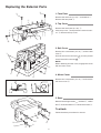
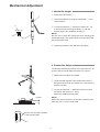
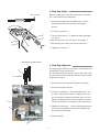
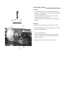
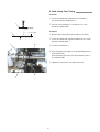
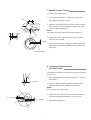
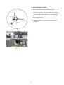
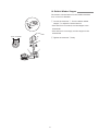
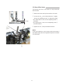
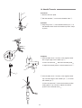
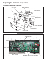
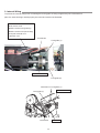
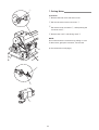
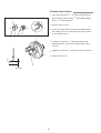
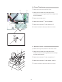
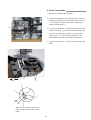
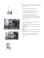
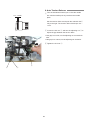
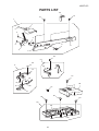
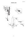
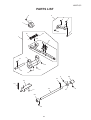
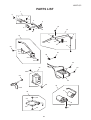
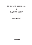
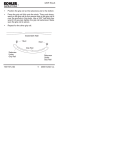
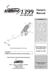
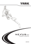
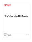
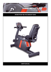
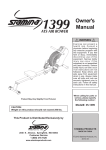
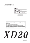
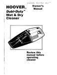
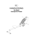
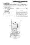
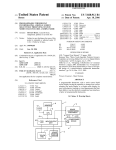
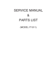
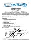
1600P-QC
SERVICE MANUAL
&
PARTS LIST
1600P-QC
1600P-QC
Table of Contents
Replacing the External parts
Face Plate ........................................................................................ 2
Top Cover ......................................................................................... 2
Belt Cover ......................................................................................... 2
Motor Cover ...................................................................................... 2
Base ................................................................................................. 2
Mechanical Adjustment
Needle Bar Height ............................................................................ 3
Presser Bar Height ........................................................................... 3
Feed Dog Height .............................................................................. 4
Feed Dog Alignment ......................................................................... 4
Feed Cam Timing ............................................................................. 5
Feed Lifting Cam Timing .................................................................. 6
Needle to Hook Timing ..................................................................... 7
Clearance Between Needle and Hook Point .................................... 7
Hook Stopper Position ...................................................................... 8
Bobbin Winder Stopper .................................................................... 9
Check Spring Stroke ........................................................................ 10
Pre-tension Dial ................................................................................ 10
Knee Lifter Lever .............................................................................. 11
Needle Threader ............................................................................... 12
Replacing the Electronic Components
Location of the Electronic Components ............................................ 13
Location of the Connectors .............................................................. 13
Internal Wiring .................................................................................. 14
Circuit Board-A ................................................................................. 15
Circuit Board-F and Slide Volume .................................................... 16
To Replace the Printed Circuit Board UD ......................................... 17
Driving Motor .................................................................................... 18-19
Needle Stop Position ........................................................................ 20
Power Transformer ........................................................................... 21
Machine Socket ................................................................................ 21
Light Bulb ......................................................................................... 22
Adjustment of the Thread Cutter Mechanism
Thread Cutter Blade ......................................................................... 23
Thread Guide Plate .......................................................................... 24
Static Cutter Blade ........................................................................... 25
Needle to Cutter Cam Timing ........................................................... 26
Thread Drawing Lever ...................................................................... 27
Auto Tension Release....................................................................... 28
Thread Cutter Troubleshooting ........................................................ 29
Parts list .............................................................................................. 30-51
1
1600P-QC
Replacing the External Parts
r
r
1. Face Plate
Remove the setscrew (4 x 10) q and washer w .
Remove the face plate e .
t
2. Top Cover
Remove the setscrews (4 x 25) r.
Lift the top cover t and pull out the motor connector y. Remove the top cover.
w
y
q
e
3. Belt Cover
Remove the 3 setscrews (4 x 12) u and the belt
cover i .
u
o
u
o
i
Pull out the socket connector 16 from the printed
circuit board UD connector 17 .
NOTE:
When attaching the belt cover, engage the hooks
with the motor cover.
4. Motor Cover
!0
Remove the 3 setscrews (4 x 12) o and remove
the motor cover !0 .
17
o
16
5. Base
Remove the 4 hinge screws !1 , washers !2 , rubber
feet !3 and base washers !4 . Remove the base !5 .
To attach:
Follow the above procedures in reverse.
!1
!5
!1
!4
!1
!1
!3
!2
2
Mechanical Adjustment
1. Needle Bar Height
z Remove the face plate.
w
x Turn the handwheel to bring the needle bar q to the
lowest position.
r
c Loosen the setscrew w . Move the needle bar q up
or down and match the upper hairline e with the
bottom edge of the needle bar bushing r .
NOTE:
Be sure not to rotate the needle bar when adjusting the
needle bar height. The needle clamp screw should be parallel to the upper shaft.
e
q
v Tighten the setscrew and attach the face plate.
2. Presser Bar Height
The distance between the bottom of the presser foot in up
position and the needle plate should be 5.7–6.3 mm.
z Remove the face plate and needle.
x Lower the feed dog below the needle plate. Place a
block 6 mm thick under the presser foot and lower the
presser foot lifter.
q
c Loosen the setscrew q . Raise the presser foot lifter
and tighten the setscrew q firmly.
Attach the needle and face plate.
NOTE:
Make sure that the presser foot should be parallel to the
feed dog slots w in the needle plate.
6.0mm
Presser foot should be parallel
to the feed dog slots.
w
3
3. Feed Dog Height
When the feed dog is fully raised the height should be
0.8–1.0 mm above the needle plate.
0.8 - 1.0mm
z Set the stitch length dial at 6 (Maximum). Turn the
handwheel to bring the feed dog to the highest
position.
w
x Loosen the setscrew q.
c Turn the eccentric pin w to adjust the feed dog height
to 0.9 mm.
• If the feed dog is too low, turn the pin to the right e .
• If the feed dog is too high, turn the pin to the left r .
e
q
v Tighten the setscrew q .
r
Lateral gaps should be even.
4. Feed Dog Alignment
The lateral gaps between both sides of feed dogs and
needle plate slots should be even.
The crealance between the front end of the center feed
dog and center slot should be 4.2–4.8 mm when the stitch
length dial is set at 0.
e
4.2 - 4.8 mm
z Remove the base and lay the machine on its back.
x Set the stitch length dial at 0.
c Loosen the setscrews q . Move the feed base w up
or down to adjust the clearance ebetween the front
end of the center feed dog and center slot to 4.5 mm.
Adjust the lateral position of the feed dogs by moving
the feed rock shaft r to the right or left if neccessary.
w
v Tighten the setscrewsq . Set the stitch length dial at 6
and turn the handwheel to check if the feed dogs do
not touch the needle plate.
r
b Attach the base.
q
4
5. Feed Cam Timing
To Check:
z Lower the needle bar by turning the handwheel until
the point of the needle is 17.5 mm above the upper sur
face of the needle plate q .
x The feed dogs should not move when moving the
reverse stitch lever up and down.
If the feed dogs move, adjust the feed cam timing as
follows.
q
17.5mm
To Adjust:
z Remove the base and lay the machine on its back.
A
w
x Lower the needle bar until the needle point is 17.5 mm
above the needle plate q .
c Loosen the setscrews w .
While moving the reverse stitch lever, turn the feed
cam e in the direction either A or B until the feed
dogs stop moving.
v Tighten the setscrews w and attach the base.
B
e
5
6. Feed Lifting Cam Timing
To check:
z Lower the needle bar until the point of needle is
0.4 mm below the needle plate q .
q
x The top of the feed dogs w should be 0–0.1 mm
above the needle plate.
0.4mm
w
q
To adjust:
z Remove the base and lay the machine on its back.
0 – 0.1mm
x Lower the needle bar until the needle point is 0.4 mm
below the needle plate q .
B
r
c Loosen the setscrew e .
v If the feed dogs are higher, turn the feed lifting cam r
in the direction A.
If the feed dogs are lower, turn the feed lifting cam r
in the direction B.
b Tighten the setscrew e and attach the base.
A
e
6
7. Needle to Hook Timing
z Remove the needle plate.
x Loosen the 3 setscrews q . Pull out the hook race
very slightly (less than 0.5 mm).
q
c Raise the needle bar from the lowest position until the
lower heirline w of the needle bar matches the edge
of the needle bar bushing e .
NOTE:
The needle bar rises 2 mm from the lowest position.
2.0mm
r
v Rotate the hook to match the hook point r with the
right side of the needle.
e
2.0mm
w
b Tighten the setscrews q slightly and proceed with the
adjustment of the clearance between the needle and
hook point.
Lowest position
8. Clearance Between Needle
and Hook Point
The clearance between the needle and hook point should
be 0–0.1 mm.
z Turn the handwheel to bring the hook point q behind
the needle w .
q
0 – 0.1mm
x Knock on the hook race rim lightly to make a slight
clearance between the needle and hook point.
NOTE:
Do not knock on the hook body.
q
c Tighten the setscrews firmly and check the needle to
hook timing and the thread path e (0.4–0.8 mm).
0 – 0.1mm
0.4 – 0.8mm
v Attach the needle plate.
w
e
7
9. Hook Stopper Position
z Remove the needle plate, base and feed dog.
x Loosen the setscrew q and move the hook stopper w
so that the center of the needle e is located between
the center of th hook stopper r and outer side of the
hook stopper spring t .
w
c Tighten the setscrew q and attach the needle plate
and base.
e
t
r
q
w
8
10. Bobbin Winder Stopper
The amount of thread wound on the bobbin should be
16.5–19.5 mm in diameter.
A
z Loosen the setscrew q . Turn the bobbin winder
stopper w to adjust the thread amount.
• If the amount is too mauch, turn the stopper in the
direction A.
• If the amount is not enough, turn the stopper in the
direction B.
B
16.5 –19.5mm
x Tighten the setscrew q firmly.
w
q
9
11. Check Spring Stroke
The amount of the needle thread supplied by the check
spring should be 11–15 mm.
z Thread the machine up to the thread guide q and
lower the presser foot.
Lower the needle bar to the lowest position.
q
A
B
x Hold the thread end and mark the point w on the
thread beside the thread guide.
NOTE:
There should be no slack in the thread.
r
e
w
c Pull the thread gently to the left until it stops (the
check spring e went full stroke).
v Measure the length of thread drawn out.
b Loosen the setscrew r and move the tension dial
guide t to adjust the stroke.
• If the length is too long, turn the guide in the direction A.
• If the length is too short, turn the guide in the direction B.
q
11–15 mm
w
n Tighten the setscrew r .
r
t
12. Pre-tension Dial
The standard position of the pre-tension dial is as follows:
q
4 mm
The screw head q sinks 4 mm below the dial face.
10
13. Knee Lifter Lever
The presser foot rises 7.5 mm when it is fully raised with
the knee lifter.
z Remove the base and lay the machine on its back.
x Loosen the nut q on the knee lifter lever w slightly
and turn the adjusting screw e to adjust the height.
• If it is lower than 7.5 mm, turn the adjusting screw e
clockwise.
• If it s higher than 7.5 mm, turn the adjusting screw e
counterclockwise.
7.5mm
q
w
c Tighten the nut q firmly and attach the base.
NOTE:
Lower the needle bar to the lowest position and check if
the needle cramp does not hit against the presser foot when
it is fully raised.
e
11
14. Needle Threader
w
To remove:
z Remove the face plate.
r
x Pull the threader q out from the threader shaft w .
To attach:
c Align the groove e of the theader with the pin r on
the threader shaft. Push the threader up until it snaps
in place.
q
e
To adjust:
z If the threader hook q thrusts or hits against either
left or right edge of the needle eye w :
Loosen the setscrew e . Move the threader plate r
to adjust the lateral position of the threader hook q .
e
r
w
x If the threader hook q thrusts or hits against either
top or bottom edge of the needle eye w , or misses
the needle eye w :
q
y
Loosen the setscrew t. Move the threader position
setting plate y up or down to adjust the vertical
position of the threader hook q .
t
12
Replacing the Electronic Components
1. Location of the Electronic Components
Bobbin winder motor
Slide volume
Bobbin winder switch
Circuit board A
Circuit board F
Upper shaft sensor
Driving motor
Lamp
Machine socket
Thread cutter switch
Capacitor
Push - pull solenoid
Power transfomer
Circuit board MS
2. Location of the Connectors
Thread cutter switch
Upper shaft sensor
Motor sensor
Circuit board-F
Power transformer
(primary)
Machine socket (primary)
Capacitor
Push-pull
solenoid
Bobbin winder
switch
Power transformer
(secondary)
Lamp
Arm lamp
Slide volume
13
Machine socket (secondary)
Driving motor
3. Internal Wiring
To prevent the internal wirings from contacting the moving parts or being caught in the joint of the external
parts, the internal wirings should properly be routed and secured as illustrated.
Motor cord
Motor sensor cord
Machine socket cord (primary)
Machine socket cord (secondary)
Push-pull solenoid cord
Capacitor cord
Cord binder
Cord guide (1)
Thread cutter cord
Cord guide (2)
Setscrews for cord guide (1)
Motor censor cord
Cord guide (1)
Cord binder
14
Motor cord
4. Circuit Board-A
To remove:
z Remove the top cover.
q
x Pull out connectors from the circuit board-A.
Remove the cords from the cord clips q .
w
c Remove the setscrews w and the board-A
case lid e .
v Pull out the connectors under the case lid.
Remove setscrews r and circuit board-A.
To attach:
Install the circuit board-A and secure it with
the setscrews r .
e
b Insert the following connectors:
t Machine socket (primary)
y Power transformer (primary)
u Driving motor
t
n Attach the board-A case lid e and secure it
with the setscrews w .
r
y
m Insert the remaining connectors and secure
the cords with the cord clips q on the case lid.
u
, Attach the top cover.
r
NOTE:
Do not disconnect the connectors by pulling on cord.
To disconnect, grasp the connector, not the cord.
Changing the Fuse
q
F1 Fuse
(AC250V 3.15A)
z Remove the Fuse from Fuse clip q with a screw
driver.
F2 Fuse
(AC250V 3.15A)
x Insert a new fuse and push it down into the fuse clip.
NOTE:
Replace the fuse with the same type and rating.
If there is any trace of burning, browning or other
abnormalities on the circuit board-A, replace it.
15
Fuse
Manufacture
Type
F1
SOC
ET-3.15A-250V
F2
SOC
ET-3.15A-250V
5. Circuit Board-F and Slide Volume
q
e
r
(A)
w
(B)
(A)
r
y
z
Removed the top cover.
x
Pull out the circuit board-F connector q, slide
volume connector w from the circuit board-A e .
c
Loosen the 3 set screw (A). Remove the
ornamental panel r .
t
u
16
v
Remove the 3 set screws (B) and remove the
b
n
circuit board-F t from the panel.
Remove the 2 CS-rings y and slide volume u .
To attach: follow the above procedure in reverse.
6.To Replace the Printed Circuit Board UD
Cord binder
To remove:
z Remove the top cover, belt cover and base.
x Remove the cord binder below the handwheel.
c Disconnect the connector of the thread cutter from the
printed circuit board A.
Remove the setscrew A and cord guide.
Printed circuit board A
Connector
Cord guide
v Remove the setscrew B and the thread cutter button
unit.
Replace the printed circuit board UD.
Setscrew A
To attach:
Follow the procedure above in reverse.
New printed circuit board UD
Setscrew B
Thread cutter button unit
17
q
7. Driving Motor
To remove:
z Remove the belt cover and motor cover.
x Pull out the motor sensor connector q .
c Pull out the motor connector w , while pushing the
connector lock e .
v Remove the nutsr and driving motor t .
NOTE:
Do not disconnect the connectors by pulling on cord.
To disconnect, grasp the connector, not the cord.
(to be continued on next page.)
w
r
e
w
t
18
8. Driving Motor (continued)
e
To attach:
z Install the driving motor q to the motor bracket w and
attach the motor belt e . Tighten the nuts r firmly.
u
x Loosen the setscrews t slightly and move the motor
up or down to adjust the motor belt tension.
The belt should deflect 4–5 mm when applying 300
grams of load to the middle of the belt.
Tighten the setscrews t firmly.
t
q
c Insert the motor connector y and motor sensor
connector u .
y
r
v Attach the motor cover and belt cover.
w
Motor belt tension
4 – 5mm
19
9.Needle Stop Position
z Turn the power switch q on while pressing the Up/
Down needle position button w and bobbin winding
button e at the same time.
u
x Remove the top cover.
w
e
c Lower the needle bar by turning the handwheel until
the needle point is 18.7 mm above the upper surface
of the needle plate r.
q
t
v Loosen the setscrew t . Rotate the upper shaft
shielding plate y toward you until the green LED u
turns on.
b Tighten the setscrew t and turn the power switch off.
n Attach the top cover.
r
y
18.7 mm
20
10. Power Transformer
z Remove the top cover and motor cover.
q
w
x Remove the board-A case lid and pull out the
transformer connectors (primary and secondary) from
the circuit board-A.
c Remove the driving motor.
v Remove the setscrew q and cord binder w .
r
b Remove the setscrews e and transformer r .
n To attach: follow the above procedure in reverse.
e
q
w
11. Machine Socket
z Remove the top cover, belt cover and motor cover.
q
w
x Remove the board-A case lid and pull out the
machine socket connectors (primary and secondary)
from the circuit board-A.
c Remove the setscrews q and cord guide (1) w .
v Remove the setscrews e and machine socket r .
b To attach: follow the above procedure in reverse.
e
r
21
12. Light Bulb
z Loosen the set screw q and remove the face plate w .
x Pull out the light bulb e from the lamp socket r .
c Insert a new bulb and push it into the lamp socket.
v Attach the face plate.
r
q
w
e
22
Adjustment of the Thread Cutter Mechanism
1. Thread Cutter Blade
u
q
To replace:
z Remove the needle plate and base.
x Remove the static cutter blade. Remove the hinge
screw qand thread cutter balde w.
c Attach the new thread cutter balde and secure it with
the hinge screw q.
w
2 – 2.5 mm
Attach the static cutter blade and adjust the position of
the static cutter balde and thread cutter blade.
e
To adjust:
z Remove the needle plate and base.
x Lower the needle bar to the lowest position. Turn the
handwheel toward you while pushing up the link body
e to engage the thread cutter blade wand bring it
to the end of the stroke.
t
c Loosen the nut rand move the thread cutter link t
to the left or right to adjust the position of the thread
cutter blade. The point y of the thread cutter blade
should be 2–2.5 mm from the center of the needle
drop position u.
r
u
v Tighten the nut r. Attach the needle plate and
base.
o
y
2 – 2.5 mm
i
NOTE:
Check if there is apploximately 5 mm distance between the
tail of the hook wing i and the end point o of the thread
cutter blade when the end point oof the thread cutter blade
is aligned with the center of thr needle drop position u.
Apploximately 5 mm
o
23
2. Thread Guide Plate
z Remove the needle plate.
x Loosen the flat screw q and adjust the position of the
thread guide plate w .
t
c The left inner edge e of the thread guide plate should
be approximately 1.4 mm from the center of the
needle drop position r and the back inner edge t
of the thread guide plate should be approximately
2.7 mm from the center of the needle drop position
r.
2.7 mm
r
v Tighten the flat screw firmly. Attach the needle plate.
e
1.4 mm
w
q
24
3. Static Cutter Blade
z Remove the needle plate and base.
x Lower the needle bar to the lowest position. Turn the
handwheel toward you while pushing up the link body
q to engage the thread cutter blade w and bring it
under the static blade e .
q
c Loosen the setscrews r and adjust the position of the
static cutter blade e so that the distance between the
center of the needle drop position t and the static
cutter blade e is 4 mm and the left edges of the
static blade and thread cutter blade are aligned.
v Tighten the setscrews r . Attach the needle plate and
base.
e
r
4 mm
t
w
e
4 mm
Align the left edges of the thread
cutter blade and the static cutter
blade.
25
4. Needle to Cutter Cam Timing
z Remove the base.
x Pemove the setscrews q and gear cover w .
c Lower the needle bar to the lowest position.
Turn the handwheel toward you to raise the needle
bar while pusging up the link body e .
t
10.5 mm
v Continue to turn the handwheel until the thread
drawing arm r starts to move to the right.
The needle point should be 10.5 mm above the upper
surface of the needle plate t when the thread drawing
arm starts to move.
w
b Loosen the setscrews y and turn the hook shaft
gear u to adjust the timing.
q
• If the needle point is too high, turn the hook shaft gear
in the direction A.
• If the needle point is too low, turn the hook shaft gear in
the direction B.
NOTES:
Hold the hook so that it will not rotate when turning the
hook shaft gear.
Check the needle to hook timing and adjust it if neccessary.
e
r
n Tighten the setscrews y firmly. Attach the gear
cover w and secure it with the setscrews q .
Attach the base.
u
y
B
u
A
26
5. Thread Drawing Lever
z Remove the base.
x Loosen the setscrew q and free the stopper w .
c Turn the the handwheel toward you to raise the
needle bar from the lowest position until the needle
point is 10.5 mm above the upper surface of the needle
plate.
w
v Push the solenoid disk e fully to swing the thread
drawing lever r .
Loosen the setscrew t and move the thread drawing
arm y to the left or right so that the tip of the thread
drawing lever r lightly contacts with the bobbin.
b Tighten the setscrew t .
n Restore the stopper w and press it against the thread
drawing lever r , while pushing the solenoid diske .
Tighten the setscrew q firmly.
q
y
m Attach the base.
t
r
e
27
6. Auto Tension Release
z Turn the handwheel toward you to raise the needle
bar until the needle point is just above the needle
plate.
0.5 - 1.0mm
Set the tension dial at 4 and push the solenoid disk q
fully to the right. The tension disks should open 0.5 –
1 mm.
c Loosen the lock nut w and turn the adjusting nut e to
adjust the gap between the tension disks.
• If the gap is too wide, tun the adjusting nut counterclock
wise.
• If the gap is too narrow, tun the adjusting nut clockwise.
v Tighten the lock nut w .
q
e
w
28
Thread Cutter Troubleshooting
The needle thread is not cut. The static cutter is dull.
Replace or grind the static cutter blade.
The static cutter blade is out Adjust the position of the static cutter blade (see page 25).
of position.
Skipped stitch before thread Reduce the check spring stroke (see page 10).
cutting.
Adjust the needle to hook timing (see page 7).
The bobbin thread is not cut. The thread cutter blade is out Adjust the stroke of the thread cutter blade (see page 23).
of position.
The thread guide plate is out Adjust the position of the thread guide plate (see page 24).
of position.
The thread slips out the The needle to cutter cam tim- Adjust the needle to cutter cam timing (see page 26).
needle eye when starting ing is too late.
sewing.
The thread drawing lever is Adjust the thread drawing lever position (see page 27).
out of position.
The needle thread bunches A too long tail of the needle Adjust the needle to cutter cam timing (see page 26).
up on the wrong side of the thread is left after thread cut- Adjust the position of the static cutter blade (see page 25).
fabric at the beginning of the ting.
seam.
The tail of the needle thread The pre-tension is too loose. Tighten the pre-tension.
appears on the right side of
the fabric.
The needle to cutter cam tim- Adjust the needle to cutter cam timing (see page 26).
ing is too late.
The static cutter blade is out Adjust the position of the static cutter blade (see page 25).
of position.
Skipped stitches at the begin- The auto tension release is Adjust the auto tension release (see page 28).
ning of the seam due to a too not enough.
short tail of the thread after
thread cutting.
The needle to cutter cam tim- Adjust the needle to cutter cam timing (see page 26).
ing is too early.
The thread drawing lever is Adjust the thread drawing lever position (see page 27).
outt of position.
The static cutter blade is out Adjust the static cutter blade position (see page 25).
of position.
29
1600P-QC
PARTS LIST
1
26
26
3
4
8
5
10
4
25
6
2
16
48
14 15
21
9
7
11
13
5
20
12
18
49
22
17
23
24
19
18
52
27
37
28
36
30
45
31
45
35
50
44
39
51
45
38
29
53
41
34
45
42
33
40
43
46
47
32
18
30
1600P-QC
PARTS LIST
KEY
NO.
PARTS
NO.
1
2
3
4
5
6
7
8
9
10
11
12
13
14
15
16
17
18
19
20
21
22
23
24
25
26
27
767603605
767007201
846015004
846016005
000115205
767008109
000015101
767639002
000160102
846021003
767514608
000111201
767604008
846514101
000115308
000104119
846179007
000081005
000101703
000014007
000188405
767152006
763033204
000101404
767211004
000080901
767602202
767602604
767005209
767006107
767197003
000103004
840602109
000095105
767208008
000071024
000103510
767611101
767016203
767038005
767174004
501509703
000114905
767183006
000001104
000103808
767146007
000026002
000071013
846227001
767696007
767224000
000053008
100517008
28
29
30
31
32
33
34
35
36
37
38
39
40
41
42
43
44
45
46
47
48
49
50
51
52
53
DESCRIPTION
Top cover (unit)
Top cover
Handle
Pin
Setscrew 4x6
Foot pressure adjusting dial
Snap ring CS-22
Thread guide (unit)
Adjustable lock nut
Top cover thread guide
Pre-tension (unit)
Hexagonal socket screw 4x4
Bobbin winder (unit)
Micro switch
TP screw 2x8
Setscrew 4x20
Motor cover
Setscrew 4x8
Setscrew 4x12
Snap ring CS-4
Cord binder 2
Oil wick fixing plate
Oil wick
Setscrew 4x6
Felt
Setscrew 4x25
Face plate (unit) (U.S.A.) (Australia) (UK) (Continental Europe)
Face plate (unit) (Canada)
Face plate
Foot pressure display window
Presser bar base
Setscrew 3.5x6
Thread cutter (unit)
Setscrew 3x5
Needle sticker
Washer 4
Setscrew 4x10
Front bracket (unit)
Front bracket
Lamp bracket
Lamp cushion
Lamp socket (unit)
Setscrew TP 2x10
Lamp set plate
Snap ring E-2.3
Setscrew 3x5
Lamp shield plate
Wedge base lamp 12V 5W
Washer
Handle spring
Presser foot lifter switch (unit)
Set plate
Cord binder
Sticker (Canada)
31
1600P-QC
PARTS LIST
9
1
6
10
5
4
8
2
11
16
13
15
8
33
12
34
14
3
7
31
8
17
18
19
24
23
22
20
25
21
32
28
26
32
27
30
29
1600P-QC
PARTS LIST
KEY
NO.
PARTS
NO.
1
2
3
4
5
6
7
8
9
10
11
767605504
767011116
767014304
767636009
784177000
767015006
000115700
000170507
767010001
000101806
767653002
767665007
014390106
023690211
767507000
767134002
000103808
000062402
767135003
000115504
767606907
767606918
767606206
767012209
767013004
767188001
000171302
767187000
000101404
767643102
797363005
785260004
784169010
000070300
000053008
830312016
100045000
767541006
000071024
12
13
14
15
16
17
18
19
20
21
22
23
24
25
26
27
28
29
30
31
32
33
34
DESCRIPTION
Belt cover (unit)
Belt cover
Stitch length window
Thread guide (unit)
Thread guide post
Thread guide bar
Setscrew TP 4x10
Setscrew 4x12
Motor cover
Setscrew 4x16
Motor (unit) 120V (U.S.A.) (Canada)
Motor (unit) 230V (Australia) (UK) (Continental Europe)
Motor (unit) (U.S.A.) (Canada)
Motor (unit) (Australia) (UK) (Continental Europe)
Printed circuit board V (unit)
Set plate
Setscrew 3x5
Nut 4-2-7 (U.S.A.) (Canada)
Motor bracket
Setscrew TP 5x10
Base (unit) (U.S.A.)
Base (unit) (Canada)
Base (unit) (Australia) (UK) (Continental Europe)
Base
Base cover
Table latch spring (2)
Setscrew 4x8 (B)
Table latch spring (1)
Setscrew 4x6
Bed rubber foot (unit)
Bed rubber foot
Bed rubber foot plate
Bed rubber foot screw
Washer
Cord binder
Sticker (U.S.A.)
Sticker (Canada)
Jack cord (unit)
Washer 4
33
1600P-QC
PARTS LIST
30
10
10
1
7
9
5
3
5
6
8
4
2
24
21
20
11
22
23
14
12
17
13
19
27
18
26
16
31
15
20
20
20
25
28
29
34
1600P-QC
PARTS LIST
KEY
NO.
PARTS
NO.
1
2
3
4
5
6
7
8
9
10
11
12
13
14
15
16
17
18
19
20
21
22
23
24
25
767601142
767003908
767004600
767501004
000120203
767140207
767516002
767354000
000014306
000115205
767626006
767126001
000101127
767127002
767128003
501509806
000225209
000053008
000026002
000081005
767612009
767153007
763033020
000101404
767627708
767627801
767130008
000075109
767532107
767536101
26
27
28
29
30
31
767129004
767285009
000053101
DESCRIPTION
Ornamental plate (unit)
Ornamental plate
Button 1
Printed circuit board F (unit)
Setscrew 3x8
Speed control slider
Slide volume
Emblem
Snap ring CS-3
Setscrew TP 4x6
Arm lamp (unit)
Reflector plate
Setscrew 3x4
Arm lamp set plate
Lamp holder
Lamp socket (unit)
Setscrew 2.3x12 (B)
Cord binder
Wedge base lamp 12V 5W
Setscrew 4x8
Oil wick fixing plate (2) (unit)
Oil wick fixing plate
Oil wick
Setscrew 4x6
Printed circuit board A (unit) (U.S.A.) (Canada)
Printed circuit board A (unit) (Australia) (UK) (Continental Europe)
Printed circuit board A case (upper)
Setscrew 3x12-2V
Printed circuit board A (unit) 120V (U.S.A.) (Canada)
Printed citcuit board A (unit) 230V (Australia) (UK)
(Continental Europe)
Printed circuit board A case (lower)
Cord guide (2)
Cord binder
35
1600P-QC
PARTS LIST
1
4
13
3
14
15
31
12
33
7
11
2
32
5
10
8
9
6
24
22
17
16
21
20
25
35
19
34
26
18
19
22
28
29
27
30
36
23
36
1600P-QC
PARTS LIST
KEY
NO.
PARTS
NO.
1
2
3
4
5
6
7
8
9
10
11
12
13
14
15
16
767669001
767026103
767303004
000103808
767027001
000111304
767222008
000036201
767225001
767028002
767029003
767030100
767031008
767173003
767172002
762505003
704511105
763048109
767039006
000101404
767041001
767042002
000111201
767091006
767641030
767165013
767515001
767209009
767210003
767169006
767401047
767502108
000114710
000111108
767054007
000081119
767056009
17
18
19
20
21
22
23
24
25
26
27
28
29
30
31
32
33
34
35
36
DESCRIPTION
Presser bar lifter (unit)
Presser bar lifter
Presser foot sensor plate
Setscrew 3x5
Presser bar bracket
Hexagonal socket screw 5x5
Spring
Washer FT-80
Spring
Presser bar
Presser bar spring
Presser foot pressure indicator
Presser foot pressure adjusting screw
Spacer
Presser foot support spring
Presser foot (unit) (U.S.A.) (Canada) (Australia)
Presser foot (unit) (UK) (Continental Europe)
Setscrew
Arm thread guide (lower)
Setscrew 4x6
Needle bar bushing (upper)
Felt
Hexagonal socket screw 4x4
Needle bar bushing (lower)
Needle bar (unit)
Needle bar
Needle clamp (unit)
Needle bar thread guide
Setscrew
Needle guard
Needle HLx5–14
Thread tension (unit)
Setscrew TP 3x6
Hexagonal socket screw 4x6
Arm thread guide
Setscrew
Thread guide
37
1600P-QC
PARTS LIST
12
13
8
1
14
2
7
6
11
3
27
5
4
4
10
16
9
15
17
18
28
21
26
28
24
23
20
19
22
16
38
25
1600P-QC
PARTS LIST
KEY
NO.
PARTS
NO.
1
2
3
4
5
6
7
8
9
10
11
12
13
14
15
16
17
18
19
20
21
22
23
24
25
26
27
28
767609106
767018009
767019000
820374004
767020004
767220006
767281108
102053007
767017008
767021005
681009101
767171001
846033008
767650009
767233002
000081005
767651103
000001609
767530002
846210001
000002105
767290007
767232001
000036500
767231000
676222008
761045007
000101404
DESCRIPTION
Hook cover plate (unit)
Hook cover plate
Hook cover plate spring
Setscrew 2x2.3
Hook cover plate supporter spring
Sticker
Needle plate
Setscrew
Hook cover plate retainer
Attachment mount
Setscrew
Presser foot lifter
Hinge screw
Thread tension release lever (unit)
Plate
Setscrew 4x8
Thread tension release base plate (unit)
Snap ring E-5
Wire (unit)
Roller
Snap ring E-3
Spring
Thread tension release base plate
Washer FT-60
Thread tension release crank
Spring
Thread tension release lever spring
Setscrew 4x6
39
1600P-QC
PARTS LIST
22
24
18
13
5
54
21
14
12
15
17
17
20
23
19
16
22
37
25
26
28
44
32
27
36
34
30
33
29
5
35
31
57
3
58
6
5
8
7
2
37
1
4
56
45
50
47
42
55
38
51
39
41
56
49
9
10
46
11
52
40
48
43
53
40
1600P-QC
PARTS LIST
KEY
NO.
PARTS
NO.
1
2
3
4
5
6
7
8
9
10
11
12
13
14
15
16
17
18
19
20
21
22
23
24
25
26
27
28
29
30
31
32
33
34
35
36
37
38
39
40
41
42
43
44
45
46
47
48
49
50
51
52
53
54
55
56
57
58
767271002
820102009
000103509
767195012
000111304
767139100
556047007
618070004
767618005
000002806
000115504
767697008
767617004
767065001
000028107
761102003
767304005
767227003
767077006
767178008
000032702
000115205
767070009
000110107
767682000
767503006
761088002
761089003
650040005
650041006
767073013
761086000
647139002
767072001
763033400
761091008
000111201
767624004
767118309
767124124
767115100
000081005
000001609
767136004
767632005
767034001
767032009
000004808
767033000
000125208
000125404
000002105
767633006
767071000
767168005
000103808
767634007
767043003
DESCRIPTION
Upper shaft shield plate
Washer
Setscrew 4x10
Belt wheel
Hexagonal socket screw 5x5
Handwheel
Washer
Setscrew
Idler (unit)
Snap ring E-6
Setscrew TP 5x10
Upper shaft (unit)
Upper shaft (unit)
Take up lever crank
Spring pin 4x25
Setscrew
Ball bearing
Spacer
Ring
Ball bearing (6901ZZ)
Snap ring crescent (5103-46)
Setscrew TP 4x6
Upper shaft timing gear
Hexagonal socket screw WP 5x5
Take up lever (unit)
Take up lever (unit)
Take up lever
Take up lever supporter
Felt
Felt holder
Needle bar conn. stud
Needle bar crank pin
Setscrew
Needle bar crank rod
Oil wick
Take up lever pin
Hexagonal socket screw 4x4
Feed adjusting base (unit)
Indicator drum
Reverse stitch lever
Stitch length dial
Setscrew 4x8
Snap ring E-5
Timing belt
Needle threader (unit)
Needle threader plate
Needle threader shaft
Spring pin 2x6
Needle threader spring
Pin E 2x10 – CH
Pin G 2x14 – CH
Snap ring E-3
Needle threader guard plate (unit)
Timing belt
Needle threader guide plate
Setscrew 3x5
Needle threader positioning base (unit)
Needle threader positioning base
41
1600P-QC
PARTS LIST
1
3
2
27
28
29
31
35
8
30
8
33
7
36
6
37
34
32
4
38
8
8
5
9
10
8
10
11
18
10
13
16
10
14
19
19
16
17
15
12
16
26
25
20
21
23
22
11
21
13
13
11
24
13
42
1600P-QC
PARTS LIST
KEY
NO.
PARTS
NO.
1
2
3
4
5
6
7
8
9
10
11
12
13
14
15
16
17
18
19
20
21
22
23
24
25
26
27
28
29
30
31
32
33
34
35
36
37
38
767510101
767510006
761094115
767518004
767079008
767201001
000169709
000081005
767698102
000111201
000115205
767081003
000111304
767241003
000114606
820166001
767182005
767084006
000101404
767085007
767067003
767644000
000110107
767221007
767613000
000114802
767657006
767264002
767266004
000001609
767658007
767268006
767280004
000002105
767251006
767259004
000002507
767276007
DESCRIPTION
Hook race (unit)
Bobbin case (unit)
Bobbin
Hook race stopper (unit)
Hook race stopper
Hook race stopper spring
Setscrew 2x2.3
Setscrew 4x8
Hook race shaft (unit)
Hexagonal socket screw 4x4
Setscrew TP 4x6
Hook race gear
Hexagonal socket screw 5x5
Thread cutter cam
Setscrew TP 3x14
Lower shaft ring
Ball bearing (698Z)
Gear cover
Setscrew 4x6
Lower shaft bushing
Felt
Lower shaft (unit)
Hexagonal socket screw WP 5x5
Lower shaft gear
Lower shaft supporter (unit)
Setscrew TP 4x12
Auto-thread cutter (unit)
Thread cutter blade
Thread guide plate
Snap ring E-5
Thread drawing lever (unit)
Thread drawing lever
Spring
Snap ring E-3
Link
Cushion 3
Snap ring E-4
Spring
43
1600P-QC
PARTS LIST
2
3
5
4
1
2
12
6
12
7
13
8
9
11
14
2
14
10
2
22
2
19
16
15
18
17
20
2
44
21
2
1600P-QC
PARTS LIST
KEY
NO.
PARTS
NO.
1
2
3
4
5
6
7
8
9
10
11
12
13
14
15
16
17
18
19
20
21
22
767089001
000111304
767620000
000002909
000002507
000114802
767619109
767621104
767094009
767095000
000001609
822063003
767212005
000111201
767120005
767121006
000101404
767096001
000030205
767097002
639095000
767099004
DESCRIPTION
Feed lifting cam
Hexagonal socket screw 5x5
Feed link (unit)
Snap ring E-7
Snap ring E-4
Setscrew TP 4x12
Feed base (unit) (1)
Feed base (unit) (2)
Feed rock arm
Feed rock arm pin
Snap ring E-5
Felt (2)
Felt holder sping
Hexagonal socket screw 4x4
Feed base spring
Spring attach plate
Setscrew 4x6
Feed rock shaft
Snap ring E-8
Bushing (Front)
Ring
Bushing (Rear)
45
1600P-QC
PARTS LIST
1
48
10
52
49
51
11
8
6
50
19
8
7
6
5
8
8
2
8
8
4
5
8
12
9
14
3
18
8
17
16
13
43
40
42
41
15
47
44
21
5
8
20
45
32
5
36
35
26
5
46
39
33
27
28
22
47
25
27
38
37
31
34
5
24
5
29
25
5
23
30
53
55
57
58
54
57
56
43
47
46
46
1600P-QC
PARTS LIST
KEY
NO.
PARTS
NO.
1
2
3
4
5
6
7
8
9
10
11
12
13
14
15
16
17
18
19
20
21
22
23
24
25
26
27
28
29
30
31
32
33
34
35
36
37
38
39
40
41
42
43
44
45
46
47
48
49
50
51
52
53
54
55
56
57
58
767663005
767100009
000218106
767101000
000001609
767102001
767106005
000111304
767157001
767664006
767107006
767159003
767108007
767099004
767097002
639095000
767111003
639095103
767112004
767654003
767242004
767244006
767243005
767253008
000002507
767247005
000036108
767245007
767252007
000101404
767275006
767282006
000103004
767246008
767247009
767248000
000061102
000070506
767289003
767656005
767249001
767250005
000061319
000102003
767238007
000061412
000081005
767661405
767283306
767284008
767542007
000161701
767655200
767534109
767254009
000070300
000115504
767235004
DESCRIPTION
Feed regulator (unit)
Feed adjusting arm
Bolt 5x16
Pin
Snap ring E-5
Feed link
Pin
Hexagonal socket screw 5x5
Washer
Feed cam (unit)
Feed adjusting arm
Pin
Feed adjusting shaft
Bushing (rear)
Bushing (front)
Lower shaft ring
Feed regulator spring
Lower shaft ring
Feed adjusting arm
Thread cutter driving base (unit)
Driving arm base plate
Driving arm
Link
Driving arm pin
Snap ring E-4
Cam spring
Washer FT-70
Driving lever
Thread drawing arm
Setscrew 4x6
Spring
Guard plate
Setscrew 3.5x6
Thread tension release arm
Thread cutter link
Hinge screw (3)
Nut 4-1-7
Washer 4
Limitter plate
Link (unit)
Link
Coupling
Nut 5-1-8
Setscrew 5x10
Wire joint
Nut 5-3-8
Setscrew 4x8
Thread cutter button (unit)
Button (2)
Button holder
Printed circuit board UD (unit)
Setscrew 2.3x5 (B)
Solenoid (unit)
Push-pull solenoid (unit)
Set plate
Washer 5
Setscrew TP 5x10
Plate (2)
47
1600P-QC
PARTS LIST
1
6
3
2
4
9
9
18
5
11
12
8
7
10
9
19
17
8
14
13
16
15
23
25
21
26
22
20
25
25
27
28
28
24
28
30
29
31
33
34
36
32
35
25
36
48
1600P-QC
PARTS LIST
KEY
NO.
PARTS
NO.
1
2
3
4
5
6
7
8
9
10
11
12
13
14
15
16
17
18
19
20
21
22
23
24
767642008
767057000
000196107
000061412
767058001
000030009
767352008
767060006
000001609
000111201
767059002
767616003
767062008
846173001
767063009
000013800
846171009
000115700
767631004
000103808
767131009
843505409
000066705
767533005
767537009
000081005
000188601
767660002
767666008
000103509
767237006
767659008
767535007
767279000
767667009
767538000
767277008
000103808
25
26
27
28
29
30
31
32
33
34
35
36
DESCRIPTION
Knee lifter lever (1) (unit)
Knee lifter lever (1)
Hexagonal socket screw 5x20 (Ball point)
Nut
Knee lifter shaft
Snap ring E-10
Stopper
Knee lifter lever (2)
Snap ring E-5
Hexagonal socket screw 4x4
Shaft
Knee lifter lever (3) (unit)
Knee lifter lever shaft
Knee lifter lever spring
Presser foot lifter rod
Snap ring CS-6
Knee lifter lever (unit)
Setscrew TP 4x10
Upper shaft sensor (unit)
Setscrew 3x5
Sensor fixing plate
Printed circuit board P (unit)
Setscrew 3x8
Transformer (unit) 120V (U.S.A.) (Canada)
Transformer (unit) 230V (Australia) (UK) (Continental Europe)
Setscrew 4x8
Cord binder
Machine socket (unit) (U.S.A.) (Canada)
Machine socket (unit) (Australia) (UK) (Continental Europe)
Setscrew 4x10
Cord binder (1)
Capacitor (unit)
Capacitor
Capacitor case
Noise filter (unit) (Australia) (UK) (Continental Europe)
Noise filter (unit)
Noise filter set plate
Setscrew 3x5
49
1600P-QC
PARTS LIST
1
2
3
4
5
6
10
7
8
11
9
12
13
15
14
16
(U.S.A.) (Canada)
(Australia)
17
18
(UK)
50
(Continental Europe)
1600P-QC
PARTS LIST
KEY
NO.
PARTS
NO.
1
2
3
4
5
6
7
8
9
10
11
12
13
14
15
16
820832005
647803004
761094115
200100801
825252000
761172004
822020503
784223105
624806006
767802008
802424004
846417000
762456204
366401400
043670206
653524007
830314018
830377008
830335004
767800279
767800327
767805001
17
18
DESCRIPTION
Large screwdriver
Small screwdriver
Bobbin
Cloth guide
Thumb screw
Hemmer foot
Spool cap
Spool holder
Net
Assorted needle set
Lint brush
Knee lifter (unit)
Oil
Accessory box
Foot control
Power supply cord (U.S.A.) (Canada)
Power supply cord (Australia)
Power supply cord (UK)
Power supply cord (Continental Europe)
Instruction book (English/Spanish/French)
Instruction book (Swedish/Norwegian/Danish)
Cover
51