1
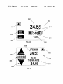
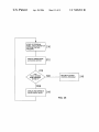
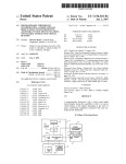
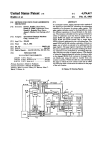
US007028912B1
(12) United States Patent
(54)
(10) Patent N0.:
(45) Date of Patent:
PROGRAMMABLE THERMOSTAT
INCORPORATING A DISPLAY SCREEN
SELECTIVELY PRESENTING SYSTEM
MODES THAT INCLUDES A SIMPLE MODE
(76)
Howard R0sen, Lyncroft Road,
Hampstead, Quebec (CA) H3X 3E3
Subject to any disclaimer, the term of this
patent is extended or adjusted under 35
1 0/878,825
(22)
Jun. 28, 2004
Apr. 18, 2006
6,285,912 B1
6,330,806 B1
9/2001 Ellison
12/2001 Beaverson
6,344,861 B1
2/2002 Naughton
6,478,233
6,595,430
6,621,507
2004/0245352
2004/0262410
2005/0154496
2005/0194457
B1
11/2002 Shah
B1
7/2003 Shah
B1
9/2003
A1* 12/2004
A1* 12/2004
A1* 7/2005
A1* 9/2005
FOREIGN PATENT DOCUMENTS
U.S.C. 154(b) by 82 days.
(21)
US 7,028,912 B1
DE
EP
W0
W0
3334117
0985994
WO 97/11448
WO 97/39392
4/1985
3/2000
3/1997
10/1997
Related US. Application Data
OTHER PUBLICATIONS
(63) Continuation-in-part of application No. 10/654,235,
?led on Sep. 3, 2003.
ADI, “Leopard User Manual,” 93 pages, 2001.
Business Wire, “Micro Touch Specialty Products Group to
Capitalize on Growing Market for LoW-Cost Digital Matrix
(52)
US. Cl.
(58)
Field of Classi?cation Search .............. ..
DeKoven et al., “Designing Collaboration in Consumer
Products,” 2 pages, 2001. Freudenthal et al., “Communicat
ing extensive smart home functionality to users of all ages:
the design of a mixed-initiative multimodal thermostat
interface,” pp. 34-39, Mar. 12-13, 2001.
Touchscreens,” p1174 (2 pages), Jan. 6, 1999.
(51)
...................... ..
236/1 C; 236/94; 345/173;
700/276
236/1 C,
236/94; 345/173; 62/126,129; 165/111;
700/276
See application ?le for complete search history.
(56)
(Continued)
Primary ExamineriMarc Norman
(57)
References Cited
ABSTRACT
A programmable thermostat, With a touch screen liquid
U.S. PATENT DOCUMENTS
crystal display having the capability to change from a more
complex ?rst mode display to a simple mode display for
users With adaptive, learning or visual impairments that limit
9/1980
4/1989
2/1992
12/1992
10/1998
5/2000
2/2001
their ability to use the relatively complicated user interfaces
of prior art programmable thermostats.
16 Claims, 11 Drawing Sheets
MEMORY
/8
/
1
f9
/
SPACE
CONDITIONING
EQUIPMENT
CPU
6
\III Y\|I|
5‘
INPUT/OUTPUT
UNIT
S
CONDITIONED
SPACE
41
11
f
LIQUID
/
TOUCH
CRYSTAL
DISPLAY
12)
3
US 7,028,912 B1
Page 2
OTHER PUBLICATIONS
Honeywell News Release, “HoneyWell’s NeW Sysnet Facili
ties Integration System For Boiler Plant and Combustion
Safety Processes,” 4 pages, Dec. 15, 1995.
HoneyWell, “W7006A Home Controller GateWay User
Guide,” 31 pages, Jul. 2001.
“High-tech options take hold in neW homesi200-08
28iDallas Business Journal,” http://biZiournals.com!dal
las/stories/2000/08/28/focus4, 3 pages, dated Aug. 28, 2000,
printed Aug. 19, 2004.
“Product ReVieWiPhilips Pronto Remote Control,” http://
hometheaterhi?com/Volume
62/
philipsprontoremotecontrol.html, 5 pages, dated May 1999,
printed Aug. 20, 2004.
http://WWW.cc.gatech.edu/computing/classes/cs675l 94 fall/
2roupc/climate-2/node l .html, “Contents,” 53 pages,
printed Sep. 20, 2004.
“HAI Company Background,” http://WWW.homeauto.com/
AboutHAI/abouthai main.htm, 2 pages, printed Aug. 19,
2004.
Cardio Manual, available at http://WWW.secant.ca/En/
Documentation/Cardio2é-Manual.pd?
Cardio
Home
Automation Inc., 55 pages, printed Sep. 28, 2004.
“RC X10 Automation Forum: Control your Heating and
Cooling
System
With
Pronto(l/ 1),”
http://WWW.
remotecentral.comlcgi-binlmboardlrc-X l 0/thread.c~i? l2,
2 pages, dated Apr. 23, 1999, printed Aug. 20, 2004.
* cited by examiner
U.S. Patent
Apr. 18, 2006
Sheet 1 0f 11
/8
1h
/
US 7,028,912 B1
1
3
MEMORY
CLOCK
/
['9
SPACE
CONDITIONING
EQUIPMENT
CPU
6\
10\
27k
%
5‘
INPUT/OUTPUT
UNIT
LIQUID
/
h8 SPACE
1
f2
FIG. 1A
CRYSTAL
TSXSH /
1
CONDITIONED
4
K11
7\
1
DISPLAY
12)
104
103
///
\\
FIG. 1
100
109
101
102
U.S. Patent
Apr. 18, 2006
Sheet 2 0f 11
US 7,028,912 B1
107
107
108
FIG. 3
111
110
\nnnn
r'lnnn)
U.S. Patent
Apr. 18, 2006
US 7,028,912 B1
Sheet 3 0f11
116
/139
/oc
24.5
117
#525253
/
118
‘223w
‘
\
F|G.6
120
121
119
F|G.7
122
/
124 116
\ PROG
AUTO
123
_%
183
24 5°
JV»
I
COOL
24.0
//m / HEAT 11.5
// \ \
125
126
127
128 129
U.S. Patent
Apr. 18, 2006
Sheet 4 0f 11
US 7,028,912 B1
122
132
\
FIG. 8
RUN
\
PROG
m
o
w 24.5c
m 021: 50::
137
122
/
\
RUN
m
138
/
TOUCHWINDOW
T0 CONFIRM
FIG. 9
COOL
m
24.0
HEAT : 21.5 n
122\
RUN
F|G.10
116
\
m
/m
24 . 5°C
CO0L24.0
118//60/24/o3
4:03PM
121
U.S. Patent
Apr. 18, 2006
140
1
41/
/
142
143
144
Sheet 5 0f 11
US 7,028,912 B1
FIG. 11
149
DATEITIME
SETTINGS
ADVANCED
II/148
SETTINGS
PROGRAM
VACATION
SETTINGS
SETTINGS
ENERGY
WATCH
FILTER
II
I
MONITOR
CLEAN
SCREEN
/
150
INSTALLER
ENERGY
151// WATCH
152/
153/
"
SECURITY
!
- -
¢ -
156
SETTINGS
157
DEAD
BAND
1 58
FURNACE
I
.
MESSAGE
OFF
154/
A
J
170
164
/
ELECTRIC
159 \
FURNACE
EIVIER. ELECT.
AIR
CONDITIONER
NO
COMPRESSOR
HG 12
FURNACE
GAS
FURNACE
OIL
FURNACE
FURNACE
OFF
169
U.S. Patent
Apr. 18, 2006
US 7,028,912 B1
Sheet 6 0f 11
\
E; m COMPRESSOR KW
/
174 /
175 //m
171
[Kw
FIG. 13
177
5
LAST 30 DAYS
/ 2o
178/
55
176
KWH COMP /
KWH FURN.
179 // 5
KWH FAN
// so
180 / COST
KWH TOTAL
120.53
181 /
FIG. 14
\
182
U.S. Patent
Apr. 18, 2006
fLlUT-JLJU
/
/
Sheet 7 0f 11
US 7,028,912 B1
113
ULIULIU‘
/
111
I
24.51:)
L
'
HEATH}
113A
‘Ell-Inn
rlnnn 4
f
I
/ \
I]
FIG. 15
C
:r?/E
3
D:l
E
C
/
24 . 5°C
HEATILS
06I24I03
I
:l
FIG. 16
PROG
J
9385311
110%
E
E
:I
I
I:
C
k
FULILILILI
/
111
/
155
UULVLILI\
/
I
INSTALLER
MESSAGE
ENERGY
SECURITY’
WATCH
SETTINGS
DEAD
1
m
NO
COMPRESSOR
155A
FURNACE
OFF
3
INSTALLER
'
MESSAGE
ENERGY
WATCH
SECURITY
SETTINGS
DEAD
BAND
FIG. 18
fu
N0
FURNACE
COMPRESSOR OFF
LI'T-
U.S. Patent
Apr. 18, 2006
\
a
Sheet 8 0f 11
US 7,028,912 B1
/
PROG
2 4 . 5 C°
%
HEAT 21.5
COOL 24.0
06/24/03
4:03PM
189
FIG. 19
1
86
190/ AUTO
r/188
6 MIME! I ~//187
/
Q
w 24.50
1 91
HEAT 21.5
c001 24.0
06I24I03
4:03PM
102m
FIG. 20
U.S. Patent
Apr. 18, 2006
Sheet 9 0f 11
US 7,028,912 B1
112
122
\\
/
’
PROG
m
o
w 24.50
m
COOL
24.0
HEAT : 21.5 a
/112
WITHIN
TOUCH SCREEN
30sec.
TO START
0 SIMPLE MODE
/‘
U.S. Patent
Apr. 18, 2006
Sheet 10 0f 11
US 7,028,912 B1
252
\
251
\
141
7254
H 24 l]
256
l
/’w
COOK
257
FIG. 23
\ 253
\ 255
259
\ n's NOW EJ\
261/’
@
263
DECREASE
/
24.58
ACSET
141
\
\
TO START ABOVE
24.05 \\26<>
262
FIG. 24
U.S. Patent
Apr. 18, 2006
Sheet 11 0f 11
US 7,028,912 B1
I
START AT PROGRAM
RESET, DEVICE POWER UP,
0
OR FROM CONTROL
PROGRAM.
DISPLAY SIMPLE MODE
2
ACTIVATION NOTICE
HAS
TOUCH SCREEN
BEEN PRESSED
IN TIME 1?
DISPLAY AND OPERATE
RETURN TO OTHER
CONTROL PROGRAM
8
UNDER SIMPLE MODE
FIG. 25
6
US 7,028,912 B1
1
2
PROGRAMMABLE THERMOSTAT
INCORPORATING A DISPLAY SCREEN
SELECTIVELY PRESENTING SYSTEM
MODES THAT INCLUDES A SIMPLE MODE
some modern thermostats, “virtual” buttons are presented on
the LCD itself Which is juxtaposed With a touch pad to effect
an interactive touch screen.
There is a fundamental problem With the prior art pro
grammable thermostat systems: they are dif?cult to program
CROSS-REFERENCE TO RELATED
APPLICATIONS
to the extent that some users are unable to successfully
program them. This is because the user interfaces Which
have been employed in prior art programmable interfaces
This application is a continuation in part of pending US.
patent application Ser. No. 10/654,235 ?led Sep. 3, 2003.
10
“PROGRAMMABLE THERMOSTAT INCORPORATING
A LIQUID CRYSTAL DISPLAY SELECTIVELY PRE
SENTING ADAPTABLE SYSTEM MENUS INCLUDING
CHANGEABLE INTERACTIVE VIRTUAL BUTTONS”.
are not highly intuitive. Programmable thermostat systems
have incorporated ?xed position real or virtual buttons, at
least some of Which have multi-functions depending upon
the point Which a user has reached in the programming
process. The user must usually refer to and attempt to
decipher a programming manual (Which is often dif?cult for
the average user to readily understand) as the programming
FIELD OF THE INVENTION
proceeds. But, the programming process is so complex to
folloW While trying to remember the instructions that many
users give up, and the full capabilities of the thermostat
The present invention relates to a programmable thermo
stat incorporating an interactive liquid crystal display (LCD)
or other display screen, and, more particularly, to such a
20
thermostat in Which the display screen selectively presents a
system cannot be utiliZed.
Outside of the art of programmable thermostat systems
and programmable thermostats, dot matrix LCDs, Which
have pixel display elements arranged in roWs and columns,
more complex mode of information or operation and an
alternate simpler mode of information or operation, in order
are Widely used. Dot matrix LCDs are not common as
to simplify a user interface With the programmable thermo
user-visible displays on programmable thermostats for vieW
stat.
25
ing alphanumeric and iconic graphic information although
such a thermostat is disclosed in, and particular features
BACKGROUND OF THE INVENTION
Thermostats have been used for many years as tempera
ture sensitive sWitches Which control heating and/ or cooling
equipment for conditioning a space in Which the thermostat,
claimed in, co-pending US. patent application Ser. No.
10/440,474, ?led May 15, 2003, and entitled: “Reverse
Images in a Dot Matrix LCD for an Environmental Control
30
or a temperature sensor connected to the thermostat, is
placed. In the Well knoWn manner, a simple thermostat can
be adjusted to establish a temperature set point such that,
When the temperature in the conditioned space reaches the
set point, the thermostat interacts With the heating and/or/
cooling equipment to take suitable action to heat or cool the
35
thermostats is because of basic engineering and practical
considerations. Displayed information for a programmable
thermostat generally includes such things as environmental
conditions, heating and/or cooling equipment operation or
non-operation, operational modes of the thermostat and the
like. The most important information in thermostat displays
conditioned space as may be appropriate for the season as
established by a user.
Modern thermostat systems, Which take advantage of the
Device” by HoWard B. Rosen, incorporated by reference
herein.
This limited use of dot matrix LCDs in programmable
is capable of being formed from segmented alphanumeric
40
characters on less expensive LCDs Without dot matrix
ongoing rapid advances in electronic technology and circuit
integration, have many features Which provide more precise
supervision of the heating and/or cooling equipment to
programming.
achieve more economical and more comfortable manage
art user programmable thermostats through a failure to
ment of the temperature of a conditioned space. Many
modern thermostat systems include a real time clock, a
capability and With reduced requirements for memory and
Thus, dot matrix LCDs have not been Widely used in prior
45
understand an extended functionality capability of those
devices When dot matrix LCDs are employed With a touch
pad to effect an interactive display. This extended function
memory and a data processor to run a process control
program stored in the memory; Such thermostats accurately
ality is exploited to advantage in the present invention both
measure the temperature of a temperature sensor disposed in
the conditioned space and make decisions to send control
to greatly simplify user programming and to relieve the
manufacturer of the necessity to fabricate variants of the
thermostat to suit the control and display aspects of various
50
signals to the heating and/or cooling equipment in order to
closely control the temperature of the conditioned space.
The use of programmed thermostat systems permits antici
pating and minimizing hysterisis or overshoot of the tem
perature in the conditioned space. In addition, the program
can specify different set points at different times of the day
heating and/or cooling environments.
55
ing skills, poor vision and others in similar circumstances.
Devices such as programmable thermostats, desktop com
puters, programmable VCR’s, and even programmable
and Week and may also include a “vacation” mode Which
employs different set points When the conditioned space is
not occupied for an extended period.
Many modern thermostat systems are programmable by a
It is Well knoWn that information or operational interfaces
of programmable thermostats can be incomprehensible or
overly challenging to many users With advanced age, leam
clock radios often lie un-used in an oWner’s home because
user. Typically, prior art programmable thermostat systems
of fear of the complexity of such devices. More speci?cally,
programmable thermostats generally comprise a user inter
employ a set of ?xed position, button-actuated sWitches to
be depressed in a precise sequence to program set points
face that use a mixture of raised push buttons With repre
sentations of environmental sensor information and control
60
data on a segmented liquid crystal display.
(Which may vary With the day of the Week) for program
mable time periods Which may include a vacation mode. The
programming sequence may be folloWed on a separate
display, typically an LCD With segmented text characters. In
65
In a modern programmable thermostat, a user is most
often challenged With a ?rst set of push buttons that lie
outside of hinged cover and a second set of buttons that lie
US 7,028,912 B1
3
4
behind that hinged cover. External push buttons are usually
SUMMARY OF THE INVENTION
those that a user Will most often use to make simple program
changes While the covered push buttons are lesser used
buttons representing lesser used and usually more complex
programming options. A user cannot by intuition selectively
pick Which push buttons represent thermostat program func
provided by a programmable thermostat system for control
ling space conditioning equipment and Which includes: a
transparent touch pad juxtaposed With an LCD (preferably
tions that are critical to a user and Which buttons are of little
dot matrix) to constitute a touch screen for interactive
consequence. A user With limited learning or vision skills
typically learns to use a feW of the push buttons on a modern
interface With a user; one or more environmental condition
programmable thermostat to run heating and air condition
one or more sensed environmental conditions of a condi
ing operations and may literally live in fear of the rest.
Covering buttons With a physical cover that is easily opened
tioned space; and a processor including: a central processing
unit, a real time clock, a memory coupled to the central
does not help such a user. Such a user suspects that they Will
never be able to understand Whether their heating or air
processing unit for storing program and data information
and an input/output unit coupled betWeen the processor and
conditioning is running the Way they Want it to operate.
Thus, the HoneyWell Corporation still sells a signi?cant
the touch screen for carrying out information transfer ther
ebetWeen.
A program stored in the memory directs the central
Brie?y, these and other objects of the invention are
sensors for providing an electrical signal indicative of the
number of round, rotation-operated thermostats With no
push buttons or display screen, a design that is almost 50
years old. While limited in function to just changing set
points for heating or air conditioning, older users are con
processing unit to communicate through the input/output
20
?dent that they understand the operation of the thermostat
and their heating and air conditioning systems. There is a
need for a programmable thermostat that can give a user
With limited learning or restricted a simple interface, an
interface Without a confusing mix of raised push buttons and
environmental sensor information and control data in vari
25
ous arrangements on a segmented LCD.
a virtual button. Di?ferent menus can place the virtual
30
OBJECTS OF THE INVENTION
It is therefore a broad object of this invention to provide
a ?eld programmable thermostat Which is very easy for a
user to program. It is an improved broad object of this
invention to provide a ?eld programmable thermostat Which
gives the user an option to display a simple mode of
information and/ or operation.
It is another broad object of this invention to provide a
35
40
may have limited learning skills or impaired vision.
45
programmable thermostat in Which a one or more user
interfaces are entirely displayed on an LCD With a touch
screen functionality, Where one of those user interfaces is a
easier and more intuitive and also obviates the need for the
manufacturer to fabricate and market multiple models of
thermostats with different virtual buttons.
Thus, an image representative of a ?rst virtual button may
be shoWn on the touch screen display With graphics (alpha
numeric characters and/or icons) on or closely associated
With the ?rst virtual button. The characters/ graphics associ
ated With the ?rst virtual button indicate, for example, a
current operating state or condition of the programmable
thermostat. A user touching the ?rst virtual button causes the
simple mode. The simple mode provides a simple user
50
device program to change the operating state or condition,
and the graphics on the touch screen display also change to
indicate the changed operating state or condition.
As an example, a ?rst virtual button may be associated
With the Word “COOL” to indicate to a user that the
55
programmable thermostat Will only operate in an air condi
tioning mode. In the prior art, touching the ?rst virtual
button Will shift the programmable thermostat from the air
conditioning mode to, for example, a heating mode such that
the associated text Would change to “HEAT”. HoWever, in
accordance With the invention, if the user has no heating
to operate heating and/or cooling setpoints for HVAC equip
ment. In another speci?c form, the invention comprises a
simple mode operating to display on an LCD items of
information and touch screen buttons highly magni?ed for a
vision impaired user. The simple mode in one form of the
display during preliminary programming depending on the
type(s) of environmental control equipment a user actually
has connected With a programmable thermostat. This feature
makes ongoing user programming and system management
?eld programmable thermostat Which may be user-con?g
interface on the LCD. The speci?c embodiments beloW
provide additional details, but “simple” herein means that a
displayed user interface comprises feWer items of informa
tion or representations of buttons responsive to a user’s
touch than any of the other display modes of the program
mable thermostat. In a speci?c form, the invention com
prises a simple mode operating to display on an LCD only
those items of information and touch screen buttons needed
buttons and messages in various positions on the touch
screen to facilitate intuitive programming.
In accordance With one aspect of the invention, environ
mental control selection virtual buttons are added to or
eliminated from at least some menus of the operational
ured to limit information and/ or functionality for a user Who
It is a more speci?c object of this invention to provide a
criteria. An alphanumeric message explaining the function
of the virtual button is also displayed, and icon indicators
may be employed to unmistakably associate a message With
While the present invention may be practiced using
segmented LCDs, it is preferably embodied using dot matrix
LCDs.
unit to selectively: establish on the LCD a representation of
at least one virtual button at a predetermined XY position;
read the same XY position on the touch pad to determine if
the virtual button has been touched; and if the virtual button
has been touched, perform a predetermined action such as
moving to a different menu and/or changing operating
60
equipment connected With the programmable thermostat,
that fact Will have earlier been entered into memory With a
menu selection at a different touch screen display during
invention is made available to a user in a simple manner.
preliminary programming. After that earlier entry indicating
When the programmable thermostat program is reset or
that no heater is connected With the programmable thermo
stat has been made, any user selecting an operating state or
condition Will not be shoWn any virtual button indicating
that a heating mode is available.
poWered up after being turned olf, the LCD provides rep
resentations notifying the user to press the LCD at any
location to initiate the simple mode.
65
US 7,028,912 B1
5
6
Thus, after a simple, one-time, designation of the envi
ronmental control equipment installed in a given system
FIG. 14 is an exemplary pictorial of a third menu inter
active interface displayed on the touch screen for the
using easy to understand menus, any subsequent user Will
“energy Watch” mode;
only have to interact With ?rst virtual buttons representing
the actual environmental control equipment under control. It
displayed on the touch screen of FIG. 8 as vieWed in the
may be noted that this feature of the invention also alloWs a
user to eliminate virtual buttons (and the associated envi
device of FIG. 5 disposed in a horizontal mounting position;
FIG. 16 is exemplary pictorial of the text and graphics of
ronmental control functions) available at ?rst interaction
the interactive interface displayed on the touch screen of
FIG. 8 rotated for the device of FIG. 5 disposed in a vertical
FIG. 15 is exemplary pictorial of an interactive interface
screens for the programmable thermostat even if the “elimi
nated” control equipment is actually installed and connected
With the programmable thermostat, thereby adding a level of
mounting position;
security against use of thermostats one user Wants to pre
displayed on the touch screen of FIG. 12 as vieWed in the
clude from use by others.
device of FIG. 5 disposed in a horizontal mounting position;
FIG. 18 is exemplary pictorial of the text and graphics of
FIG. 17 is exemplary pictorial of an interactive interface
the interactive interface displayed on the touch screen of
FIG. 12 rotated for the device of FIG. 5 disposed in a vertical
DESCRIPTION OF THE DRAWING
The subject matter of the invention is particularly pointed
out and distinctly claimed in the concluding portion of the
speci?cation. The invention, hoWever, both as to organiZa
tion and method of operation, may best be understood by
reference to the folloWing description taken in conjunction
With the subjoined claims and the accompanying draWing of
position; and
FIGS. 19 and 20 illustrate the manner in Which different
?rst level interface screens may be revieWed and selected.
20
Which:
FIG. 1A is a block diagram of a space conditioning system
incorporating a programmable thermostat according to the
25
present invention;
FIG. 1 is a partially cut aWay schematic and top vieW of
a thermostat With a backlit dot matrix LCD employed as a
display;
30
FIGS. 2 and 3 particularly illustrate a magni?ed section of
FIG. 21 is the vieW of FIG. 8 illustrating a ?rst display
mode of the control program.
FIG. 22 is an exemplary pictorial of a simple mode
activation notice.
FIGS. 23 and 24 are exemplary pictorials of user inter
faces represented on an LCD When the control program is in
a simple mode.
FIG. 25 is a process How chart illustrating a part of the
thermostat control program by Which a simple mode acti
vation notice and a simple mode user interface are displayed
on an LCD of the programmable thermostat.
the thermostat showing tWo forms of displaying contrast in
DETAILED DESCRIPTION OF THE
a dot matrix LCD;
FIGS. 4 and 5 are perspective and front vieWs, respec
PREFERRED EMBODIMENT(S)
tively, of an exemplary touch screen programmable thermo
stat of the present invention;
FIG. 6 is an exemplary pictorial of a ?rst level interactive
interface displayed on the touch screen;
FIG. 7 is an exemplary pictorial of a second level inter
active interface displayed on the touch screen shoWing
exemplary alternate contrast for a touch screen virtual
35
temperature sensor 5 Which is disposed in a conditioned
space 4. It Will be understood that the processor 1 and the
touch screen 2 are typically situated in a common housing
40
housing is usually, but not necessarily, placed in the condi
FIG. 8 is an exemplary pictorial of a second level inter
45
upon touching a single virtual button;
FIG. 9 is an exemplary pictorial of the second level
interactive interface displayed on the touch screen in FIG. 8
With a temporary “con?rmation” virtual button for accepting
the change of the single virtual button;
50
process control program and a random-access part Which
stores data subject to change during operation. A settable
55
FIG. 11 is an exemplary pictorial of a menu displayed on
real time clock 13 is used to keep time in the thermostat
system to facilitate diverse operations, such as establishing
different temperature set points (desired temperatures), dur
ing different periods of the day cycle. An analog-to-digital
converter 27 (Which may not be required in all systems)
60
“ADVANCED SETTINGS” menu selections after the
“ADVANCED SETTINGS” virtual button of FIG. 11 has
serves to convert any analog information received by the I/O
unit 10 to digital information Which is suitable for use by the
CPU 9. The thermostat system may be suitably poWered by
a battery (not shoWn) and/or from equipment to Which is
been touched;
FIG. 13 is an exemplary pictorial of yet another interac
tive interface, reached by touching an “ENEGY WATCH”
virtual button displayed on the touch screen, for entering
settings for an “energy Watch” mode;
program information and also, via an input/output unit (I/O
unit) 10, a touch pad 11 and an LCD 12 Which together
read-only part Which is factory-programmed to include the
the touch screen to provide a ?rst set of menu selections
including an “ADVANCED SETTINGS” virtual button;
FIG. 12 is an exemplary pictorial of another interactive
interface displayed on the touch screen shoWing
tioned space 4. Thus, those skilled in the art Will understand
that the block diagram of FIG. 1A is very general in order
to best explain the invention.
The processor 1 includes a central processing unit (CPU)
9 in communication With a memory 8 for storing data and
constitute the touch screen 2. The memory 8 may include a
FIG. 10 is an exemplary pictorial of a second level
interactive interface displayed on the touch screen in FIG. 8
With the function changed from “AUTOMATIC” to
“COOL”;
(shoWn in an exemplary form in FIG. 5). The sensor 5 may
also be situated in the common housing or remotely as
shoWn, all as very Well knoWn in the art. The common
button;
active interface displayed on the touch screen With an
exemplary sequence of virtual buttons available to a user
Referring ?rst to FIG. 1A, a user programmable thermo
stat system includes a processor 1, a touch screen 2 and a
65
connected.
Temperature information from the sensor 5 and output
signals to a space conditioning (heating and/or cooling) unit
3 pass through the I/O unit 10 under control of the CPU 9
US 7,028,9l2 B1
7
8
executing the process control program stored in the memory
8. Those skilled in the art Will understand that if the
correspondents external to the processor 1 communicating
With the CPU 9 are all digital in nature (e.g., if the tem
perature sensor 5 incorporates its oWn analog-to-digital
converter and sends a digital representation of temperature
to the processor 1), then the I/O unit 10 may only constitute
connected to poWer and to processor 101 so that it can be
turned on or off as needed or desired.
The processor 101 also optionally includes a light sensor
(not shoWn) for sensing the illumination level in the space in
Which the LCD 104 is located, Which illumination may be
compared With a previously entered minimum illumination
value to determine Whether or not the room is darkened or
simple sWitching circuits. The LCD may optionally be
dimly lit. If so, the display image can be reversed to improve
backlit by any suitable means (not shoWn in FIG. 1A).
The heating/ cooling equipment unit 3 may include one or
readability. Alternatively, as the processor 101 includes a
real time clock, an image reversal can be instituted at
more components such as a heater, a compressor-type air
conditioner, a heat pump, etc.
predetermined times of the 24-hour day.
Thus, FIG. 2 shoWs section 106 operated as it Would
typically appear during a daytime or lighted room condition.
The display elements of surrounding section 107 are essen
Thus, in the usual manner during normal operation, the
temperature sensor 5 sends an electrical signal (e.g., if the
types of temperature sensors are Widely used) representative
tially clear and, optionally, backlight panel 103 shines
through them to improve readability. The display elements
of the temperature Within the conditioned space 4 Which the
processor can compare against a previously entered set point
to determine if control signals need to be sent to the space
of image section 108 are partially or completely opaque
during daytime or in a lighted space. The combination of
image section 108 and surrounding section 107 therefore
sensor 5 is a simple thermistor, a resistance value; several
conditioning equipment 3. For example, if the temperature
20
displays system information readily comprehensible and
in the conditioned space 4 is found to be too loW When
legible to a user in a lighted room.
operation is in the heating mode, the processor 1 signals the
space conditioning equipment 3 to circulate, through ducts
6, 7, air from/to the conditioned space 4 Which is heated by
FIG. 3 shoWs section 106 operated as it Would during
nighttime or in a dimly lit room. The image has been
reversed such that the display elements of the surrounding
the space conditioning equipment before return to the con
ditioned space. This heating phase continues until the sensor
5 indicates that the space is noW too hot (or approaching too
hot) With reference to the set point such that the processor 1
sends signal(s) to the space conditioning equipment 3 to
cease the heating function, all as very Well knoWn in the art.
In a cooling mode, a counterpart procedure is folloWed.
Those skilled in the art Will understand that the control
process typically includes such re?nements as anticipation,
hysterisis accommodation, fan control, etc. Which are
acknowledged, but are not directly relevant to the invention.
section 107 are noW partially or completely opaque, and
light provided by backlight panel 103 is partially or sub
stantially completely blocked. But, the display elements of
image section 108 are noW essentially clear, and the light
from backlight panel 103 shines through them. The current
30
operation is a dimmer display Which is suitable for loW
lighting conditions.
35
It may be noted that integrated circuit chips including all
the processor components With all the necessary interface
conditioning circuits are available olf-the-shelf and are
under constant re?nement for increased poWer. The subject
invention only requires the capabilities of a processor such
as the processor 1, and olf-the-shelf integrated circuit pro
cessor chips may be used to advantage in the subject
40
mation of the programmable thermostat are available to a
user by observation and interaction With the touch screen
45
user programmable. The present invention relates to pro
grammable thermostat systems in Which, in the prior art,
programming steps have been entered using a “tactile” touch
pad While observing a display Which may be an LCD or
some other display type. The draWbacks of the prior art
interactive thermostats have been discussed above. The
present invention employs a different type of thermostat user
“heating mode active” display 118; and a “cooling mode
active” display 121. Pictorial 113 displays the Word
“AUTO” on virtual button 116 because the thermostat 110 is
55
is shoWn for illustration as separated from a backside of
currently operating in an “automatic” mode to control both
a heater and an air conditioner to respective setpoints shoWn
in displays 118 and 121.
Pictorial 113 is a ?rst level touch screen; i.e., a default ?rst
screen that is normally vieWed by a user When ?rst
60
electrically coupled With multiple connections 102 to a dot
matrix LCD 104 Whose individual pixels 105 are driven by
suitable signals to their respective vertical columns and
horizontal roWs from the processor 101. Backlight panel 103
LCD 104 although it is knoWn and preferred that these tWo
components be in close contact. Backlight panel 103 is
buttons 115, 116, 117; a “current temperature” display 139;
a “date” display 119; a “current time” display 120; a
and LCD 12 are integrated and coordinated as Will be
very much easier to program than in the prior art.
FIG. 1 shoWs a thermostat 100 having a processor 101 for
controlling space conditioning equipment in a manner
equivalent to the discussion above. The processor 101 is
112. In the example, the touch screen 112 is generally
rectangular, thus having a long dimension and a short
dimension.
FIG. 6 shoWs a ?rst pictorial 113 presented on the touch
screen 112 and including: a column 114 of interactive virtual
50
interface; viZ., the touch screen 2, in Which the touch pad 11
discussed beloW and Which, in conjunction With the proces
sor 1, provides a programmable thermostat system Which is
In another, similar, mode of operation, the reversible
image can be repeatedly reversed to “?ash” all or selected
items of the display upon the occurrence of certain condi
tions as Will be described beloW.
FIGS. 4 and 5 shoW an exemplary touch screen thermostat
110 With a housing 111 and touch screen 112 and incorpo
rating the subject invention. Thermostat 110 has no physical
buttons at all; rather, all the functions and displayed infor
thermostat system.
Thermostat systems may be user programmable or non
system information is thereby comprehensible and legible to
a vieWer in the darkened space. The result of this mode of
approaching the thermostat 110. The information conveyed
to a user, during normal system operation of the exemplary
current con?guration shoWn in FIG. 6, are: current ambient
temperature, current date and time, that a heater Will turn on
With reference to a set point of 21 .5° C., that the air
65
conditioning system Will turn With reference to a set point of
24.00 C., that the thermostat 110 is operating in the “AUTO”
mode Where both heating and air conditioning system com
US 7,028,912 B1
10
because no heating function is active. Display 121 is still
present in FIG. 10 because the “cool” mode is operational.
Should the “heat” mode be selected and “HEAT” shoWn
ponents are active and that the fan is responding to only the
heating and air conditioning modes (i.e., not always run
ning).
With virtual button 116, display 121 Will disappear and
display 118 Will reappear. In the “o?‘” mode, both displays
118 and 121 Will disappear.
When a user touches any active part of the touch screen
in pictorial 113, the overall display changes to pictorial 122,
a second level touch screen shoWn in FIG. 7. Virtual buttons
115, 116, and 117 still perform the functions described
It Will be appreciated that the virtual buttons of virtual
buttons column 132 may alternatively be reduced in siZe and
distributed on the surface of pictorial 113 instead of being a
set of virtual buttons activated and serially vieWable by
invoking steps 133*137. If the virtual buttons of virtual
above. NeWly-presented virtual buttons 127 and 129 can be
selectively touched at temperature displays 128, and 130,
respectively, to adjust the minimum and maximum set
points. FIG. 7 also illustrates that virtual button 116 may be
touched and responsively changed in step 123 by the control
buttons column 132 are distributed as separately and simul
program to reverse contrast to be shoWn (in the same
taneously vieWable virtual buttons, it is desirable that the
virtual button for the function currently activated for ther
position previously occupied by virtual button 116) as
reversed contrast virtual button 124. In order to attract the
user’s attention to this button position, reversals can be made
in short intervals so that the virtual button 116 appears to be
mostat 110 Will “?ash” in contrast as described above so that
the user Will knoW Which of the operating states or condi
tions are currently controlled by thermostat 110.
HoWever, it is an important feature of the thermostat 110
?ashing. This “?ashing” emphasiZes the fact that the ther
mostat 110 is currently operating in a particular state or
condition and that a user may Want to change the operating
state or condition of the thermostat 110. Touching virtual
button 183 directs the control system to another mode of
20
example, and their associated changes in the normal opera
tion control effected by thermostat 110 may be available to
operation Which Will be discussed further beloW.
FIGS. 8 to 10 shoW pictorial 122 in various interactive
conditions. FIG. 8 illustrates that virtual button 116 can
undergo step 131 in response to a user touch Which also
causes a change in the operating state of thermostat 110 and
a user. The user has the ability to “edit” and/or simplify the
virtual buttons column 132 to re?ect the user’s environmen
25
30
through the functions of thermostat 110 and the correspond
ing legends Which may appear With virtual button 116. The
particular sequence of thermostat functions available at steps
133 to 137 is only exemplary of hoW normal user changes
35
mostat 110; the virtual buttons of column 132 may, of
virtual button 116 one or more times to cause the operating
state of thermostat 110 and the legend of virtual button 116
to change With respect to those steps as folloWs:
A) at step 137, from “automatic” mode to “o?” mode
(none of the environmental control equipment con
nected With thermostat 110 Will operate, and virtual
betWeen operating states or conditions are made for ther
course, have a different sequence and also re?ect various
space conditioning equipment components Which may be
installed in diverse applications.
button 116 shoWs “OFF”);
B) at step 133, from “o?” mode to “heat” mode (a heater
or a heat pump in heat mode operates to heat the
conditioned space, and virtual button 116 shoWs
40
“HEAT”);
C) at step 134, from “heat” mode to “cool” mode (an air
conditioner or heat pump operating in the cooling mode
operates to cool the conditioned space, and virtual
button 116 shoWs “COOL”);
D) at step 135, from “cool” mode to “emergency heat”
mode (a backup electric heater operates to keep the
tal control equipment actually connected for control by
thermostat 110.
If feWer than or more than the virtual buttons of virtual
buttons column 132 are available to the user, appropriate
feWer or more touching steps Will be required to cycle
a change of the legend associated With virtual button 116 to
one of the virtual buttons in column 132. In the example,
successive steps 133 to 137 indicate that a user has touched
that, although a user may touch virtual button 116, feWer or
more than all the virtual buttons of column 132, in the
45
Thus, as more fully described beloW, a user is able,
typically during a system setup, to eliminate or add to the
virtual buttons shoWn in column 132 (and their associated
functions) by using the touch screen in a manner that alloWs
the user to specify What environmental control equipment
components are actually controlled by thermostat 110 and,
accordingly, included in column 132.
In practice, the thermostat manufacturer provides, in the
control program, control sequences for as many different
types of space conditioning components as might be used in
Widely diverse applications, alone or in combination. During
conditioned space temperature above a loWest set point,
and virtual button 116 shoWs “EMER HEAT”); and
E) at step 136, from “emergency heat” mode to “auto
matic” mode (the air conditioner and heater (or heat
pump) operates in both the “heat” and “cool” mode,
and virtual button 116 shoWs “AUTO”).
FIGS. 9 and 10 illustrate an exemplary operation of
50
changing, con?rming and shoWing the change made by
55
setup, the user of a given installation eliminates those
components, and graphics displays related thereto, Which are
irrelevant to the given installation, thus simplifying later
ongoing programming and use of the thermostat. This sys
tem setup procedure is instituted by touching the “MENU”
button 183 shoWn in FIG. 7 Which the control program
touching virtual button 116 tWice. FIG. 9 shoWs that, under
responds to by displaying second-level pictorial 140 on the
control of the process control program, virtual button 116
touch screen.
has already responded to step 133 to brie?y change from the
FIG. 11 shoWs that pictorial 140 displays virtual buttons
“auto” mode to the “heat” mode on the ?rst touch and, on the
141 to 149. Touching each of buttons 141 to 149 results in
a neW, usually third level, pictorial screen to shoW informa
second touch, has changed from the “heat” mode to the
“cool” mode; and that a temporary active virtual button 138
60
tion and/or neW buttons as folloWs:
A) for “home” icon button 141, a return to the ?rst level,
is noW displayed for a user to con?rm that the user Wishes
normal operation, pictorial 113 shoWn in FIG. 6;
to select the currently displayed function; i.e., “cool”.
Touching virtual button 138 under these conditions causes
the changes seen in FIG. 10. It Will be particularly noted in
FIG. 10 that, as a feature of the system, display 118 has
disappeared since the “auto” mode is no longer operational
65
B) for “DATE/TIME SETTINGS” button 142, for enter
ing current date and time information;
C) for “SET SCREEN” button 145, for changing screen
settings for the touch screen;
US 7,028,912 B1
11
12
Pictorial 155 of FIG. 12 also shoWs virtual button 151 for
D) for “CLEAN SCREEN” button 146 to Wipe the screen,
e.g., With a lightly dampened cloth, Without acciden
changing the temperature designation in the touch screen
from Centigrade to Fahrenheit, buttons 153 and 157 for
entering certain set point related parameters, button 155 for
entering an installer message and button 146 for entering
tally changing any of the settings; this function times
out after a feW seconds;
E) for button “FILTER MONITOR” button 147, entering,
for display at pictorial 113 or similar touch screen, a
reminder to change or clean ?lters on a speci?ed
security settings.
schedule;
touching button 152 of FIG. 12. Pictorial 171 is a menu
FIG. 13 shoWs pictorial 171 Which is activated by a user’s
permitting entry of energy requirement and cost information
using cost determination information entry virtual buttons
172, 173, 174 and 175. Touching button 172 changes the
numerical legend in increments to indicate kilowatts per
hour required of a compressor if air conditioning equipment
F) for “VACATION SETTINGS” button 148, for entering
appropriate vacation system settings;
G) for “PROGRAM SETTINGS” button 143, for entering
automatic temperature set point adjustments, typically
for each of four selectable times for each day of the
is present. Thus, the user is able to enter into the energy
Week;
required for operation of a cooling component in the system.
H) for “ENERGY WATCH” button 144, for display of
In a similar manner for buttons 173 and 174, a user can enter
ongoing energy consumption and costs as discussed
further beloW; and
I) for “ADVANCED SETTINGS” button 149, for enter
ing the environmental control equipment connected
With thermostat 110, entering energy consumption data
the energy requirements for a heating fumace or heat pump
if in the system and that of a system fan. Button 175 alloWs
the user to enter the per kiloWatt hour cost of energy in the
20
user’s locality. The equipment energy requirements and
25
energy cost are stored in the memory and used by the control
program to calculate and display cumulative energy used
and cumulative cost of that energy for a monitored period.
The memory stores in a cumulative amount the periods in
Which the air conditioner, fumace, heat pump, fan and/or
and costs and other functions as described.
Touching virtual button 149 results in display of pictorial
150 of FIG. 12. In a manner similar to button 116 of FIG. 8,
buttons 154 and 158 of FIG. 12 each represents a sequence
of buttons that change after being touched by a user. Button
154 represents the presence or absence of air conditioning
equipment connected With thermostat 110. Button 158 rep
resents the presence or absence of heating equipment con
nected With thermostat 110.
More particularly, the virtual buttons in column 163 are
30
those that become successively visible When a user succes
sively touches button 154, also indicating a change in the
designation of Which cooling equipment is present in a given
system. Similarly, in the example, buttons in column 164 are
and the total cost of that energy shoWn in display 182.
35
those that become successively visible When a user succes
given system.
at button 154 from “heat pump” mode to “air conditioner”
mode, from “air conditioner” mode to “no compressor”
mode (no air conditioning equipment), and from “no com
pressor” mode to “heat pump” mode. The memory program
contains programming adapted to cause effective operation
of a heat pump or compressor type air conditioner depending
on the one selected at button 154. If the “no compressor”
mode is selected at button 154, the buttons column 132 of
FIG. 8 Will lack the “cool” and “auto” buttons and functions.
40
45
Attention is noW directed to FIG. 15 Which shoWs that
displays disposed horizontally for easy reading, as does the
50
same alphanumeric text on the same buttons and displays in
pictorial 113A of FIG. 16. HoWever, the housing 111 ofFIG.
15 has been rotated 90 degrees to obtain the vertical orien
tation of the housing 111 of FIG. 16. The control program of
thermostat 110 can reorient the display from that shoWn in
158 from “electric furnace” mode (presence in the given
system of an electric poWered furnace) to “emer. elect.
nace” mode. If the “fumace o?‘” mode is selected at button
158, the buttons column 132 of FIG. 8 Will lack the “heat”
and “emer heat” mode buttons and functions as Well as the
“auto” mode button and function. The control program
stored in memory contains routines adapted to cause effec
that a single button touch at the ?rst level interface Will bring
the touch screen directly to the display of FIG. 14.
pictorial 113 has alphanumeric text on the buttons and
tively cause a change in the function and legend at button
furnace” mode (additional presence of an emergency electric
touch: an active part of the touch screen of pictorial 113 of
FIG. 6, the “MENU” button 183 of pictorial 122 of FIG. 8
and the “ENERGY WATCH” button 144 of pictorial 140 of
FIG. 11 to arrive at the display of FIG. 14. Alternatively, the
“ENERGY WATCH” button 144 can instead or also be
provided on the touch screen of pictorial 113 of FIG. 6 so
Cycling through steps 165, 166, 167, 168 and 169 respec
furnace), from “emer. elect. fumace” mode to “gas fumace”
mode (presence of a gas fumace), from “gas fumace” mode
to “oil furnace” mode (presence of an oil fumace), from “oil
furnace” mode to “furnace o?‘" mode (lack of heating
equipment) and from “furnace o?‘” mode to “electric fur
It Will be understood that the user, With a feW button
manipulations, can easily determine What the running cost is
for the use of the environmental control equipment in the
user’s system. In the example, the user can successively
sively touches button 158, also indicating a change in the
designation of Which heating equipment is present in the
In the example, invoking steps 160, 161 and 162 respec
tively cause a change in the function and legend appearing
other environmental control equipment operates, and calcu
lates and displays, as shoWn in pictorial 176 of FIG. 14 the
running energy cost information. In the example, display
177 shoWs the number of days for Which the energy infor
mation has been accumulated. Displays 178, 179, 179, and
180 shoW energy used by respectively and cumulatively the
air conditioning compressor, the fumace and the fan, With
the total energy being used by that equipment in display 181
55
pictorial 113 to that shoWn in pictorial 113A by suitably
remapping the column and roW drive signals to the indi
vidual pixels of the LCD. This feature can be invoked, in one
60
embodiment, by touching the “SCREEN SET” button 145 of
pictorial 140 shoWn in FIG. 11 for a predetermined period of
time (say ?ve seconds), Which action is sensed by the control
program to cause a change of pictorial 113 to pictorial 113A
or vice versa. All the pictorials for the touch screen for the
thermostat 110 Would be similarly reoriented, and FIGS. 17
and 18 shoW a similar translation of pictorial 155 to pictorial
tive operation of any combination of the designated equip
155A.
This feature is not limited to a translation of only 90
ment.
degrees of the alphanumeric text, graphics and buttons of
65
US 7,028,912 B1
13
14
thermostat 110 as described above. The memory program,
columns, can cause a rotation of all those aspects of the
An improvement embodiment is noW described With
reference to the above user interfaces selectable according to
the user’s needs.
A user of a programmable thermostat may have limited
touch screen to be rotated incrementally through 360
ability to learn, adapt to, or visually perceive What are
combined With the capability of a dot matrix type LCD, With
its individually addressable pixels disposed in roWs and
degrees so that a user can mount the housing 111 in Whatever
standard user interfaces on prior art programmable thermo
angled orientation is desired.
stats. Described above are several forms of entire user
interfaces provided on a single LCD of a programmable
Attention is noW directed to FIG. 19 in Which pictorial
thermostat, Where the user interface comprises text, graph
ics, and representations of programming touch screen but
184 is obtained by touching the “SET SCREEN” button 145
of pictorial 140 shoWn in FIG. 11 for a predetermined period
tons, as in FIG. 21. It is an object of this embodiment to
of time (say ?ve seconds). This touching action is sensed by
simplify the user interfaces of programmable thermostats
that have been designed for more adaptive or visually
the control program Which causes a display change from
pictorial 140 shoWn in FIG. 11 to the pictorial 184 shoWn in
FIG. 19. Pictorial 184 contains a sub-pictorial 185 that is a
framed and generaliZed inactive version of ?rst level inter
active pictorial 113 shoWn in FIG. 6. The user sees in
accomplished persons. The present embodiment provides
for a simpler user interface.
The present invention has moved much or all of its user
interface to an LCD touch screen, thereby dramatically
reducing the visual challenge of associating raised push
sub-pictorial 185 a general layout of virtual buttons, text and
graphics that can be selected to vieW as the pictorial of the
?rst level interactive interface. This user selection can be
20
nates representations of information and/or functions from
made if the “SET SCREEN” button 145 of pictorial 184
shoWn in FIG. 19 is not touched for a predetermined period
of time (say ?ve seconds). HoWever, the user can select other
an LCD that Would confuse or be of little use to the
general layouts of virtual buttons, text and graphics that Will
thereafter be seen at the ?rst level interactive interface.
25
Thus, referring noW to FIG. 20. pictorial 186 contains a
sub-pictorial 187 that is an alternate general layout of virtual
buttons, text and graphics for the ?rst level interactive
interface that can be selected by a user. Sub-pictorial 187
appears if virtual button 145 is touched for a predetermined
30
period of time (say ?ve seconds). In sub-pictorial 187, a roW
of virtual buttons 191 are aligned along a top part of
sub-pictorial 187 Which Will become the ?rst level interac
tive interface shoWn in FIG. 8 When normal operation is
buttons With representations on an LCD of a programmable
thermostat. This embodiment takes a further step and elimi
handicapped user.
A display on a programmable thermostat LCD as oper
ating in a ?rst mode is similar to that shoWn in FIG. 21. FIG.
21 shoWs that LCD 112 presents a ?rst mode pictorial 122.
Pictorial 122 comprises touch screen buttons such as RUN
PROG and MENU can be intimidating to a handicapped
user. A simple mode exists in the control program that causes
a change in representations on the LCD. In one form of the
embodiment, the simple mode is selectable in a manner
similar to Way other user interfaces are caused to be dis
played and as described above. In an initial installation, an
experienced installer can select the simple mode for the
resumed. When a return is made to the alternative ?rst level
handicapped user.
In a preferred form of the invention, a handicapped user
interactive interface, touching any one of the virtual buttons
191 causes the control program of the thermostat to change
can cause the control program to initiate and operate the
operating states to one associated With that one virtual
button. In one embodiment, a touched virtual button 191 is
visually distinguished from the other virtual buttons 191 so
the user knoWs Which operating state currently controls the
thermostat. One form of effecting that visual distinction is
shoWn for virtual button 188. Virtual button 188 after being
touched causes the control program to change the operating
35
simple mode With a set of tWo interaction steps. FIG. 22
shoWs a pictorial 250 on touch screen 112 that contains
40
simple user instructions. Pictorial 250 is obtained by reset
ting the control program, re-poWering the programmable
thermostat, or by another similarly simple step. A represen
tation of an interactive virtual button may be made in
45
pictorial 113 having text such as “simple mode” that Would
cause the control program to present pictorial 250. Pictorial
state of the thermostat to an “automatic” mode (the air
conditioner and heater together, or a heat pump, operates in
both the “heat” and “cool” modes, and virtual button 188
250 invites the user to press the touch screen 112 if the user
shoWs “AUTO”). Thereafter, the visible representation of
receives an input that touch screen 112 has be pressed Within
virtual button 188 changes according to step 190 to the
contrasting virtual button 189 and back to the form shoWn
desires to operate the programmable thermostat in the
simple mode. Upon taking such action, the control program
50
for virtual button 188 at short intervals to simulate a “?ash
ing” virtual button. Virtual buttons 191 represent the same
operating states represented by the similarly named virtual
buttons of virtual buttons in column 132 shoWn in FIG. 8.
a speci?ed time, thereby initiating operation of the simple
mode.
The simple mode causes the touch screen 112 to display
feWer items of information, graphics, text, or interactive
virtual buttons than those displayed on the LCD operating in
55
FIGS. 19 and 20 represent only tWo of many possible
arrangements of virtual buttons, text and graphics that can be
the ?rst mode. Speci?c examples of LCD displays of the
simple mode are shoWn in FIGS. 23 and 24. A quick
inspection of pictorials 251 and 258 in, respectively, FIGS.
made available for selection by a user for the ?rst level
23 and 24 shoWs dramatic simpli?cation and, in some
interactive interface. In the above exemplary method of
making that selection, the user touches or refrains from
touching the “SET SCREEN” button 145. This feature
instances, magni?cation of remaining information, graphics,
extends the ability of the user to select from one of several
text, or interactive virtual buttons compared With those
displayed on the LCD operating in the ?rst mode of FIG. 21.
In FIGS. 23 and 24, the pictorials comprises a “home”
arrangements of virtual buttons, text and graphics at any of
the levels of interactive or passive (information or graphics
only) interface of the thermostat. This feature may be
virtual button 141 that is optional. When a user presses
virtual button 141, the control program returns to the ?rst
mode or other more complicated user interfaces. In FIG. 23,
implemented by steps other than touching or refraining from
touching the “SET SCREEN” button 145.
60
65
pictorial 251 comprises a current “temperature” display 252
arranged immediately above a “cool” setpoint display 253.