1
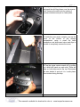
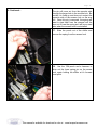
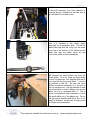
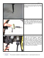
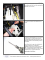
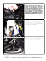
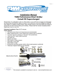
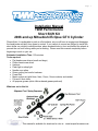
Page 1
Installation Manual
TWM Performance
Short Shift Kit
2006 and up Mitsubishi Eclipse GT 6 Cylinder
Please Note: It is preferable to park on a flat surface, as you will have to engage and disengage
the hand brake and shift from gears to neutral. If you cannot do so and are obliged to install the
short shifter on a slightly inclined surface, place wooden blocks in front and behind the wheels to
prevent the car from moving while you’re working. Please read this manual completely before
beginning to work on your car.
Estimated Installation Time: 120 minutes
Tools required:
• Flat head screw drivers (small and large)
• Philips head screw driver
• Hammer
• Flash light or shop light
• Needle nose pliers
• Rotary cutting tool and/or hacksaw
• Power Drill
• Metric socket set (with 8mm, 9mm, 12mm, 14mm sockets) and ratchet
• File and X-Acto knife
• All purpose grease (white Lithium based grease preferred)
What you get in this kit:
This manual is available for download in color at : www.twmperformance.com
Page 2
1. Unclip the snap at the top of the shift boot
and push the shift boot down over the reverse
lock. Unscrew the shift knob by rotating it
counter-clockwise and put in a safe place.
2. Inside the rear center console, pop up the
cover at the bottom of the storage
compartment using a small flat head
screwdriver and disconnect wires and clips to
be able to completely remove the cover.
3. Pop the upper center console off by pulling
on it with both hands on each side. There are
clips on both sides and at the top. Disconnect
the wire behind it and put it in a safe place.
Use caution during this step.
This manual is available for download in color at : www.twmperformance.com
Page 3
4. By placing your hands beneath both sides
of the top of this part, pull on it and disconnect
the wires behind it. Put this portion in a safe
place as well.
5. Starting from the armrest, unclip the center
console covering the handbrake and shifter
mechanism, making your way toward the front
until it is completely free.
6. Turn this portion of the console on it’s side
to gain access to the wires beneath it.
Disconnect the 12V plug wire and the heated
seats switches.
This manual is available for download in color at : www.twmperformance.com
Page 4
7. You will now have access to 8 screws.
Remove them using a Philips screwdriver.
There are 3 screws under the armrest, 4
screws in front of the shifter and 1 screw
beneath the upper center console you
removed in step 3.
This manual is available for download in color at : www.twmperformance.com
Page 5
8. The front of the main console is held in
place by plastic clips (one on each side). To
remove them, pop the center cap out with a
small flat head screwdriver and pull on it. Lift
the rear end of the main console to be able to
disconnect the heated seats controls and 12V
plug if not already disconnected. Lift the front
end of the main console and pull it out of the
car and put it in a safe place. Use caution not
to scratch the interior of the car as you do this.
This step is simplified with the handbrake
down and the front seats tilted backward.
9. Remove the clip holding the carpet to the
frame on the passenger side with a flat head
screwdriver. This will create more space to
work and will allow removal of the black plastic
cover in the next step.
10. You must now remove the black plastic
cover that goes over the entire shifter
assembly. Using a Philips head screwdriver,
remove all 4 screws, 2 on each side and set
the plastic part aside. It is not necessary to
remove the clips from the cover, it can simply
be set aside, out of the way on the drivers side
of the console. This will allow enough room to
work to install the shifter.
This manual is available for download in color at : www.twmperformance.com
Page 6
11. Pictured Left : The black plastic cover is
placed out of the way on the drivers side of the
center console.
12. Working at the bottom of the shifter itself,
spread the steel wire clip apart with your
fingers or needle nose pliers and push the
cable down. This will separate the shifter from
the shifter cable. Be sure not to lose the steel
wire clip as it needs to be used for reinstallation.
Once the shifter and plastic cup are slid out of
the shifter cable housing, the steel wire clip
can be left in place on the shifter cable to be
certain not to misplace it.
13. Place the special alignment tool provided
with the kit on to the reverse lock with the slot
facing up, and the smaller hole facing the rear
of the car. The larger hole in the alignment
tool should be facing forward, line it up with
the existing hole in the reverse lock. Be sure it
is lined up with the existing hole by looking
through the larger hole in the front of the
alignment tool, you should see a spring pin
through the existing hole in the reverse lock.
This manual is available for download in color at : www.twmperformance.com
Page 7
14. Insert the spring pin punch through the
larger hole in the alignment tool and through
the existing large hole in the reverse lock. The
spring pin punch tool needs to be lined up so
that the spring pin on the shifter shaft slides in
to it. In order to do so, apply light pressure on
the spring pin punch while moving the reverse
lock up and down a little. You will feel the
spring pin punch slide over the spring pin. It is
very important that the spring pin punch goes
through the alignment tool, through the
existing hole in the reverse lock, and over the
existing spring pin on the shifter which holds
the spring for the reverse lock. This will
ensure that everything is lined up for the
reverse lock removal.
15. This step is more easily accomplished with
the help of an assistant. One person should
operate the power drill while the other holds
the shifter shaft, alignment tool, and spring pin
punch in place. With the alignment tool and
spring pin tool in place, use a power drill and
the 1/8 inch drill bit provided with the short
shifter to drill an access hole in the reverse
lock through the smaller hole in the alignment
tool. This hole will line up with the spring pin
in the shifter and allow for removal of the
spring pin. Do not apply a great deal of force
while drilling, just enough to drill through the
plastic reverse lock.
16.
READ THIS STEP COMPLTELY
BEFORE PROCEEDING. Remove the spring
pin which holds the spring in the reverse lock
from the shifter. In order to do so, insert the
7/64 inch punch provided with the short shifter
through the hole in the reverse lock you just
drilled in the previous step. Line up the punch
with the hole in the spring pin and tilt the
shifter all the way forward until it stops. Be
certain that the shifter cable is NOT connected
to the base of the shifter during this step, it
should have been disconnected in step 12.
With an assistant holding the shifter at it’s
forward most point, use a hammer and tap the
spring pin out of the shifter a little at a time.
This manual is available for download in color at : www.twmperformance.com
Page 8
16. Continued…
The pin will come out from the opposite side
through the larger hole in the reverse lock. Be
certain it is lined up and does not contact the
opposite side of the reverse lock on the way
out. Once this pin is removed, the spring will
want to eject itself from the reverse lock, be
sure not to lose the spring as it will be re-used
later when the reverse lock is re-installed.
17. Slide the punch out of the shifter and
remove the spring from the reverse lock.
18. Use the 7/64 punch and a hammer to
drive out the lower spring pin on the revere
lock, again holding the shifter at it’s forward
most point.
This manual is available for download in color at : www.twmperformance.com
Page 9
19. With both spring pins removed, the
reverse lock can be slid off of the stock shifter,
note it’s orientation for re-installation later and
put it in a safe place.
20. In order to remove the shifter, the 2 push
clips on the passenger side of the shifter
assembly holding the two pins must be
removed or cut with a rotary tool or Dremel. If
you do not have access to rotary tool, use a
sharp flat head screwdriver and a hammer and
work your way around the push nut to remove
it. New push nuts are provided in the kit if they
are broken or cut during removal.
The easiest way to remove the clips is to slice
them with a rotary cutting tool, then to slide
them off with a flat head screwdriver.
Both methods are pictured to the left. The first
image shows removal with a hammer and
sharp flat head screwdriver, while the next two
images show removal with a Dremel tool by
slicing the clips and sliding them off with a
screwdriver. Be sure to wrap shop towels or
rags around the shift assembly to protect the
interior from any debris while cutting.
Continued on next page…
This manual is available for download in color at : www.twmperformance.com
Page 10
20 Continued.
21.
Disconnect the shifter cable which
controls side to side motion from the triangular
plastic side arm. This can be achieved simply
by prying with a flat head screwdriver to slide it
off the steel pin on the triangular arm.
22. With the 2 clips removed and side shifter
cable disconnected, push the two pins out of
the assembly using a hammer and a small
punch. Do not use the 7/64” punch provided
with the kit as it is too small in diameter. Use
a sturdy larger punch or screwdriver instead.
This manual is available for download in color at : www.twmperformance.com
Page 11
23. The shifter can now be pulled up and out
of the shift assembly. Pay close attention to
how the spring is installed on the side arm as
you will have to re-install it later.
24. Inspect the stock shifter and take note
how it is installed in the plastic upper
assembly for re-installation later. Pull off the
white base cap with the o-ring (not the small
pivot cup at the bottom of the shifter but the
white part that the shifter pivots in) and
remove the shifter from the assembly.
25. Remove the small plastic cup from the
stock shifter. To do so, hang the stock shifter
on the Cup Remover Tool supplied with the kit
on a vice with the jaws open about 1 ½ inches
as pictured to the left. Be sure the stock
shifter is inserted completely in to the slot in
the cup remover tool. Ask an assistant to hold
the stock shifter to avoid it falling to the ground
when the cup is separated from it. Use a
punch or screwdriver and a hammer to punch
the stock shifter out of the plastic cup. Do not
use the punch supplied with the kit as it is too
small in diameter, instead use a large punch
or Philips head screwdriver.
This manual is available for download in color at : www.twmperformance.com
Page 12
26. Grease the small ball on the TWM short
shifter as shown at left and press the cup you
removed in the previous step on to the TWM
short shifter.
27. Grease the main pivot ball on the TWM
short shifter. Re-assemble the upper portion
of the assembly with the TWM short shifter in
place. Set aside and move on to the shift
assembly modification.
28. Now the shift assembly must be removed
from the car to be modified.
Begin by
detaching the shift cables from the shift
assembly by pulling up on them. Unclip all
wires from the plastic shift assembly in order
to remove it. For most of the wires clipped to
the assembly, you can simply cut the electrical
tape that secures them to the clips on the
assembly. The rest of the clips can be pulled
up to disconnect from the assembly.
This manual is available for download in color at : www.twmperformance.com
Page 13
29. Using a ratchet with an extension and a 12
mm socket, unbolt the four bolts securing the
assembly to the floor pan.
30. Remove the plastic shift assembly from
the car.
31. Place the shift assembly in a vise to hold it
securely upright. In order to make room for
the longer portion below the pivot point on the
TWM short shifter the shift assembly needs to
be modified.
Use a Dremel tool or any rotary cutting tool to
remove the portions of the assembly
highlighted in the picture to the left on the next
page. We recommend using a Dremel tool
with a cutting bit as pictured to the left, it works
extremely well for cutting through plastic.
Contunued on Next Page…
This manual is available for download in color at : www.twmperformance.com
Page 14
31. Continued. The picture to the left shows
the modified assembly with the plastic portions
removed. Use a file or X-Acto knife to smooth
out the edges once the plastic assembly is cut.
32. PLEASE NOTE: The following steps are
only required if you have purchased the
optional shift assembly bushings with your
TWM short shifter. If you do not have the
base bushings, proceed to step 35.
Remove the four steel inserts at each corner
from the bottom of the shift assembly with a
flat head screwdriver.
This manual is available for download in color at : www.twmperformance.com
Page 15
33. Remove the rubber bushings from the
base of the assembly by pushing them
through the assembly with a flat head
screwdriver or with your fingers.
34. Re-install the modified shift assembly in
the car with the TWM base bushings. While
placing the assembly into the car, be sure to
place the shifter cables where they will go, do
not re-connect them to the assembly yet.
Install the base bushings beneath the shift
assembly with the smaller diameter step
facing up. This step fits in to the holes in the
plastic assembly to replace the rubber
bushings you removed in the previous step.
Install a bushing at each corner of the shift
assembly.
35. Secure the shift assembly back in place
with the stock bolts and a 12mm socket. Be
sure the step on the bushings at each corner
of the assembly are in the holes in the
assembly properly before tightening it down.
Clip the shifter cables back to the assembly
and re-connect the wires to the shift assembly
with electrical tape if you cut the tape initially.
If you did not cut the tape and removed the
clips securing the wires, replace the clips now.
This manual is available for download in color at : www.twmperformance.com
Page 16
36. With the modified shift assembly bolted in
to the car, Install the upper portion of the
assembly with the TWM short shifter in place.
37. Re-install the triangular shaped plastic
arm and spring which controls side to side
resistance. Re-insert both pins that go
through the assembly and the upper portion of
the assembly taking care to properly re-install
the triangular shaped plastic side arm and
spring on to the TWM short shifter. Reconnect the shift cable to the triangular
shaped arm now.
38. Secure the pins in the assembly once
they are all the way through with the supplied
push clips. Use a 9mm socket to install the
6mm push clip on the smaller pin by driving it
on with a ratchet extension. Use a 14mm
socket to install the 10mm push clip on the
larger front pin by driving it on with a ratchet
extension. You should be able to install these
clips by hand, make sure they are pushed all
the way on to prevent the pins from sliding out
over time. It may be necessary to hold the
pins from the driver’s side to keep them from
moving while pushing the clips on from the
passenger side.
This manual is available for download in color at : www.twmperformance.com
Page 17
39. Lightly grease the TWM shifter shaft and
slide the reverse lock on to the short shifter.
Be sure it’s orientation is correct, the small
hole you drilled should face the back of the car
and the larger pre-existing hole should face
the front of the car.
40. Be sure the bottom shifter cable is not
connected to the shifter at this point. Use
the spring pin punch tool supplied with the
short shifter to begin installation of the
supplied 3mm x 24mm lower spring pin
through the reverse lock and the shifter shaft.
There are 2 spring pins supplied with the kit,
you will be installing the longer of the two in
this step. In order to do so, insert the spring
pin in to the end of the spring pin punch to
hold it. This punch is used only to start the
spring pin in the hole in the shifter shaft. Line
up the lower slot in the reverse lock with the
lower hole in the shifter shaft. Ask an
assistant tohold the reverse lock in place while
you work.
41. Line up the spring pin with the hole in the
shifter shaft and tap it in gently with a hammer
to get it started. Lean the shifter as far
forward as it will go in the assembly to stop it
from moving as you tap with a hammer. You
only need to get the sping pin started with this
punch. Once the spring pin is started, tap it in
about 1/8th of an inch and stop. Be sure not
to drive the pin in far enough to contact the
reverse lock with the spring pin punch tool as
this may cause damage. Use the supplied
long and thin 7/64 inch punch to complete
driving in this pin. Drive it in far enough so
that it is flush on both the front and rear of the
reverse lock.
This manual is available for download in color at : www.twmperformance.com
Page 18
42. Re-install the spring in to the reverse lock.
43. Lean the shifter all the way back now, as
though it were in 4th gear. Be sure the lower
shifter cable is not connected. Use the
slotted end of the spring compressor tool to
compress the spring ensuring that the slot in
the tool faces front to back. Using this tool to
depress the spring you will be able to see the
upper hole in the shifter shaft looking through
the larger existing hole on the front of the
reverse lock.
44. With the spring depressed, insert the
spring pin punch tool through the larger preexisting hole in the reverse lock to start the
shorter spring pin supplied with the kit in the
upper hole in the shifter shaft. This spring pin
serves to hold the spring depressed so it is
important to install the spring pin with the
spring depressed lower than the hole in the
shifter with the slotted spring compression
tool. The spring compression tool is designed
with a slot wide enough to allow the spring pin
punch tool to pass through it. Use the tool to
start the spring pin and drive it in with a
hammer until the spring pin punch tool nearly
touches the shifter shaft and stop.
This manual is available for download in color at : www.twmperformance.com
Page 19
45. Still holding the spring depressed, finish
installing the upper short spring pin with the
supplied long and thin 7/64 inch punch and a
hammer. It is very important to drive it in so
that there is enough clearance on either end of
the spring pin to allow the reverse lock to
move up and down freely, while still holding
the spring in place. The postion of the pin can
be adjusted with the long and thin punch to
ensure smooth operation of the reverse lock.
46. With the reverse lock completely reinstalled, you can now re-connect the lower
shifter cable. Ensure all gears work properly
and reverse can be engaged.
47. Re-install the center console, re-connect
all wires and connectors, and install the shift
knob. You are done, enjoy the drive !
This manual is available for download in color at : www.twmperformance.com
Page 20
Legal Disclaimer
TWM Performance is not responsible for the misuse, incorrect installation, or failure of any product we sell.
Under no circumstances, including but not limited to negligence, will TWM Performance be liable for special or consequential damages that result
from the use or inability to use our products. TWM Performance does not assume responsibility for any damage to the user, passenger or vehicle
resulting from the operation of a TWM Performance product.
TO PROTECT USERS FROM INJURY OR DEATH. THE USER ASSUMES ALL RISKS. Autocrossing, track events, and high speed driving are all
dangerous activities - always drive responsibly and safely.
Warranty
Installation of some TWM Performance products may or may not void factory warranties. Always keep OEM equipment that has been replaced in
case work is required at the dealer or the vehicle is sold.
This warranty covers the original purchasing consumer. This warranty is limited to repair or replacement by TWM Performance of any TWM
Performance product that fails because of a defect in materials or workmanship.
Warranty does not cover the following:
-Damage incurred to related vehicle components
-Regular day to day wear on vehicle
-Shipping costs for replacements
-Installation costs and vehicle down time
-Products that have been modified, incorrectly installed or misused.
-Mounting hardware and bearings
This manual is available for download in color at : www.twmperformance.com