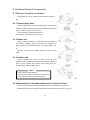
1
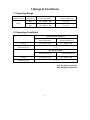
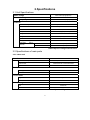
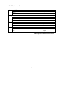
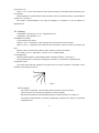
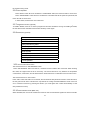
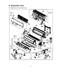
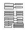
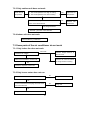
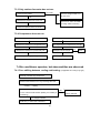
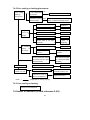
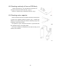
SPLIT TYPE
AIR CONDITIONER
Service Manual
AA-2710
0
CONTENTS
1.Range & Conditions ........................................................................................................ 2
1.1 Operating Range..................................................................................................... 2
1.2 Operating Conditions .............................................................................................. 2
2.Specifications .................................................................................................................. 3
2.1 Unit Specifications................................................................................................... 3
2.2 Specifications of main parts..................................................................................... 3
2.3 Specifications of other parts .................................................................................... 5
3. Control Specifications ................................................................................................... 6
3.1.System source ........................................................................................................ 6
3.2 Control functions ..................................................................................................... 6
3.3 Operating mode ...................................................................................................... 7
3.4 Protection function ................................................................................................ 10
3.5 Other functions...................................................................................................... 12
4. Exploded view .............................................................................................................. 16
4.1 Exploded view for indoor unit ................................................................................ 16
4.2 Exploded view for outdoor unit .............................................................................. 18
5. Refrigerant Flow Diagram............................................................................................ 20
6. Circuit Diagram............................................................................................................. 21
6.1 Electrical wiring diagram for indoor unit ................................................................ 21
6.2 Electrical wiring diagram for outdoor unit .............................................................. 21
7 Troubleshooting............................................................................................................... 22
7.1 Check before troubleshooting ............................................................................... 22
7.2 The air conditioner does not work ......................................................................... 22
7.3 Some parts of the air conditioner do not work ....................................................... 24
7.4 Air conditioner operates, but abnormalities are observed ..................................... 25
7.5 Sensor is defective (Check reference 3.4.8) ......................................................... 26
8. Checking Electrical Components.................................................................................... 27
8.1 Measure insulation resistance............................................................................... 27
8.2 Checking continuity of fuse on PCB Ass'y............................................................. 28
8.3 Checking motor capacitor...................................................................................... 28
1
1.Range & Conditions
1.1 Operating Range
Operating Modes
Temperature
Indoor Temperature
Outdoor Temperature
Max.
32℃ DB/23℃ WB
43℃ DB
Min.
21℃ DB/15℃ WB
21℃ DB
Cooling
1.2 Operating Conditions
Rated Operating Conditions
Cooling
Indoor Temperature
Outdoor Temperature
27℃ DB/19℃ WB
35℃ DB/24℃ WB
Tubing Length (m)
3.0
Max. Operating Value
Indoor Temperature
Cooling
Outdoor Temperature
32℃ DB/23℃ WB
Tubing Length (m)
43℃ DB/26℃ WB
3.0
DB: Dry-bulb temperature
WB: Wet-bulb temperature
2
2.Specifications
2.1 Unit Specifications
220V/ 60Hz (single phase)
Rated voltage
AA-2710
Electrical rating
198~242V~/60Hz (single phase)
Voltage range
Features
Controls / Temperature control
Microprocessor / I.C thermostat
Control unit
Control panel of indoor unit
Air filter
Anti-mold, washable
Compressor
Rotary-type (Hermetic)
Refrigerant
R22
Refrigerant control
Capillary tube
Pipeline connection manner
Flare
Max. pipeline length
Refrigerant
diameter
tubing
m
9
Narrow tube
mm
6.35 (1/4”)
Wide tube
mm
12.7 (1/2”)
Data subject to change without notice
2.2 Specifications of main parts
2.2.1 Indoor unit
Controller
AA-2710
Controls / Temperature control
Microprocessor / I.C thermostat
Control unit
Infrared remote control transmitter
Fuse
Fan &
250V T3.15A
Fan motor
Fan type
Cross-flow fan
Fan motor model
RPS19E-6
Louver motor
Type
Step motor
Model
24BYJ48-Q1
Heat exchanger
Fin
Aluminum
tube
Copper
Data subject to change without notice
3
2.2.2 Outdoor unit
Controller PCB
Part No.
-
Fuse
-
Compressor
model
QXT-18B(F)
Safety devices Type
B250-150-241E
Operating capacitor
20
μF/ VAC
Fan & Fan motor
Fan type
Propeller fan
Fan motor model
YDK36-6D-5
Heat exchanger
Fin
Aluminum fin
tube
Copper
Data subject to change without notice
4
2.3 Specifications of other parts
Indoor unit
Transformer
Indoor temperature
Thermal resistor
Resistance temperature 25℃
KTEC-41-C12
Coiled pipe
KTM-41-C9
10
KΩ
Power supply length (m)
/ cross section (mm2)
1.5/1.0
Rated value
10A,250VAC
Power relay
G4A-1A-E 12VDC Or
JQX-102F-012
JZC-32F-012-1H1
Coil rated voltage,
12V d.c
12V d.c
Current coil resistance(20℃)
200Ω
300Ω
Data subject to change without notice
5
3. Control Specifications
3.1. System source
1.1 Signal input
Temperature sensor signal (indoor temperature , indoor coiled temperature, outdoor coiled
temperature); remote control signal; key input.
1.2 Signal output
LED×4 (SI, SCK, RCK or air refresh, operation, pause, timer); louver motor (a, b, c, d); buzzer,
compressor, 4-way reversing valve, indoor fan motor (H,L), outdoor fan motor, AUH, air refresh, and other
assistant functions.
3.2 Control functions
2.1 Switches input:
Press the Emergency button on the panel when the air conditioner is in the off mode, then the unit will
be turned on and work in the “SMART” mode. Press this button again when the unit is running (including
test run or in “SMART” mode), the air conditioner will be turned off.
Note:
All the displaying will disappear when turn off the air conditioner by pressing the Emergency button.
2.2 Timing off
“Timing off ” function is only effective when the air conditioner is running. The indoor unit will display “
TIMING” when this function is effective. The unit will be turned off at the set time and “ TIMING” signal will
disappear. When the user turn off the unit ahead of the set time by remote controller or Emergency button,
the “Timing off” function will be canceled.
Note: The set time for Timing off is 1-8 hours.
2.3 Sleep mode:
When the sleep mode is set by remote, the set temperature will increase 1℃ after running 1 hour in
Cooling or Dehumidifying mode. Temperature will decrease 1℃ after running 1 hour in heating mode. Note
:Display set temperature is unaltered
When the air conditioner runs in sleep mode, the Max. indoor fan speed is set at medium level.
Note:
The fan speed is set to be at low level, but the fan speed will turn into medium level when in
freeze-prevention mode.
2.4 Unit type and Power
Please refer to PIN function
Note: After changing the unit type, the new unit type should be tested for the relevant function and
protection differently according to different unit types.
6
2.5 Blowing surplus energy function:
The first situation: When the unit is turned off in heating operation, the time for blowing surplus energy is
80 seconds. When Trc<32℃, the louver is in position 5 ( Fan speed is at low level).
The second situation: When the unit enters defrosting when in heating operation, the time for blowing
surplus energy is 30 seconds. When Trc<32℃, the louver is in position 5 ( Fan speed is at low level).
The third situation: In heating operation, when the unit comes to the set temperature, the compressor
will stop. When Trc<32℃, the louver is in position 5 ( Fan speed is at low level).
The fourth situation: In heating operation, when the unit enters heating overload operation, the
compressor will stop, (Trc≥c℃ and the compressor continues working for more than 5 minutes, the
compressor stops) and blow surplus energy; When the temperature of indoor pipe drops to E℃, the unit will
exist from overload protection and Indoor fan motor will operate at low level for 80 seconds. When Trc<32
℃, the louver is in position 5.
The fifth situation: If the unit has the function of starting up automatically when the electricity comes again,
the unit will judge before the starting of compressor: When Trc≥F℃, the indoor fan motor will run at low level
and the louver is in position 5. When Trc≤25℃, the indoor fan motor will stop. The unit will enter
freeze-prevention operation after the compressor starts.
2.6 Operation for dryness enzyme-prevention
When the unit is turned off in cooling mode, the indoor unit will continue run in low fan speed for about 3
minutes to remove the partial moisture in the room.
2.7 Compensation for temperature
When enters heating operation, the indoor temperature will decrease 3℃ automatically.
3.3 Operating mode
3.1 SMART operation
The unit will judge the operation mode automatically after receiving the SMART signal.
3.1.1 When Tr≥24℃, turns on the unit in the original condition, the unit will turn into cooling mode.
When 20℃<Tr<24℃, the unit will turns into airflow mode.
When Tr≤20℃, the unit will turns into heating mode.
In airflow mode, when in the condition that it is necessary for cooling or heating more than 1 minute, the
unit will turn into cooling or heating mode.
3.1.2 The fan speed is at auto mode and adjustable, the display will change accordingly.
Note: If choosing the airflow mode, the auto airflow is set to be at low level automatically.
7
3.3.3 The airflow direction is swing and adjustable, and the display will change accordingly.
3.3.4 All output (air refresh, AUH, air ventilate, etc.) is effective.
3.3.5 In cooling mode, the original set temperature is Ts=Tr-5℃ and 22℃≤Ts≤27℃, then the master unit will
not change operation mode when the unit enters cooling mode.
If users want to change working condition by remote controller, in case the condition will not conflict with the
master unit mode, ( such as cooling mode conflicts with AUH mode), the master unit will operate and
display in new condition set by remote controller.
3.3.6 In heating operation, when the temperature Ts=Tr+8℃ and 16℃≤Ts≤22℃, then the master unit will
not change operation mode when the unit enters heating mode.
If users want to change working condition by remote controller, in case the condition will not conflict with the
master unit mode, the master unit will operate and display in new condition set by remote controller.
3.2 Cooling:
Temperature control range: 16℃-32℃; Original value: 24℃;
Temperature control precision: ±1℃;
Characters on control:
4-way reversing valve closes:
When Tr≥Ts+1℃, compressor runs; When Tr≤Ts-1℃, compressor stops; The control circuit will stop
compressor only after it has run at least 5 minutes. The compressor can be restarted 3 minutes later the
turn-off.
Fan speed control:
Auto: When Tr>Ts+2℃, high speed;
When Ts< Tr≤Ts+2℃, medium speed;
When Tr≤T, low speed.
Manual: Users can select the fan speed of high, medium or low level as needed when the air
conditioner is in the turn-on status.
Louver adjustment:
Manual (vertical direction): Set the blades position as needed. (Position 1-5 in figure 1.)
Auto (vertical direction): The range of sweeping is in position 2-5, swinging speed is 5 degree/second.
3.3. Dehumidification:
Temperature control range: 16℃-32℃; Temperature control precision: ±1℃;
Characters on control:
4-way reversing valve closes.
When Tr≥Ts+2℃,the running mode is the same to the cooling operation;
When Ts-1℃< Tr < Ts+2℃, compressor and outdoor fan motor run continuously. And indoor fan motor
runs at low fan speed
When 15℃< Tr < Ts-1℃, compressor and outdoor fan motor are working according to 3 minutes
working alternating with 9 minutes stopping. Indoor fan motor runs at low fan speed when compressor is
running, and it runs at breeze level for 30 seconds later the turn-off of compressor. 30 seconds later, fan
8
motor will turn off.
When Tr≤15℃, indoor and outdoor fan motor will stop running, louver blades (vertical direction) can’t
be controlled.
Manual operation in vertical direction: When necessary, users can select the position of louver blade in
position of 1~5 in Figure 1.
Fan sweep in vertical direction: The range of sweeping is in position 2-5, the fan speed is 5
degree/second.
3.4. Heating
Temperature control range: 16℃-32℃; Original value: 24℃;
Temperature control precision: ±1℃;
Characters on control:
4-way reversing valve opens.
When Tr≤Ts-1℃, compressor, 4-way reversing valve and outdoor fan motor all open.
When Tr≥Ts+1℃, compressor and outdoor fan motor both close; Indoor fan motor is running at low
level.
Manual: Users can select the fan speed of high, medium or low level as needed.
Auto: When Tr< Ts-2℃, high speed; When Tr≥Ts-2℃,medium speed;
Louver adjustment:
Manual (vertical direction): Set the blades position as needed. (Position 1-5 in figure 1.)
Auto (vertical direction): The range of sweeping is in position 1-4, fan speed is 5 degree/second.
Compressor control:
The control circuit will stop compressor only after it has run at least 5 minutes. Compressor can be
restarted 5 minutes later the turn-off.
5
4
3
2
1
Fig.1
3.5 Fan sweep
In this mode, compressor, 4-way reversing valve and outdoor fan motor all open.
Indoor fan motor can be set at high, medium, low level as needed.
Manual (vertical direction): Set the blades position as needed. (Position 1-5 in Figure 1.)
Fan sweep in vertical direction: The range of sweeping is in position 2-5 in Figure 1, fan speed is
5 degree/second
9
3.4 Protection function
3.4.1 Delay-starting protection for the compressor
Compress will restart working 3 minutes (5 minutes in HEAT mode) later the turn-off of compressor or
power-off to keep the pressure balance of the cooling system.
3.4.2
Cool-airflow-prevention:
In heating operation, the time for compressor running or stopping can not be longer than 5 minutes.
When the unit is in operation and the compressor has not been started yet, Trc≥F℃, then indoor fan motor
runs at low level. ( blades is at position 5 and can not be controlled). When Trc≤25℃, the indoor fan
motor stops.
In operation, if compressor has been turned on and running time is no longer than 5 minutes,
A.
If Trc<F℃, indoor fan motor stops.
B.
F℃≤Trc≤36℃, indoor fan motor runs at low level.
C.
Trc>36℃, indoor fan motor runs at the set level.
Note: As long as comes into A condition, the unit will not enter A condition even if temp. drops. As long
as comes into C condition, the unit will not enter B condition even if temp. drops. Louver blades will come to
5 position automatically and not controllable. During cool-airflow-prevention period, PAUSE (red) indicator
will light.
3.4.3 Dew- prevention (cooling&dehumidification mode)
When the louver blades are at the position 1,2,5 as shown in Fig.1 for at least 15 minutes, the blades will
come back to 3 position automatically and now the position for louver blades can be adjusted.
Note: There would be no dew-prevention when at high airflow level.
3.4.4 Freeze-prevention: To prevent indoor heat exchanger freezing in COOL and DRY
operation.
When Trc≤3℃, the unit will enter freeze-prevention operation. If indoor fan speed is at low or breeze
level, it will turn to medium speed automatically; if indoor fan speed is at medium speed, it will turn to high
speed;, The air conditioner will exit Freeze-prevention operation when Trc>10℃, indoor fan motor runs at
the set fan speed. Compressor will stop running when it runs at least 10 minutes and Trc≤0℃. If the
off-time of compressor is for more than 6 minutes or Trc≥10℃, and the compressor stops running for more
than 3 minutes. Compressor and outdoor fan motor will restart working. The air conditioner will exit
Freeze-prevention operation, and indoor fan motor is running at the set speed.
3.4.5 Heating overload working:
When T≥G℃, indoor fan speed will turn to low level.
If T begins to descend, when T<H℃ and the time for fan speed transition is longer than 5 minutes, then
indoor fan motor returns to normal fan speed.
If T go on ascending, when T≥I℃, then compressor stops and outdoor fan motor go on running. Indoor fan
10
motor turns to low speed; When T<H℃, compressor, indoor and outdoor fan motor return to normal running
( there is 3 minutes protection for compressor).
3.4.6 Heating overload working: (not available for cooling-only type air conditioner)
When Trc≥A℃, the unit enters heating overload protection. If indoor fan speed is set at low or breeze
level, it will turn to medium speed automatically; if indoor fan speed is set at medium speed, it will turn to
high speed; When Trc≥B℃, outdoor fan motor stops. When indoor pipe temp. drops to D℃, outdoor fan
motor will restart working. Air conditioner will exit overload protection when Trc drops to E℃, compressor
restarts working, Indoor fan motor runs at the set fan speed.
When Trc≥C℃and the build-up time of compressor running is for more than 5 minutes, compressor
will be stopped. When indoor pipe temp. drops to E℃, outdoor fan motor will returns to normal running.
Note: When entering heating overload operation, louver blades are in position 3 and return to the original
position.
3.4.7 Defrosting:
3.4.7.1 Defrost entry conditions:
Defrost condition has three branches which has something in common:
☆
A Compressor is running.
☆
B Compressor has been running for more than 10 minutes.
Difference between the three branches:
A.
The first branch:
a.
When the temperature of indoor pipe begins to descend, the sum of descending value has
reached or exceeded 3℃ and the temperature of indoor pipe will not go up in 3 minutes.
B.
b.
The build-up time of compressor running is for more than 40 minutes.
c.
TOC <-1℃
d.
TRC- TR <18℃
The second branch:
a.
The build-up time of compressor running is for more than 48 minutes.
b.
TOC <-5℃
c.
The present value is 3℃ lower than the lowest value of TOC re in 12 minutes after the unit has
started.
C.
The third branch:
a.
The build-up time of compressor running is for more than 27 minutes.
b.
TOC <-5℃ for more than 20 seconds.
Note:
When the system has entered heating overload protection and has not existed from protection, the
unit can not enters defrosting; Users can only test defrosting conditions after existing from protection for 3
minutes.
11
3.4.7.2 Defrosting:
Compressor and outdoor fan motor will stop working after the unit entering defrosting running. 5
5seconds later, 4-way reversing valve will close. Another 5 seconds, compressor starts running. When the
time of the compressor running is for more than 8 minutes or Toc≥35℃, compressor stops. 55 seconds
later, 4-way reversing valve will open. Another 5 seconds later, compressor and outdoor fan motor will
restart working and exit defrosting operation. In defrosting operation, the time of compressor running is at
least 3 minutes. Cool-airflow-prevention and blowing residue heat are both effective.
3.4.8 Testing codes:
Code 1 is to set test run (Not effective for “SMART” mode and “DEHUMIDIFICATION” mode. After entering
testing run, no matter what is the set temperature or indoor temperature, the unit will run as the set cooling
or heating mode and will also not detect stopping condition. The max. running time is 60 minutes.)
Code 2 is to set fast testing.
Code 3 is to set auto-diagnosis.
Code 4 is to cancel the above setting.
There only can be one setting each time in the tests above.
3.4.9 Failure code display and protection
A. Temperature can be checked by codes, code 11 displays room temperature, code 12 displays
indoor pipe temperature, code 13 displays outdoor pipe temperature.
B. Code 14 displays abnormal information.
E0 displays normal operation.
P2 displays heating overload.
P3 displays freeze-prevention protection.
F1: The circuit of room temperature sensor is damaged or abnormal.
F2: Indoor pipe.
C.The circuit of room temperature sensor is abnormal---Pause light flashes and the unit stops.
D. The circuit of indoor pipe temperature sensor is abnormal---Timer light flashes and the unit stops.
E. The circuit of outdoor pipe temperature sensor is abnormal---Run light flashes and the unit stops.
3.5 Other functions
3.5.1 Auto-diagnosis
The Auto-diagnosis functions are in the following steps:
Buzzer beeps 1s →no output 0.5s→running indicator lights 0.5s→pause indicator lights 0.5s→timer
indicator lights 0.5s→air refresh indicator lights 0.5s →running compressor on 0.5s→outdoor fan motor
0.5s→4-way reversing valve 0.5s→AUH 0.5s→indoor fan motor high level 0.5s→indoor fan motor medium
level 0.5s→indoor fan motor low level 0.5s→air refresh indicator lights 0.5s→FLAP-a 0.5s→FLAP-b 0.5s→
FLAP-c 0.5s→FLAP-d 0.5s→no output 0.5s→all output 1s.
3.5.2 Time reducing:
12
The CPU runs as 60 times as the former speed. (There is no timer reducing function within 1 minute)
3.5.3 AUH
A. Starting conditions for AUH
a. Having received starting AUH signals from remote controller.
b. In the heating mode.
c. The build-up time of compressor is more than 3 minutes.
d. Tr≤18℃
e. Ts-Tr≥3℃
f. Indoor fan motor is running at medium or high level.
B. The AUH function will be closed when meets any of the following conditions:
a. Tr≥18℃
b. Ts-Tr≤2℃
c .Trc≥A-2℃
d. Indoor fan motor stops running or runs at low level.
e. Entering defrost running.
f. Having received signals for closing AUH from remote controller.
Note: If AUH stops working because of condition c, users can restart AUH only on condition that indoor pipe
temp. ≤E℃ and meet all conditions in A.
C. Defrost when AUH is in operation
If AUH is in operation or less than 10 minutes after closing, indoor fan will continue running at low level for
30 seconds when entering defrosting.
D. Switch off unit when AUH is in operation.
If AUH is in operation or less than 10 minutes after closing, indoor fan will continue running for 30 seconds
when switching off. The other things are the same to the condition when switching off normally.
3.5.4 Display function:
The central display screen does not display symbols if air conditioner is in off status, but Timer indicator
lights when in Timer mode. In the checking and setting conditions, the screen will also display the
corresponding state of the unit.
Turn on the master unit, the screen will only display run indicator after 30 seconds. The screen will
display all settings if remote control signal is received again, and only display run indicator after receiving
the last signal from remote controller 30 seconds later.
Note:The content LBD displays. The screen displays actual operation mode of the unit.
3.5.5 Air refresh function:
Press air refresh button when the unit is in off status, the unit will switch on. Indoor fan motor runs at the
set fan speed, air refresh outputs. Press this button again, air refresh function is cancelled and the unit will
turn back to the original mode. Press air refresh button if the unit is running, air refresh indicator will light
and air refresh output. Press this button again, air refresh function is cancelled and the unit will turn back to
13
the original running mode.
3.5.6 Quiet Operation
Press “QUIET” button when air conditioner is “FAN SWEEP” status, the indoor fan will run at low level.
Press “AIR REFRESH” button when air conditioner is in off status and set fan speed as quite mode, the
indoor fan will run at low level.
In other status, the indoor fan runs at low level.
3.5.7 Restoration function (optional)
2
2
To install E PROM, users do not have to program first and then assemble. As long as installing E PROM,
the unit will have the restoration function after electricity comes again.
3.5.8 Restoration (optional)
Mode
Fan speed
On/Off status
Dew-prevention symbol
Fan sweep symbol
Sleep symbol
Quiet symbol
AUH symbol
Air refresh symbol
Set temperature
Louver position
3.5.9 The second function button
The second function for “AIR REFRESH” button:
Press “AIR REFRESH” button and hold on, and finish the test condition after 5 seconds. When entering
this mode, the original value is 00 for each entry. The second function is only effective for temperature
control button, on/off button, and air refresh button. Other buttons are not effective for the second function.
The second function for “AUH” button:
Press “AUH” button and hold on for 5 seconds, the unit will enter dew-prevention function. At the same time,
the unit gives a buzz sound. This button is only effective in Cooling and Dehumidification mode. Users can
set or cancel this function by pressing this button. (Y2 model gives tacit consent automatically to start
dew-prevention function.)
3.5.10 Demonstration Mode: (Blank unit)
When electrified, the unit runs at medium level if the unit has not received the signal from remote controller.
14
Pause indicator lights 1s→running indicator lights 1s→timer indicator lights 1s→air refresh indicator lights
1s →Pause indicator lights 1s→……; The display screen displays every 11,22,33,44,55,66,77,88,99,00
1s circularly.
After receiving the signal from the remote controller, the unit will operate by the signal.
During the courts of demonstration, all signals of outdoor unit are ineffective.
3.6. Temperature table of protecting point
MODEL
A
B
C
D
E
F
G
H
I
J
K
L
M
N
AA-2710
54
57
70
48
46
34
42
28
53
41
23
53
43
53
15
4. Exploded view
4.1 Exploded view for indoor unit
TYPE A
TYPE B
16
No.
NAME OF PART
No.
NAME OF PART
01
AIR FILTER
25
DISPLAY BOX
02
COVER OF ELECTRIC CONTROL BOX
31
VAPORATOR
03
WALL MOUNTING
32
ADIABATIC BUSHING
04
TUBE
PLATE
41
AIR-GUDING BRACKET
05
TUBE PLATE
42
CONNECTING BAR
06
BOTTOM FRAME
43
AIR-GUDING BLADE
07
LEFT BRACKET
44
FLAP
08
BEARING SUBASSEMBLY
45
STEP MOTOR
09
CROSS FAN
46
DRAINAGE PIPE
010
FAN MOTOR
51
ELECTRIC CONTROL BOX
011
RIGHT BRACKET
52_1
P.C.B
11
FRONT PANEL
52_2
P.C.B
12
DISPLAY WINDOW
53
CONNECTION TERMINAL BOARD
21
MEDIAL FRAME
54
POWER CORD
22
DISPLAY BOARD
56
TRANSFORMER
23
BOLT COVER
57
REMOTE CONTROL
24
DI SPLAY BOX COVER
PLATE
SUBASSEMBLY
17
4.2 Exploded view for outdoor unit
18
No.
NAME OF PART
No.
NAME OF PART
01
COVER PLATE
13
RIGHT HANDLE
02
CONDENSER ASSEMBLY
21
MOTOR BRACKET
03
CAPILLARY ASSEMBLY
22
FAN MOTOR
04
RIGHT SIDE PANEL
23
FAN
05
HANDLE COVER
24
NUT
06
COMPRESSOR
31
ELECTRIC CONTROL BOARD
07
VALVE MOUNTING BOARD
32
FAN MOTOR CAPACITANCE
08
CUT-OFF VALVE (SMALL)
33
CLIP
09
CUT-OFF VALVE( BIG)
34
COMPRESSOR CAPACITANCE
010
CHASSIS ASSEMBLY
35
CONNECTION TERMINAL BOARD
011
PARTITION BOARD
36
LEAD LOWER PRESSURE PLATE
012
SOUND INSULATION ASSEMBLY
37
LEAD UPPER PRESSURE PLATE
11
FRONT PANEL
41
INHALE PIPE
12
FAN COVER
42
EXHAUST PIPE
19
5. Refrigerant Flow Diagram
Tube
Narrow tube
Wide tube
Diameter
Φ6.35mm
Φ12.7mm
Thermal insulating of refrigerant pipeline
To prevent heat loss and condensed water from dropping on the floor, the wide and narrow tube of
air conditioner should be wrapped with thermal insulating materials. For using capillary tube, and the
tubes are in low temperature, the thickness of thermal insulating materials shall be more than 8mm.
20
6. Circuit Diagram
6.1 Electrical wiring diagram for indoor unit
Warning
To avoid electrical shock hazard, be sure to disconnect power before
checking, servicing and/or cleaning any electrical parts.
6.2 Electrical wiring diagram for outdoor unit
Warning
To avoid electrical shock hazard, be sure to disconnect power
before checking, servicing and/or cleaning any electrical parts.
21
7 Troubleshooting
7.1 Check before troubleshooting
Warning:
High-voltage will result in electric shock or death.
Always cut off the power before checking and maintaining.
7.1.1 Check power line
To check whether the power line is connected correctly to the terminal No 1 which is on the
terminal block of the indoor unit
Brown
1
2
3
Blue
N
1
N 2
Yellow/Green
4
5
7.1.2 Check unit wiring
To check whether the inter-unit wires are connected correctly.
7.1.3 Check power supply
To check whether the power supply is in the specified range.
7.1.4 Check connector and lead wire of indoor and outdoor units.
To check whether the insulating cover of the lead wire is damaged.
To check whether the lead wire and the connector are connected well
To check wires.
7.2 The air conditioner does not work
7.2.1 Leakage protector is open or fuse is burnt.
A. Setting leakage protector to “ON”, it opens immediately (can not reset).
There is possibility of ground fault.
Check insulation resistance (The insulation resistance shall be more than 2MΩ).
22
B. Leakage protector is OFF.
Disconnect unit wires from terminal block of
outdoor
unit.
And
measure
No
insulation
Poor insulation performance
Measure the insulation resistance of
resistance of outdoor unit.
the electric parts of outdoor unit.
Disconnect unit wires from terminal block of
No
indoor unit. Unplug the unit and measure
Poor insulation performance
Measure the insulation resistance of
the insulation resistance of indoor unit.
the electric parts of outdoor unit.
C. The fuse is open in several minutes after turning air conditioner on.
No
Check the rated power of fuse.
Replace it with a proper one
Yes
No
Check the resistance of indoor fan motor coil.
Replace indoor fan motor.
Yes
No
Check the resistance of transformer coil.
Replace transformer.
7.2.2 The indoor and outdoor units do not work.
No
Check power supply.
2. Check the breaker.
Yes
Check
if
something
residue
1. Power failure
cover
on
Yes
transmitting part of the remote controller.
Clean it.
No
Yes
Check if infrared receiver on indoor unit is dirt.
Clean it.
No
Check fuse on indoor PCB Ass’ y.
Yes
Check the resistance of indoor fan motor coil.
No
Measure the resistance of compressor coil.
Parts of indoor PCB Ass’ y or
switches are defective.
Measure the resistance of power transformer.
23
7.2.3 Only outdoor unit does not work.
Check the set
1. The set temperature is too high in cooling.
temperature
2. The set temperature is too low in heating.
Yes
Adjust the set
temperature
No
Measure the voltage between terminal No.1 and
Ok
No.2 on the terminal block
Outdoor
unit
is defective.
No voltage indication
PCB Ass’ y of indoor unit is defective.
7.2.4 Indoor unit does not work.
Indoor PCB Ass’ y is defective.
7.3 Some parts of the air conditioner do not work
7.3.1 Only indoor fan does not work.
Not rotate
Check if foreign matter is in
Check the fan rotation
the fan cover.
Ok
Measure the resistance of motor coil.
Check if fan motor is broken
or foreign matter in bearing.
Ok
Check the capacitor of fan motor.
7.3.2 Only louver motor does not run.
No
Measure the resistance of the louver motor coil.
Replace louver motor.
Ok
No
To check whether the butt plugs of louver motor
are connected well.
Ok
Integrate circuit ‘ULN2003’ is defective.
24
Plug well.
7.3.3 Only outdoor fan motor dos not run.
Check the fan rotation
Not rotate
Check if foreign matter is in
the fan cover.
Ok
Measure the resistance of motor coil.
Check if fan motor is broken
Ok
or foreign matter in bearing.
Check the capacitor of the fan motor.
7.3.4 Compressor does not run.
Check compressor capacitor.
Overload protector activates.
Measure the resistance of compressor coil.
The temperature of compressor is too high.
Measure the resistance of power relay coil.
Refrigerant is not enough.
Yes
Fill it.
No
Rotor may be blocked.
Measure if power supply voltage is too low.
7.4 Air conditioner operates, but abnormalities are observed
7.4.1 Poor shifting between cooling and heating. (Inapplicable for cooling-only type)
Remote controller may be defective.
Measure the resistance of 4-way reversing valve coil.
Cooling → Heating
Measure the voltage between terminal No.5 and No.2
on the outdoor terminal block (Adding 6 W loading in
measuring)
No voltage indication
PCB Ass’ y of indoor unit is defective.
25
OK
Four-way reversing
valve is defective.
7.4.2 Poor cooling or heating phenomena.
Poor cooling
Is the temperature
(heating)
set properly?
No
Change the set temperature.
performance
The heating (cooling)
Yes
load is too large.
Reduce heat (cool) source or change
the air conditioner with large power.
4-way reversing valve fails.
Replace it
Refrigerant is not enough.
Filling it.
Capillary tube is blocked.
Replace it.
Compressor is in error.
Replace it.
Refrigerant
flow is not
enough
Service valve is not open
Air circulating
capacity
not enough.
Cooling air -flow
Cooling
airflow
Open
completely.
completely
The air filter is blocked.
Clean it.
is
Fan running speed
Change it to “high’ or
is at “low”.
“medium”.
Connection between indoor
Wide and narrow tubes
and outdoor units is in poor
are
thermal-insulated.
separately.
thermal-insulated
4-way reversing valve is defective.
The pause indicator is on.
protector is no use.
Replace it
Replace
the
electric
controller of indoor unit.
Temperature sensor of
indoor coil is defective.
NOTE: “
it
Replace the sensor.
”Inapplicable for cooling-only type.
7.4.3 Over cooling or heating.
Check the set temperature.
7.5 Sensor is defective (Check reference 3.4.8)
26
8. Checking Electrical Components
8.1 Measure insulation resistance
The insulation is in good condition if the resistance exceeds 2
MΩ.
8.1.1 Power supply wires
Clamp the ground pins of the power plug with the lead clip of the
insulation resistance tester and measure the resistance by placing a
probe on either of the power wires. (Fig. 1)
Then measure the resistance between the
ground wire and the other power wire. (Fig. 1)
8.1.2 Indoor unit
Clamp an aluminum plate fin or copper tube with the lead clip of
the insulation resistance tester and measure the resistance by
placing a probe on each terminal screw on the terminal plate. (Fig.
2)
Note that the ground line terminal should be skipped for the
check.
8.1.3 Outdoor unit
Clamp a metallic part of the unit with the lead clip of the
insulation resistance tester and measure the resistance by placing a
probe on each terminal screw where power supply lines are
connected on the terminal plate. (Fig. 2)
Note:
Refer to electric wiring diagram.
If the probe can’t enter the poles because the hole is
too narrow then use a probe with a thinner pin.
8.1.4 Measurement of Insulation Resistance for Electrical Parts
Disconnect the lead wires of the desired electric part from terminal plate, capacitor, etc.
Similarly disconnect the connector. Then measure the insulation resistance. (Fig. 3 and 4)
27
8.2 Checking continuity of fuse on PCB Ass'y
Remove the PCB ass’ y from the electrical component box.
Then pull out the fuse from the PCB ass’ y. (Fig. 5)
Check for continuity using a multimeter as shown in Fig. 6
8.3 Checking motor capacitor
Remove the lead wires from the capacitor terminals, and then place
a probe on the capacitor terminals as shown in Fig. 7. Observe the
deflection of the pointer setting the resistance measuring range of the
multimeter to the maximum value.
The capacitor is “good” if the pointer bounces to a great extent and
then gradually returns to its original position.
The range of deflection and deflection time differ according to the
capacity of the capacitor.
28