1
12011466 001
Page 2 of 54
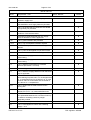
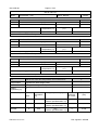
Summary of testing
1. Tests performed on each model.
2. Input test, heating test and some abnormal tests made in a test chamber, which can imitate the most
severe condition in normal use.
Test items particulars:
Serial Number ............................................................... : Prototype samples
Additional information ................................................... : N(.A.)
....................................................................................... :
....................................................................................... :
Test case verdicts
Test case does not apply to the test object.................. : N(.A.)
Test item does meet the requirement .......................... : P(ass)
Test item does not meet the requirement .................... : F(ail)
Testing
Date of receipt of test item ........................................... : 2005-04-04
Date(s) of performance of test...................................... : 2005-04-04—2005-04-10
General remarks
This report is not valid as a CB Test Report unless signed by an approved CB Testing Laboratory and
appended to a CB Test Certificate issued by an NCB in accordance with IECEE 02.
The test results presented in this report relate only to the item tested.
This test report shall not be reproduced except in full, without the written approval of the issuing testing laboratory.
Clause numbers between brackets refer to clauses in IEC 60335-1
"(see Enclosure #)" refers to an additional information appended to the report.
"(see appended table)" refers to a table appended to the report.
Throughout this report a comma is used as the decimal separator.
TRF No:I60335240C
TRF originator: AENOR
12011466 001
Page 3 of 54
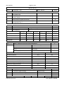
General product information:
•
The appliances are indoor unit only, the indoor unit is a wall mounted type air conditioner, which is
usually not accessible except for maintenance purpose. It will be mounted on the wall at a height of
min. 2,3 m above floor level;
•
The unit is supplied by power cord with plug.
•
The test was performed with a connection to representative outdoor unit;
•
The equipment is equipped with an infrared wireless battery powered remote control unit.
Model type description:
Difference between models:
The model WNG25 DCI is identical with model WNG35 DCI except that:
-
The size of heating exchanger, by which, different cooling and heating capacity are achieved.
-
External size is different.
The model WNG50 DCI is identical with model WNG60 DCI except that:
-
The size of heating exchanger, by which, different cooling and heating capacity are achieved.
-
External size is different.
Difference between models WNG25 DCI, WNG35 DCI and WNG50 DCI, WNG60 DCI:
-
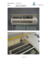
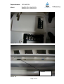
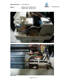
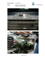
The controller is different, please refer to photo document for details.
-
External size is different.
TRF No:I60335240C
TRF originator: AENOR
12011466 001
Page 4 of 54
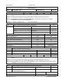
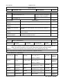
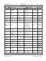
Copy of marking plate:
ELECTRA
MODEL: WNG25 DCI
PROD NO.:
Fuse: 15A(G)*
TYPE:
COSφ=0.97
220-240V~ 50Hz IP20 Rev.A
R-410A:
Prated::32 W
*is applied to single refrigerant circuit only
Cooling capacity: 2500(1400-3600) W *
Heating capacity: 3400(1500-5000) W *
Dehumidification: 1.01 l/h
PS: 6.3MPa
Ps: 0.8MPa
Temp.Class: T1
Weight: 10.5kg
ELECTRA
MODEL: WNG35 DCI
PROD NO.:
Fuse: 15A(G)*
TYPE:
COSφ=0.97
220-240V~ 50Hz IP20
Rev.A
R-410A:
Prated::40 W
*is applied to single refrigerant circuit only
Cooling capacity: 3500(1400-4300) W *
Heating capacity: 4300(1500-5800) W *
Dehumidification: 1.5 l/h
PS: 6.3MPa
Ps: 0.8MPa
Temp. Class: T1
Weight: 10.5kg
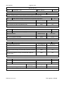
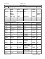
ELECTRA
MODEL: WNG50 DCI
PROD NO.:
Fuse: 20A(G) *
TYPE:
COSφ=0.97
220-240V~ 50Hz IP20 Rev.A
R-410A:
Prated: 56 W
*is applied to single refrigerant circuit only
Cooling capacity: 5000(1500-6000)W *
Heating capacity: 6000(1500-7600)W *
Dehumidification: 2.0 l/h
PS: 6.3MPa
Ps: 0.8MPa
Temp.Class: T1
Weight: 15kg
ELECTRA
MODEL: WNG60 DCI
PROD NO.:
Fuse: 20A(G)*
TYPE:
COSφ=0.97
220-240V~ 50Hz IP20 Rev.A
R-410A:
Prated: 59 W
*is applied to single refrigerant circuit only
Cooling capacity: 6000(1500-6700)W *
Heating capacity: 6500(1800-7900)W *
Dehumidification: 2.0 l/h
PS: 6.3MPa
Ps: 0.8MPa
Temp.Class: T1
Weight: 15kg
TRF No:I60335240C
TRF originator: AENOR
12011466 001
Page 5 of 54
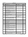
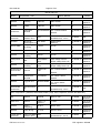
IEC 60 335-2-40
Clause
Requirement - Test
Result - Remark
Verdict
4
GENERAL NOTES ON TESTS
P
Tests performed according to Cl. 4, e.g. nature of
supply, sequence of testing, etc.
P
4.6
Appropriate controls rendered inoperative during the
test (IEC 60335-2-40:1995)
P
4.101
Motor-compressors comply with IEC 60335-2-34
(IEC 60335-2-40:1995)
Indoor unit
N
Motor-compressors subjected to the relevant test
(IEC 60335-2-40:1995)
N
6
CLASSIFICATION
P
6.1
Protection against electric shock: Class I, II, III
Class I
P
6.2
Protection against harmful ingress of water, IP
degree in accordance with IEC 529 (IEC 60335-240:1995)
IP20 (not marked)
P
N
Appliances for outdoor use (IEC 60335-2-40:1995)
Appliances for indoor use (IEC 60335-2-40:1995)
IP20
P
Appliances for laundry rooms (IEC 60335-240:1995)
Warning: “the appliance shall
not be installed in the laundry”
is stated on user manual.
N
6.101
Degree of accessibility (accessible/not accessible to Accessible to general public,
but intended to be technically
the general public (IEC 60335-2-40:1995)
maintained (except for air filter
cleaning) only by qualified
service personnel.
P
7
MARKING
P
7.1
Rated voltage or voltage range (V) ........................ : 220-240V
P
Symbol for nature of supply including number of
phases, unless for single phase operation (IEC
60335-2-40:1995)
~
P
Rated frequency or frequency range (Hz) ............. : 50Hz
P
Rated input or rated current
See rating labels
P
Manufacturer's or responsible vendor's name,
trademark or identification mark
ELECTRA
P
Model or type reference
See rating labels
P
Symbol for Class II
Class I
N
Symbol for degree of protection against ingress of
water, other than IPX0 (IEC 60335-2-40:1995)
IP20 (Not marked)
N
N
Mass of the refrigerant or of each refrigerant in a
blend (except for azeotropic type (IEC 60335-240:1995)
Refrigerant identification (IEC 60335-2-40:1995)
TRF No:I60335240C
R410A
P
TRF originator: AENOR
12011466 001
Page 6 of 54
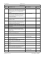
IEC 60 335-2-40
Clause
Requirement - Test
Result - Remark
Verdict
Permissible excessive operating pressure in pascals
for sanitary hot water heat pumps (IEC 60335-240:1995)
7.2
N
Excessive operating pressure of the refrigerant
circuit for suction and discharge, if they differ (IEC
60335-2-40:1995)
See rating labels
P
The maximum operating pressure for the heat
exchanger (IEC 60335-2-40/A1:2000)
See rating labels
P
Separate marking of the appliances with all the
rated characteristics of the supplementary heaters
(IEC 60335-2-40:1995)
N
Marking of the direction of the fluid flow (IEC 603352-40:1995)
N
Warning for stationary appliances
Single supply
N
Warning placed in vicinity of terminal cover
Single supply
N
7.3
Range of rated values correctly marked
Single voltage supply
P
7.4
Voltage setting clearly discernible
Single voltage supply
N
7.5
Marking of rated input for each rated voltage
Single voltage supply
N
Marking for upper and lower limits of rated input
N
7.6
Correct symbols used
P
7.7
Correct connection diagram, fixed to the appliance
7.8
Not for type Z attachment:
- marking of terminals for the neutral conductor (N)
Near the terminal
P
P
Neutral conductor terminal
marked with letter ‘N’.
- marking of earthing terminals
- marking not placed on removable parts
P
P
Marking of earthing terminals is
applied by embossing into
metal.
P
- marking of terminal for single-pole protective
device
P
7.9
Marking or placing of switches which may cause a
hazard
P
7.10
Indications of switches and regulating devices by
use of figures, letters or other
P
The figure 0 indicates only OFF position, unless no
confusion with the OFF position
P
7.11
Indication for direction of adjustment of controls
N
7.12
Instructions for safe use provided
Classification of 6.101 included, for appliances not
accessible to general public (IEC 60335-2-40:1995)
TRF No:I60335240C
Stated in user manual.
P
N
TRF originator: AENOR
12011466 001
Page 7 of 54
IEC 60 335-2-40
Clause
Requirement - Test
7.12.1
Sufficient details for installation or maintenance
supplied:
- national wiring regulations for installation (IEC
60335-2-40:1995)
Result - Remark
Verdict
P
Stated in user manual.
P
- dimensions of space for installation (IEC 60335-2- Stated in user manual.
40:1995)
P
- wiring diagram (IEC 60335-2-40:1995)
P
Provided.
- range of external static pressures (only heat
pumps and appliances with electric resistance
heaters) (IEC 60335-2-40:1995)
N
- minimum clearance from appliances with
supplementary heaters to combustible surfaces
(IEC 60335-2-40:1995)
N
- indication of suitable parts for outdoor use (IEC
60335-2-40:1995)
P
- method of connection to the electrical supply and
interconnection of separate components (IEC
60335-2-40:1995)
P
- type and rated characteristics of fuses (IEC 603352-40:1995)
P
- details of supplementary heating elements,
including fitting instructions (IEC 60335-2-40:1995)
N
- maximum and minimum water or brine operating
temperatures (IEC 60335-2-40:1995)
N
- maximum and minimum water or brine operating
pressures (IEC 60335-2-40:1995)
N
- indication of open water storage tanks (IEC 603352-40:1995)
N
7.12.2
Means for disconnection with contact separation at Power cord with plug
least 3 mm or instruction regarding means of
disconnection in the fixed wiring (IEC 603351/A2:99)
N
7.12.3
Insulation in contact with parts exceeding 50 K;
instruction
N
7.12.4
Information with regard to building-in:
7.12.5
Wall mounted type
N
- dimensions of space
N
- dimensions and position of support
N
- ventilation openings
N
- connection/interconnection plug accessible
N
Replacement cord, type X attachment
N
Replacement cord, type Y attachment
TRF No:I60335240C
Power cord with plug
P
TRF originator: AENOR
12011466 001
Page 8 of 54
IEC 60 335-2-40
Clause
Requirement - Test
Result - Remark
Verdict
Replacement cord, type Z attachment
N
7.13
Instructions and other texts in official language
English
P
7.14
Marking easily legible and durable
P
7.15
Marking on a main part
P
Marking clearly discernible from outside
P
Stationary appliance: name or trademark and model Trademark and model are
or type reference visible after installation
visible.
P
Indication for switches and controls in vicinity of
components; not on removable parts if misleading
P
7.16
Marking of a possible replaceable thermal link or
fuse link clearly visible with regard to replacing the
link
P
7.101
Marking of fuses and overload protective devices, if
replaceable (IEC 60335-2-40:1995):
N
- fuse rated current in amperes, type and rated
voltage (IEC 60335-2-40:1995)
N
- manufacturer and model of the overload protective
device (IEC 60335-2-40:1995)
N
7.102
Marking for connection with aluminium wire, if
necessary (IEC 60335-2-40:1995)
The use of aluminium wires is
not intended.
8
PROTECTION AGAINST ACCESSIBILITY TO
LIVE PARTS
P
8.1
Adequate protection against accidental contact with
live parts
P
8.1.1
All positions; detachable parts removed
See below
N
P
− Installation only by authorized service personnel.
Basic insulation is provided before installation is carried out.
Test finger and test pin applied to all openings after equipment was installed as described in
installation manual.
− Indoor part:
The evaporator is connected to earth, no bare live parts accessible through openings in the
Enclosure.
Removal of lamps: protection against contact with
live parts
8.1.2
No lamps
N
Use of test finger: no contact with live parts
P
Use of test pin: no contact with live parts
P
Test pin applied to openings in earthed metal
enclosures having a coating such as enamel or
lacquer (IEC 60335-1/A2:1999)
P
8.1.3
Use of test probe: no contact with live parts of
visible glowing heating elements
8.1.4
Accessible part not considered live if:
TRF No:I60335240C
No visible glowing heating
elements used.
N
P
TRF originator: AENOR
12011466 001
Page 9 of 54
IEC 60 335-2-40
Clause
Requirement - Test
Result - Remark
Verdict
-.extra-low a.c. voltage: peak values not exceeding
42,4 V
- extra-low d.c. voltage: not exceeding 42,4 V
N
Remote controller
P
- or separated from live parts by protective
impedance, d.c. current not exceeding 2 mA
N
- or separated from live parts by protective
impedance, a.c. peak value not exceeding 0,7 mA
N
- for peak value 42,4 V up to and including 450 V
capacitance not exceeding 0,1 µF
N
- for peak value 450 V up to and including 15 kV
capacitance not exceeding 0,1 µF
N
Live parts protected at least by basic insulation
before installation or assembly:
P
- built-in appliances
N
- fixed appliances
P
- separate units
N
8.2
Class II appliances and constructions adequately
protected against accidental contact with basic
insulation and metal parts separated from live parts
with only basic insulation
P
10
POWER INPUT AND CURRENT
P
10.1
Power input at rated voltage and normal operating (see appended table)
temperature not deviating from rated input by more
than shown in table; measured power input (W);
rated input (W); deviation: .......................................
P
10.2
Current at normal operating temperature not
Not marked on rating label
deviating from rated current by more than shown in
table; measured current at rated voltage under
normal operation (A); rated current (A); deviation . :
N
11
HEATING
P
11.1
No excessive temperatures in normal use
P
Compliance is checked by the tests of Annex C, if
(IEC 60335-2-40:1995):
N
- temperature of motor winding exceeds values
shown in Table 3 (IEC 60335-2-40:1995)
N
8.1.5
- there is no doubt about the classification of the
insulation system of the motor (IEC 60335-240:1995)
11.2
Placing and mounting of appliance (IEC 60335-240:1995):
TRF No:I60335240C
The insulation material used in
the motors is UL approved.
N
P
TRF originator: AENOR
12011466 001
Page 10 of 54
IEC 60 335-2-40
Clause
Requirement - Test
Result - Remark
Verdict
- clearances to adjacent surfaces (IEC 60335-240:1995)
P
- static pressures, (IEC 60335-2-40:1995) except for
fan coils where the flow rates and liquid
temperatures, that shall be the maximum specified
in the manufacturer’s instruction (IEC 60335-240:1995+A1:2000)
P
- adjustable limit controls set at the maximum cutout setting and the minimum differential (IEC 603352-40:1995)
P
- flows (IEC 60335-2-40:1995)
P
For appliances with supplementary heaters, use test
casing of 11.9 (IEC 60335-2-40:1995)
N
For appliances with supplementary heaters, an inlet
duct is connected to the inlet air opening (IEC
60335-2-40:1995)
N
Air outlet duct if necessary (IEC 60335-2-40:1995)
N
11.3
Temperature rises determined by thermocouples or
resistance method
P
11.4
Test performed at supply voltage between 0,94 and 254V is considered as the more
1,06 times the rated voltage (IEC 60335-2-40:1995) severe voltage.
P
Heating appliances operated under normal
operation at 1,15 times rated power input
N
Test conducted in the heating mode and in the
cooling mode, if both exist (IEC 60335-2-40:1995)
P
All the supplementary heating elements operative
simultaneously (IEC 60335-2-40:1995)
N
11.5
Indoor unit
N
11.6
Defrost test in the most unfavourable conditions, if
needed (IEC 60335-2-40:1995)
11.7
Appliances operated continuously until steady
conditions except for defrost tests (IEC 60335-240:1995)
P
11.8
Monitored temperatures not exceeding the values of (see appended table)
Table 3 (IEC 60335-2-40:1995)
P
Protective devices do not operate
P
Sealing compound not flowing out
P
Temperature of the air in the outlet duct not
exceeding 90 °C (IEC 60335-2-40:1995)
N
Test casing and installation of the rest of the
appliances in accordance with the manufacturer's
instructions (IEC 60335-2-40:1995)
P
11.9
TRF No:I60335240C
TRF originator: AENOR
12011466 001
Page 11 of 54
IEC 60 335-2-40
Clause
Requirement - Test
Result - Remark
Verdict
Glass fibre insulation for appliances without
indication of minimum clearances according to the
manufacturer; thermocouple in contact with the
enclosure (IEC 60335-2-40:1995)
N
13
LEAKAGE CURRENT
P
13.1
Leakage current not excessive and electric strength
adequate
P
13.2
Leakage current measured by means of circuit
described in Annex G (IEC 60335-2-40:1995)
P
13.3
Leakage current measurements
(see appended table)
P
Electric strength test of insulation. See Note in
Interpretation Sheet I-SH 02, August 1994
(see appended table)
P
No breakdown during the test
P
15
MOISTURE RESISTANCE
P
15.1
Enclosure provides the degree of moisture
protection against the ingress of water (rain,
overflow from the drain pan of defrosting, tests of
15.2, 15.3, 11.6 and Cl. 16) (IEC 60335-2-40:1995)
P
Motor-compressor not operated and detachable
parts not removed during 15.2 and 15.3 (IEC
60335-2-40/A1:2000)
N
After test, water inside the enclosure has not
reduced the creepage distances and clearances
below the values of Cl. 29 (IEC 60335-2-40:1995)
P
15.2
Tests in accordance with IEC 529 in appliances
other than IPX0, as specified (IEC 60335-240:1995)
15.3
Spillage of liquid does not affect the electrical
insulation (IEC 60335-2-40:1995)
N
15.4
Spillage test according to IEC 60335-2-40/A1:2000
P
16
LEAKAGE CURRENT AND ELECTRIC
STRENGTH
P
16.1
No excessive leakage current and adequate
insulation and electric strength (tests 16.2 and 16.3)
P
16.2
Leakage current measurements (IEC 60335-240:1995)
(see appended table)
P
16.3
Electric strength tests (values in table 5). See Note
in Interpretation Sheet I-SH 02, August 1994
(see appended table)
P
17
OVERLOAD PROTECTION OF TRANSFORMERS
AND ASSOCIATED CIRCUITS
TRF No:I60335240C
IP20
N
P
TRF originator: AENOR
12011466 001
Page 12 of 54
IEC 60 335-2-40
Clause
Requirement - Test
Result - Remark
Verdict
No excessive temperatures in transformer or
associated circuits in event of short-circuits likely to
occur in normal use
Appliance supplied with 1,06 or 0,94 times rated
voltage and the most unfavourable short-circuit or
overload likely to occur in normal use applied
P
(see appended table)
P
Temperature rise of insulation of the conductors of
safety extra-low voltage circuits not exceeding the
relevant value specified in table 3 by more than
15 K
N
Temperature of the winding not exceeding the value (see appended table)
specified in table 6
P
Except fail-safe transformer complying 15.5 of IEC
61558-1 (IEC 60335-1/A2:1999)
N
Not fail-safe transformer
19
ABNORMAL OPERATION
P
19.1
The risk of fire or mechanical damage or electric
shock under abnormal or careless operation
obviated (tests 19.2-19.14) (IEC 60335-2-40:1995)
P
Electronic circuits so designed and applied that a
fault will not render the appliance unsafe (electric
shock, fire or mechanical hazard, dangerous
malfunction (test 19.11 and 19.12) (IEC 60335-240:1995)
P
Test of appliance with motor rotors, other than
(see appended table)
motor-compressors, operated for 15 days (360 h) or
until a protection device opens the circuit (IEC
60335-2-40:1995)
P
Insulation of motor windings (IEC 60335-2-40:1995) (see appended table)
................................................................................. :
P
Temperature of enclosure does not exceed (°C)
(see appended table)
(IEC 60335-2-40:1995) .......................................... :
P
Temperature of the windings does not exceed the
values shown in the table; temperature (°C) (IEC
60335-2-40:1995) ................................................... :
P
Electric strength test as specified in 16.3, 72 h after
the beginning of the test (IEC 60335-2-40:1995)
P
A 30 mA residual current device does not open (IEC
60335-2-40:1995)
P
At the end, the leakage current between the
windings and the enclosure does not exceed 2 mA
(IEC 60335-2-40:1995)
P
Motor-compressor complies with IEC 60335-2-34
(IEC 60335-2-40:1995) .......................................... :
N
19.2
19.3
TRF No:I60335240C
TRF originator: AENOR
12011466 001
Page 13 of 54
IEC 60 335-2-40
Clause
Requirement - Test
Result - Remark
Verdict
Test of the motor-compressor with the rotor locked
as specified in 19.3 of IEC 60335-2-34 (IEC 603352-40:1995)
N
19.4
Test of three-phase motors operated under the
conditions of Cl. 11 with one phase disconnected
until steady conditions (IEC 60335-2-40:1995)
N
19.5
Test of appliance with heat transfer medium flow of
the outdoor heat exchanger restricted or shut off
when reaching steady conditions (IEC 60335-240:1995)
N
Test of appliance with heat transfer flow of the
indoor heat exchanger restricted or shut off when
reaching steady conditions (IEC 60335-2-40:1995)
P
Disconnection of the motor common to both the
outdoor and the indoor heat exchangers when
reaching steady conditions (IEC 60335-2-40:1995)
N
19.6
Test of appliances using water as heat transfer
medium (IEC 60335-2-40:1995)
N
19.7
The test of air to air appliances at rated voltage or at 11°C
the upper limit of the rated voltage range. The drybulb temperature is 5 K below the values specified
by the manufacturer (IEC 60335-2-40:1995)
P
Test with the dry-bulb temperature 10 K over the
42°C
values specified by the manufacturer (IEC 60335-240:1995)
P
19.8
Test of appliances with supplementary electric
heaters (IEC 60335-2-40:1995)
N
19.9
Test at a temperature permitting continuous
operation of the motor-compressor and the electric
heating elements at the same time (IEC 60335-240:1995)
P
19.10
Test of the appliance with any defect which may be Open circuiting and shortexpected during normal use (IEC 60335-2-40:1995) circuiting of motor capacitor
performed, and no hazards
occurred.
P
19.11
Electronic circuits, compliance checked by
evaluation of the fault conditions specified in 19.11.2
for all circuits or parts of circuits, unless they comply
with the conditions specified in 19.11.1
P
Windings temperature not exceeding values shown
in Table 6 (IEC 60335-2-40:1995)
P
Appliance shall comply with the conditions of 19.14
(IEC 60335-2-40:1995)
P
TRF No:I60335240C
No heating element
TRF originator: AENOR
12011466 001
Page 14 of 54
IEC 60 335-2-40
Clause
19.11.1
19.11.2
Requirement - Test
Result - Remark
Verdict
Appliance withstands the test: a conductor becomes
open circuited and three conditions are met (IEC
60335-2-40:1995)
P
Before applying the fault conditions a) to f) in
19.11.2, it is checked if circuits or parts of circuit
meet both of the following conditions:
P
- the electronic circuit is a low-power circuit, that is,
the maximum power at low-power points does not
exceed 15 W according to the tests specified
N
- the protection against electric shock, fire hazard,
mechanical hazard or dangerous malfunction in
other parts of the appliance does not rely on the
correct functioning of the electronic circuit
N
Fault conditions applied one at a time, the appliance (see appended table)
operated under conditions specified in Cl. 11, but
supplied at rated voltage, the duration of the tests
as specified:
P
a) short circuit of creepage distances and
The Cl/Cr distances are not less
clearances between live parts of different potential, than the valves specified in
if these distances are less than the values specified 29.1.
in 29.1, unless the relevant part is adequately
encapsulated
N
b) open circuit at the terminals of any component
(see appended table)
P
c) short circuit of capacitors, unless they comply
with IEC 60384-14 or 14.2 of IEC 60065
(see appended table)
P
d) short circuit of any two terminals of an electronic
component, other than integrated circuits. This fault
condition is not applied between the circuits of an
optocoupler
P
e) failure of triacs in the diode mode
N
f) failure of an integrated circuit. In this case the
possible hazardous situations of the appliance are
assessed to ensure that safety does not rely on the
correct functioning of such a component
N
Short-circuit of low-power circuits (IEC 60335-240:1995)
N
The duration of the tests (IEC 60335-2-40:1995):
P
- as specified in 11.7 but only for one operating
cycle (in case the fault cannot be recognised by
user) IEC 60335-2-40:1995)
P
- as specified in 19.2, if fault can be recognised by
user (IEC 60335-2-40:1995)
P
- until steady conditions are established (IEC 603352-40:1995)
P
TRF No:I60335240C
TRF originator: AENOR
12011466 001
Page 15 of 54
IEC 60 335-2-40
Clause
19.12
19.13
19.14
Requirement - Test
Verdict
Test ended if interruption of supply occurs within the
appliance (IEC 60335-2-40:1995)
P
Fault condition f) applied to encapsulated or similar
components (IEC 60335-2-40:1995)
N
PTC's, NTC's and VDR's resistors not shortcircuited if used as specified by manufacturer (IEC
60335-2-40:1995)
N
If the safety of the appliance for any of the fault
conditions specified in 19.11.2 depends on the
operation of a miniature fuse-link complying with
IEC 127, the test is repeated but with fuse-link
replaced by an ammeter (IEC 60335-2-40:1995)
Fuse-link not operated during
19.11 tests.
N
Current ≤ 2,1 times rated current of fuse-link, circuit
not adequately protected (fuse-link short-circuited)
(IEC-335-2-40:95)
N
Current ≥ 2,75 times rated current of fuse-link,
circuit adequately protected (IEC 60335-2-40:1995)
N
Current ≥ 2,1 and I ≤ 2,75 times rated current, fuselink short-circuited and test carried out during
specified time (IEC 60335-2-40:1995)
N
During the tests the appliance does not emit flames,
molten metal, poisonous or ignitable gas in
hazardous amounts
P
Test for appliances with PTC heating elements (IEC
60335-2-40:1995)
N
No flames, molten metal, poisonous or ignitable gas
or deformed enclosures (IEC 60335-2-40:1995)
P
Temperatures rise shall not exceed the values
shown in Table 7 (IEC 60335-2-40:1995)
19.15
Result - Remark
The temperature rise of test
corner, sheath of supply cord
are lower than 175°C
P
The electric strength test, the test voltage being:
P
- basic insulation: 1000 V
P
- supplementary insulation: 2750 V
P
- reinforced insulation: 3750 V
P
Appliance with supplementary heaters and free air
discharge subjected to the additional tests of (IEC
60335-2-40/A1:2000)
N
Appliance operated under conditions of clause 11
with temperature controls shorts-circuited and
appliance covered as required (IEC 60335-2-40/A1:
2000)
P
During the test the temperature rise not exceed
150°C (IEC 60335-2-40/A1: 2000)
P
TRF No:I60335240C
TRF originator: AENOR
12011466 001
Page 16 of 54
IEC 60 335-2-40
Clause
Requirement - Test
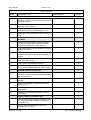
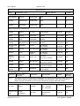
20
STABILITY AND MECHANICAL HAZARDS
20.1
Adequate stability
Result - Remark
Verdict
P
Fixed to the wall
P
Tilting test through an angle of 10 ° (appliance
placed on an inclined plane/horizontal plane);
appliance does not overturn
N
Tilting test repeated on appliances with heating
elements, angle of inclination increased to 15 °
N
Possible heating test in overturned position;
temperature rise does not exceed values shown in
Table 7
N
Moving parts adequately arranged or enclosed as to Indoor unit: installed 2,3m
above the ground
provide protection against personal injury
P
Protective enclosures, guards and similar parts are
non-detachable
P
Adequate mechanical strength and fixing of
protective enclosures
P
Self-resetting thermal cut-outs and overcurrent
protective devices not causing a hazard, if
unexpectedly reclosed
P
Not possible to touch dangerous moving parts with
test finger
P
MECHANICAL STRENGTH
P
Appliance has adequate mechanical strength and is
constructed as to withstand rough handling (safety
requirements of ISO 5149 apply, IEC 60335-240:1995)
P
No damage after three blows applied to various
parts of the enclosure, impact energy 0,5 ± 0,04 Nm
P
If necessary, supplementary or reinforced insulation
subjected to the electric strength test of 16.3
P
If necessary, repetition of groups of three blows on
a new sample
N
22
CONSTRUCTION
P
22.1
Appliance marked with the first numeral of the IP
system: relevant requirements of IEC 529 are
fulfilled
22.2
Stationary appliance: means to provide all-pole
disconnection from the supply provided, the
following means being available:
P
- a supply cord fitted with a plug
P
- a switch complying with 24.3
N
20.2
21
TRF No:I60335240C
IP20 (not marked).
P
TRF originator: AENOR
12011466 001
Page 17 of 54
IEC 60 335-2-40
Clause
Requirement - Test
Result - Remark
Verdict
- a statement in the instruction sheet that a
disconnection incorporated in the fixed wiring is to
be provided
N
- an appliance coupler
N
Single-phase Class I appliance with heating
elements, intended to be permanently connected to
fixed wiring, incorporating single-pole switches or
single-pole protective devices for the disconnection
of the heating element(s): the switches/devices
being connected in the phase conductor
N
Appliance provided with pins: no undue strain on
socket-outlets
N
Applied torque not exceeding 0,25 Nm
N
22.4
Appliance for heating liquids and appliance causing
undue vibration not provided with pins for insertion
into socket-outlets
N
22.5
No risk of electric shock when touching the pins of
the plug
N
22.6
Electrical insulation not affected by condensing
water or leaking liquid
P
Electrical insulation of Class II appliances not
affected in case of a hose rupture or seal leak
N
Indoor unit.
Electrical insulation not affected by snow
penetration to the appliance enclosure (IEC 603352-40:1995)
N
22.7
Adequate safeguards against the risk of excessive
pressure in appliances provided with steamproducing devices
N
22.8
Electrical connections not subject to pulling during
cleaning of compartments to which access can be
gained without the aid of a tool, and which are likely
to be cleaned in normal use
P
22.9
Insulation, internal wiring, windings, commutators
and slip rings not exposed to oil, grease or similar
substances
P
Adequate insulating properties of oil or grease to
which insulation is exposed
P
22.3
22.10
Location or protection of reset buttons of non-selfresetting controls is so that accidental resetting is
unlikely
TRF No:I60335240C
No over-pressure expected,
which could lead to a
hazardous situation.
Refrigerant circuit is intrinsic
pressure safe according to ISO
5149. See also clause 21.
No non-self-resetting controls
employed
N
TRF originator: AENOR
12011466 001
Page 18 of 54
IEC 60 335-2-40
Clause
Requirement - Test
22.11
Reliable fixing of non-detachable parts which
provide the necessary degree of protection against
electric shock, moisture or contact with moving parts
P
Obvious locked position of snap-in devices used for
fixing such parts
N
No deterioration of the fixing properties of snap-in
devices used in parts which are likely to be removed
during installation or servicing
N
Tests
N
Handles, knobs etc. fixed in a reliable manner
N
Fixing in wrong position of handles, knobs etc.
indicating position of switches or similar
components not possible
N
Axial force 15 N applied to parts, the shape of which
being so that an axial pull is unlikely to be applied
N
Axial force 30 N applied to parts, the shape of which
being so that an axial pull is likely to be applied
N
22.13
Unlikely that handles, when gripped as in normal
use, make the operators hand touch parts having a
temperature rise exceeding the value specified for
handles which are held for short periods only
N
22.14
No ragged or sharp edges creating a hazard for the No sharp edges. Corners are
well rounded.
user in normal use, or during user maintenance
P
22.12
No exposed pointed ends of self tapping screws
etc., liable to be touched by the user in normal use
or during user maintenance
22.15
Storage hooks and the like for flexible cords smooth
and well rounded
22.16
Automatic cord reels cause no undue abrasion or
damage to the sheath of the flexible cord, no
breakage of conductors strands, no undue wear of
contacts
Result - Remark
Verdict
Checked
P
N
No automatic cord reels
N
Cord reel tested with 6000 operations, as specified
N
Electric strength test of 16.3, voltage of 1000 V
applied
N
22.17
Spacers not removable from the outside by hand or No spacers
by means of a screwdriver or a spanner
N
22.18
Current-carrying parts and other metal parts
resistant to corrosion under normal conditions of
use
P
22.19
Driving belts not used as electrical insulation
N
TRF No:I60335240C
TRF originator: AENOR
12011466 001
Page 19 of 54
IEC 60 335-2-40
Clause
Requirement - Test
22.20
Direct contact between live parts and thermal
insulation effectively prevented, unless material
used is non-corrosive, non-hygroscopic and noncombustible
22.21
Wood, cotton, silk, ordinary paper and fibrous or
hygroscopic material used as insulation, unless
impregnated
22.22
Asbestos not used in the construction of the
appliance
P
Asbestos is used, but the liberation of dust of
impregnated asbestos or of asbestos fibres into the
surrounding air adequately prevented
N
22.23
Oils containing polychlorinated biphenyl (PCB) not
used
P
22.24
Bare heating elements adequately supported to
No bare heating elements
prevent contact with accessible metal parts in case employed.
of rupture or sagging (IEC 60335-2-40:1995)
N
Bare heating elements only used with metal
enclosures (wood or composite enclosures not
allowed) (IEC 60335-2-40:1995)
N
22.25
Sagging heating conductors cannot come into
contact with accessible metal parts
N
22.26
No SELV circuits employed
The insulation between parts operating at safety
extra-low voltage and other live parts complies with
the requirements for double or reinforced insulation
N
22.27
Parts connected by protective impedance separated
by double or reinforced insulation
P
22.28
Metal parts of Class II appliances conductively
connected to gas pipes or in contact with water:
separated from live parts by double or reinforced
insulation
Class I appliances
N
22.29
Class II appliances permanently connected to fixed Class I appliances
wiring so constructed that the required degree of
protection against electric shock is maintained after
installation
N
22.30
Parts serving as supplementary or reinforced
insulation fixed so that they cannot be removed
without being seriously damaged, or
P
So constructed that they cannot be replaced in an
incorrect position, and so that if they are omitted,
the appliance is rendered inoperable or manifestly
incomplete
P
TRF No:I60335240C
Result - Remark
Verdict
N
No such materials used as
insulator
N
TRF originator: AENOR
12011466 001
Page 20 of 54
IEC 60 335-2-40
Clause
Requirement - Test
22.31
Creepage distances and clearances over
supplementary and reinforced insulation not
reduced below values specified in 29.1 as a result of
wear
P
Creepage distances and clearances over
supplementary or reinforced insulation not reduced
to less than 50% of values specified in 29.1 if wires,
screws etc. becomes loose
P
Supplementary and reinforced insulation designed
or protected against deposition of dirt or dust
P
Ceramic material not tightly sintered, similar
material or beads alone not used as supplementary
or reinforced insulation
P
Supplementary insulation of natural or synthetic
rubber resistant to ageing, or arranged and
dimensioned so that creepage distances are not
reduced below values specified in 29.1
N
Oxygen bomb test at 70 °C for 96 h and 16 h at
room temperature
N
See Note ("In case of doubt") (IEC 603351/A2:1999)
N
22.32
22.33
Result - Remark
Verdict
Conductive liquids which are or may become
accessible in normal use are not in direct contact
with live parts
Checked by clause 15
P
Conductive liquids are not in direct contact with
basic insulation or reinforced insulation in Class II
constructions
Condensing water cannot
become in contact with basic
or reinforced insulation
P
Conductive liquids in contact with live parts, not in
direct contact with reinforced insulation in class II
construction (IEC 60335-1/A2:1999)
N
22.34
Shafts of operating knobs, handles, levers etc. not
live, unless the shaft is not accessible when the part
is removed
N
22.35
Handles, levers and knobs, held or actuated in
normal use, not becoming live in the event of an
insulation fault
N
Such parts being of metal, and their shafts or fixings
are likely to become live in the event of an insulation
fault, they are either adequately covered by
insulation material, or their accessible parts are
separated from their shafts or fixings by
supplementary insulation
N
TRF No:I60335240C
TRF originator: AENOR
12011466 001
Page 21 of 54
IEC 60 335-2-40
Clause
Requirement - Test
Result - Remark
Verdict
This requirement does not apply to handles, levers
and knobs on stationary appliances other than those
of electrical components, provided they are either
reliably connected to an earthing terminal or
earthing contact, or separated from live parts by
earthed metal
N
22.36
Handles continuously held in the hand in normal use No handles, which are
are so constructed that when gripped as in normal continuously held.
use, the operators hand is not likely to touch metal
parts, unless they are separated from live parts by
double or reinforced insulation
N
22.37
Capacitors in Class II appliances not connected to Class I appliance. However,
accessible metal parts, unless complying with 22.42 capacitors are separated from
accessible metal parts by
double or reinforced insulation.
N
Metal casings of capacitors in Class II appliances
separated from accessible metal parts by
supplementary insulation, unless complying with
22.42
N
22.38
Capacitors not connected between the contacts of a
thermal cut-out
P
22.39
Lamp holders only used for the connection of lamps No lamp holder employed
N
22.40
Motor-operated appliances and combined
appliances, intended to be moved while in
operation, are fitted with a switch to control the
motor
Fixed appliance.
N
22.41
Mercury switches mounted according to the
requirement
Mercury switches not
employed.
N
22.42
Protective impedance consisting of at least two
separate components
P
Values specified in 8.1.4 not exceeded if any one of
the components is short-circuited or open-circuited
P
22.43
Appliances adjustable for different voltages,
accidental changing of the setting of the voltage
unlikely to occur
22.44
Appliances shall not have an enclosure likely to be
treated as a toy by children (IEC 60335-1/A2:1999 )
P
22.101
Appliances intended to be fixed, securely fixed (IEC
60335-2-40:1995)
P
22.102
Double thermal cut-out in appliances with
supplementary heating elements (the first one shall
be a self-resetting and the other a non-self-resetting
thermal cut-out) (IEC 60335-2-40:1995)
N
TRF No:I60335240C
Single supply voltage
P
TRF originator: AENOR
12011466 001
Page 22 of 54
IEC 60 335-2-40
Clause
Requirement - Test
Result - Remark
Verdict
Thermal cut-outs of the capillary type open in the
event of leakage of the capillary tube (IEC 60335-240:1995)
N
Thermal cut-outs comply with 24.3 (switches) (IEC
60335-2-40:1995)
N
Thermal cut-outs operating in Cl. 19. Shall be of the
non-self-resetting type (IEC 60335-2-40:1995)
N
22.103
Non-self-resetting cut-outs independent of other
control devices (IEC 60335-2-40:1995)
N
22.104
Containers of sanitary hot water heat pumps
withstand twice the permissible pressure in closed
containers or 0,15 MPa in open containers, without
leakage or rupture (IEC 60335-2-40:1995)
N
22.105
Air or vapour cushion in closed containers not
exceeding the 10% (IEC 60335-2-40:1995)
N
22.106
Pressure relief devices operating at 0,1 MPa over
the permissible pressure (IEC 60335-2-40:1995)
N
22.107
Water outlet systems of open containers free from
obstructions causing over-pressure (IEC 60335-240:1995)
N
Vented containers of sanitary hot water heat pumps
always open to the atmosphere through appropriate
aperture (IEC 60335-2-40:1995)
N
22.108
Not vented open containers are subjected to a test
in accordance with 22.104 to a vacuum of 33 kPa
for 15 min (IEC 60335-2-40:1995)
N
22.109
Replacement of non-self-resetting thermal cut-outs
does not damage other connections (IEC 60335-240:1995)
N
22.110
Non-self-resetting thermal cut-outs operate without
short-circuiting live parts of different potential and
without causing contact between live parts and the
enclosure (IEC 60335-2-40:1995)
N
Test repeated five times without blowing a 3 A fuse
which connects the appliance to earth (IEC 603352-40:1995)
N
Electric strength test as specified in 16.3 for
supplementary heating elements (IEC 60335-240:1995)
N
22.111
Manual resetting of thermostats not necessary after
power supply interruption (IEC 60335-2-40:1995)
P
23
INTERNAL WIRING
P
TRF No:I60335240C
TRF originator: AENOR
12011466 001
Page 23 of 54
IEC 60 335-2-40
Clause
Requirement - Test
Result - Remark
Verdict
23.1
Wireways smooth and free from sharp edges
Self-tapping screw cannot
damage wires. Wires are kept
away by fixing with cable ties.
Wires close the sharp edges
of the blades are kept away
by cable ties.
Wires protected against contact with burrs, cooling
fins etc.
Wire holes in metal well rounded or provided with
bushings
P
P
Without wire hole in metal part
N
Wiring effectively prevented from coming into
contact with moving parts
P
Beads etc. on live wires cannot change their
position, and are not resting on sharp edges or
corners
N
Beads inside flexible metal conduits contained
within an insulating sleeve
N
Electrical connections and internal conductors
wiring movable relatively to each other not exposed
to undue stress
N
Flexible metallic tubes not causing damage to
insulation of conductors
N
Open-coil springs not used
N
Adequate insulating lining provided inside a coiled
spring, the turns of which touch one another
N
No damage after 10 000 flexings
N
Electric strength test, 1000 V between live parts and
metal parts
N
23.4
Bare internal wiring sufficiently rigid and fixed
P
23.5
The basic insulation of internal wiring withstanding
the electrical stress likely to occur in normal use
P
No breakdown when a voltage of 2000 V is applied
for 15 min between the conductor and metal foil
wrapped around the insulation
P
23.6
Sleeving used as supplementary insulation on
internal wiring retained in position by positive means
P
23.7
Only the colour combination green/yellow used for
earthing conductors
P
23.8
Aluminium wires not used for internal wiring
N
23.9
No lead-tin soldering of stranded conductors where
they are subject to contact pressure, unless
P
clamping means so constructed that there is no risk
of bad contact due to cold flow of the solder
P
23.2
23.3
TRF No:I60335240C
TRF originator: AENOR
12011466 001
Page 24 of 54
IEC 60 335-2-40
Clause
Requirement - Test
24
COMPONENTS
24.1
Components comply with safety requirements in
relevant IEC standards
24.1.1
Result - Remark
Verdict
P
Respective safety relevant
components complying with
international standards or
equivalent national version.
P
Motor-compressors not tested according to IEC
60335-2-34 (not necessary to meet all requirements
of IEC 60335-2-34) (IEC 60335-2-40:1995)
N
Fixed capacitors for radio interference suppression,
compliance with annex Q (IEC 60335-1/A2:1999)
P
Small lampholders: compliance with requirements
for E10 lampholders
No lampholders employed.
N
Isolating transformers and safety isolating
transformers: compliance with IEC 61558-2-6 or
comply with annex R (IEC 60335-1/A2:1999)
P
Appliance couplers for IPx0 appliances: compliance
with IEC 60320
N
Other appliance couplers: compliance with IEC 309
N
Automatic controls: compliance with IEC 60730,
unless tested with the appliance
Thermal cutouts are approved
type.
P
Switches: compliance with IEC 61058-1, unless
tested with the appliance (IEC 60335-1/A2:1999)
P
24.1.2
Automatic controls complying with IEC 60730:
additional tests according to this standard and
11.3.5 to 11.3.8 and Cl. 17 of IEC 60730 as type 1
controls (see number of cycles of operation IEC
60335-2-40:1995)
N
24.1.3
Switches tested under the conditions occurring in
the appliance, comply with annex S (IEC 603351/A2: 1999)
N
Switch tested separately according to IEC 610581for 10 000 cycles of operation (IEC 603351/A2:1999)
N
Switches for no-load-operation and operable only
with the aid of a tool, are not subjected to the tests
of clauses of IEC 61058-1 This applies also to
switches operated by hand, and with interlock for
no-load-operation (IEC 60335-1/A2: 1999)
N
Switches without this interlock subjected to the test
of Cl. 17.2.7 for 100 cycles of operation (IEC 603351/A2: 1999)
N
Components marked with their operating
characteristics are used in the appliance in
accordance with these markings
P
24.1.4
TRF No:I60335240C
TRF originator: AENOR
12011466 001
Page 25 of 54
IEC 60 335-2-40
Clause
24.1.5
Requirement - Test
Result - Remark
Verdict
Component which have to comply with other
standard is tested separately, according to the
relevant standard
P
Component used within the limits of its marking,
tested in accordance with conditions occurring in the
appliance
P
Component not marked, or not used in accordance
with its marking, or no IEC standard exists, tested
under the conditions occurring in the appliance
P
Components not mentioned in table 3 tested as part
of the appliance
P
Voltage across capacitors in series with a motor
winding does not exceed 1,1 times rated voltage,
when the appliance is supplied at 1,1 times rated
voltage under minimum load
All samples measured at 264V
and the highest value was
listed:
Indoor fan capacitor: 196V
Capacitors for which 30.2.3. is applicable and
permanently connected in series with a motor shall
be class P1 or P2 of IEC 60252 (IEC 603351/A2:1999)
List of components
24.2
P
P
(see appended table)
P
No switches or automatic controls in flexible cords
P
No devices causing the protective device in the
fixed wiring to operate in the event of a fault in the
appliance
P
No thermal cut-outs which can be reset by soldering
P
24.3
Switch intended for all-pole disconnection of
stationary appliances is directly connected to the
supply terminals, having a contact separation of at
least 3 mm in each pole
Stated in user manual.
P
24.4
Plugs and socket-outlets for heating elements and
extra-low voltage circuits, not interchangeable with
plugs and
No extra-low voltage circuits.
N
Socket-outlets or with connectors and appliance
inlets complying with IEC 60083, IEC 60906-1 or
IEC 60320, respectively
N
24.5
Plugs and socket-outlets etc. for interconnection
cords, not interchangeable with plugs and socketoutlets or connectors and appliance inlets complying
with IEC 60083 and IEC 60906-1 or IEC 60320,
respectively, if direct supply from the mains could
give rise to a hazard
N
24.6
Motors connected to the supply mains and having
inadequate basic insulation for the rated voltage of
the appliance, comply with the requirements of
Annex F
N
TRF No:I60335240C
TRF originator: AENOR
12011466 001
Page 26 of 54
IEC 60 335-2-40
Clause
Requirement - Test
Result - Remark
Verdict
The components are listed on an appended table
N
24.101
Replaceable parts of thermal control devices
identified by marking (IEC 60335-2-40:1995)
N
25
SUPPLY CONNECTION AND EXTERNAL
FLEXIBLE CORDS
P
25.1
For connection to the supply, a supply cord fitted
with a plug may be provided, if (IEC 60335-240:1995):
P
- the appliance is only for indoor use (IEC 60335-240:1995)
P
- it is marked with a rating of 25 A or less (IEC
60335-2-40:1995)
N
- it complies with the code requirements of the
country where it will be used (IEC 60335-2-40:1995)
P
- pins for insertion into socket-outlets provided for
connection to the supply (IEC 60335-2-40:1995)
N
- appliance inlet not allowed (IEC 60335-2-40:1995)
N
Appliance not provided with more than one means
of connection to the supply
P
Stationary appliance for multiple supply may be
provided with more than one means of connection,
provided electric strength test of 1250 V for 1 min
between each means of connection causes no
breakdown
N
Connection of supply wires for appliance intended to
be permanently connected to fixed wiring possible
after the appliance has been fixed to its support
N
Appliance provided with a set of terminals for the
connection of cables or fixed wiring, cross-sectional
areas specified in 26.3
N
Appliance provided with a set of terminals allowing
the connection of a flexible cord
N
Appliance provided with a set of supply leads
accommodated in a suitable compartment
N
Appliance provided with a set of terminals and cable
entries, conduit entries, knock-outs or glands,
allowing connection of appropriate type of cable or
conduit
N
Cable and conduit entries, rated current of
appliance not exceeding 16 A, dimension according
to table 8
N
25.2
25.3
25.4
TRF No:I60335240C
TRF originator: AENOR
12011466 001
Page 27 of 54
IEC 60 335-2-40
Clause
25.5
Requirement - Test
Result - Remark
Verdict
Introduction of conduit or cable does not affect the
protection against electric shock or reduce creepage
distances and clearances below values specified in
29.1
N
Method for assemble supply cord with the
appliance:
N
- type X attachment
N
- type Y attachment
Power cord with plug.
P
- type Z attachment, if allowed in part 2
N
Type X attachment: specially prepared cord
N
Type X attachment not used for flat twin tinsel cord
N
25.6
Plugs fitted with only one flexible cord
P
25.7
Appliance supply cord not lighter than:
P
- braided cord (245 IEC 51)
N
- ordinary tough rubber sheathed cord (245 IEC 53)
N
- flat twin tinsel cord (227 IEC 41)
N
- light polyvinyl chloride sheathed cord (227 IEC 52),
appliance not exceeding 3 kg
N
- ordinary polyvinyl chloride sheathed cord
(227 IEC 53), appliance exceeding 3 kg
For power cord
P
Temperature rise of external metal parts exceeding
75 K, PVC cord not used
N
PVC cord used: appliance so constructed that the
supply cord is not likely to touch external metal parts
in normal use
N
PVC supply cord appropriate for higher
temperatures, type Y or type Z attachment used
N
Supply cords for outdoor use not lighter than
polychloroprene sheathed flexible cord (design
245 IEC 57) (IEC 60335-2-40:1995)
N
The cross sectional area of
power cord is 1,5 mm2 or
2,5mm2 depends on different
current.
P
25.8
Nominal cross-sectional area of supply cords
according to table 9; rated current (A); crosssectional area (mm²): ..............................................
25.9
Supply cord not in contact with sharp points or
edges
P
25.10
Green/yellow core for earthing purposes in Class I
appliance
P
25.11
Conductors of supply cords not consolidated by
No soldering used.
lead-tin soldering where they are subject to contact
pressure, unless
P
TRF No:I60335240C
TRF originator: AENOR
12011466 001
Page 28 of 54
IEC 60 335-2-40
Clause
Requirement - Test
Result - Remark
Verdict
Clamping means so constructed that there is no risk
of bad contacts due to cold flow of the solder
N
25.12
Moulding the cord to part of the enclosure does not
damage the insulation of the supply cord
N
25.13
Inlet opening provided with a bushing, or is so
constructed, that there is no risk of damage to the
supply cord when introduced
P
25.13.1
Inlet bushing so shaped as to prevent damage to
the supply cord
P
Inlet bushing not detachable
P
At inlet openings, the insulation between the
conductor of a supply cord and the enclosure of the
appliance is consisting of the insulation of the
conductor, and in addition:
P
- for Class 0 appliances: at least one separate
insulation
N
- for other appliances: at least two separate
insulations
P
Only one separate insulation is required if the
enclosure at the inlet opening is of insulating
material
N
The separate insulation consists of:
P
- the sheath of a supply cord at least equivalent to
that of a cord complying with IEC 227 or 245
P
- a lining or bushing of insulating material complying
with the requirements of 29.2 for supplementary
insulation
N
25.13.2
25.14
Supply cords adequately protected against
excessive flexing
Appliance not moved while in
operation
N
Flexing test; applied force (N); number of flexing: ..
N
The test does not result in:
N
- short circuit between the conductors
N
- breakage of more than 10% of the strands of any
conductor
N
- separation of the conductor from its terminal
N
- loosening of any cord guard
N
- damage, within the meaning of the standard, to the
cord or the cord guard
N
- broken strands piercing the insulation and
becoming accessible
N
TRF No:I60335240C
TRF originator: AENOR
12011466 001
Page 29 of 54
IEC 60 335-2-40
Clause
Requirement - Test
25.15
Conductors of the supply cord relieved from strain,
twisting and abrasion by use of cord anchorages
P
The cord cannot be pushed into the appliance to
such an extent that the cord or internal parts of the
appliance can be damaged
P
Pull and torque test of supply cord, values shown in 100N, 0,35Nm
table 10: pull (N); torque (not on automatic cord
reel) (Nm): ................................................................
P
Max. 2 mm displacement of the cord, and
conductors not moved more than 1 mm in the
terminals
P
Creepage distances and clearances not reduced
below values specified in 29.1
P
25.16
25.17
Cord anchorages for type X attachments so
constructed and located that:
Result - Remark
Verdict
Not type X attachments.
N
- replacement of the cord is easily possible
N
- it is clear how the relief from strain and the
prevention of twisting are obtained
N
- they are suitable for different types of cord
N
- cord cannot touch the clamping screws of cord
anchorage if these screws are accessible, unless
separated from
N
- accessible metal parts by supplementary insulation
N
- the cord is not clamped by a metal screw which
bears directly on the cord
N
- at least one part of the cord anchorage securely
fixed to the appliance, unless part of a specially
prepared cord
N
- screws which have to be operated when replacing
the cord do not fix any other component, if
applicable
N
- if labyrinths can be bypassed the test of 25.15 is
nevertheless withstood
N
- for Class 0, 0I and I appliances: they are of
insulating material or are provided with an insulating
lining, unless a failure of the insulation of the cord
does not make accessible metal parts live
N
- for Class II appliances: they are of insulating
material, or if of metal, they are insulated from
accessible metal parts by supplementary insulation
N
Adequate cord anchorages for type Y and Z
attachment
N
TRF No:I60335240C
TRF originator: AENOR
12011466 001
Page 30 of 54
IEC 60 335-2-40
Clause
Requirement - Test
25.18
Cord anchorages only accessible with the aid of a
tool,
P
Or so constructed that the cord only can be fitted
with the aid of a tool
N
Type X attachment, glands not used as cord
anchorage in portable appliances
N
Tying the cord into a knot or tying the cord with
string not used
N
25.20
Conductors of the supply cord for type Y and Z
attachment adequately additionally insulated
N
25.21
Space for supply cable for fixed wiring or supply
cord for type X attachment constructed to permit
checking of conductors with respect to correct
positioning and connection before fitting any cover,
no risk of damage, no contact with accessible metal
parts if a conductor becomes loose, etc.
P
For portable appliances, the uninsulated end of a
conductor prevented from any contact with
accessible metal parts, unless the end of the cord is
such that the conductors are unlikely to slip free
N
25.19
25.22
25.23
Appliance inlet:
Result - Remark
Verdict
No inlets employed
N
- live parts not accessible during insertion or
removal
N
- connector can be inserted without difficulty
N
- the appliance is not supported by the connector
N
- is not for cold conditions if temp. rise of external
metal parts exceeds 75 K, unless the supply cord is
not likely to touch such metal parts
N
Interconnection cords comply with the requirements
for the supply cord, except as specified
N
If necessary, electric strength test of 16.3
N
25.24
Accessible metal parts not live when detachable
interconnection cords are disconnected
25.25
Interconnection cords not detachable without the aid
of a tool
N
26
TERMINALS FOR EXTERNAL CONDUCTORS
P
26.1.1
Appliances with type X attachment and appliances
for connection to fixed wiring provided with terminals
in which connection is made by means of screws,
nuts or equally effective devices
P
Screws and nuts serve only to clamp supply
conductors, except
P
TRF No:I60335240C
Interconnection cords not
detachable.
N
TRF originator: AENOR
12011466 001
Page 31 of 54
IEC 60 335-2-40
Clause
26.1.2
26.2
26.3
26.4
26.5
Requirement - Test
Result - Remark
Verdict
Internal conductors, if so arranged that they are
unlikely to be displaced when fitting the supply
conductors
N
For type X attachment soldered connections used, No soldering method used for
the conductor so positioned or fixed that reliance is external conductors
not placed on soldering alone
N
Soldering alone used, barriers provided, creepage
distances and clearances satisfactory if the
conductor becomes free
N
For type Y and Z attachment: soldered, welded,
crimped and similar connections used
N
For Class II appliances: the conductor so positioned
or fixed that reliance is not placed on soldering,
welding or crimping alone
N
For Class II appliances: soldering, welding or
crimping alone used, barriers provided, creepage
distances and clearances satisfactory if the
conductor becomes free
N
Terminals for type X attachment and for connection Min. Cross area of terminal is
2
to fixed wiring suitable for connection of conductors 2,5mm
with required cross-sectional area according to
table 11; rated current (A); nominal cross-sectional
area (mm²):
P
Terminals only suitable for a specially prepared cord
N
Terminals for the supply cord suitable for their
purpose
P
Terminals with screw clamping and screwless
terminals not used for flat twin tinsel cords, unless
conductors ends fitted with a device suitable for
screw terminals
P
Pull test of 5 N to the connection
P
Terminals for type X attachment and those for
connection to fixed wiring so fixed that when
tightening or loosening the clamping means:
P
- the terminal does not loosen
P
- internal wiring is not subjected to stress
P
- creepage distances and clearances are not
reduced below the values in 29.1
P
Terminals for type X attachment and for connection
to fixed wiring so constructed that the conductor is
clamped between metal surfaces with sufficient
contact pressure and without damaging the
conductor
P
TRF No:I60335240C
TRF originator: AENOR
12011466 001
Page 32 of 54
IEC 60 335-2-40
Clause
Requirement - Test
26.6
Terminals for type X attachment, no special
preparation of conductors required, and so
constructed and placed that conductors prevented
from slipping out, except those with a specially
prepared cord and those for connection to fixed
wiring
N
26.7
Terminals of the pillar type constructed and located
as specified
N
26.8
Terminals for the connection to fixed wiring located
close to each other, including the earthing terminal
P
26.9
Terminals for type X attachment accessible after
removal of a cover or part of the enclosure
N
26.10
Terminals not accessible without removal of a nondetachable part (IEC 60335-1/A2:1999)
P
26.11
Terminals for type X attachment so located or
shielded that if a wire of a stranded conductor
escapes, no risk of accidental connection between
live parts and accessible metal parts,
N
And for Class II construction, between live parts and
metal parts separated from accessible metal parts
by supplementary insulation only
N
Stranded conductor test, 8 mm insulation removed
N
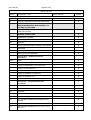
27
PROVISION FOR EARTHING
P
27.1
Accessible metal parts of Class 0I and I appliances, Metal parts are reliable earthed,
permanently and reliably connected to an earthing earthing wire is used for fan
motor and evaporator
terminal
P
Earthing terminals not connected to neutral terminal
P
Class 0, II and III appliance have no provision for
earthing
N
Terminals used for the connection of external
equipotential bonding conductors allow connection
of conductors of 2,5 to 6 mm², and
N
do not provide earthing continuity between different
parts of the appliance
N
Conductors cannot be loosened without the aid of a
tool
N
Clamping means adequately secured against
accidental loosening
N
27.2
27.3
Earth connection "made before" and "separated
after" current-carrying connections
Current-carrying conductors become taut before
earthing conductor, if the cord slips out of the cord
anchorage
TRF No:I60335240C
Result - Remark
Verdict
No such construction.
N
P
TRF originator: AENOR
12011466 001
Page 33 of 54
IEC 60 335-2-40
Clause
Requirement - Test
27.4
No risk of corrosion resulting from contact between
metal of earthing terminal and other metal
P
Adequate resistance to corrosion of coated or
uncoated parts providing earthing continuity, other
than parts of a metal frame or enclosure
P
Parts of steel providing earthing continuity provided
at the essential areas with an electroplated coating,
thickness at least 5 µm
P
Adequate protection against rusting of parts of
coated or uncoated steel, only intended to provide
or transmit contact pressure
P
In case of aluminium alloys precautions taken to
avoid risk of corrosion
27.5
Result - Remark
Verdict
Aluminium alloys not applied.
N
Low resistance of connection between earthing
terminal and earthed metal parts
P
Resistance not exceeding 0,1Ω at the specified low- All of the samples performed the
resistance test
test. The biggest measured
value is 0,07 Ω.
P
27.6
Printed conductors of printed circuit boards not used
to provide earthing continuity in hand-held
appliances or complying the requirements specified
for other appliances (IEC 60335-1/A1:1999)
P
28
SCREWS AND CONNECTIONS
P
28.1
Fixings and electrical connections withstand
mechanical stresses
P
Screws not of soft metal liable to creep, such as
zinc or aluminium
P
Diameter of screws of insulating material min. 3 mm
N
Screws of insulating material not used for any
electrical connection
P
Screws transmitting electrical or providing earthing
continuity contact only screwing into metal (IEC
60335-1/A2:1999)
P
Screws not of insulating material if their replacement
by a metal screw can impair supplementary or
reinforced insulation
P
Type X attachment, screws to be removed for
replacement of supply cord, or for users
maintenance, not of insulating material if their
replacement by a metal screw can impair basic
insulation
N
Screws and nuts of the uses described subjected to Earthing screw, screws of
torque test as specified, applying torque as shown enclosure, and screws of
in table 12 (IEC 60335-1/A2:1999)
terminal: 1,2Nm, 5 times.
P
TRF No:I60335240C
TRF originator: AENOR
12011466 001
Page 34 of 54
IEC 60 335-2-40
Clause
Requirement - Test
28.2
Contact pressure not transmitted through insulating
material liable to shrink or distort, unless shrinkage
or distortion compensated
P
The requirement is not applicable in circuits carrying
current less than 0,5 A (IEC 60335-1/A2: 1999)
P
Space-threaded (sheet metal) screws only used for
the electrical connection if they clamp these parts
directly in contact with each other (IEC 60335-1/A2:
1999)
N
Thread-cutting (self-tapping) screws not used for
electrical connections, unless generating a full form
standard machine screw thread
P
Thread-cutting (self-tapping) screws not used if they
are likely to be operated by the user or installer
unless the thread is formed by a swaging action
N
28.3
Use of thread-cutting and space-threaded screws
for earthing continuity according to specification
28.4
Verdict
At least two self-tapping screws
used
Screws for current-carrying mechanical connection Star washer used
or screws providing earthing continuity secured
against loosening
Rivets for electrical connections and for earthing
continuity subject to torsion secured against
loosening (IEC 60335-1/A2:1999)
29
CREEPAGE DISTANCES, CLEARANCES AND
DISTANCES THROUGH INSULATION
29.1
Creepage distances and clearances not less than
specified in table 13
29.2
Result - Remark
P
P
No rivet for electrical
connection.
N
P
(see appended table)
P
Values increased by 4 mm in case of reinforced
insulation when resonance voltage
N
Creepage distances and clearances for circuits with
voltages greater than 250 V r.m.s. (345 V peak)
comply with table (IEC 60335-2-40:1995)
P
For motor-compressors with working voltages ≤
250 V, 29.1 of IEC 60335-2-34 applies (IEC 603352-40:1995)
N
Creepage distances and clearances for motorcompressors with working voltages > 250 V r.m.s.
and ≤ 600 V r.m.s. not less than stated in Table 101
(IEC 60335-2-40:1995)
P
Distances through insulation not less than 1,0 mm
for supplementary insulation, and 2,0 mm for
reinforced insulation. Interpretation of this
requirement: see Interpretation Sheet I-SH 02,
August, 1994
P
TRF No:I60335240C
TRF originator: AENOR
12011466 001
Page 35 of 54
IEC 60 335-2-40
Clause
Requirement - Test
29.2.1
Supplementary insulation applied in thin sheet form, No such constructions.
other than mica or similar scaly material, consists of
at least two layers, each of the layers withstands the
electric strength test of 16.3 for supplementary
insulation
N
Reinforced insulation applied in thin sheet form,
No such constructions.
other than mica or similar scaly material, consists of
at least three layers, and any two of the layers
together withstand the electric strength test of 16.3
for reinforced insulation
N
Supplementary or reinforced insulation inaccessible
and does not exceed the maximum permissible
temperature values
N
Supplementary or reinforced insulation, after
conditioning as specified, withstands the electric
strength test as specified in 16.3, both at the oven
temperature and room temperature
N
30
RESISTANCE TO HEAT, FIRE AND TRACKING
P
30.1
See Annex H
P
Relevant external parts of non-metallic material
P
Parts supporting live parts and parts providing
supplementary or reinforced insulation sufficiently
resistant to heat
P
29.2.2
Result - Remark
Verdict
Ball-pressure test with a force of 20 N, diameter of
impression not exceeding 2 mm: ............................
(see appended table)
P
External parts: at 75 °C
Enclosure
P
Parts supporting live parts: at 125 °C
Terminal block, PCB
P
Transformer bobbin
Parts providing supplementary or reinforced
insulation: temperature (°C): ....................................
P
30.2
Relevant parts of non-metallic material adequately
resistant to ignition and spread of fire
P
30.2.1
Possible burning test of relevant parts according to
Annex J
N
Glow-wire test of Annex K made at temperature
550 °C
N
Appliances operated while unattended, possible
bad-connection test according to Annex L
N
30.2.3
Glow-wire test of Annex K made at 850 °C
Terminal block, PCB
P
Transformer bobbin
Possible needle-flame test according to Annex M
TRF No:I60335240C
N
TRF originator: AENOR
12011466 001
Page 36 of 54
IEC 60 335-2-40
Clause
Requirement - Test
Result - Remark
Verdict
30.2.4
Parts of non-metallic material within a distance of
50 mm from parts not withstanding the tests of
30.2.2 or 30.2.3, subjected to the needle-flame test
of Annex M
30.3
Relevant insulating material have adequate
resistance to tracking
(see appended table)
P
Tracking test at 175 V according to Annex N
Terminal block, PCB
P
N
Transformer bobbin
Tracking test at 250 V according to Annex N
N
No hazard other than fire, tracking test at 175 V
according to Annex N, and in addition needle-flame
test of surrounding parts according to Annex M
N
Possible needle-flame test of non-metallic material
N
RESISTANCE TO RUSTING
P
Relevant ferrous parts adequately protected against
rusting
P
ANNEX A, NORMATIVE REFERENCES
P
The annex contains a list of standards which are
referred to, and thus become part of, this standard
P
ANNEX C, AGEING TEST ON MOTORS
N
Test carried out when doubt with regard to the
classification of the insulating system of a motor
winding
N
ANNEX E, MEASUREMENT OF CREEPAGE
DISTANCES AND CLEARANCES
P
Methods of measuring creepage distances and
clearances, specified in 29.1, indicated in 10
different cases
P
ANNEX G, CIRCUIT FOR MEASURING
LEAKAGE CURRENTS
P
A suitable circuit for measuring leakage currents is
shown
P
H
ANNEX H, SELECTION AND SEQUENCE OF
THE TESTS OF CLAUSE 30
P
J
ANNEX J, BURNING TEST
N
The burning test is made in accordance with
IEC 707, and method FH is used
N
Category FH3 applies, the maximum burning rate
being 40 mm/min
N
ANNEX K, GLOW-WIRE TEST
P
31
A
C
E
G
K
TRF No:I60335240C
TRF originator: AENOR
12011466 001
Page 37 of 54
IEC 60 335-2-40
Clause
Requirement - Test
Result - Remark
Verdict
The glow-wire test is made in accordance with
IEC 695-2-1 (clause numbers between parentheses
refer to IEC 695-2-1)
P
(4)
Description of test apparatus: the last paragraph
before the note is replaced
P
(5)
Severities: the duration of application of the tip of
the glow-wire to the specimen being (30 ± 1) s
P
(10)
Observations and measurements: item c) does not
apply
P
L
ANNEX L, BAD-CONNECTION TEST WITH
HEATERS
N
The bad-connection test with heaters is made in
accordance with IEC 695-2-3 (clause numbers
between parentheses refer to IEC 695-2-3)
N
(3)
General description of the test: additions concerning
crimped connections
N
(4)
Description of test apparatus: replacements of some
of the test specifications and the first paragraph of
the note
N
(6)
Severities: the duration of application of the test
power being (30 ± 1) min
N
(8)
Test procedure: subclause 8.6 replaced
N
(11)
Information to be given in the relevant specification:
item h), the first dashed paragraph, does not apply
N
M
ANNEX M, NEEDLE-FLAME TEST
N
The needle-flame test is made in accordance with
IEC 695-2-2 (clause numbers between parentheses
refer to IEC 695-2-2)
N
(4)
Description of the apparatus: the sixth paragraph is
replaced
N
(5)
Severities: the duration of application of the test
flame is (30 ± 1) s
N
(8)
Test procedure: some changes in the test
specifications
N
(10)
Evaluation of the test results: addition in the test
specification
N
N
ANNEX N, PROOF TRACKING TEST
P
The proof tracking test is made in accordance with
IEC 112 (clause numbers between parentheses
refer to IEC 112)
P
Test specimen: the last sentence of the first
paragraph does not apply
P
(3)
TRF No:I60335240C
TRF originator: AENOR
12011466 001
Page 38 of 54
IEC 60 335-2-40
Clause
Requirement - Test
(5)
Test apparatus: some changes in the subclauses
P
(6)
Procedure: adjustments of the test specifications
P
P
ANNEX P, SEVERITY OF DUTY CONDITIONS OF
INSULATING MATERIAL WITH RESPECT TO
THE RISK OF TRACKING
P
Recognition of different duty conditions with respect
to the risk of tracking
P
ANNEX Q, CAPACITORS
N
Section one – General
N
1.5
Terminology
N
1.5.3
Applicable
N
Class X capacitors tested according to subclass X2
N
1.5.4
Applicable
N
1.6
Marking
N
Items a) and b) are applicable
N
Section three – Quality assessment
procedures
N
Tests
N
Table II is applicable as follows
N
- Group 0: subclauses 4.1.,4.2.1 and 4.2.5
N
- Group 1 A: subclause 4.1.1
N
- Group 2: subclause 4.12
N
- Group 3: subclause 4.13 and 4.14
N
- Group 6: subclause 4.17
N
- Group 7: subclause 4.18
N
Section four – Test and measurement
procedures
N
4.1
Visual examination and check the dimensions
N
4.2
Electrical tests
N
4.2.1
Applicable
N
4.2.5
Applicable
N
4.2.5.2
Only table IX is applicable
N
4.12
Only insulation resistance and voltage proof are
checked
N
4.13
Applicable
N
4.14
Applicable with subclauses 4.14.1, 4.14.3, 4.14.4
and 4.14.7
N
Q
3.4.3.2
TRF No:I60335240C
Result - Remark
Verdict
TRF originator: AENOR
12011466 001
Page 39 of 54
IEC 60 335-2-40
Clause
Requirement - Test
4.14.7
Only insulation resistance and voltage proof are
checked together with a visual examination to
ensure that there is not visible damage
N
4.17
Applicable
N
4.18
Applicable
N
R
ANNEX R, SAFETY ISOLATING TRANSFORMER
N
Safety isolation transformer tested with the
appliance comply with this standard and the
following requirements:
N
R.7
Marking and instruction
N
R.7.1
Transformer for specific use shall be marked with:
N
- name, trade-mark or identification mark of the
manufacturer or responsible vendor
N
- model or type reference
N
Overload protection of transformers and
associated circuits
N
Fail-safe transformer shall comply with 15.5 of IEC
61558-1
N
Construction
N
Subclauses 19.1. and 19.1.2. of IEC 61558-2-6 are
applicable
N
Creepage distances, clearances and
distances through insulation
N
The distances specified in items 2 a, 2 b, and 3 in
table 13 of IEC 61558-1 apply
N
ANNEX S – SWITCHES
P
Switches tested with the appliance comply with this
standard and with the following clauses of IEC
61058-1:
P
Test of EN 61058-1 carry out under the conditions
occurring in the appliance
P
Before the test, switches are operated 20 times
without load
P
Marking and documentation
P
Switches are not required to be marked, except that
incorporated switches shall be marked
P
Mechanism
N
This clause is applicable
N
Insulation resistance and dielectric strength
N
15.1 and 15.2 not applicable
N
R.17
R.22
R.29
S
8
13
15
TRF No:I60335240C
Result - Remark
Verdict
TRF originator: AENOR
12011466 001
Page 40 of 54
IEC 60 335-2-40
Clause
Requirement - Test
Result - Remark
Verdict
15.3 is applicable for disconnection and microdisconnection
N
Endurance
P
Compliance is checked on three separate
appliances or switches
P
At the end of the tests, the temperature rise of
terminals shall not have increased by more than 30
K above the temperature rise measured in clause
11
P
Clearances, creepage and distances through
insulation
P
Only applicable for live parts of different potential
P
DIFFERENCES EXISTING IN SOME COUNTRIES
(IEC 60335-1)
N
2.5.2
U.S.A.: safety extra-low voltage not exceeding 30 V
(42,2 V peak)
N
2.8.5
AUSTRALIA, NEW ZEALAND: disconnection of
supply not considered as a manual operation
N
3
AUSTRALIA: the d.c. component in appliance
neutral is limited
N
4.7
CHINA, JAPAN AND U.S.A.: ambient testing
temperature is 25 °C ± 10 °C
N
4.14
U.S.A.: accessible metal parts not liable to become
energised do not need earthing; accessible nonmetallic parts provide only basic insulation
N
6.1
AUSTRALIA, AUSTRIA, CZECH REPUBLIC,
FINLAND, FRANCE, GERMANY, HUNGARY,
IRELAND, ITALY, NETHERLANDS, NEW
ZEALAND, POLAND, SINGAPORE, SWEDEN,
UNITED KINGDOM AND YUGOSLAVIA: Class 0
and Class I appliances not allowed
N
6.2
U.S.A.: methods for protection against harmful
ingress of water different from IEC 529
N
7.1
U.S.A.: IP number not required to be marked
N
7.6
U.S.A.: some of these symbols not used
N
7.8
U.S.A.: additional methods for identifying earthing
terminals for neutral conductors
N
7.12.2
AUSTRALIA, JAPAN, NEW ZEALAND AND U.S.A.:
the 3 mm contact separation not applicable
N
7.14
U.S.A.: different tests used
N
8.1.1
U.S.A.: test not necessarily repeated with the 20 N
force
N
17
18
TRF No:I60335240C
TRF originator: AENOR
12011466 001
Page 41 of 54
IEC 60 335-2-40
Clause
Requirement - Test
Result - Remark
Verdict
U.S.A.: protection against contact with live parts of
the lamp cap not required
N
8.1.2
U.S.A.: test pin and test probe not used
N
8.1.3
U.S.A.: test pin and test probe not used
N
8.1.5
U.S.A.: built-in and fixed appliances and appliances
in separate units not to be protected by at least
basic insulation before installation
N
9
U.S.A.: motors required starting without blowing a
quick-acting fuse
N
10.1
U.S.A.: positive limits of 5% for heating appliances
and 10% for motor-operated appliances required;
no negative deviations
N
10.2
U.S.A.: positive limits of 5% for heating appliances
and 10% for motor-operated appliances required;
no negative deviations
N
11.4
U.S.A.: heating appliances and heater circuits
operated at rated power input or rated voltage (the
more severe); the rest at rated voltage
N
11.5
U.S.A.: heating appliances and heater circuits
operated at rated power input or rated voltage (the
more severe); the rest at rated voltage
N
11.6
U.S.A.: heating appliances and heater circuits
operated at rated power input or rated voltage (the
more severe); the rest at rated voltage
N
11.8
U.S.A.: temperature rise limits different for certain
materials (Table 3)
N
13.2
U.S.A.: test circuit and some leakage current limits
different
N
13.3
U.S.A.: certain test voltages different
N
U.S.A.: a 500 VA test transformer used
N
15.1.1
U.S.A.: IP system not used; tests different
N
15.1.2
U.S.A.: IP system not used; tests different
N
15.3
U.S.A.: relative humidity of (88 ± 2) % and
temperature of 32 °C ± 2 °C during test
N
16.2
U.S.A.: test at nominal supply voltage; leakage
current values different
N
16.3
U.S.A.: some test voltages and methods different
N
19.1
U.S.A.: circuit protection device permitted
N
19.2
U.S.A.: tests normally at nominal supply voltage or
rated power input
N
19.4
TRF No:I60335240C
TRF originator: AENOR
12011466 001
Page 42 of 54
IEC 60 335-2-40
Clause
Requirement - Test
19.13
U.S.A.: temperature rise limits of Table 7 not
applicable
N
20.1
U.S.A.: stability test at 15 degrees not conducted;
test in overturned position judged under abnormal
test criteria
N
21
U.S.A.: impact force applied with a falling steel ball
N
22.1
U.S.A.: IP system not used; tests not the same as in
IEC 529
N
22.2
FRANCE AND NORWAY: single-phase Class I
appliances with heating elements not complying
because of the supply system
N
NORWAY: double-pole switches or protective
devices required
N
U.S.A.: set of terminals for connection of a flexible
cord generally not permitted
N
U.S.A.: disconnection of the neutral not necessary
for all stationary appliances
N
IRELAND AND UNITED KINGDOM.: plug not
required in supply cord
N
22.6
U.S.A.: test not conducted
N
22.11
U.S.A.: different criteria for snap-on constructions
required
N
22.12
U.S.A.: positive forms of securement required
N
22.14
U.S.A.: sharp edges testing device used to evaluate
sharp edges
N
22.35
U.S.A.: double or reinforced insulation not required
on metal parts
N
22.36
U.S.A.: double or reinforced insulation not required
on metal parts
N
23.5
U.S.A.: different requirements for insulated internal
wiring
N
23.7
NEW ZEALAND AND U.S.A.: green wiring used
instead of green/yellow wiring
N
U.S.A.: requirement applies to accessible wiring
during supply connections
N
U.S.A.: different number of cycles required; note 2
not applicable
N
U.S.A.: note not applicable
N
U.S.A.: requirement for 3 mm contact separation not
applicable
N
24.1.3
24.3
TRF No:I60335240C
Result - Remark
Verdict
TRF originator: AENOR
12011466 001
Page 43 of 54
IEC 60 335-2-40
Clause
Requirement - Test
25.1
IRELAND AND UNITED KINGDOM: plug not
required in supply cord
N
25.3
DENMARK, FINLAND, NETHERLANDS, NORWAY
AND SWEDEN: set of supply leads not permitted
N
U.S.A.: set of terminals for connection of a flexible
cord generally not permitted
N
AUSTRALIA, NEW ZEALAND AND U.S.A.: different
conductor cross-sectional areas
N
AUSTRALIA, NEW ZEALAND: 0,5 mm² supply
cords not allowed for Class I appliances
N
25.10
U.S.A.: green insulation also permitted
N
25.14.2
U.S.A.: only one separate insulation required
N
25.16
AUSTRALIA: fully removable cord anchorages
allowed
N
U.S.A.: pull of 35 lbs applied; torque test not used
N
26.2
U.S.A.: cross-sectional areas according to AWG
N
26.4
U.S.A.: tests only apply to terminals for connection
to fixed wiring
N
26.5
U.S.A.: tests only apply to terminals for connection
to fixed wiring
N
27.2
U.S.A.: different requirements for screwless
terminals (IEC 685-2-1 not used)
N
28.1
U.S.A.: this type of tests not required
N
29.1
U.S.A.: different creepage distances and clearances
may be applicable
N
30.1
U.S.A.: minimum value for ball-pressure test for
parts retaining live parts is 95 °C or 40 K higher than
Cl. 11 temperature rise; for enclosures, 75 °C is the
minimum value or mould-stress test conducted at
10 K above Cl. 11 temperatures
N
30.2.1
U.S.A.: ignition test not used to assure a slow
burning rate
N
30.2.4
AUSTRALIA: printed circuit boards at mains voltage
shall be FV-0 or FV-1 or meet needle-flame test
N
B.7.12
SWEDEN AND SWITZERLAND: appliances with
non-replaceable batteries with a content of mercury
or cadmium exceeding 0,025% by weight
adequately marked
N
B.21.101
U.S.A.: different requirement
N
F.1.1
U.S.A.: annex applies to motors with a working
voltage ≤ 30 V
N
25.8
TRF No:I60335240C
Result - Remark
Verdict
TRF originator: AENOR
12011466 001
Page 44 of 54
IEC 60 335-2-40
Clause
Requirement - Test
Result - Remark
Verdict
DIFFERENCES EXISTING IN SOME COUNTRIES
(IEC 60335-2-40)
N
3
AUSTRALIA: the D.C. component in appliance
neutral is limited
N
6.1
JAPAN: Class 0I appliances allowed
N
11.8
SWEDEN: temperature of the wooden walls in test
casing limited to 85 °C
N
10
TABLE: input power and current
P
Operation mode:........................... Cooling and heating
P
Test voltage (V): .......................... 230
—
Model
Rated
cooling (W)
Rated
heating (W)
Measured
cooling (W)
Measured
heating (W)
Deviation
cooling (%)
Deviation
heating (%)
WNG25 DCI
32
32
30
33
-6,3%
3,1%
WNG35 DCI
40
40
43
41
7,5%
2,5%
WNG50 DCI
56
56
58
57
3,5%
1,8%
WNG60 DCI
59
59
62
60
5,1%
1,7%
11.8
TABLE: TEMPERATURE RISE MEASUREMENTS
P
WNG35 DCI
Operation mode..................................... Cooling and heating
P
t1 (°C) .................................................... 21
—
t2 (°C) .................................................... See remark
—
Test voltage (V) .................................... 254V
—
Measured temperature (°C)
Limit temperature (°C)
Fan motor enclosure
1*)
41,2
150
Fan motor enclosure
2*)
52,6
150
Fan motor capacitor enclosure
50,4
T70
Ambient of fan motor replay (5mm)
47,5
T55
Ambient of compressor replay (5mm)
42,4
T55
Transformer winding enclosure
48,6
110
Terminal block
35,7
Material test
Main PCB
34,6
Material test
Temperature T of part:
Winding temperature rise measurements:
P
K = 234,5 for copper windings ............................... :
Copper winding
-
K = 225 for aluminum windings .............................. :
N/A
-
Insulation class ....................................................... :
See below
-
YYW20-4-488
TRF No:I60335240C
165/223
204/275
80/79
115
E
TRF originator: AENOR
12011466 001
Page 45 of 54
IEC 60 335-2-40
Clause
Requirement - Test
RPG13P
Result - Remark
270/460
337/569
88/86
Verdict
115
E
Remark 1: The heating test was performed at the high speed and low speed of fan motor, the highest value was
listed.
Remark 2: The test was performed on heating and cooling mode, the highest value was listed.
Remark 3: the WNG25DCI is similar with model WNG35DCI, so heating test was performed on model
WNG35DCI to represent model WNG25DCI.
Remark 4: 1*) for motor: YYW20-4-488;
2*)
for motor: RPG13P
11.8
TABLE: TEMPERATURE RISE MEASUREMENTS
P
WNG60 DCI
Operation mode..................................... Cooling and heating
P
t1 (°C) .................................................... 21
—
t2 (°C) .................................................... See remark
—
Test voltage (V) .................................... 254V
—
Temperature T of part:
Measured temperature (°C)
Limit temperature (°C)
Enclosure of fan motor
79,0
150
Fan motor capacitor enclosure
39,5
T70
Ambient of fan motor replay (5mm)
43,9
T55
Ambient of compressor replay (5mm)
35,7
T55
Transformer winding enclosure
48,6
110
Terminal block
35,7
Material test
Main PCB
33,1
Material test
Winding temperature rise measurements:
P
K = 234,5 for copper windings ............................... :
Copper winding
-
K = 225 for aluminum windings .............................. :
N/A
-
Insulation class ....................................................... :
See below
-
RPG30Z
165/223
202/273
78/78
115
E
Remark 1: The heating test was performed at the high speed and low speed of fan motor, the highest value was
listed.
Remark 2: The test was performed on heating and cooling mode, the highest value was listed.
Remark 3: Model WNG50DCI is similar with model WNG60DCI, so the heating test was performed on model
WNG60DCI to represent model WNG50DCI.
13.2
TABLE: leakage current measurements at operating temperature
P
Heating appliances: at 1.15 times rated input (W) : N/A
—
Motor-operated and combined appliances: at
254V
1.06 times rated voltage (V) ................................... :
—
Leakage current I between:
I (mA)
Required I (mA)
L/N-enclosure
0,063
0,25
TRF No:I60335240C
TRF originator: AENOR
12011466 001
Page 46 of 54
IEC 60 335-2-40
Clause
Requirement - Test
Result - Remark
L/N-earthing part
0,88
Verdict
3,5
Remark: Test performed on all test samples and the highest value was listed.
13.3
TABLE: electric strength measurements at operating temperature
Test voltage applied between:
P
Test voltage (V)
Breakdown
L/N – GND
1000
No
L/N – enclosure of indoor unit (aluminium foil)
3750
No
Remark: Test performed on all test samples
16.2
TABLE: LEAKAGE CURRENT MEASUREMENTS
P
At 1,06 times rated voltage (V) .............................: 254V
-
Measured between:
Measured (mA)
Limit (mA)
L/N –GND
0,54
3,5
L/N – non-conductive enclosure
0,023
0,25
Remark: Test performed on all test samples and the highest value was listed.
16.3
TABLE: electric strength measurements
Test voltage applied between:
P
Test voltage (V)
Breakdown
L/N – GND
1250
No
L/N - enclosure of indoor unit (aluminium foil)
3750
No
Point where motor winding connected with capacitor-protective
earth
1900
No
Point where compressor winding connected with capacitorprotective earth
1900
No
Remark: Test performed on all models.
17.1
TABLE: OVERLOAD PROTECTION
P
at 1,06 - 0,94 times rated voltage (V)....................: 254V
-
Test model:
-
Short-circuit of:
SC secondary winding (pri/sec):
PE41230A006Ga
Measured
temperature (°C)
Limit temperature
(°C)
Result
120/121
225
P
Remark: 5 minutes later, overload protector of the transformer operated.
TRF No:I60335240C
TRF originator: AENOR
12011466 001
Page 47 of 54
IEC 60 335-2-40
Clause
Requirement - Test
Result - Remark
Verdict
17.1
TABLE: OVERLOAD PROTECTION
P
at 1,06 - 0,94 times rated voltage (V)....................: 254V
-
Test model:
-
DB36-E135-1601
Short-circuit of:
Measured
temperature (°C)
Limit temperature
(°C)
Result
126/129
225
P
SC secondary winding (pri/sec):
Remark: 2 minutes later, overload protector of the transformer operated.
17.1
TABLE: OVERLOAD PROTECTION
P
at 1,06 - 0,94 times rated voltage (V)....................: 254V
-
Test model:
-
OH35289ET
Short-circuit of:
Measured
temperature (°C)
Limit temperature
(°C)
Result
125/126
225
P
SC secondary winding (pri/sec):
Remark: 3 minutes later, overload protector of the transformer operated.
17.1
TABLE: OVERLOAD PROTECTION
P
at 1,06 - 0,94 times rated voltage (V)....................: 254V
-
Test model:
-
DB-EI35-2982A
Short-circuit of:
Measured
temperature (°C)
Limit temperature
(°C)
Result
129/132
225
P
19.2
TABLE: lock motor test, temperature rise measurements
P
Test procedure
Supplied with rated voltage (230V)
-
Duration
15 days, after 3 days HV test performed
-
Ambient
temperature [°C]
21
-
Measured samples
Insulation
SC secondary winding (pri/sec):
Remark: 3 minutes later, overload protector of the transformer operated.
Class
Enclosure
temperature
[°C]
Winding temperature [°C]
HV test
performed
with 1250V
Leakage current
[mA]
RPG13P
E
90,8
97,5
(Protector operated within 1 h)
P
0,009
YYW20-4-488
E
91,1
99,1
(Protector operated within 1 h)
P
0,009
RPG30Z
E
93,2
98,7
(Protector operated within 1 h)
P
0,009
TRF No:I60335240C
TRF originator: AENOR
12011466 001
Page 48 of 54
IEC 60 335-2-40
Clause
Requirement - Test
Result - Remark
Verdict
19.11.2
TABLE: fault condition tests:
P
Ambient temperature (°C): .................................... Cooling: 32/23(IU), 43/26(OU)
-
Heating: 27/-(IU), 24/18(OU)
Test voltage (V): ................................................... 230
Fault condition
-
Phenomenon
Hazard
1. SC fan motor capacitor
(cooling)
The fan motor stopped. A few minutes later, appliance stopped.
No
2. SC fan motor capacitor
(heating)
The appliance stopped.
No
3. OC fan motor capacitor
(cooling)
The indoor fan motor stopped. A few minutes later, appliance
stopped.
No
4 OC fan motor capacitor
(heating)
The fan operated slowly. The appliance worked normally with
input increased.
No
5. Short secondary circuit
of SPS transformer
The appliance did not work, temperature rise of the SPS
transformer enclosure was 12K.
No
Remark: the “SC” means short-circuited, “OC” means open-circuited
24.1
TABLE: COMPONENTS
Object/part No.
Manufacturer/
trademark
P
Type/model
Technical data
Standard
Mark(s) of
conformity
Remark 1: For thermal cut-outs, thermal links of compressors, fan motors and transformers which have been
approved according to relevant EN/IEC standards, the manufacturer, types and characters not
listed in the CDF but should be in this scope authorized by original certification bodies.
Remark 2: “*” means the components are accessories which can be selected by the client.
Built-in components with windings: (motors, transformers, magnetic coils etc.)
For model WNG25 DCI, WNG35 DCI
Main: 274±8%Ω
Fan motor (IU)
Welling
RPG13P
Alux: 466±8%Ω
(at 25℃) ,class E
Main: 262±8%Ω
Alternate
Wolong
YYW20-4-488
Alux: 572±8%Ω
(at 25℃) ,class E
Protector in fan
motor
Jiangsu
Changheng
BW series
Alternate
Jiangsu
changheng
BRLD
Alternate
Desheng
BR-B3D
Louver fan
motor
Leili Electrical
PM 24
TRF No:I60335240C
250V 16A
Operated temp.: 100±5°C
250V 16A
Operated temp.: 100±5°C
250V 16A
Operated temp.: 100±5°C
300Ω 12VDC
IEC 60335-2- Tested with
40
appliance
IEC 60335-2- Tested with
40
appliance
IEC 60730
VDE
IEC 60730
VDE
IEC 60730
VDE
IEC 60335-2- Tested with
40
appliance
TRF originator: AENOR
12011466 001
Page 49 of 54
IEC 60 335-2-40
Clause
Requirement - Test
Result - Remark
Verdict
Alternate
HuaYang
24BYJ48
300Ω 12VDC
IEC 60335-2- Tested with
40
appliance
Alternate
HuaXia
24BYJ48
200Ω 12VDC
IEC 60335-2- Tested with
40
appliance
Transformer
Helms-Man
Industrial
Pri.: 230VAC 50Hz
PE41230A006G sec.:12,5VAC 500mA
a
Class B
Thermal link in
transformer
Joint Force Metal
M30
Research & Co.
AC250V 2A
Electra HK
DCI- WNG
Technologies Ltd
Shang dong
DJQ-04
xue sheng
AC220~240V
50/60 Hz,
IEC 60335-2- Tested with
40
appliance
DC12V
IEC 60335-2- Tested with
40
appliance
Controller
ESF for WNG *
Operated temp.: 125°C
IEC 60335-2- Tested with
40
appliance
IEC 60691
VDE
IEC 60335-2- Tested with
40
appliance
IEC 60335-2- Tested with
40
appliance
Ionzier *
EHK
ION G1
DC12V
Alternate
Shangdong
xuesheng
ION G1
DC12V
Ionzier power
box *
EHK
ION POWER
BOX
Input voltage: DC12V
Alternate
Shangdong
xuesheng
ION POWER
BOX
Transformer for
ESF and ION *
New Era
DB36-E1351601
Input voltage: DC12V
Output voltage :DC6-12V
Pri.: 230VAC 50Hz
sec.:12,5VAC 500mA
Class B
Alternate
Dongguan
Oriental Hero
Electrical
OH35289ET
Pri.: 230V±5%
sec.:19VAC 160mA
Class B
IEC 60335-2- Tested with
40
appliance
Alternate
Jing quan hua
DB-EI35-2982A
Pri.: 230VAC 50Hz
sec.:14VAC 250mA
Class B
IEC 60335-2- Tested with
40
appliance
Protector for
ESF and ION
Transformer *
Auto Electronics
Ltd;
A4
250V 2A
IEC 60335-2VDE
40
IEC 60335-2- Tested with
appliance
Output voltage :DC6-12V 40
Operated temp.: 130°C
IEC 60335-2- Tested with
40
appliance
IEC 60335-2- Tested with
40
appliance
Built-in components : (switches, thermostats, heater, plugs, wires, capacitors, sockets, RFI-filters etc.)
Plug
Optional
Optional
250V 13~16A
IEC 60083
TUV or any
CENELEC
Power cord
Optional
H05V-F or
H07VV-F
1,5 mm2
IEC 60227
TUV or any
CENELEC
Terminal
Jiangsu
Changheng
JX-W-6
380V 2,5mm2
IEC 60335-1
Tested with
appliance
Alternate
Huang Zhong
ET-16-6
450 VAC,4mm2
IEC 60335-1
Tested with
appliance
Thermal link in
transformer
Joint Force Metal
M30
Research & Co.
250V, 2A
Operated temp.: 125°C
IEC 60691
VDE
TRF No:I60335240C
TRF originator: AENOR
12011466 001
Page 50 of 54
IEC 60 335-2-40
Clause
Requirement - Test
PCB (material)
Kinwong
Alternate
GLORYFAITH
Alternate
TAT CHUN
Result - Remark
1,6mm FR4
double sided
1,6mm FR4
double sided
1,6mm FR4
double sided
Verdict
94V0
--
UL
94V0
--
UL
94V0
--
UL
3,15A/250VAC
IEC 60127
TUV or any
CENELEC
Safety components in controller (IU)
Fuse in
controller
Optional
Varistor
Thinking
TVR 14561
AC350V
CECC42000
VDE
Alternate
Harris
V320LA20A
AC350V
--
UL
Alternate
Nippon(Marcon)
TNR14V561K
AC350V
CECC42000
VDE
Relay for Indoor
Matsushita
fan motor
ALD112
3A, 250VAC
T55 or above
IEC 60730
VDE
Alternate
Hong Fa
JZC-43F/012HS
3A, 250VAC
T55 or above
IEC 60730
VDE
Alternate
Omron
G5NB-1A12VDC
3A, 250VAC
T55 or above
IEC 60730
VDE
Relay for
outdoor fan
motor
Matsushita
JQ1AP-12V
10A 250V
Temp 55°C or above
IEC 60255
VDE
Alternate
HongFa
JZC-33F-012
10A 250V
Temp 55°C or above
IEC 60255
VDE
Alternate
OMRON
G5Q-1A-12VDC
10A 250V
Temp 55°C or above
IEC 60255
VDE
X2 filter
capacitor
Tenta
MEX series
0,1µF/275VAC T mark:
85°C or above
IEC 6038414
VDE
Standard
Mark(s) of
conformity
“F” type
For model WNG50 DCI, WNG60 DCI
Object/part Manufacturer/
Type/model
No.
trademark
Technical data
Remark 1: For thermal cut-outs, thermal links of compressors, fan motors and transformers which have been
approved according to relevant EN/IEC standards, the manufacturer, types and characters not
listed in the CDF but should be in this scope authorized by original certification bodies.
Built-in components with windings: (motors, transformers, magnetic coils etc.)
220-240V Class E
Fan motor
Welling
RPG30Z
Main: 165±8%Ω
BW series
250V 16A
Operated temp.:
Aux.: 220±8%Ω
Protector in fan Jiangsu
motor
Changheng
TRF No:I60335240C
100±5°C
IEC 60335-2- Tested with
40
appliance
IEC 60730
VDE
TRF originator: AENOR
12011466 001
Page 51 of 54
IEC 60 335-2-40
Clause
Requirement - Test
Alternate
Alternate
Jiangsu
Changheng
Desheng
Result - Remark
BRL2D
250V 16A
Operated temp.:
Verdict
IEC 60730
VDE
IEC 60730
VDE
100±5°C
BR-B3D
250V 16A
Operated temp.:
100±5°C
Louver motor
Huaxia
24BYJ48
Main: 300Ω
DC12V
IEC 60335-2- Tested with
40
appliance
Alternate
Leili
24BYJ48
Main: 300Ω
DC12V
IEC 60335-2- Tested with
40
appliance
Alternate
Huaxia
24BYJ48
Main: 300Ω
DC12V
IEC 60335-2- Tested with
40
appliance
--
Input voltage:
198~264 VAC
Input current ~ 0,1A
Output voltage:
+12VDC 0,3A max
+5VDC 0,3A max
IEC 60335-2- Tested with
40
appliance
SPS
transformer in
controller
EHK
Transformer for
New Era
ESF and ION *
Pri.: 230VAC 50Hz
DB36-E135-1601 sec.:12,5VAC 500mA
Class B
IEC 60335-2- Tested with
40
appliance
Alternate
Dongguan
Oriental Hero
Electrical
OH35289ET
Pri.:230V±5%
sec.:19VAC 160mA
Class B
IEC 60335-2- Tested with
40
appliance
Alternate
Jing quan hua
DB-EI35-2982A
Pri.: 230VAC 50Hz
sec.:14VAC 250mA
Class B
IEC 60335-2- Tested with
40
appliance
Protector for
ESF and ION
Transformer *
Auto electronics
Ltd.
A4
Controller
Electra HK
Technologies Ltd
DCI-WNG18
ESF for WNG *
Shang dong
xue sheng
DJQ-13
IONIZER *
EHK
ION G1
DC12V
Alternate
Shang dong xue
sheng
ION G1
DC12V
Ionzier power
box *
EHK
ION POWER
BOX
Input voltage: DC12V
Output voltage :DC612V
IEC 60335-2- Tested with
40
appliance
Alternate
Shangdong
xuesheng
ION POWER
BOX
Input voltage: DC12V
Output voltage :DC612V
IEC 60335-2- Tested with
40
appliance
250V 2A
IEC 60335-2VDE
Operated temp.: 130°C 40
-DC12V
IEC 60335-2- Tested with
40
appliance
IEC 60335-2- Tested with
40
appliance
IEC 60335-2- Tested with
40
appliance
IEC 60335-2- Tested with
40
appliance
Built-in components : (switches, thermostats, heater, plugs, wires, capacitors, sockets, RFI-filters etc.)
TRF No:I60335240C
TRF originator: AENOR
12011466 001
Page 52 of 54
IEC 60 335-2-40
Clause
Requirement - Test
Result - Remark
Verdict
IEC 60083
TUV or any
CENELEC
IEC 60227
TUV or any
CENELEC
450VAC 4,0mm2
IEC 60335-1
Tested with
appliance
ET-16-6
450VAC 4,0mm2
IEC 60335-1
Tested with
appliance
Kinwong
1,6mm FR4
94V0
--
UL
Alternate
GLORYFAITH
1,6mm FR4
94V0
--
UL
Alternate
TAT CHUN
1,6mm FR4
94V0
--
UL
Plug
Optional
Optional
250V 16~20A
Power cord
Optional
H05VV or H07VV 2,5mm2
Terminal block
Jiangsu
Changheng
JX-W-6
Alternate
Huang Zhong
PCB (material)
Safety components in controller (IU)
Fuse in
controller
Optional
T type
T 3,15A/250VAC
IEC 60127
TUV or any
CENELEC
Varistor
Thingking
TVR 14561
AC350V
CECC42000
VDE
Alternate
Harris
V320LA20A
AC350V
--
UL
Alternate
Nippon(Marcon)
TNR14V561K
AC350V
CECC42000
VDE
Relay for
Indoor fan
motor
Matsushita
ALD112
3A, 250VAC
T55 or above
IEC 60255
VDE
Alternate
Hong Fa
JZC-43F/012HS
3A, 250VAC
T55 or above
IEC 60255
VDE
Alternate
OMRON
G5NB-1A-12VDC
3A, 250VAC
T55 or above
IEC 60255
VDE
Relay for
outdoor fan
motor
Matsushita
JQ1aP-12V
10A 250V
T55 or above
IEC 60255
VDE
Alternate
HongFa
JZC-33F-012
10A 250V
T55 or above
IEC 60255
VDE
Alternate
OMRON
G5Q-1A-12VDC
10A 250V
T55 or above
IEC 60255
VDE
Filter capacitor
X2
(C34,C56)
Iskra
KNB1530 series
0,1µF/275VAC
Temp 85°C or above
IEC 6038414
VDE
Alternate
Tenta
MEX series
0,1µF/275VAC
Temp 85°C or above
IEC 6038414
VDE
Alternate
Iskra
KNB1560 series
0,1µF/275VAC
Temp 85°C or above
IEC 6038414
VDE
PHE840M series
0,1µF/275VAC
Temp 85°C or above
IEC 6038414
VDE
Alternate
Evox Rifa
TRF No:I60335240C
TRF originator: AENOR
12011466 001
Page 53 of 54
IEC 60 335-2-40
Clause
Requirement - Test
Result - Remark
Verdict
RE series
0,1µF/275VAC
Temp 85°C or above
IEC 6038414
VDE
Filter capacitor
Y2
YA-NAY CO
(C39,C46,C48,
C49,C51)
JY series
2,2nF/250VAC
Temp 85°C or above
IEC 6038414
VDE
Alternate
Murata
KH series
2,2nF/250VAC
Temp 85°C or above
IEC 6038414
VDE
Alternate
TDK
CS series
2,2nF/250VAC
Temp 85°C or above
IEC 6038414
VDE
Filter capacitor
Y2
(C60)
JYA-NAY CO.
JY series
1nF/250VAC
Temp 85°C or above
IEC 6038414
VDE
Alternate
Murata
KH series
1nF/250VAC
Temp 85°C or above
IEC 6038414
VDE
Alternate
TDK
CS series
1nF/250VAC
Temp 85°C or above
IEC 6038414
VDE
Alternate
Iskra
KNB2520
1nF/250VAC
Temp 85°C or above
IEC 6038414
VDE
Alternate
Okaya
29.1
TABLE: MINIMUM CREEPAGE DISTANCES AND CLEARANCES
creepage (cr) and clearance (cl)
Class III
Other appliances, working voltage:
distance (mm):
appliances
< 130 V
130-250 V
P
Remark
250-440 V
cr
cl
cr
cl
cr
cl
cr
cl
1,0
1,0
1,0
1,0
3,1
3,1
2,0
2,0
P
-if not protected against deposition of
dirt
2,0
1,5
2,0
1,5
4,0
4,0
4,0
3,0
P
-if lacquered or enameled windings
1,0
1,0
1,5
1,5
4,0
4,0
3,0
3,0
P
1,0
1,0
1,0
1,0
N
Between live parts of different potential
-if protected against deposition of dirt
- for positive temperature coefficient
(PTC) resistors including their
connecting wires, if protected against
deposition of moisture or dirt
Cl and Cr measured between:
1. L and N on PCB;
2. L and N on terminal block;
3. Input of transformer;
4. Winding of fan motor.
The shortest value is considered.
Between live parts and other metal parts over basic insulation:
- if protected against deposition of
dirt:
TRF No:I60335240C
N
TRF originator: AENOR
12011466 001
Page 54 of 54
IEC 60 335-2-40
Clause
Requirement - Test
Result - Remark
Verdict
- if of ceramic material, pure mica
and similar material
1,0
1,0
1,0
1,0
2,5
2,5
N
- if of other material
1,5
1,0
1,5
1,0
3,0
2,5
N
- if not protected against deposition
of dirt
2,0
1,5
2,0
1,5
4,0
4,0
P
- if the live parts are lacquered or
enamelled windings
1,0
1,0
1,5
1,5
4,0
4,0
P
1,0
1,0
1,0
1,0
N
- at the end of tubular sheathed-type
heating elements
Cl and Cr measured between:
1. Live part on PCB and earting metal part;
2. Live part on terminal and earthing metal part;
3. Winding of transformer/fan motor and enclosure/body;
4. Live part on PCB and lower voltage parts;
The shortest value is considered.
Between live parts and other metal parts over reinforced insulation
- if the live parts are lacquered or
enamelled windings
6,0
6,0
6,0
6,0
N
- for other live parts
8,0
8,0
10,0
10,0
P
Cl and Cr measured between:
1. Test finger and internal live part through the gap of enclosure.
The shortest value is considered.
between metal parts separated by
supplementary insulation
between live parts in recesses in the
mounting face of the appliance and
the surface to which it is fixed
30. 1
4,0
4,0
4,0
4,0
N
2,0
2,0
6,0
6,0
6,0
6,0
N
TABLE: material test
Part name/No.
P
Ball-pressure test
Glow-wire test
Tracking test (V)
Temp.( °C)
Diameter (mm)
Temp. (°C)
Burning time(s)
Enclosure
75
1,3
550
0
/
Terminal block
125
1,2
850
0
175
Transformer
bobbin
125
1,8
850
0
175
PCB
125
0,8
850
0
175
Remark: the test was performed on all terminal blocks, PCB materials and transformer bobbins and highest
value was listed.
--End of report--
TRF No:I60335240C
TRF originator: AENOR
Report Number:
12011466 001
Model:
WNG25 DCI, WNG35 DCI,
WNG50 DCI, WNG60 DCI
LED display
Picture 1
Pictures 1~12 are for model WNG25 DCI, WNG35 DCI
LCD display
Picture 2
Page 1 of 12
Report Number:
12011466 001
Model:
WNG25 DCI, WNG35 DCI,
WNG50 DCI, WNG60 DCI
Picture 3
Picture 4
Page 2 of 12
Report Number:
12011466 001
Model:
WNG25 DCI, WNG35 DCI,
WNG50 DCI, WNG60 DCI
Picture 5
Picture 6
Page 3 of 12
Report Number:
12011466 001
Model:
WNG25 DCI, WNG35 DCI,
WNG50 DCI, WNG60 DCI
Picture 7
Picture 8
Page 4 of 12
Report Number:
12011466 001
Model:
WNG25 DCI, WNG35 DCI,
WNG50 DCI, WNG60 DCI
Picture 9
Picture 10
Page 5 of 12
Report Number:
12011466 001
Model:
WNG25 DCI, WNG35 DCI,
WNG50 DCI, WNG60 DCI
Picture 11
Picture 12
Page 6 of 12
Report Number:
12011466 001
Model:
WNG25 DCI, WNG35 DCI,
WNG50 DCI, WNG60 DCI
Pictures 13~24 are for model WNG50, WNG60
ESF
(Electrical Static
Filter)
Picture 14
Page 7 of 12
Report Number:
12011466 001
Model:
WNG25 DCI, WNG35 DCI,
WNG50 DCI, WNG60 DCI
Picture 15
Picture 16
Page 8 of 12
Report Number:
12011466 001
Model:
WNG25 DCI, WNG35 DCI,
WNG50 DCI, WNG60 DCI
Picture 17
Ionizer
Picture 18
Page 9 of 12
Report Number:
12011466 001
Model:
WNG25 DCI, WNG35 DCI,
WNG50 DCI, WNG60 DCI
Picture 19
Picture 20
Page 10 of 12
Report Number:
12011466 001
Model:
WNG25 DCI, WNG35 DCI,
WNG50 DCI, WNG60 DCI
Picture 21
Picture 22
Page 11 of 12
Report Number:
12011466 001
Model:
WNG25 DCI, WNG35 DCI,
WNG50 DCI, WNG60 DCI
Picture 23
Picture 24
cr=cl=4mm
Page 12 of 12