1
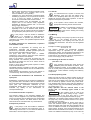
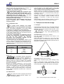
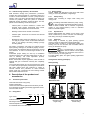
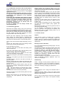
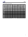
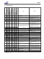
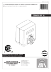
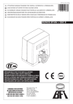
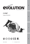
KSB RPH-V
Operating Instructions
Nº A1316.8.3E/1
Vertical Process Pump
according to API 610
as per Directive 94/9/EC
Works Nº: ________________________________
Type series: ______________________________
These
operating
fundamental
precautionary
notes.
instructions
information
Please
read
contain
and
the
manual
thoroughly prior to installation of unit, connection to
the
power
supply
and
commissioning.
It
is
imperative to comply with all other operating
instructions referring to components of this unit.
This manual shall always be kept close to
the unit´s location of operation or directly
on the pump set.
KSB Bombas Hidráulicas SA
Rua José Rabello Portella, 400
Várzea Paulista SP 13220-540
Brazil
http://www.ksb.com
phone.: 55 11 4596 8500 Fax: 55 11 4596 8580
SAK – KSB Customer Service
e-mail: [email protected]
Fax: 55 11 4596 8656
RPH-V
Contents
Page
1
2
2.1
2.2
2.3
2.4
2.5
2.6
2.7
2.8
2.9
2.9.1
2.9.2
2.9.3
2.9.4
2.9.5
2.9.6
3
3.1
3.2
4
4.1
4.2
4.3
4.3.1
4.3.2
4.3.3
4.3.4
4.3.5
4.3.6
4.3.7
4.4
4.5
5
5.1
5.2
5.2.1
5.3
5.4
5.5
5.5.1
5.6
5.6.1
5.6.2
5.7
General
Safety
Marking of Instructions in the manual
Personnel qualification and training
Non-compliance with safety instructions
Safety awareness
Safety instructions for the operator / user
Safety instructions for maintenance,
inspection and installation work
Unauthorized modification and manufacture
of spare parts
Unauthorized modes of operation
Explosion protection
Unit fill
Marking
Checking the direction of rotation
Pump operating mode
Temperature limits
Maintenance
Transport and interim storage
Transport
Interim storage (indoors) / preservation
Description of the product an
accessories
Technical specification
Designation
Design details
Pump casing
Impeller form
Shaft seal
Bearings
Permissible forces and moments at the
discharge nozzle
Noise characteristics
Technical data table
Accessories
Dimensions and Weights
Installation at site
Safety regulations
Checks to be carried out prior to installation
Place of installation
Soleplate foundation, settle and leveling
On a nozzle of a pressure vessel
Aligning the pump / drive
Aligning the complete unit
Connecting the piping
Auxiliary connections
Contact guard
Final check
4
4
4
4
4
4
4
5
5
5
5
5
5
5
5
6
6
6
6
7
7
7
7
7
7
7
7
8
8
8
9
9
9
9
9
9
9
9
10
10
10
10
11
11
11
5.8
6
6.1
6.1.1
6.1.2
6.1.3
6.1.4
6.1.5
6.1.6
6.1.7
6.2
6.2.1
6.2.2
6.2.3
6.2.4
6.2.5
6.3
6.3.1
6.3.2
6.4
7
7.1
7.2
7.2.1
7.2.2
7.3
7.4
7.4.1
7.4.2
7.4.3
7.5
7.5.1
7.5.2
7.5.3
7.5.4
7.5.5
7.5.6
7.6
7.6.1
7.6.2
8
9
Connection to power supply
Commissioning, start-up / shutdown
Commissioning
Lubricants
Shaft seal
Priming the pump and checks to be
carried out
Checking the direction of rotation
Cleaning the sump or pressure vessel
Start-up
Shutdown
Operating limits
Temperature of the fluid handled, ambient
temperature, bearing temperature
Switching frequency
Density of fluid pumped
Abrasive fluids
Minimum / maximum flow
Shutdown / storage / preservation
Storage of new pumps
Measures to be taken for prolonged
shutdown
Returning to service after storage
Servicing / Maintenance
General instructions
Servicing / inspection
Supervision of operation
Lubrication and lubricant change
Drainage / disposal
Dismantling
Fundamental instructions and
recommendations
Dismantling (general)
Check of wears
Reassembly
General instructions
Re-assembly (general) – below floor and
bearing bracket lantern
Shaft seal assembly
Reassembly (general) – above floor
Tightening torques
Diametral clearances
Spare parts stock
Recommended spare parts stock for 2
years’ operation
Interchangeability of pump components
Troubleshooting
Sectional drawing
11
11
11
11
12
12
12
13
13
13
13
13
13
13
13
14
14
14
14
14
14
14
14
14
15
15
15
16
16
16
17
17
17
17
18
18
19
19
19
20
21
22
RPH-V
Introduction
KSB has supplied you an equipment that has been designed and manufactured with the latest technology.
Due to its simple and tough construction, it will need few maintenance. With the aim to provide our clients with a
satisfactory, trouble free operation, we recommend to install and care our equipment according to the instructions
contained in this service manual.
This manual has been prepared to inform the end user about construction and operation of our pumps, describing the
proper procedures for handling and maintenance.
We recommend that this manual should be handled by the maintenance supervision.
This equipment must be used at operation conditions for which it has been selected, such as: flow rate, total head, speed,
voltage, frequency and temperature of pumped liquid.
Field for
description of
pump size and
type
Field for
technical
data
Field for
Production Order
Nº (P.O.)
Fig. 1 - Nameplate
For requests about the equipment, or when ordering spare parts, please mention the type of the pump and
the Production Order number (serial nº). This information can be obtained from the nameplate of each
pump. If the nameplate is not available, the OP number is engraved in low relief on the suction flange and
on the discharge flange you may find the impeller diameter.
Attention:
This manual contains very important recommendations and instructions. Must be carefully read
before installation, electrical connection, first start up and maintenance.
3
RPH-V
1. General
This KSB product has been developed
in accordance with state-of-the-art
technology; it is manufactured with utmost care and
subject to continuous quality control.
These operating instructions are intended to facilitate
familiarization with the unit and its designated use.
The manual contains important information for reliable,
proper and efficient operation. Compliance with the
operating instructions is of vital importance to ensure
reliability and a long service life of the unit and to avoid
any risks.
These operating instructions do not take into account
local regulations; the operator must ensure that such
regulations are strictly observed by all, including the
personnel called in for installation.
This pump / unit must not be operated beyond
the limit values for the fluid handled, capacity,
speed, density, pressure, temperature and motor
rating specified in the technical documentation. Make
sure that operation is in accordance
with
the
instructions laid down in this manual or in the
contract
documentation. Contact the manufacturer, if
required.
The nameplate indicates the type series / size, main
operating data and works number; please quote this
information in all queries, repeat orders and particularly
when ordering spare parts.
If you need any additional information or instructions
exceeding the scope of this manual or in case of damage
please contact KSB´s nearest customer service centre.
For noise characteristics please refer to section 4.3.7.
and special instructions concerning explosion protection
are marked
Caution
2. Safety
The word
Caution
is used to introduce safety instructions whose nonobservance may lead to damage to the machine and its
functions.
Instructions attached directly to the machine, e.g.
arrow indicating the direction of rotation
markings for fluid connections
must always be complied with and be kept in a perfectly
legible condition at all times.
2.2 Personnel qualification and training
All personnel involved in the operation, maintenance,
inspection and installation of the unit must be fully
qualified to carry out the work involved.
Personnel responsibilities, competence and supervision
must be clearly defined by the operator. If the personnel
in question is not already in possession of the requisite
know-how, appropriate training and instruction must be
provided. If required, the operator may commission the
manufacturer / supplier to take care of such training. In
addition, the operator is responsible for ensuring that the
contents of the operating instructions are fully understood
by the responsible personnel.
2.3 Non-compliance with safety instructions
These operating instructions contain fundamental
information which must be complied with during
installation, operation, monitoring and maintenance.
Therefore this operating manual must be read and
understood both by the installing personnel and the
responsible trained personnel / operators prior to
installation and commissioning, and it must always be
kept close to the location of operation of the machine /
unit for easy access.
Not only must the general safety instructions laid down in
this chapter on “Safety” be complied with, but also the
safety instructions outlined under specific headings,
particularly if the pump / unit is operated in hazardous
areas (see section 2.9).
Non-compliance with safety instructions can jeopardize
the safety of personnel, the environment and the machine
/ unit itself. Non-compliance with these safety instructions
will also lead to forfeiture of any and all rights to claims for
damages.
2.1 Marking of instructions in the manual
2.4 Safety awareness
The safety instructions contained in this manual whose
non-observance might cause hazards to persons are
specially marked with the symbol
general hazard sign to ISO 7000-0434
It is imperative to comply with the safety instructions
contained in this manual, the relevant national and
international explosion protection regulations, and the
operator´s own internal work, operation and safety
regulations.
Ex symbol relates to additional requirements
which must be adhered to when the pump is
operated in hazardous areas.
the electrical danger warning sign is
2.5 Safety instructions for the operator / user
In particular, non-compliance can, for example, result in:
failure of important machine / system functions;
failure of prescribed maintenance and servicing
practices;
hazard to persons by electrical, mechanical and
chemical effects as well as explosion;
hazard to the environment due to leakage of
hazardous substances.
safety sign to IEC 417-5036
Any hot or cold components that could pose a hazard
must be equipped with a guard by the operator.
4
RPH-V
-
-
-
Guards which are fitted to prevent accidental contact
with moving parts (e.g. coupling) must not be
removed whilst the unit is operating.
Leakages (e.g. at the shaft seal) of hazardous fluids
handled (e.g. explosive, toxic, hot) must be contained
so as to avoid any danger to persons or the
environment. All relevant laws must be heeded.
Electrical hazards must be eliminated. (In this
respect refer to the relevant safety regulations
applicable to different countries and / or the local
energy supply companies.)
Any components in contact with the fluid pumped,
especially in the case of abrasive fluids, shall be
inspected for wear at regular intervals and replaced
by original spare parts (see section 2.7) in due time.
If the pumps / units are located in hazardous
areas, it is imperative to make sure that
unauthorized modes of operation are prevented. Non–
compliance may result in the specified temperature limits
being exceeded.
2.6 Safety instructions for maintenance, inspection
and installation work
The operator is responsible for ensuring that all
maintenance, inspection and installation work be
performed by authorized, qualified specialist personnel
who are thoroughly familiar with the manual.
The pump must have cooled down to ambient
temperature, pump pressure must have been released
and the pump must have been drained.
Work on the machine / unit must be carried out only
during standstill. The shutdown procedure described in
the manual for taking the unit out of service must be
adhered to without fail.
Pumps or pump units handling fluids injurious to health
must be decontaminated.
Immediately following completion of the work, all safetyrelevant and protective devices must be re-installed and /
or re-activated.
Please observe all instructions set out in the chapter on
“Commissioning” before returning the unit to service.
2.9.1 Unit fill
It is assumed that the system of suction and
discharge lines and thus the wetted pump
internals are completely filled with the product to be
handled at all times during pump operation, so that an
explosive atmosphere is prevented.
If the operator cannot warrant this condition,
appropriate monitoring devices must be used.
In addition, it is imperative to make sure
that
the seal chambers, auxiliary
systems of the shaft seal and the heating and cooling
systems are properly filled.
Caution
2.9.2 Marking
The marking on the pump only refers to the pump
part, i.e. the coupling and motor must be
regarded separately. The coupling must have an EC
manufacturer’s declaration. The driver must be regarded
separately.
Example of marking on the pump part:
Ex II 2 G T1 - T5
The marking indicates the theoretically available
temperature range as stipulated by the respective
temperature classes. The temperatures permitted for the
individual pump variants are outlined in section 2.9.5.
Pumps RPH-V are designed to meet the requirements of
Zone 1 and Category 2 as per EN1127-1.
2.9.3 Checking the direction of rotation
(see also 6.1.4)
If the explosion hazard also exists during the
installation phase, the direction of rotation must
never be checked by starting up the unfilled pump unit,
even for a short period, to prevent temperature increases
resulting from contact between rotating and stationary
components.
2.9.4 Pump operating mode
2.7 Unauthorized modification and manufacture of
spare parts
Modifications or alterations of the equipment supplied are
only permitted after consultation with the manufacturer
and to the extent permitted by the manufacturer. Original
spare parts and accessories authorized by the
manufacturer ensure safety. The use of other parts can
invalidate any liability of the manufacturer for
consequential damage.
2.8 Unauthorized modes of operation
The warranty relating to the operating reliability and
safety of the unit supplied is only valid if the equipment is
used in accordance with its designated use as described
in the following sections. The limits stated in the data
sheet must not be exceeded under any circumstances.
2.9 Explosion protection
If the pumps / units are installed in hazardous
areas, the measures and instructions given in
the following sections 2.9.1 to 2.9.6 must be adhered to
without fail, to ensure explosion protection.
Make sure that the pump is always started up with the
suction-side shut-off valve fully open and the dischargeside shut-off valve slightly open. However, the pump can
also be started up against a closed swing check valve.
The discharge-side shut-off valve shall be adjusted to
comply with the duty point immediately following the runup process (see 6.1.7).
Pump operation with the shut-off valves in the
suction and / or discharge pipes closed is not
permitted.
this condition, there is a risk of the
Caution In
pump casing taking on high surface
temperatures after a very short time, due to a rapid
temperature rise in the pumped fluid inside the pump.
Additionally, the resulting rapid pressure build-up inside
the pump may cause excessive stresses on the pump
materials or even bursting.
The minimum flows indicated in section 6.2.5 refer to
water and water-like liquids. Longer operating periods
with these liquids and at the flow rates indicated will not
cause an additional increase in the temperatures on the
pump surface. However, if the physical properties of the
fluids handled are different from water, it is essential to
check if an additional heat build-up may occur and if the
5
RPH-V
minimum flow rate must therefore be increased. To
check, proceed as described in section 6.2.5.
In addition, the instructions given in section 6 of this
operating manual must be observed.
Both gland packings and mechanical seals
may exceed the specified temperature limits
if run dry. Dry running may not only result from an
inadequately filled seal chamber, but also from
excessive gas content in the fluid handled.
Pump operation outside its specified operating range
may also result in dry running.
In hazardous areas, gland packings shall only be
used if combined with a suitable temperature
monitoring device.
2.9.5 Temperature limits
In normal pump operation, the highest
temperatures are to be expected on the surface
of the pump casing, at the shaft seal and in the bearing
areas. The surface temperature at the pump casing
corresponds to the temperature of the fluid handled.
If the pump is heated, it must be ensured that the
temperature classes stipulated for the plant are observed.
In the bearing bracket area, the unit surfaces must be
freely exposed to the atmosphere.
In any case, responsibility for compliance with the
specified fluid temperature (operating temperature)
lies with the plant operator. The maximum
permissible fluid temperature depends on the
temperature class to be complied with.
The table below lists the temperature classes to EN
13463-1 and the resulting theoretical temperature limits of
the fluid handled. In stipulating these temperatures, any
temperature rise in the shaft seal area has already been
taken into account.
This also applies to the reliable function of the rolling
element bearings whose actual lifetime largely depends
on the operating mode and operating conditions.
Regular checks of the lubricant and the running noises
will prevent the risk of excessive temperatures as a result
of bearings running hot or defective bearing seals (also
see section 7.2.2.1).
The correct function of the shaft seal must be checked
regularly. Any auxiliary systems installed must be
monitored, if necessary, to make sure they function
correctly.
Gland packings must be tightened correctly, to prevent
excessive temperatures due to packings running hot.
3. Transport and interim storage
3.1 Transport
The transport of motor-pump set or only pump should be
made with ability and sound sense, according to safety
standards. By the motor eyebolt should only lift it, never
the motor-pump set.
If the pump / unit slips out of the suspension
arrangement, it may cause personal injury and
damage to property!
Assembled unity (Column up to 3 meters)
The unity should be transported and stored in the
horizontal position.
Lifting cable should be placed only in the pump casing
and drive lantern. To introduce the pump in the well,
place the lifting cables in the soleplate eyebolt and lift the
equipment to vertical position.
Temperature class to
Temperature limit of
EN 13463-1:
fluid handled
T5
85ºC
T4
120ºC
T3
185ºC
T2
280ºC
T1
Max. 400ºC *)
*) depending on material variant
Safety note:
The permissible operating temperature
of the pump in question is indicated on
the data sheet. If the pump is to be operated at a
higher temperature, the data sheet is missing or if the
pump is part of a pool of pumps, the maximum
permissible operating temperature must be inquired from
the pump manufacturer.
Based on an ambient temperature of 40ºC and proper
maintenance and operation, compliance with temperature
class T4 is warranted in the area of the rolling element
bearings. A special design is required to comply with
temperature class T6 in the bearing area. In such cases,
and if ambient temperature exceeds 40ºC, contact the
manufacturer.
Caution
Fig. 1 - Assembled unity
Single parts (column above 3 meters)
(Pump casing, suspension piping, shaft, bearings, rising
pipe).
Pump is transported partially disassembled, therefore
single parts should be transported and stored in the
horizontal position, except for drive lantern and soleplate.
2.9.6 Maintenance
Only a pump unit which is properly serviced and
maintained in perfect technical condition will
give safe and reliable operation.
Fig. 2 - Pump casing and part of column pipe
6
RPH-V
3.2
Interim storage (indoors) / Preservation
KSB standard storage and preservation procedures
maintain the pump protected for a maximum period of 6
months in a indoor installation. The unit / pump should be
stored in a dry room where the atmospheric humidity is as
constant as possible. When this period is exceeded,
additional storage procedure should be taken. For that,
please use the following conservation liquids:
-
Internal parts of ferrous material in contact with
pumped liquid (except mechanical seal contact
surfaces): water repellent of mineral oil basis.
-
Bearings: mineral oil for internal conservation.
-
Polished parts: mineral oil for internal and external
conservation.
-
Mechanical seals: should be cleaned by dry air. Do
not apply any liquid or other conservation material in
order to not damage secondary sealings (O´rings
and flat gaskets).
All existing connections, like plugs for external source
liquid, priming, drainage, etc, should be properly covered.
Pump suction and discharge flanges are properly covered
with adhesive, in order to avoid strange contents in its
interior.
Assembled pumps waiting for start up or installation
should have their rotor manually rotated each 15 days. In
case of difficulty, use some adjustable spanner,
protecting the motor shaft surface.
Before conservation liquids application, areas should be
washed with gas or kerosene until they are completely
cleaned.
The conservative liquids can be removed from the areas
in contact with pumped liquid, polished parts and surfaces
like: shaft, salient faces and couplings, by means of
solvents derived from petroleum or clean industrial
liquids. Drain the conservative oil from bearing bracket
before fulfill it with lubricant oil.
4.3 Design details
Vertical, radially split shaft-driven sump pump with volute
casing, in wet or dry installation, single stage.
4.3.1
Pump casing
Radially split, consisting of single volute casing and
casing cover.
For handling combustible media, the pump casing,
the pipe assembly and the flanged elbow must be
made of ductile material with a maximum magnesium
content of 7.5% (see EN 13463-1). This is a standard
feature in all KSB supplies.
4.3.2
Impeller form
Closed radial impeller with multiply curved vanes. Axial
thrust is balanced by means of suction and dischargeside casing wear rings and balancing holes.
4.3.3
Shaft seal
Shaft sealing is effected by gland packing (special
variant) or single or double acting mechanical seals.
The shaft seal is located in a replaceable stuffing box
housing and can be removed and re-installed without
having to dismantle the pump.
Caution
It is recommended to use sealing
plans with an external source (plans
32,52,53,54) to lubricate the mechanical seal faces in
order to avoid dry run during start-up.
For other sealing plans and gland packing applications
consult KSB.
Arrangement drawing (examples)
Gland packing
4. Description of the product and
accessories
4.1
Technical specification
Mechanical seal
Chemical shaft-driven sump pump
Fields of application:
Used in the chemical and petrochemical industry as well
as in refineries for handling chemically aggressive media
with low solids content.
4.2
Designation
RPH - V
40 - 180
Type series
Vertical execution
Discharge nozzle DN
Mechanical seal
single-acting
Mechanical seal
double-acting
Nominal impeller dia. in mm
For materials refer to the data sheet.
7
RPH-V
4.3.4
Bearings
The shaft assembly is fixed in axial direction by means of
a deep groove ball bearing. The bearing can be oil or
grease lubricated.
In the volute casing and in the pipe assemblies the shaft
is supported in plain bearings lubricated by the pumped
liquid. If contaminated fluids are handled, the bearings
can be lubricated from an external source via a lubricating
line (special design).
4.3.5
Permissible forces and moments at the
discharge nozzle
RPH-V pumps are designed in such way that they can
withstand piping forces and moments acc. to API 610.
The data on forces and moments apply to static pipelines
only. If the limits are exceeded, they must be checked
and verified.
The values are only applicable if the pump is installed on
a completely grouted soleplate.
4.3.6
Rated
power
input
PN
(kW)
1.5
2.2
3.0
4.0
5.5
7.5
11.0
15.0
18.5
22.0
30.0
37.0
45.0
55.0
75.0
90.0
110.0
Noise characteristics
Sound pressure level L pA (db) c d
Pump only
Pump with motor
2900
1/min
1450
1/min
960/760
1/min
2900
1/min
1450
1/min
960/760
1/min
53.5
55.5
57.0
58.5
60.5
62.0
64.0
65.5
66.5
67.5
69.0
70.0
71.0
72.0
74.0
75.0
76.0
51.5
53.5
55.5
57.0
58.5
60.0
62.0
63.5
65.0
66.0
67.5
68.5
69.5
70.5
72.0
73.0
74.0
50.5
52.5
54.0
55.0
56.5
58.0
60.0
61.5
62.5
63.5
65.0
66.0
66.5
67.5
69.0
70.0
71.0
62.5
65.0
67.0
68.5
70.0
71.5
73.5
74.5
75.5
76.0
77.0
77.5
78.5
79.0
79.5
80.0
80.5
57.0
59.5
61.0
62.5
64.5
65.5
67.5
69.0
70.0
70.5
71.5
72.0
73.0
74.0
75.0
75.5
76.0
55.5
57.5
59.0
60.5
62.0
64.0
65.5
67.0
68.0
68.5
69.5
70.5
71.5
72.0
73.0
74.0
74.5
c Measured at a distance of 1m from the pump outline (as per DIN 45635
Part 1 and 24). Room and foundation influences have not been included.
The tolerance for these factors is 1 to 2 dB.
d Increase for 60 Hz operation
Pump without motor: --Pump with motor:
3500min-1:+3dB, 1750min-1: + 1dB, 1160min-1: ---dB
8
RPH-V
50-200
80-200
40-231
40-280
40-281
40-361
50-180
- Inlet diameter
mm
- Impeller maximum diam.
Sealing chamber size (Acc.to API 682 Table 1)
6
6
6.2
10,5
14
7.8
7.7
7.5
7.7
7.9
10.9
48
48
58
57
88
105
75
75
61
71
69
88
179
224
180
224
205
207
180
230
278
278
343
180
Simple
--
4
Bearing
6313
- in the sealing chamber
(D)
Shaft diameter
- in the bearing
50
65
mm
- in the coupling
32
- in the impeller
24
27
0.019
0.0321
n = 1450 rpm
28
47
n = 1750 rpm
33
56
- Maximum Value P/n1)
Driver
Motor maximum
power
n = 2900 rpm
kW /
rpm
kW
n = 3500 rpm
1)
4.4
55
93
67
112
The indicated values are for shaft material A434 4140 CL.BB and impeller in A216WCB & temperature < 100ºC. For other condition, please consult KSB.
Accessories
Coupling: flexible coupling
If a complete unit is supplied, coupling and coupling
guard are provided by the supplier.
Special accessories: as required
4.5
40-181
40-230
6
-- Outlet width
Impeller
40-180
Volute type
25-230
Pump Size
25-180
Technical data table
Unity
4.3.7
Dimensions and Weights
For dimensions and weights please refer to the general
arrangement drawing of the pump.
5. Installation at site
Pumps should be installed, leveled and aligned by
qualified people. When this service is inappropriate
executed, it can have as consequence, operation
troubles, premature wear and irreparable damage.
Foundation Plan drawing (FU) informs pump dimension,
weights, foundation arrangement, connection sizes and
position of fixation elements.
Assure that all parameters for handling and operation
(access, assembly area, connections for assembly
equipment, cranes, etc) were perfectly established before
pump installation activities.
5.1 Safety regulations
Equipment operated in hazardous locations
must comply with the relevant explosion
protection regulations. This is indicated on the pump
name plate and motor name plate (see 2.9).
5.2 Checks to be carried out prior to installation
In case of concrete foundations they shall have
sufficient strength (min.class X0) to ensure safe and
functional installation in accordance with DIN 1045 or
equivalent standards.
Make sure that the concrete foundation has set firmly
before placing the unit on it. Its surface shall be truly
horizontal and even. The foundation bolts shall be
inserted in the soleplate.
5.2.1 Place of installation
The volute casing, the pipe assembly and certain
areas of the soleplate take on roughly the same
temperatures as the medium handled. The motor stool or
bearing bracket lantern must not be insulated.
Take the necessary precautions to avoid burns.
5.3 Soleplate foundation, settle and leveling
Place foundation rail in the trench done in the foundation
block in accordance with Foundation Plan dimensions.
The foundation rail leveling should be executed with a
precision level instrument, and kept smaller than 0,1
mm/meter since its not recommended to place chock
blocks which would injure soleplate tightness. After
complete mortar cure it should executed an appropriate
cleaning and removed concrete sparkling from foundation
rail. Place the gasket and soleplate over foundation block
and fix it.
Note: The tightness of the well can affect the NPSHA due
to atmospheric pressure absence. The user should
assure that NPSHA is higher than NPSHR at least 1,0
meter.
Check if soleplate is uniform arranged on the foundation
rail.
All structural work required must have been prepared
in accordance with the dimensions stated in the
dimension table / general arrangement plan.
9
RPH-V
Fig. 5 - Aligning a spacer-type coupling
The radial and axial deviation between the two coupling
halves must not exceed 0.1 mm.
Fig. 3 - Soleplate settle
5.4 On a nozzle of a pressure vessel
In this case the pump set is supplied on a flange that will
cover / close the tank vessel.
Normal procedures recommended for flange connection
should be applied i.e. parallelism between the contact
faces smaller than 0,5 mm and leveling deviation smaller
than 0,1 mm/meter.
The alignment of the pump and drive shall preferably be
checked by means of a dial micrometer. For this purpose
remove the coupling spacer after having marked its
installation position by dotting marks (balancing
condition).
At the same time check the motor´s direction of rotation,
with the pump decoupled (see 6.1.4). The direction of
rotation must correspond to the direction indicated by the
arrow on the pump. Verify by switching the motor on and
then off again immediately. Fig. 6 illustrates examples of
possible dial micrometer arrangements.
5.5 Aligning the pump / drive
The pump unit consisting of pump, coupling and drive has
been mounted on a common baseplate and carefully
aligned in the manufacturing works.
The following instructions also apply to units not mounted
on a common baseplate.
connecting the piping and priming
Caution After
the system, it is essential to re-check
the alignment at operating temperature.
Incorrect alignment and inadmissible
coupling displacement will affect the
operating behavior and may result in damage to the
bearings and shaft seals as well as premature coupling
wear.
Please note:
The pump set is correctly aligned, if a straight-edge
placed axially on both coupling halves is the same
distance from each shaft at all points around the
circumference. In addition, the distance between the two
coupling halves must remain the same all around the
circumference. Use a feeler gauge, a wedge gauge or a
dial micrometer to verify (see figs. 4 and 5).
Caution
Fig. 6 - Aligning a spacer-type coupling with a dial
Micrometer
Admissible run-out of coupling face (axial) max. 0.1 mm.
Admissible radial deviation, measured over the complete
circumference, max. 0.2 mm.
5.5.1 Aligning the complete unit
To align the complete unit, undo bolt 901.4 and fixing
bolts 901.61 on the assembling aid (if any).
Undo pump fastening elements and align pump and
motor. (Compensate for any differences in height
between pump and motor by means of approximately
sized sheet packs under the feet of the drive). On pump
units with larger motors, horizontal motor alignment shall
be effected by means of alignment devices). Re-tighten
the bolts on the pump foot and the motor bolts.
If any, tighten fixing bolts 901.61 as well as bolt 901.4 and
re-check alignment. For subsequent alignment at
operating temperature proceed in the same way.
If other couplings are used, please refer to the enclosed
supplementary operating instructions.
5.6 Connecting the piping
Never use the pump itself as an
anchorage point for the piping. The
permissible pipeline forces must not be exceeded (see
section 4.3.5).
The pipelines shall be anchored in close proximity to the
pump and connected without transmitting any stresses or
Caution
Fig. 4 - Aligning the coupling with the help of a gauge and
a straight-edge
10
RPH-V
strains. The nominal diameters of the pipelines shall be at
least equal to the nominal diameters of the pump nozzles.
It is recommended to install check and shut-off elements
in the system, depending on the type of plant and pump.
It must be ensured, however, that the pump can still be
drained and dismantled without problems.
Thermal expansions of the pipelines must be
compensated by appropriate measures so as not to
impose any extra loads on the pump exceeding the
permissible pipeline forces and moments.
An excessive, impermissible increase in the
pipeline forces may cause leaks on the pump
where the fluid handled can escape into the atmosphere.
Danger of life when toxic or hot fluids are handled.
The flange covers on the pump suction and discharge
nozzles must be removed prior to installation in the
piping.
After the piping has been connected, it
must be easy to rotate the pump shaft by
hand at the coupling.
Caution
Recommendations for suction
In the pump installation, please consider the following
conditions:
a) Check minimum distance from bottom well up to
suction outlet or strainer according to installation (see
foundation plan).
b) Check liquid minimum level above pump casing, in
order to avoid dry operation, cavitation or vortex.
c) In case of frequent liquid level variation, it should
foreseen the installation of protection system against
operation below the minimum level.
5.6.2 Contact Guard
In compliance with the accident prevention
regulations the pump must not be operated
without a contact guard.
If the customer specifically requests not to include a
contact guard in our delivery, then the operator must
supply one. In this case, it is important to make sure that
the materials selected for coupling and coupling guard
are non-sparking in the event of mechanical contact.
KSB’s scope of supply meets this requirement.
5.7 Final check
Re-check the alignment as described in section 5.3 and
verify the correct distance between the coupling and the
coupling guard.
It must be easy to rotate the shaft by hand at the
coupling.
5.8 Connection to power supply
Connection to the power supply must be effected
by a trained electrician only. Check available
mains voltage against the data on the motor rating plate
and select appropriate start-up method.
We strongly recommend to use a motor protection device
(motor protection switch).
In hazardous areas, compliance with IEC6007914 is an additional requirement for electrical
connection.
6. Commissioning, start-up / shutdown
d) In case of liquid with solids in suspension or with
excessive dirty, it should foreseen strainer in the pump
inlet.
Compliance
with
the
following
requirements
is
of
paramount
importance. Damage resulting from non-compliance shall
not be covered by the scope of warranty.
Recommendations for discharge piping
6.1 Commissioning
The discharge piping assembly should comply with the
following considerations:
a) It should have disposals for water hammer control,
every time the overpressure values, deriving from liquid
return in long pipings, exceeds the recommended values
for piping and pump.
Before starting up the pump make sure that the following
requirements have been checked and fulfilled.
If a constant-level oiler is provided, screw same into the
tapping hole provided in the bearing bracket prior to
adding the oil (see 6.1.1).
The connection between bearing bracket and constantlevel oiler shall be sealed with PTFE tape, if necessary.
The operating data, the oil level, if applicable (6.1.1), and
the direction of rotation (6.1.4) must have been checked.
The pump must have been primed (6.1.3).
Also verify the following:
Make sure that the unit has been properly connected
to the electric power supply and is equipped with all
protection devices.
Make sure that all auxiliary lines (5.4.1) are
connected and functioning.
If the pump has been out of service for a longer
period of time, proceed in accordance with section
6.4.
b) In the points where it is necessary to extract the air it
should foreseen vent valves.
c) It is necessary to foreseen tie bolted assembly joints, to
absorb system reaction efforts, deriving from applicable
loads.
d) Safety valves, relief disposals and other operation
valves, besides those mentioned, should foreseen when
necessary.
5.6.1 Auxiliary connections
The dimensions and locations of the auxiliary
connections (cooling, barrier liquid, flushing liquid, etc.)
are indicated on the general arrangement drawing or
piping layout.
These connections are required for proper
Caution functioning of the pump and are therefore
of vital importance!
Caution
6.1.1 Lubricants
Oil lubricated bearings
The bearing bracket has to be filled with lubricating oil.
The oil quality required is outlined in section 7.2.2.3 and
the quantity in section 7.2.2.4.
11
RPH-V
For external liquid supply, the quantities
and pressure specified in the data sheet
and general arrangement drawing shall be applied.
Caution
6.1.3 Priming the pump and checks to be carried out
Before start-up, the pump, suction line and thermosyphon
vessel, if any, must be vented and primed. The shut-off
valve in the suction line must be fully open.
Fully open all auxiliary lines provided (flushing, barrier,
cooling liquid, etc.) and check the throughflow.
For water cooling, use suitable non-aggressive cooling
water not liable to form deposits and not containing
suspended solids. (Hardness: on average 5dH; (~1
mmol/l); pH > 8, or conditioned and neutral with regard to
mechanical corrosion).
Inlet temperature tE = 10 to 30ºC
Outlet temperature tA max. 45ºC
Fig. 7 - Oil fill
Procedure:
Remove the protective cage of the constant-level oiler.
Unscrew vent plug. Pour in the oil through the vent plug
tapping hole after having hinged down the reservoir of the
constant-level oiler until oil appears in the vertical portion
of the connection elbow (Fig 7).
Then fill the reservoir of the constant-level oiler with oil
and snap it back into operating position. Screw vent plug
in again. After a short time check whether the oil level in
the reservoir has dropped. It is important to keep the
reservoir properly filled at all times!
If access to the vent plug is difficult or impossible, e.g. in
cases where the motor is arranged above the pump
(piggy-back arrangement), the oil can be filled in through
the connection elbow of the constant-level oiler.
The oil level shall always be below the
Caution level of the vent opening arranged at
the top edge of the connection elbow.
During pump standstill the oil level can be checked at the
oil level sight glass.
Grease lubricated bearings
This option provides a bearing sealed on both sides and
lubricated for life with a special grease (ref. SKF – GJN).
For replacements consider this characteristic.
6.1.2 Shaft seal
Gland packings supplied with the pump
have to be installed prior to pump startup
(unless they were fitted prior delivery).
The gland packing must be tightened gently and evenly.
It must be easy to rotate the shaft by hand.
Caution
The mechanical seal has been fitted prior
to delivery. On variants with quench
supply tank, the tank must be fitted in accordance with
the general arrangement drawing (see also 6.1.3).
Quench feed must also be provided during pump
shutdown. On variants with pressurized dual mechanical
seals, apply barrier pressure as specified in the general
arrangement drawing prior to starting up the pump (see
6.1.3). Barrier pressure must also be provided during
pump shutdown.
Caution
Caution
Dry running of the pump will result in
mechanical seal failure and must be
avoided!
6.1.3.1 Cooling
In general, the shaft seal must be cooled
if the vaporization pressure of
the fluid handled is higher than the atmospheric pressure.
Depending on the fluid handled, the system pressure and
the mechanical seal material, the limit may change
(example: hot water).
Caution
Caution
Observe permissible temperature
classes.
6.1.4 Checking the direction of rotation
When the unit has been connected to the electric power
supply, verify the following (local and national regulations
have to be taken into account separately):
For trouble-free operation of the pump,
Caution the
correct direction of rotation of the
impeller is of paramount importance. If running in the
wrong direction of rotation, the pump cannot reach its
duty point; vibrations and overheating will be the
consequence. The unit or the shaft seal might be
damaged.
Correct direction of rotation:
The direction of rotation must correspond to the direction
indicated by the arrow on the pump.
Never put your hands or any other objects into the
pump.
The motor’s direction of rotation
must be checked with the
pump/motor coupling removed.
If the motor runs in the wrong direction of rotation,
interchange two of the three phases in the control cabinet
or motor terminal box.
The safety instructions set forth in section 2.9.3 must be
complied with.
Caution
12
RPH-V
6.1.7 Shutdown
Fig. 8 – Decoupled drive
6.1.5 Cleaning the sump or pressure vessel
The cleaning operation mode and duration for
flushing and pickling service must be matched to
the casing and seal materials used.
6.1.6 Start-up
Before starting the pump ensure that the shut-off element
in the suction line (if any) is fully open.
The pump may be started up against a closed dischargeside swing check valve or slightly open shut-off valve.
Only after the pump has reached full rotational speed
shall the shut-off valve in the discharge line be opened
slowly and adjusted to comply with the duty point. When
starting up against an open discharge-side shut-off valve,
take the resulting increase in input power into account!
Pump operation with the shut-off
valves in the discharge and
suction pipes closed is not permitted.
The permissible pressure and temperature limits might be
exceeded. In extreme cases, the pump may burst.
After the operating temperature has
Caution
been reached and / or in the vent of
leakage, switch off the unit and re-tighten the bolts
between volute casing and casing cover. Permissible
tightening torques see 7.5.3.
Check the coupling alignment at
Caution
operating temperature as described in
section 5.3.1 and re-align, if necessary.
Caution
Immediate steps after start up
After start up and with pump in process, please observe
the following items:
a) Control electric power consumption (amperage) and
voltage;
b)
Certify that the pump runs free of vibration and
abnormal noises;
c)
Control support bearing temperature, which can
reach up to 40ºC above ambient temperature,
however the sum of them can not exceed 82ºC.
The above items should be controlled each 15 minutes
during the first 2 hours operation. If everything is normal,
new controls should be made each 1 hour, during the first
5 up to 8 hours. If there is anything abnormal during this
period, please consult chapter Functioning Abnormalities
and its eventual Causes.
Close the shut-off valve in the discharge line.
If the discharge line is equipped with a non-return or
check valve, the shut-off valve may remain open. If shutoff is not possible, the pump will run in reverse direction.
may cause damage to mechanical
Caution This
seals which are not bi-directional!
The reverse runaway speed must be lower than the rated
speed.
Switch off the drive, making sure that the unit runs down
smoothly to a standstill.
Close the auxiliary lines but do not turn off the cooling
liquid supply, if any, until the pump has cooled down.
Please refer to section 6.1.2!
In the event of frost and / or prolonged shutdowns, the
pump – and the cooling chambers, if any – must be
drained or otherwise protected against freezing.
6.2 Operating limits
The pump´s / unit´s application limits regarding
pressure, temperature and speed are stated on
the data sheet and must be strictly adhered to!
If a data sheet is not available, contact KSB!
6.2.1 Temperature of the fluid handled, ambient
temperature, bearing temperature
Do not operate the pump at temperatures
exceeding those specified
on the data sheet or the name plate unless the written
consent of the manufacturer has been obtained.
Damage resulting from disregarding this warning will not
be covered by the KSB warranty.
Bearing bracket temperature see 7.2.1.
The safety instructions set forth in section 2.9 must
be complied with.
Caution
6.2.2 Switching frequency
To prevent high temperature increases in the motor and
excessive loads on the pump, coupling, motor, seals and
bearings, the switching frequency shall not exceed the
following number of start-ups per hour (S).
Motor rating (kW)
max. S (start –ups / h)
up to 12
15
up to 100
10
more than 100
5
If the above switching frequencies are exceeded, please
contact the motor manufacturer or KSB.
6.2.3 Density or fluid pumped
The power input of the pump will increase in proportion to
the density of the fluid pumped. To avoid overloading of
the motor, pump and coupling, the density of the fluid
must comply with the data specified on the purchase
order.
6.2.4 Abrasive fluids
When the pump handles liquids containing abrasive
substances, increased wear of the hydraulic system and
13
RPH-V
the shaft seal are to be expected. The intervals
recommended for servicing and maintenance shall be
shortened.
advisable to close the pump nozzles (e.g. with
plastic caps or similar).
6.4 Returning to service after storage
6.2.5 Minimum / Maximum flow
For max. flow Qmax please refer to the characteristic
curves. Unless other limits are specified in the
characteristic curves or data sheet, the minimum flow for
50 Hz and ρ = 1.2 kg / dm3
3
60 Hz and ρ = 1.0 kg / dm
is Qmin = 0.3 x Qopt
Qopt = optimum efficiency
The data refer to water and water-like liquids. However, if
the physical properties of the fluids handled are different
from water, the calculation formula below must be used to
check if an additional heat build-up may lead to a
dangerous temperature increase at the pump surface. If
necessary, the minimum flow must be increased.
To = Tf + ∆ ϑ
∆ ϑ = g * H / c * η * (1 - η )
c
g
H
Tf
To
η
∆ϑ
Specific heat
Acceleration due to gravity
Pump head
Temperature of fluid handled
Temperature of casing surface
Pump efficiency at duty point
Temperature difference
[ J / kg K ]
2
[m/s ]
[m]
[ ºC ]
[ ºC ]
[-]
[ ºC ]
6.3 Shutdown / storage / preservation
Each KSB pump leaves the factory carefully assembled.
If commissioning is to take place some time after delivery,
we recommend that the following measures be taken for
pump storage.
6.3.1 Storage of new pumps
-
New pumps are supplied by our factory duly
prepared for storage. Maximum protection for up to 6
months, if the pump is properly stored indoors.
Store the pump in a dry location.
Rotate the shaft by hand once a month.
6.3.2 Measures to be taken for prolonged shutdown
1.
2.
The pump remains installed; periodic check of
operation
In order to make sure that the pump is always ready
for instant start-up and to prevent the formation of
deposits within the pump and the pump intake area,
start up the pump set regularly once a month or once
every 3 months for a short time (approx. 5 minutes)
during prolonged shutdown periods.
Prior to an operation check run ensure that there is
sufficient liquid available for operating the pump.
The pump is removed from the pipe and stored
Before putting the pump into storage, carry out all
checks specified in sections 7.1 to 7.4. Then apply
appropriate preservatives:
Spray-coat the inside wall of the pump casing,
and in particular the impeller clearance areas,
with a preservative. Spray the preservative
through the suction and discharge nozzles. It is
Before returning the pump to service, carry out all checks
and maintenance work specified in sections 7.1 and 7.2.
In addition, the instructions laid down in the
sections on “ Commissioning “ 6.1)
and
“ Operating Limits “ (6.2) must be observed.
Immediately following completion of the work, all
safety-relevant and protective devices must be
re-installed and / or re-activated.
7. Servicing / maintenance
7.1 General Instructions
The operator is responsible for ensuring that all
maintenance, inspection and installation work be
performed by authorized, qualified specialist personnel
who are thoroughly familiar with the manual.
A regular maintenance schedule will help avoid expensive
repairs and contribute to trouble-free, reliable operation of
the pump with a minimum of maintenance expenditure
and work.
Work on the unit must only be carried out
with the electrical connections disconnected.
Make sure that the pump set cannot be switched on
accidentally (danger to life!).
Pumps handling liquids posing health
hazards must be decontaminated. When
draining the fluid see to it that there is no risk to
persons or environment or the environment. All
relevant laws must be adhered to (danger to life)!
7.2 Servicing / inspection
7.2.1 Supervision of operation
The pump must run quietly and free
from vibrations at all times.
The pump must never be allowed to run dry.
Always ensure a sufficient liquid level above the pump
inlet.
Prolonged operation against a closed shut-off
valve is not permitted. When operating the pump
set with the shut-off valve in the discharge line slightly
open for a short period of time, the permissible pressure
and temperature limits must not be exceeded.
A special design is required to comply with
temperature class T6 in the bearing area. In
such cases, and if ambient temperature exceeds 40ºC,
contact the manufacturer.
Verify correct oil level as described in section 6.1.1.
The shut-off elements and the auxiliary feed lines must
not be closed during operation.
Any stand-by pumps installed shall be started up
regularly, e.g. once a week, to keep them operational.
Attention shall be paid to the correct functioning of the
auxiliary connections. The cooling system must be
thoroughly cleaned at least once a year to ensure proper
cooling. Take the pump out of service for this purpose.
If the flexible coupling elements begin to
Caution
show signs of wear, they must be
replaced in due time. Re-align the coupling as described
in section 5.3.1.
Caution
14
RPH-V
Supervision during Operation
Caution
Depending on the labor availability and pump
responsibility, we recommend the following checks, and
in case of any abnormality the maintenance responsible
should be advised immediately.
Please observe the local
laws
applicable to the disposal of such
substances.
7.2.2.3 Oil quality
Monthly Supervision
Check:
Lubricating oil CLP46
DIN 51517
or HD 20W/20 SAE
Symbol to DIN 51502
Kinematic viscosity at 40 º C
46 +/- 4 mm2/s
Flash point (to Cleveland)
+ 175 º C
Solidification point (pour
- 15 º C
point)
higher than permissible
Application temperature *)
bearing temperature
*) For ambient temperatures below – 10º C another
suitable lubricating oil type must be used.
Request particulars.
a)
7.2.2.4 Oil quantity: 0,75 l.
Weekly Supervision
Check:
Designation
a)
Pump operation point;
b)
Motor current consumption and net tension value;
c)
Vibration and abnormal noises;
d)
Bearing housing temperature.
Grease change interval, (if applicable).
Semestral Supervision
Check:
7.2.2.5 Guide bearings
a)
Soleplate and motor fix bolts;
b)
Pump-motor set alignment;
c)
Coupling lubrication (when applicable).
In the volute casing and the pipe assemblies the shaft is
guided by plain bearings lubricated by the pumped liquid.
Periodically, user should check and clean the small holes
of lubricating pipes to the column bearings and
mechanical seal.
The small holes should not be
Caution
clogged !!
Annual Supervision
Disassemble the pump for maintenance. After cleaning,
inspect bearings, (do it in detail), retainers and / or
bearing sealings, joints, O´rings, impeller, split casing
internal regions (control also thickness), wear areas and
coupling.
If the pumped liquid is contaminated, the bearings are
lubricated from an external source via a lubricating line
(special design).
7.3 Drainage / disposal
Note:
In installations with good operation conditions and
pumped liquid not aggressive to the pump materials, the
supervision can be done each 2 years.
7.2.2 Lubrication and lubricant change
7.2.2.1 Lubrication
The rolling element bearings are lubricated with mineral
oil or grease for life. The guide bearings are lubricated
with the pumped fluid. The lubricant change intervals as
well as the required quantity and quality are specified
below.
7.2.2.2 Oil change (operating hours)
First oil change
7.4 Dismantling
at the bearing
after ....
operating hours
All subsequent oil
changes after....
operating hours
up to 70 º C
300
8500 *)
70 º C - 80º C
300
4200 *)
300
2000 *)
Temperature
80º C - 90º C
*) at least once a year
If the pump was used for handling liquids
posing health hazards, see to it that
there is no risk to persons or the environment when
draining the fluid. All relevant laws must be heeded. If
required, wear safety clothing and a protective mask!
If the fluids handled by the pumps leave residues which
might lead to corrosion when coming into contact with
atmospheric humidity, or which might ignite when coming
into contact with oxygen, then the unit must be flushed
through, neutralized, and then for drying purposes
anhydrous gas must be blown through the pump.
The flushing fluid used and any liquid residues in the
pump must be properly collected and disposed of without
posing any risk to persons or the environment.
Caution
Procedure:
Remove screwed plug below the bearing bracket and
drain off the oil. After drainage of the bearing bracket,
screw in the plug again and fill with fresh oil as described
in section 6.1.1.
Before dismantling the pump, secure it so as to
make sure it cannot be switched on accidentally.
The shut-off valve in the discharge line must be closed.
The pump set must have cooled down to
ambient temperature, pump pressure must
have been released and the pump must have been
drained including oil of bearing housing, if any.
Dismantling and reassembly must always be carried
out in accordance with the relevant sectional
drawing.
15
RPH-V
7.4.1 Fundamental instructions and recommendations
Repair and maintenance work to the pump must only be
carried out by specially trained personnel, using original
spare parts (see 2.7).
Observe the safety regulations laid down in section
7.1. Any work on the motor shall be governed by the
specifications and regulations of the respective
motor supplier.
Dismantling and reassembly must always be carried
out in accordance with the relevant general assembly
drawing. The general assembly drawing and other
relevant documents are found in the annex. The
dismantling sequence can be derived from the
general assembly drawing.
In case of damage you can always contact our
service departments.
7.4.2 Dismantling (general)
Disconnect the auxiliary piping (if any) and remove the
pump set and soleplate or flange from the sump or tank.
Put it on the horizontal position. Remove coupling guard.
Disconnect the coupling and remove the motor. Extract
the half coupling of pump shaft, loosening the sleeve
fixing bolt before. Take out the key (940.1).
Before loosening the suspension piping (713.1) from
soleplate (893) or flange, sustain the pump on a piece of
wood. Remove the nuts (920.18) and loosen the soleplate
with auxiliary of a crane.
Loosen the suspension piping (713.1) with the spider
bearings (383). Proceed removing the suspension piping
(731), extracting the intermediary shaft (212) and the
pump shaft (211) which are coupled together with a split
coupling (853). Remove the bearing sleeves (529) from
the shaft, which are radially fixed by means of grub
screws (904).
Separate the volute casing (102) from pressure cover
(163) and remove pump shaft (211), together with the
impeller (230).
Take out spiral wound gasket (411.31), loosen impeller
nut (922) and remove impeller (230), together with
gaskets (411).
Remove the key (940.5), the seal ring (400.33) and the
shaft protective sleeve (524).
If it is necessary to disassemble the bearing bush
(545.27) of pressure cover (163) use an extractor. The
bearing bush (545) of spider bearing (383) can be
removed by means of a press.
7.4.3 Check of wears
Impeller
Remove the motor loosening it from the drive lantern
(341). Extract the washer (920.17), unfastening the
soleplate (893) from the foundation rail (89-8). Remove
the pump from well and leave it in the horizontal position.
Take out the constant oil level (638) and piping (710.7), if
any.
Remove the drive lantern (341) from bearing bracket
lantern (344), loosening the bolts (901.9).
Extract the adjust nut (923.2).
Loosen the bolts (901.3) that fasten the bearing cover
(360), and remove it.
Extract the center sleeve (526), with the bearing (321),
using an extractor. Remove the key (940.2).
Loosen the bolts (901.11) to separate the drive shaft
(213) and intermediary coupling (848).
Loosen the bolts (901.5) and remove the bearing casing
(350).
Loosen the nuts (920.13) and take out the mechanical
seal (433).
For gland packing, undo hex. nuts 920.13 and take off
gland cover 452.
Remove packing rings 461, lantern ring 458 (if any) and
the packing rings behind the lantern ring from stuffing box
housing 451.02.
Remove the bearing bracket lantern (344) from the
soleplate (893) or flange, loosening the nuts (920.17) and
studs (902.17).
This action depends on seal plan piping / tubing
arrangement. Check before if any piping / tubing
will collide with it and remove them previously.
Remove the pipings (710), disconnecting them from their
connections (720).
Remove the rise piping (711) and discharge curve (144)
loosening the nuts (920.19) and bolts (901.33),
respectively.
Check damage caused to impeller due to corrosion,
cavitation or erosion, and if necessary replace the
impeller. When the clearance between the impeller and
casing wear rings reach the double of specified value,
replace them.
Bearings (Column and thrust)
Do not use disassembled rolling bearings again. Use only
specified bearings.
The clearances between the bearing sleeves (529), shaft
protective sleeve (524) and bearing bush (545) can not
exceed the values of 0,17 mm up to 0,3 mm. If
exceeding these values these parts should be changed.
Please observe methods of fixation of the bushes
indicated on cross sectional drawing. For certain bush
materials are necessary a bonding agent and grub
screws due to shrink characteristic.
Eventual machining in the sleeves can also be done, in
order to eliminate superficial defectives, since the
clearance is maintained.
Shaft Sealing
Check damage at shaft protective sleeve and if it is
possible, machine it, if not, it is necessary to replace it.
Check damage of mechanical seal rotative and stationary
faces and if necessary re-lapping or replace them.
Sealings
Check damages in the O’rings and substitute them if
necessary.
Substitute the flat gasket, O´rings and spiral wound
gasket. Certify that the new parts have the same size and
thickness of the old ones.
Note: In case of column above 3 meters, the pump should
be disassemble at the sump in the sequence already
described.
16
RPH-V
7.5 Reassembly
7.5.1 General instructions
The pump shall be reassembled in accordance with the
rules of sound engineering practice.
Clean all dismantled components and check them for
signs of wear. Verify the dimensions given in section
7.5.5. Damaged or worn components are to be replaced
by original spare parts. Make sure that the seal faces
are clean and that the sealing elements are properly
fitted.
Always use new sealing elements (O-rings / gaskets)
whenever the pump is reassembled. Make sure that new
gaskets have the same thickness as the old ones.
Gaskets made of graphite or other asbestos-free
materials must always be fitted without using lubricants
such as copper grease or graphite paste.
Avoid the use of mounting aids as far as possible. Should
a mounting aid be required after all, use a commercially
available contact adhesive (e.g. “Pattex”). The adhesive
shall only be applied at selected points (3 to 4 spots) and
in thin layers.
Do not use cyanoacrylate adhesives (quick-setting
adhesives)! If in certain cases mounting aids or antiadhesives other than described herein are required,
please contact the sealing material manufacturer.
All graphite gaskets must only be
used once!
Never use O-rings that have been glued together from
material sold by the metre.
Do no coat O-rings with graphite or
Caution
similar products. Use animal fats or
silicone-base or PTFE-base lubricants instead. O-rings
made of ethylene propylene shall only be coated with
silicone grease or soft soap; never use mineral oils or
greases!
The locating surfaces of the individual components must
be coated with graphite or similar before reassembly. The
same applies to screwed connections.
Caution
7.5.2 Reassembly (general) – below floor and bearing
bracket lantern
Flush off the intermediary shaft (212) against the pump
shaft (211) with placed split rings (501). Fix them with
split coupling (853) and studs (902.22).
Fasten the bearing bracket lantern (344) on the soleplate
(893) or flange.
Place the suspension piping (713.1) and bearing spider
(383.15), fixing them to the bearing bracket lantern (344)
and to the suspension piping (713.2).
Fix the rising pipe (711) on the soleplate or flange.
Connect the pipings (700) to the fittings (720).
7.5.3 Shaft seal assembly
Check the correct variant and proceed as below.
7.5.3.1 Mechanical seal installation
The following rules must be observed when mounting the
mechanical seal:
Extreme care and cleanliness during assembly are of
overriding importance for trouble-free operation of the
mechanical seal.
The protective wrapping of the contact faces shall only be
removed immediately before assembly takes place.
After inserting the seat ring, check whether it is planeparallel in relation to the casing part. (Max. deviation: 0.02
mm).
The surface of the shaft protecting sleeve must be
absolutely clean and smooth, and the sleeve’s mounting
edge must be chamfered. When sliding the rotating unit
onto the shaft protecting sleeve, take appropriate steps to
protect the shaft protecting sleeve’s surface from
damage.
On pumps with double-acting mechanical seal, the
mechanical seal chamber must be properly vented and
the required pressure specified in the installation plan
must be applied (also during standstill).
Quench liquid supply must also be ensured during pump
standstill.
7.5.3.2 Mounting the gland packing
Assemble the shaft protective sleeve (524), the sealing
ring (400.33), the key (940.5), the impeller (230), gaskets
(411) and impeller nut (922) at the pump shaft (211).
NOTE:
1) Change at every assembly the flat gaskets (400) and
O’ring (412).
2) The impeller nut (922) has the fixing system “helicoil”. For safety, KSB recommends replacement of it
each 3 or 4 disassembles.
Place the pump shaft set (211) in the spiral casing (102).
Place the pressure cover (163) with spiral wound
(411.31).
Assemble successively, the suspension piping (713.2),
the bearing sleeve (529.21) and bearing spider (383.21).
Always use pre-stressed packing rings, if possible.
Mount as follows:
Mount shaft protecting sleeve 524.02 (if any) onto the
shaft using grub screws 904.2.
Insert the first packing ring into the stuffing box housing.
Insert lantern ring 458 in such a way that the joint face is
offset from the cut edge of the packing ring. Insert other
packing rings with their cut edge displaced by 90º.
Slip on gland cover 452. Slightly tighten gland cover by
hand using the two hex. nuts 920.13.
Caution!
The gland packing has no contact with the liquid handled
and only seals against splashes and slight gas pressure.
Therefore the gland cover shall only be tightened slightly.
Dimensions of the packing chamber / number of packing
rings.
17
RPH-V
Put the outer spacer (504.1) into the bearing housing 350.
Mount the sub-assembly spacer sleeve + bearing into it.
Put the drive shaft (213) with key (940.2) inside the
spacer sleeve. Place the slip thrower (507), if any and
bearing guard on to the bottom bearing cover. Align it with
the intermediary coupling (848) and lock the ring (500).
Place the upper part of intermediary coupling spacer and
fix it with the bolts (901.12).
Place the flat gasket (400.3), the slip thrower (507), if any,
and bearing guard (423.1) and close the support bearing
with the upper bearing cover (360).
Before motor coupling adjust the axial clearance.
The axial clearance between impeller (230) and
pressure cover (163) must be adjusted, using the adjust
nut (923.2). For that, tight the nut until the impeller
touches the pressure cover.
With a depth caliper gauge with depth gauge and using
the reference surfaces of the shaft end and the adjust nut,
down the rotor in 2,5 mm.
7.5.4 Reassembly (general) - above floor
Place the half part of intermediary coupling (848) on the
last intermediary shaft end (212) using the key (940.3),
the washer (550.11) and the bolt (901.11).
Separately, pre-heat the bearing and inner spacer (504.2)
by induction or oil bath up to 80ºC and slide them on the
center sleeve (526).
Place the lock washer (931), screw the bearing nut (923),
tight and lock it with the lock washer. Fix the deflector
(508).
Fix the bottom bearing cover (360.1) or the bearing
casing (350) and gasket 400.5 to the bearing bracket
lantern (344).
Assemble the drive lantern (341) in the bearing bracket
lantern (344), with the bolts (901.9).
Place the key (940.1) and the bottom half coupling (840)
fixing it to the shaft with a grub screw.
Lift the pump set by the eye bolts (900.2) and place it on
the foundation rail (89-8), if any, fixing it with the bolts
(920.18). Couple the motor (801), fixing it to the drive
lantern (341).
Note: In the case of pumps with columns above 3 meters,
it should be assembled in the well and complying with the
sequence already described.
7.5.5 Tightening torques
DENOMINATION
PART Nº
PUMP SIZE
MATERIAL
25-180
25-230
40-180
40-230
50-200
80-200
40-280
40-181
40-231
40-281
40-361
50-180
Stud
(casing)
902.31
Stud
(cover)
901.29
Hex. Head Bolt
(bearing bracket)
901.3
Stud
(seal cover)
902.13
Steel A193 Gr. B7
SAE1045 8.8
Steel A193 Gr. B7
AISI 316
AISI 316
190
190
190
190
385
385
385
385
385
385
385
385
120
120
120
120
120
120
120
120
120
120
120
120
TORQUE (N.m)
40
40
40
40
40
40
40
40
40
40
40
40
50
50
50
50
50
50
50
50
50
50
50
50
80
80
80
80
130
130
130
130
130
130
130
130
Impeller nut
922
18
RPH-V
7.5.6 Diametral clearances
Pump size
Suction side
Casing wear ring
Nominal ID
Minimum
clearance gap
acc. to API 610
Clearance gap
acc. to AN 1501
Gr. 2 (standard)
Discharge side
Casing wear ring
Nominal ID
Minimum
clearance gap
acc. to API 610
Clearance gap
acc. to AN 1501
Gr. 2 (standard)
25-180
70
0,3
0,5
70
0,3
0,5
25-230
70
0,3
0,5
70
0,3
0,5
40-180
80
0,33
0,5
80
0,33
0,5
40-181
95
0,35
0,6
95
0,35
0,6
40-230
80
0,33
0,5
80
0,33
0,5
40-231
95
0,35
0,6
95
0,35
0,6
40-280
85
0,33
0,6
120
0,4
0,6
40-281
95
0,35
0,6
120
0,4
0,6
40-361
95
0,35
0,6
165
0,45
0,6
50-180
120
0,4
0,6
120
0,4
0,6
50-200
110
0,38
0,6
94
0,35
0,6
80-200
125
0,43
0,6
95
0,35
0,6
All the dimensions are in milimeters.
The performance curves are based on the standard clearances.
For any change in efficiency, please consult KSB.
7.6 Spare parts stock
When ordering spare parts, please indicate pump type and size, Production Order number, part name and number. These
information can be obtained from the Data Sheet, Sectional Drawings and Parts List.
7.6.1 Recommended Spare parts for a 2 years´ operation to DIN 24296.
PART N
º
DENOMINATION
2
NUMBER OF PUMPS (including stand-by pumps)
3
4
5
6
8
10 or more
Spare Parts Quantity
211/212/213
Shafts
1
1
2
2
2
3
30%
230
Impeller
1
1
2
2
2
3
30%
321
Bearing
1
1
2
2
3
4
50%
330
Bearing bracket
-
-
-
-
-
1
2 parts
383
Spider bearing
1
1
2
2
2
3
30%
411.31
Spiral wound
4
6
8
8
9
12
150%
423
Bearing guard
1
1
2
2
3
4
50%
433
Mechanical seal
1
1
1
2
2
2
20%
461 c
Gland packing (set)
4
4
6
6
6
8
100%
502
Casing wear ring
2
2
2
3
3
4
50%
503
Impeller wear ring
2
2
2
3
3
4
50%
524
Shaft protective sleeve
1
1
1
2
2
2
20%
529
Bearing sleeve
1
1
2
2
3
4
50%
545
Bearing bush
1
1
2
2
3
4
50%
840
Coupling
1
1
2
2
2
3
30%
---
Gaskets and O’rings
4
6
8
8
9
12
150%
c If fitted
19
SPIRAL CASING
STRAINER
CASING COVER
PUMP SHAFT
INTERMEDIARY SHAFT
DRIVE SHAFT
IMPELLER
BEARING
BEARING BRACKET
LANTERN
BEARING CASING
BEARING COVER
BEARING SPIDER
BEARING SPIDER
SPIRAL WOUND
BEARING GUARD
BEARING GUARD
MECHANICAL SEAL
SUCTION WEAR RING
DISCHARGE WEAR RING
SUCTION IMPELLER
WEAR RING
DISCHARGE IMPELLER
WEAR RING
SHAFT PROTECTIVE
SLEEVE
INT COUPLING
SPLIT COUPLING
IMPELLER NUT
KEY
KEY
102
143
161
211
212
213
230
321
344
350
360
383.15
383.21
411.31
423.1
423.2
433
502.1
502.2
503.1
503.2
524
848
853
922
940.5
940.1
DESCRIPTION
25-180
1
1
1
1
1
1
1
1
1
1
1
1
1
1
1
2
1
1
1
1
1
1
1
1
1
1
1
25-230
2
1
2
1
1
1
2
1
1
1
1
1
1
2
1
2
1
1
1
1
1
1
1
1
1
1
1
40-180
3
2
1
1
1
1
3
1
1
1
1
1
1
1
1
2
1
2
2
2
2
1
1
1
1
1
1
40-230
4
2
2
1
1
1
4
1
1
1
1
1
1
2
1
2
1
2
2
2
2
1
1
1
1
1
1
50-200
5
3
3
1
1
1
5
1
1
1
1
1
1
3
1
2
1
3
8
3
8
1
1
1
1
1
1
80-200
6
4
4
1
1
1
6
1
1
1
1
1
1
3
1
2
1
4
6
4
6
1
1
1
1
1
1
40-280
7
2
5
2
1
1
7
1
1
1
1
1
1
4
1
2
1
5
7
5
7
2
1
1
2
2
1
40-181
8
2
1
2
1
1
8
1
1
1
1
1
1
1
1
2
1
6
6
6
6
2
1
1
2
2
1
40-231
9
2
2
2
1
1
9
1
1
1
1
1
1
2
1
2
1
6
6
6
6
2
1
1
2
2
1
40-281
10
2
5
2
1
1 10
1
1
1
1
1
1
4
1
2
1
6
7
6
7
2
1
1
2
2
1
40-361
11
2
6
2
1
1 11
1
1
1
1
1
1
5
1
2
1
6
9
6
9
2
1
1
2
2
1
50-180
12
3
1
2
1
1 12
1
1
1
1
1
1
1
1
2
1
7
7
7
7
2
1
1
2
2
1
PART
Nº
PUMP SIZE
RPH-V
7.6.2 Interchangeability of pump components
20
RPH-V
Excessive rise of
temperature inside the pump
Vibration during pump
operation
Excessive leakage at the
shaft seal
Leakage at the pump
Increase in bearing
temperature
Excessive pump discharge
pressure
Motor is overloaded
Pump delivers insufficient
flow rate
8. Troubleshooting
•
Pump delivers against an excessively high
discharge pressure.
Re-adjust duty point.
•
Excessively high back pressure.
Check plant for impurities. Increase the
speed (turbine, I.C. engine).
Pump or piping are not completely vented or
primed.
Vent and/or prime.
•
•
•
•
Supply line or impeller clogged.
•
Formation of air pockets in the piping.
•
•
•
Pump is warped or sympathetic vibrations in
the piping.
•
•
•
Suction head is too high / NPSH available
(positive suction head) is too low.
•
Increased axial thrust. 2)
Air intake at the shaft seal.
•
Reverse rotation
•
•
•
Motor is running on two phases only.
•
•
•
•
•
•
•
•
•
•
•
•
•
•
•
•
Speed is too low. 2)
Defective bearings.
Insufficient rate of flow.
Wear of internal pump parts.
Pump back pressure is lower than specified
in the purchase order.
Density or viscosity of the fluid pumped is
higher than stated in the purchase order.
Use of unsuitable materials.
Speed is too high.
Tie bolts/seals and gaskets.
•
Worn shaft seal.
•
Score marks or roughness on shaft
protecting sleeve.
•
Lack of cooling liquid or dirty cooling
chamber.
•
Vibrations during pump operation.
•
•
•
•
•
•
1)
2)
Remedy 1)
Cause
The unit is misaligned.
Insufficient or excessive quantity of lubricant
or unsuitable lubricant.
Non-compliance with specified coupling
distance.
Operating voltage is too low.
Rotor is out of balance .
Remove deposits in the pump and/or piping.
Alter piping layout. /Fit a vent valve.
Check pipeline connection and secure fixing
of pump; if required reduced the distance
between the pipe clamps. Fix the pipelines
using anti-vibration material.
Check / alter liquid level. /Fully open shut-off
valve in the suction head line. /Change
suction line, if friction losses in the suction
line are too high.
Check any strainers installed / suction
opening.
Observe permissible speed of pressure fall.
Correct rotor adjustment.
Fit new shaft seal.
Interchange two of the phases of the power
supply cable.
Replace the defective fuse. Check the
electric cable connections.
Increase speed.
Fit new bearings.
Increase the minimum rate of flow.
Replace worn components by new ones.
Adjust duty point accurately.
2)
Change the Material combination.
Reduce the speed. 2)
Tighten the bolts. /Fit new seals and
gaskets.
Fit new shaft seal.
Fit new shaft protecting sleeve. Fit new shaft
seal / check the balancing line.
Check the throttle bush / throttling sleeve
clearances.
Increase cooling liquid quantity. /Clean out
cooling chamber. /Purify / clean cooling
liquid.
Improve suction conditions. /Re-align the
pump. /Re-balance the impeller. /Increase
the pressure at the pump suction nozzle.
Check the coupling; re-align, if required.
Top up, reduce or change lubricant.
Correct distance according to the G.A.
Drawing.
Increase the voltage.
Clean the impeller. /Re-balance the impeller.
Pump pressure must be released before attempting to remedy faults on parts which are subjected to pressure.
Request particulars.
21
RPH-V
9. Sectional Drawing (part 1/2) - reference
Detail of bearing
housing for
grease lubricated
bearing and slip
throwers
Detail of glang
packing
22
RPH-V
Sectional Drawing (part 2/2)
Main parts list
Description
VOLUTE CASING
STRAINER (OPTIONAL)
CASING COVER
PUMP SHAFT
INTERMEDIARY SHAFT
DRIVE SHAFT
IMPELLER
BEARING
DRIVE LANTERN
BEARING BRACKET LANTERN
BEARING CASING
Part nº
102
143
161
211
212
213
230
321
341
344
350
Description
BEARING COVER
SPIDER
SPIDER
SPIRAL WOUND
MECHANICAL SEAL
GLAND COVER
LANTERN RING
GLAND PACKING
WEAR RING
IMPELLER WEAR RING
SHAFT PROT.SLEEVE
Part nº
360
383.15
383.21
411.31
433
452
458
461
502
503
524
Description
CENTER SLEEVE
BEARING SLEEVE
BEARING SLEEVE
CONSTANT LEVEL OILER
RISING
RISING
SUSPENSION PIPING
SUSPENSION PIPING
IMPELLER NUT
BEARING NUT
Part nº
526
529.15
529.21
638
711.1
711.2
713.1
713.2
922
923
23