1
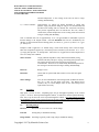
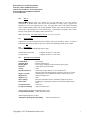
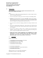
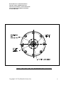
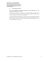
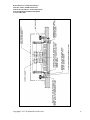
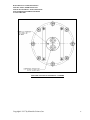
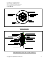
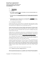
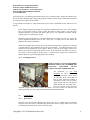
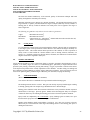
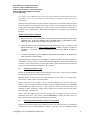
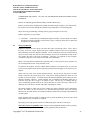
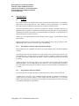
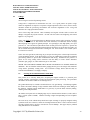
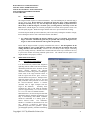
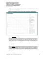
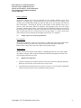
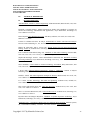
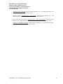
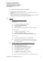
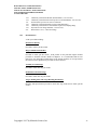
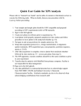
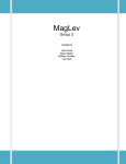
DOCUMENT NO. 251070, REV. E INSTALLATION, OPERATION AND USE OF SUNSOUCE ROUND PLANAR MAGNETRON CATHODES 22 JANUARY 2009 Materials Science, Inc. 1662 Los Altos Road San Diego, CA 92109 www.msi-pse.com Copyright© 1997 by Materials Science, Inc. DOCUMENT NO. 251070, REVISON E INSTALLATION, OPERATION AND USE OF SUNSOURCE™ ROUND PLANAR MAGNETRON SPUTTERING SOURCES 22 JANUARY 2009 TABLE OF CONTENTS Page No. 1.0 OVERVIEW 1 2.0 SPECIFICATIONS 2.1 Selecting The Correct Target Mounting Method 2.2 Target Thickness 2.3 Magnetic Field Strength 2.4 Pressure Range 2.5 Ultimate Pressure 2.6 Bakeout Temperature 2.7 Cooling Water 2.8 Argon Gas 2.9 Mounting Flanges 2.10 Power 2.11 Tapped Holes 2.12 Gas Fittings 2.13 Materials of Construction 1 4 4 5 5 5 5 6 6 7 7 7 7 INSTALLATION 3.1 Tools Required 8 8 3.2 Internal Sputtering Sources 3.2.1 Connecting Utilities Water / Water Lines Power Sputtering Gas 3.2.2 Feedthrough Arrangements 9 9 10 10 11 14 3.3 External Sputtering Sources 15 3.4 Flange Mount Sputtering Sources 3.4.1 Connecting Utilities Water / Water Lines Power Sputtering Gas 18 18 18 18 19 3.5 Electrical Power 3.5.1 RF Power 3.5.1.1 Matching Network Installation 3.5.1.2 Simultaneous Operation of Multiple RF Sources 3.5.2 DC Power 3.5.3 Grounding Practices 21 21 21 21 22 23 3.6 Cooling Water 3.6.1 Water Lines 3.6.2 Pressure Regulation 3.6.3 Water Quality 23 23 24 24 3.7 Sputtering Gas 24 3.0 Copyright© 1997 by Materials Science, Inc. i DOCUMENT NO. 251070, REVISON E INSTALLATION, OPERATION AND USE OF SUNSOURCE™ ROUND PLANAR MAGNETRON SPUTTERING SOURCES 22 JANUARY 2009 Page No 3.8 4.0 5.0 6.0 8.0 9.0 25 25 25 25 25 OPERATION 25 4.1 4.2 4.3 25 26 26 Pressure Range Power Density Cooling Water TARGET MATERIALS 26 5.1 5.2 5.3 5.4 26 27 28 28 Target Bonding Exchanging Clamped Targets Exchanging Bonded and Directly Water Cooled Targets Target Conditioning MAINTENANCE 29 6.1 29 29 29 30 30 31 6.2 6.3 6.4 7.0 Interlocks 3.8.1 Electrical 3.8.2 Water 3.8.3 Vacuum 3.8.4 Gas Insulators 6.1.1 Bolt Insulators 6.1.2 Body Insulator (External Cathodes) O-rings Cleaning the Ground Shield and Cathode Body Magnet Module PERFORMANCE ISSUES 31 7.1 7.2 7.3 7.4 7.5 31 32 32 33 33 Film Thickness Distribution Backscattering Pumping Unique Aspects of Certain Target Materials High Pressure Operation TECHNICAL REFERENCES 34 8.1 34 Recommended Reading TROUBLESHOOTING 36 9.1 9.2 9.3 9.4 9.5 9.6 36 36 36 36 36 37 Target Overheating Plasma Will Not Ignite Weak Discharge - Low Deposition Rate Plasma Extinguishes or is Intermittent Milky Films Galvanic Corrosion of Parts Exposed to Cooling Water Copyright© 1997 by Materials Science, Inc. ii DOCUMENT NO. 251070, REVISON E INSTALLATION, OPERATION AND USE OF SUNSOURCE™ ROUND PLANAR MAGNETRON SPUTTERING SOURCES 22 JANUARY 2009 10.0 APPENDIX 37 10.1 10.2 10.3 37 37 38 Installation Parts Included With New Sputter Source Spare Parts Included With New Sputter Source Documentation Copyright© 1997 by Materials Science, Inc. iii DOCUMENT NO. 251070, REVISON E INSTALLATION, OPERATION AND USE OF SUNSOURCE™ ROUND PLANAR MAGNETRON SPUTTERING SOURCES 22 JANUARY 2009 1.0 OVERVIEW SunSource sputtering sources can be configured to meet specific processing requirements; consequently, some features of individual sputtering sources may be different than what is described in this manual. Examples of these variations include special mounting arrangements, magnet modules with unique field shapes and intensities, and completely custom designs. Consequently, certain features (such as operating pressure range and maximum target thickness, for example) may vary from the values specified in this manual. However, basic utility and maintenance requirements will remain valid. It is assumed that the user of these sputtering sources is familiar with the requirements of magnetron sputtering. Issues such as ensuring proper gas flow across the target surface, the need for a properly designed vacuum pumping system, design and installation of user supplied ground shields and other basic items which affect the performance of the magnetron sputtering source which are not addressed in this manual. There are a number of good texts which address many of the processing issues relevant to magnetron sputtering. Some of these are identified in Section 7.0 Technical References. Please visit our web site: www.msi-pse.com to obtain drawings, specifications, manuals, spare parts and other information required to install, maintain and use SunSource Sputtering Sources. TEL/FAX: (858) 483-3223 E MAIL: [email protected] 2.0 SPECIFICATIONS 2.1 Selecting the Correct Target Thickness and Mounting Method The standard magnet modules supplied with SunSource sputtering sources have been optimized to maximize target utilization for non-magnetic materials within a certain thickness range as illustrated in the finite element analysis model. Although it’s not strictly true, it fair to say for the purposes of this manual that the region of material removal generally mirrors the shape of the magnetic field lines. Use of targets which are significantly thicker or thinner results in worse target utilization, narrower operating pressure range, distribution profiles which vary significantly from predicted results and degraded performance. Why? The electrons which create the plasma discharge are accelerated toward the target at a 90° angle relative to the magnetic field lines. Therefore, when the field lines are “flat” across the target surface it is uniformly eroded. The steeper the angle is at the target surface, the more “pinched” the erosion groove will be. Using targets which are too thick creates this condition. The area of target material removal does not increase as the target erodes. Once the erosion profile has been established on the target surface, it will remain constant throughout the life of the target. Another significant drawback to using targets which are too thick is that this promotes areas of material redeposition and insulating film growth (since very weak or no plasma discharge is present where the target is not being eroded) to prevent this situation from occurring. Copyright© 1997 by Materials Science, Inc. 1 DOCUMENT NO. 251070, REVISON E INSTALLATION, OPERATION AND USE OF SUNSOURCE™ ROUND PLANAR MAGNETRON SPUTTERING SOURCES 22 JANUARY 2009 RADIAL TARGET SECTION WITH MAGNETIC FIELD LINES SUPERIMPOSED TO ILLUSTRATE IMPORTANCE OF USING CORRECT TARGET THICKNESS Clamped Targets It’s certainly possible to clamp a target to the backing plate provided with the cathode and commence sputtering. No target bonding expense is incurred and the target cannot burn through and spring a water leak. However, this arrangement should used only in limited instances because it is thermally very inefficient (three point contact radiant heat transfer- between the target and backing plate in the center) resulting in poor thermal transfer. Targets can crack, warp, overheat, and form insulating regions among other problems. Low rates of deposition can be expected due to target overheating. Clamped targets can be used when depositing relatively thin films at low power levels. When depositing such thin films thermal problems are irrelevant because the target never gets hot enough to matter. Copyright© 1997 by Materials Science, Inc. 2 DOCUMENT NO. 251070, REVISON E INSTALLATION, OPERATION AND USE OF SUNSOURCE™ ROUND PLANAR MAGNETRON SPUTTERING SOURCES 22 JANUARY 2009 Bonded Targets Required when using multi-piece, poor thermal conductivity materials or targets having poor structural strength. ZnO, I-T-O, doped Si, C and similar targets should be bonded to the backing plate to minimize insulating film and “whisker” growth caused by hot spots (poor thermal conductivity The target clamp performs the function of compressing the o-ring and filling the space between the target and backing plate O.D., thus preventing a glow discharge in the region. Directly Water Cooled Targets Recommended when materials with high structural strength are used and very high power levels are applied or the user simply wishes to eliminate the cost of target bonding. Usually a step is machined on the top edge of the target so that target material which is sputtered at low angles is not collected on the lip of the target clamp (maintenance and process implications), although this is not strictly necessary. High power, high rate reactive TiN films should be grown using directly water cooled (no backing plate) thick Ti targets. Copyright© 1997 by Materials Science, Inc. 3 DOCUMENT NO. 251070, REVISON E INSTALLATION, OPERATION AND USE OF SUNSOURCE™ ROUND PLANAR MAGNETRON SPUTTERING SOURCES 22 JANUARY 2009 2.2 Target Thickness Low Permeability Materials Sputtering sources are supplied with one backing plate which ranges from 0.125” to 0.25” thick, depending upon the application the cathode was ordered for. A target clamping ring appropriate to the target mounting method is also supplied. Optimal performance (widest pressure range, best target utilization and the most stable process conditions) is achieved when a combined backing plate/target thickness of 0.50 ” to 0.625” is used. High Permeability Materials A magnet module specifically designed for the magnetic material being sputtered must be supplied. Contact the factory for assistance. 2.3 Magnetic Field Strength (Typical Values) Field profiles for the magnet module(s) provided with the sputtering source(s) purchased are included in the Documentation CD. It’s a good idea, if possible, to measure the magnet module field strength at the center and edge (both horizontal and vertical fields) on receipt before the cathode is used. Log the values recorded on the appropriate field profiles in the Appendix for future reference. The magnetic field should be uniform within +/- 5% between any two points on the same diameter within the erosion area. Materials Science, Inc. uses a Lake Shore Cryotronics Model 460 3 channel gaussmeter calibrated and traceable to NIST (National Institute of Standards and Technology) reference standards. Measured values are sensitive to the probe design plus the orientation and positioning of the probe when taking measurements. It’s possible for two different individuals using different gaussmeters and probes to record values that vary by several hundred gauss for the same magnet module. Profiling the field strength (and establishing a known baseline using your own instrument) of the magnet module on receipt eliminates any potential confusion caused by this difference when attempting to diagnose potential degradation of magnet modules. Suspected degradation in the magnet module should then be compared against these recorded values. It is important that a uniform magnetic field is maintained throughout the target racetrack area. Significant variations between any two points on the same radius can cause the target to be eroded at a faster rate in the areas of higher field strength, resulting in poor target utilization and nonuniform films. Damage to the magnet assembly is the only reason this problem will occur. Overheating of the magnet module is almost always the reason for degraded magnet module performance. Dropping the magnet module can also cause shifts in or loss of field strength. Copyright© 1997 by Materials Science, Inc. 4 DOCUMENT NO. 251070, REVISON E INSTALLATION, OPERATION AND USE OF SUNSOURCE™ ROUND PLANAR MAGNETRON SPUTTERING SOURCES 22 JANUARY 2009 2.4 Pressure Range High End: Approximately 1 Torr (Efficient magnetron sputtering occurs at pressures of 3 x 10⁻² Torr argon pressure or less). Low End: A plasma can be ignited and sputtering sustained at pressures of approximately 5 x 10⁻⁴ Torr argon pressure using any combination of target and backing plate thickness up to 0.625” thick for non-magnetic targets. Stable operation is dependent upon having a pumping system with sufficient gas throughput capacity and mass flow controllers and throttle valves capable of operating in the desired region. 2.5 Ultimate Pressure A base pressure of 5 x 10⁻⁹ Torr can be achieved in a well constructed and maintained vacuum system with sputtering sources installed. All parts and surfaces exposed to vacuum and process gas have been electropolished or precision chemically cleaned for UHV compatability. 2.6 Bakeout Temperature With cooling water flowing: 20o to 180o C No cooling water flowing: 20o to 50o C (limited only by ability to keep cathode cool) ⇒ Note: Ion sources, heaters, filaments and other devices can cause significant heating of the sputtering source even while it is turned off. It’s a good practice to leave the cooling water running at all times the chamber is under vacuum and in use to protect against inadvertent overheating of the magnet module and temperature sensitive parts. 2.7 Cooling Water Water Circuit: When using multiple sources, always connect them in parallel, NOT in series. Connecting sources in series causes increasing backpressure in the cooling water circuit, inadequate flow and inlet temperatures in the succeeding sources that are too high, resulting in premature magnet module failure due to overheating. Inlet temperature: Room temperature recommended. The temperature of chilled water systems should be regulated so that the dewpoint is never reached. Exit temperature: 50 degrees C maximum Flow: 4” and 5” Cathodes: Approximately 2 gallons per minute maximum @ 30psig inlet pressure, 0 psig exit pressure using 60” long, 0.375” ID water lines and specified water fittings with no internal flow restrictions. Increasing inlet pressure significantly does not increase the flow rate, which is constricted by internal backpressure in the cooling circuit. Increasing inlet pressure significantly does not increase the flow rate, which is constricted by Copyright© 1997 by Materials Science, Inc. 5 DOCUMENT NO. 251070, REVISON E INSTALLATION, OPERATION AND USE OF SUNSOURCE™ ROUND PLANAR MAGNETRON SPUTTERING SOURCES 22 JANUARY 2009 internal backpressure in the cooling circuit and can lead to target cracking and debonding. 6”, 7” and 8” Cathodes: Approximately 3-5 gallons per minute maximum @ 30psig inlet pressure, 0 psig exit pressure using 60” long, 0.375” ID water lines and specified water fittings with no internal flow restrictions. Increasing inlet pressure significantly does not increase the flow rate, which is constricted by internal backpressure in the cooling circuit and can lead to target cracking and debonding. Note: A minimum flow rate of approximately 1.0 to 1.50 gpm should be established to prevent thermal damage to the magnet module. Practical maximum flow rates are established by the ductility of target materials and/or backing plates (see below). A good rule of thumb: use 2 gpm per 5KW power. Example: 8 KW is applied to a 6” cathode using a 0.625” thick directly water cooled Al target. Inlet water temperature supplied by a closed-loop water recirculator cycles between 14° C - 21°C @ 30 psig inlet pressure - no back pressure. Water flow is 4.75 gpm and exit water temperature is 26°C in a steady state condition. Water Pressure: 30 psig (material dependent - many metals and structurally strong materials can safely take up to 70 psig). Increasing water pressure does not result in increased water flow beyond 30 psig and is not recommended. The flow rate is constricted by internal backpressure in the cooling circuit and can lead to target cracking and debonding. PH Level: Range of 6 to 8 Resistance: Greater than or equal to 50K ohms (relative to true earth, not signal ground) Water Fittings: Two (2) each P/N 00000168 water fittings (made by Materials Science, Inc.) for ½” OD, 3/8” ID plastic water lines. The Delrin sleeves (ferrules) may be reused multiple times on the same tubing before replacement is necessary. 2.8 Argon Gas High purity (at least 99.995). Depending upon the gas throughput capability of the vacuum system, 5-10 sccm, when injected through the cathode, is sufficient to sustain a plasma discharge. Flow rates of up to 200 sccm can be injected through the cathode. Flow rates which exceed the gas throughput capacity of the system can raise the pressure within the dark space region too high, resulting in arcing and sputtering of the cathode and ground shield. 2.9 Mounting Flanges Internal: KF 40, KF 50, 2.75” and 3.375” OD CF flange External: O-Ring Seal per installation drawing. Flange Mount: ISO Flange (typically) with O-ring seal per installation drawing. Copyright© 1997 by Materials Science, Inc. 6 DOCUMENT NO. 251070, REVISON E INSTALLATION, OPERATION AND USE OF SUNSOURCE™ ROUND PLANAR MAGNETRON SPUTTERING SOURCES 22 JANUARY 2009 2.10 Power SunSource sputtering sources are suitable for use with either RF or DC power without modification. A Multi-Contact USA P/N 05.0201 SP6AR-N/10 locking plug is supplied for integration into the user supplied power cable. The plug mates with a P/N 00000712 locking socket (modified Multi-Contact P/N 01.0200 B6ARNS locking socket with the threads cut short) screwed into a M6 threaded hole on the cathode body. Some models are supplied with a socket head cap screw instead of the Multi-Contact connector set. Multi-Contact USA: www.multi-contact-usa.com. Tel: (707) 575-7575. 2.11 Tapped Holes Tapped holes are fitted with helicoil inserts and those exposed to vacuum are vented. An insert is intentionally not fitted provided for the power connection to maintain good RF power contact. 2.12 Gas Fittings (Internal & Flange Mount Sputtering Sources Only) Cathode Body Gas Fitting: Gas Line Union: 2.13 Swagelok SS-200-6 1/8” OD Tube Swagelok SS-200-6 1/8” OD Tube Materials of Construction Cathode Body Clamping Ring Backing Plate Insulators O-rings Threaded Fasteners Magnet Assembly Magnet Plate Magnet Cover Water Fittings Water Lines Gas Injection Line Gas Injection Fittings - C110 Copper - AISI 304 stainless steel - C110 Copper (standard) or other materials upon request - Virgin Electrical Grade Teflon - Viton - Chemically cleaned AISI 316 or 18-8 stainless steel. Fasteners used in blind tapped holes exposed to vacuum are vented. - NdFeB magnet array encapsulated in dense, durable epoxy resin - AISI 416 stainless steel - Brass - Brass and AISI stainless steel, with Delrin compression sleeves - Polyethylene or appropriate plastic (lines must have high dielectric value) - Teflon PFA - AISI 316 stainless steel (Internal and Flange Mount Sputtering Sources Only) Ground Shield Assembly - AISI 304 stainless steel (Internal Sputtering Sources Only) Atmospheric Housing/Mounting Flange Copyright© 1997 by Materials Science, Inc. - AISI 304 stainless steel 7 DOCUMENT NO. 251070, REVISON E INSTALLATION, OPERATION AND USE OF SUNSOURCE™ ROUND PLANAR MAGNETRON SPUTTERING SOURCES 22 JANUARY 2009 3.0 INSTALLATION Refer to the Installation Control Drawing supplied with the documentation CD. This drawing is also available on our web site. Notes: • Backing plates are shipped with the bonding/clamping surface toward the magnet module to protect it from damage during shipment. • Always use either powder free plastic gloves or lint free cloth gloves when handling cathode. ⇒ NEVER lubricate threaded hardware as the lubricant inevitably is deposited on the substrate. Throw away fasteners and use new ones each time. The native oxide on the threads which prevents galling is broken when a new threaded connection is made. Reused fasteners almost always seize and gall, often resulting in expensive repairs and rework. • Always leak check the cathode after shipping, installation and exchange of bonded or solid targets. • Take care not to damage polished sealing surfaces. Minor scratches may be buffed out using Scotchbrite or fine-grit emory paper, but deep gouges and scratches usually require the surface to be re-machined. • Always check the cathode for resistance relative to chamber and true earth ground after installation. Resistance should be equal to or greater than 50K ohms with cooling water present. An open circuit should be indicated when water is absent. ⇒ NEVER USE METAL TUBING BETWEEN THE SPUTTERING GAS INLET CONNECTION ON THE CATHODE BODY AND THE TUBING UNION PROVIDED!!!! THE TEFLON PFA TUBING PROVIDED HAS AN EXTREMELY HIGH DIELECTRIC VALUE AND IS USED AS AN INSULATOR. 3.1 Tools Required Digital or Analog Multimeter 5 /16” Open End Wrench for Argon Gas Fitting on Cathode Body /16” Open End Wrench for 2.75” OD CF Flange ½” Open End Wrench for 3.375” OD CF Flange 11 /16” Open End Wrench for Water Fittings ¾” Open End Wrench for Water Fitting Nuts 7 7 /64” /32” 9 /64” 3 /16” 5 Hex Wrench for Ground Shields Hex Wrench for Bulkhead KF-50 Flange and Bolt Insulators Hex Wrench for Target Clamp Hex Wrench for Power Connection Phillips Screwdriver for 0.125” Thick Target Clamping Rings Wide Blade Flat Screwdriver for Bolt Insulator End Caps Copyright© 1997 by Materials Science, Inc. 8 DOCUMENT NO. 251070, REVISON E INSTALLATION, OPERATION AND USE OF SUNSOURCE™ ROUND PLANAR MAGNETRON SPUTTERING SOURCES 22 JANUARY 2009 3.2 Internal Sputtering Sources 3.2.1 Connecting Utilities Refer to the Installation Control Drawing supplied with the documentation CD. This drawing is also available on our web site. Internal sputtering sources usually have a KF or CF vacuum fitting machined into the mounting flange. This mounting flange must first be removed to make the water, power and gas connections at the cathode body, per the following procedure: • • • • • • • • • • Remove the three (3) side ground shield fasteners. Unscrew the bolt insulator end caps. Loosen the socket head cap screws within the bolt insulators in an alternating pattern to gradually relieve the tension. When the screws are completely disengaged, try to remove each bolt insulator with the socket head cap screw and washer stack as an assembly for ease of reassembly. Lift the mounting flange from the cathode body. Set the insulator and o-rings aside, being careful not to gouge or damage the sealing surfaces. Make the water, power and gas connections as noted below. Draw the power, water and argon gas lines through the ID of the insulator, then the mating flange. Reposition the insulator within the step of the mounting flange. Assemble in reverse order of initial disassembly. (If the screw and washers have been removed from the bolt insulator during disassembly, make sure that the washer stack is reassembled with the smallest diameter washer closest to the screw head and the largest against the bolt insulator to ensure uniform loading and maintain the necessary spring action.) Copyright© 1997 by Materials Science, Inc. 9 DOCUMENT NO. 251070, REVISON E INSTALLATION, OPERATION AND USE OF SUNSOURCE™ ROUND PLANAR MAGNETRON SPUTTERING SOURCES 22 JANUARY 2009 Water/Water Lines Lightly grease the o-ring, finger tighten, then use a wrench on the hex flat to turn approximately another ¼ turn, making the seal water tight. Use at least a 60” (153mm) length of ½” OD) polyethylene (McMaster-Carr P/N 5181K26) or other suitable plastic tubing for each water line. Make sure that both ends of each tube have been cut flush. Insert tube end until it bottoms out against the fitting, then turn the hex nut finger tight. Use a wrench to make about 1 ½ complete turns after finger tightening to ensure the delrin compression sleeve is completely engaged. The water line should not pull out of the fitting when tugged on. ⇒ DO NOT PRESS TUBE INSERTS INTO THE ID OF THE WATER LINES PRIOR TO INSERTING THE WATER LINES INTO THE COMPRESSION FITTINGS. THE INSERTS SIGNIFICANTLY RESTRICT WATER FLOW AND ARE NOT NECESSARY TO KEEP THE TUBING RIGID WHEN THE SPECIFIED DELRIN COMPRESSION SLEEVES ARE USED. ⇒ ALWAYS CONNECT MULTIPLE SOURCES IN PARALLEL, NEVER IN SERIES. Refer to comments in Section 2.7 Cooling Water. Power Connect the cable to the cathode body using the locking socket connector set or socket head cap screw provided. See Section 3.5 Electrical Power. Copyright© 1997 by Materials Science, Inc. 10 DOCUMENT NO. 251070, REVISON E INSTALLATION, OPERATION AND USE OF SUNSOURCE™ ROUND PLANAR MAGNETRON SPUTTERING SOURCES 22 JANUARY 2009 Sputtering Gas The gas fitting has an o-ring face seal. Attach the fitting to the port marked “G” and finger tighten the fitting until metal to metal contact is made. The tubing connection is made using a Swagelok SS-200-6 1/8” OD tube fitting. Use 1/8” OD tubing to connect between the Swagelok gas fitting on the cathode body and the Swagelok union. Attach the union after the gas line has been fed through the feedthrough assembly. Alternatively, a gas line long enough to connect directly to the metering valve or mass flow controller may be used, eliminating the need for the union. Notes: • Tubing that is oval, that will not easily fit through the fitting nuts, ferrules and bodies should not be used. • Surface finish is very important to proper sealing. Tubing with any kind of depression, scratch, raised portion or other surface defect will be difficult to seal. • Insert tubing into Swagelok gas fitting. Make sure that the tubing face has been cut flat and smooth (not diagonally across the tube or ragged) so that the tubing face rests firmly on the shoulder of the fitting and that the nut is finger-tight. Tightening Instructions: • Never turn fitting body, Instead hold fitting body and turn nut. • Hold the fitting body steady using the wrench flat on the fitting body and tighten the nut 1¼ turns. The gas connection can be disconnected and reused many times. To retighten: • Insert tubing with pre-swaged ferrules into fitting body until the front ferrule is fully seated. • Tighten nut by hand, then rotate nut to the original position with a wrench as noted above. An increase in resistance will be encountered at the original position. Tighten very slightly beyond this point. Copyright© 1997 by Materials Science, Inc. CORRECT ORIENTATION OF FRONT AND BACK FERRULES 11 DOCUMENT NO. 251070, REVISON E INSTALLATION, OPERATION AND USE OF SUNSOURCE™ ROUND PLANAR MAGNETRON SPUTTERING SOURCES 22 JANUARY 2009 SIDE VIEW OF UTILITY AND VACUUM FEEDTHROUGH CONNECTIONS Copyright© 1997 by Materials Science, Inc. 12 DOCUMENT NO. 251070, REVISON E INSTALLATION, OPERATION AND USE OF SUNSOURCE™ ROUND PLANAR MAGNETRON SPUTTERING SOURCES 22 JANUARY 2009 UTILITY , MOUNTING AND VACUUM FEEDTHROUGH CONNECTIONS Copyright© 1997 by Materials Science, Inc. 13 DOCUMENT NO. 251070, REVISON E INSTALLATION, OPERATION AND USE OF SUNSOURCE™ ROUND PLANAR MAGNETRON SPUTTERING SOURCES 22 JANUARY 2009 3.2.2 Feedthroughs A variety of feedthrough arrangements using industry standard fittings and flanges can be used to install internal mount cathodes into the vacuum chamber. An X-Y-Z positioning feedthrough offered by Materials Science, Inc. is shown to illustrate the possibilities. Contact factory for assistance. Copyright© 1997 by Materials Science, Inc. 14 DOCUMENT NO. 251070, REVISON E INSTALLATION, OPERATION AND USE OF SUNSOURCE™ ROUND PLANAR MAGNETRON SPUTTERING SOURCES 22 JANUARY 2009 3.3 External Sputtering Sources Refer to the Installation Control Drawing supplied with the documentation CD. drawing is also available on our web site. This A polished o-ring sealing surface (32 RMS) must be provided surrounding the cathode cutout in the vacuum chamber. The cathode must be firmly and uniformly clamped to the chamber wall to ensure leak free pump down of the system from atmosphere. The installation arrangement should include a method of precisely repositioning the cathode and ground shield after they have been removed to maintain specified, uniform dark space gap. Failure to do so will likely result in arcing, pitting of the cathode body and ground shield, as well as coating of and damage to the insulator. Copyright© 1997 by Materials Science, Inc. 15 DOCUMENT NO. 251070, REVISON E INSTALLATION, OPERATION AND USE OF SUNSOURCE™ ROUND PLANAR MAGNETRON SPUTTERING SOURCES 22 JANUARY 2009 Copyright© 1997 by Materials Science, Inc. 16 DOCUMENT NO. 251070, REVISON E INSTALLATION, OPERATION AND USE OF SUNSOURCE™ ROUND PLANAR MAGNETRON SPUTTERING SOURCES 22 JANUARY 2009 TOP VIEW OF TYPICAL EXTERNAL CATHODE Copyright© 1997 by Materials Science, Inc. 17 DOCUMENT NO. 251070, REVISON E INSTALLATION, OPERATION AND USE OF SUNSOURCE™ ROUND PLANAR MAGNETRON SPUTTERING SOURCES 22 JANUARY 2009 3.4 Flange Mount Sputtering Sources 3.4.1 Connecting Utilities Refer to the Installation Control Drawing supplied with the documentation CD. This drawing is also available on our web site. Flange mount sputtering sources have a bulkhead KF-50 bolt pattern machined into the mounting flange. A black Delrin protective cap must first be removed to make the water, power and gas connections at the cathode body. The cap positively locates in a step within the bulkhead pattern. Feed the water, power and gas lines through the slotted holes in the protective cap before using the bulkhead clamps to fasten the protective cap in place Water/Water Lines Lightly grease the o-ring, finger tighten, then use a wrench on the hex flat to turn approximately another ¼ turn, making the seal water tight. Use at least a 60” (153mm) length of ½” OD) polyethylene or other suitable plastic tubing for each water line. Make sure that both ends of each tube have been cut flush. Insert tube end until it bottoms out against the fitting, then turn the hex nut finger tight. Use a wrench to make about 1 ½ complete turns after finger tightening to ensure the delrin compression sleeve is completely engaged. The water line should not pull out of the fitting when tugged on. ⇒ DO NOT PRESS TUBE INSERTS INTO THE ID OF THE WATER LINES PRIOR TO INSERTING THE WATER LINES INTO THE COMPRESSION FITTINGS. THE INSERTS SIGNIFICANTLY RESTRICT WATER FLOW AND ARE NOT NECESSARY TO KEEP THE TUBING RIGID WHEN THE SPECIFIED DELRIN COMPRESSION SLEEVES ARE USED. ⇒ ALWAYS CONNECT MULTIPLE SOURCES IN PARALLEL, NEVER IN SERIES. Refer to comments in Section 2.7 Cooling Water. Power Connect the cable to the cathode body using the locking socket connector set or socket head cap screw provided. See Section 3.5 Electrical Power. Copyright© 1997 by Materials Science, Inc. 18 DOCUMENT NO. 251070, REVISON E INSTALLATION, OPERATION AND USE OF SUNSOURCE™ ROUND PLANAR MAGNETRON SPUTTERING SOURCES 22 JANUARY 2009 Sputtering Gas The gas fitting has an o-ring face seal. Attach the fitting to the port marked “G” and finger tighten the fitting until metal to metal contact is made. The tubing connection is made using a Swagelok SS-200-6 1/8” OD tube fitting. Use 1/8” OD tubing to connect between the Swagelok gas fitting on the cathode body and the Swagelok union. Attach the union after the gas line has been fed through the feedthrough assembly. Alternatively, a gas line long enough to connect directly to the metering valve or mass flow controller may be used, eliminating the need for the union. Notes: • Tubing that is oval, that will not easily fit through the fitting nuts, ferrules and bodies should not be used. • Surface finish is very important to proper sealing. Tubing with any kind of depression, scratch, raised portion or other surface defect will be difficult to seal. • Insert tubing into Swagelok gas fitting. Make sure that the tubing face has been cut flat and smooth (not diagonally across the tube or ragged) so that the tubing face rests firmly on the shoulder of the fitting and that the nut is finger-tight. Tightening Instructions: • Never turn fitting body, Instead hold fitting body and turn nut. • Hold the fitting body steady using the wrench flat on the fitting body and tighten the nut 1¼ turns. The gas connection can be disconnected and reused many times. To retighten: • Insert tubing with pre-swaged ferrules into fitting body until the front ferrule is fully seated. • Tighten nut by hand, then rotate nut to the original position with a wrench as noted above. An increase in resistance will be encountered at the original position. Tighten very slightly beyond this point. Copyright© 1997 by Materials Science, Inc. CORRECT ORIENTATION OF FRONT AND BACK FERRULES 19 DOCUMENT NO. 251070, REVISON E INSTALLATION, OPERATION AND USE OF SUNSOURCE™ ROUND PLANAR MAGNETRON SPUTTERING SOURCES 22 JANUARY 2009 UTILITY CONNECTIONS SIDE VIEW SHOWING UTILITY AND VACUUM CONNECTIONS Copyright© 1997 by Materials Science, Inc. 20 DOCUMENT NO. 251070, REVISON E INSTALLATION, OPERATION AND USE OF SUNSOURCE™ ROUND PLANAR MAGNETRON SPUTTERING SOURCES 22 JANUARY 2009 3.5 3.5.1 Electrical Power RF Power ⇒ RF POWER SUPPLIES MUST BE COUPLED TO THE CATHODE THROUGH A MATCHING NETWORK. ⇒ Note: RF power connections should only be made by persons familiar with and fully qualified to perform such work. RF POWER LEAKAGE CAN CAUSE SERIOUS INJURY OR DEATH. ⇒ External sputtering sources should be fully covered and shielded by a user supplied protective, INTERLOCKED enclosure. Radiated power levels should be checked by qualified personnel prior to routine operation of the system. 3.5.1.1 Matching Network Installation The RF power supply may be remotely located. Use only properly rated coaxial cable to connect the power supply to the matching network. Do not coil the cable. An M6 tapped hole is provided for connection of the user supplied power cable or hard plumbed connection. Flexible coaxial cables are prone to serious overheating. When making your own cables, keep the distance between the matching network and the cathode as short as possible (recommend no longer than 3 feet), exercise extreme caution and consult an RF power expert. The impedance can create large circulating currents on this interconnect cable. Any increase in circulating current greatly increases the losses in the cable. In light of this fact, a Teflon dielectric cable (RG 393 is recommended) should be used because Teflon has more favorable thermal characteristics than other cable materials. The Teflon will minimize migration of the center conductor due to overheating, thus reducing the probability of the center conductor shorting to the outer sheath. Better still - make a hard plumbed connection. A key consideration in the placement of the matching network is the return current from the matching network/chamber system. If an RF cable is used to connect the tuner to the chamber, all the circulating return currents will be on the outer sheath of the cable. Good ground connections which meet local electrical codes are essential. The matching network should be grounded (usually through its AC power connector). Additionally, the matching network should have a good RF ground. Good RF grounding is aided by mounting the matching network as close as possible to the vacuum feedthrough. Improper grounding of the matching network will result in radio frequency interference (RFI). RFI causes instrumentation and computers to operate erratically, solenoid controlled devices such as valves to “chatter” and other problems. Ground planes within the chamber must be kept equidistant from the cathode. 3.5.1.2 Simultaneous Operation of Multiple RF Sources When two or more RF power sources (i.e. two cathodes or one cathode with RF biased substrate) are run simultaneously, the phasing of the RF generators must be controlled. Slaving multiple RF Copyright© 1997 by Materials Science, Inc. 21 DOCUMENT NO. 251070, REVISON E INSTALLATION, OPERATION AND USE OF SUNSOURCE™ ROUND PLANAR MAGNETRON SPUTTERING SOURCES 22 JANUARY 2009 generators to the same crystal oscillator (“common oscillator”) allows the control of the phase relationship of the generators within the plasma. The phasing between generators is controlled through the use of a calibrated, variable line delay (“phase shifter”), usually sold as an optional device by most power supply manufacturers. Ensure that this device is included when power supplies are purchased. A matching network must be provided for each device connected to an RF generator. 3.5.2 DC Power ⇒ External cathodes should be fully covered and shielded by a user supplied protective, INTERLOCKED enclosure. A Multi-Contact USA P/N 05.0201 SP6AR-N/10 locking plug is supplied for integration into the user supplied power cable. The plug mates with a P/N 00000712 locking socket (modified Multi-Contact P/N 01.0200 B6ARNS locking socket with the threads cut short) screwed into a M6 threaded hole on the cathode body. The locking system operates on the “push-pull” principle. It is self-locking when connected. Disconnection is affected by an axially displaceable coupling ring: first push, then pull to disconnect. The plug cannot be pulled out of the socket unless this procedure is followed. SP6AR-N/10 Locking Plug P/N 00000712 Locking Socket MC - Locking System (AR system) Use a co-axial cable such as RG18 or RG213/U. Strip the outer sheath to expose the center conductor. Insert the exposed center power conductor into the plug cavity and fill the surrounding void with silver or other appropriate high temperature solder. Connect the outer sheath to a ground connection. Typically the outer sheath is soldered to an insulated solid copper wire run to the ground connection. Failure to establish a good ground will mean that electrons Copyright© 1997 by Materials Science, Inc. 22 DOCUMENT NO. 251070, REVISON E INSTALLATION, OPERATION AND USE OF SUNSOURCE™ ROUND PLANAR MAGNETRON SPUTTERING SOURCES 22 JANUARY 2009 that normally go to the cathode ground shield (anode) go to ground elsewhere (usually the chamber wall). This will result in unusually high voltage being required to run the cathode, which in turns limits the amount of power that can be applied to the cathode. A ring terminal held in place by a M6 socket head cap screw may be substituted for the connector set if so desired. Power supplies purposefully designed for magnetron sputtering should be used. These supplies have arc suppression circuitry, protect against RF transient voltage spikes (several KV) that magnetron plasmas can produce and allow output power to be regulated in constant voltage, constant current or constant power modes. The power supply should operate in a constant current mode in a range of at least 300 - 1000 volts. Typical magnetron sputtering occurs at 200 - 1000 volts. The surface area of the cathode will determine the current requirements. An RF filter should be put on the DC input to the chamber when RF bias is applied to the substrate or an RF cathode is used in addition to the DC powered cathode. 13.56 MHz will cause serious problems for most unfiltered DC power supplies. However, if the DC power supply is pulsed, care must be taken when selecting the RF filter to be used. If the inductance of the filter is too large, it may interfere with the pulsing of the DC supply. Consult the power supply user’s manual and a qualified RF power expert when applying this sort of biasing. 3.5.3 Grounding Practices VIEW OF TYPICAL VACUUM CHAMBER SHOWING TOP PLATE, CHAMBER AND FLANGE(S) GROUNDED (BLACK CABLES) TO TRUE EARTH GROUND The importance of true earth grounding for basic safety and equipment protection reasons cannot be overstated If the system does not have it, make certain this situation is immediately rectified. Do not confuse signal ground with true earth ground. Signal ground does not ensure safety. Users are referred to the referenced documents on this subject in 8.0 Technical Documents. For safety reasons, all conductive parts must be grounded to prevent voltage buildup and potentially lethal discharges. 3.6 Cooling Water 3.6.1 Water Lines Electrical power is transmitted through the cooling water circuit. Ensuring that the electrical resistivity of the water lines is sufficiently high prevents this from occurring. Refer to the section on cathode specifications for the correct resistivity values. Copyright© 1997 by Materials Science, Inc. 23 DOCUMENT NO. 251070, REVISON E INSTALLATION, OPERATION AND USE OF SUNSOURCE™ ROUND PLANAR MAGNETRON SPUTTERING SOURCES 22 JANUARY 2009 ⇒ Do not use water lines shorter than 60” (153 mm) for either the inlet and exit lines. Polyethylene water lines should be used. Use water lines with the maximum clear inner diameter to ensure proper water flow. Never use inserts at the ends of the water lines as they significantly restrict flow. Remember that the longer the water line, the greater the conductive loss (flow). NEVER use copper tubing or any metallic conductor. DO NOT USE THE WATER LINES AS THE POWER CONNECTION. Carbon filled (black) tubing is electrically conductive and must not be used. The inlet line should be located below the exhaust line on horizontally mounted sputtering sources. 3.6.2 Pressure Regulation Use a water flow regulator to control internal pressures within the cathode. It is generally recommended that the internal pressure does not exceed 30 psig when using brittle targets (though many metal targets can take up to 70 psig). Greater internal pressurization of the cathode causes the backing plate to warp and targets to crack, and water leakage past the backing plate o-ring seal can occur under extreme conditions (more than 100 psig). 3.6.3 Water Quality DO NOT use de-ionized or distilled water, as they will attack and corrode the copper body as well as the magnet plate. Conditioned city water in recirculating water systems is best. Anti-corrosion agents, such as ethylene glycol with additives (“Dowtherm”) should be used. Refer to the specification section for proper pH, temperature and other requirements. Avoid the use or algaecides or other water treatments. Galvanic corrosion will occur if materials other than brass, copper, elastomers, appropriate plastics and PTFE are present in the cooling water system. 3.7 Sputtering Gas Sputtering gas (typically argon or an argon gas mixture) is admitted through the cathode body and symmetrically distributed through the dark space region, allowing for uniform diffusion of the gas through the dark space gap and across the target surface. This feature is important, compared to simply introducing gas directly into the chamber or through a separate gas fitting or manifold, for several reasons: • • • • • • • Allows lower background pressures for higher purity films. Eliminates localized high pressure in one region of the target which results in premature burn-through of the target and disuniform film thickness on the substrate. Because no gas fittings, shields or manifolds are provided external to the cathode itself, the need for an additional feedthrough and gas lines within the vacuum chamber is eliminated. External gas fittings and injection shields usually are at ground potential and can glow red-hot. Target material is also deposited on these surfaces, causing process and maintenance problems. Much lower gas consumption compared to filling the entire chamber. Ensures that sputtering gas depletion on the target surface does not occur - an adequate supply of argon gas is always present to maintain desired sputtering rates. Allows the use of DC sputtering in the growth of reactively deposited films by maintaining a buffer region that mitigates against the formation of insulating films on the target surface when target material removal rates are also high enough. Copyright© 1997 by Materials Science, Inc. 24 DOCUMENT NO. 251070, REVISON E INSTALLATION, OPERATION AND USE OF SUNSOURCE™ ROUND PLANAR MAGNETRON SPUTTERING SOURCES 22 JANUARY 2009 3.8 Interlocks 3.8.1 Electrical External sputtering sources should always be covered by a protective enclosure equipped with magnetic breaks or microswitches that will immediately disable the cathode power supply when the cover is removed. The enclosure should be designed so that it must be properly installed and fully enclose and shield the cathode before the interlock is enabled to protect against careless installation. 3.8.2 Water Water flow sensors must be installed and interlocked to the power supply. This prevents damage to the cathode caused by inadequate or no cooling water flow. Overheating the magnet module will weaken or destroy the magnetic field very quickly! Flow meters and metering valves should be installed on the inlet side of the cathode. Flow sensors should be installed on the outlet side of the cathode. Switches which allow visual inspection and require positive water flow to induce a voltage and maintain relay closure are strongly suggested. Some water switches can fail closed and still indicate the presence of cooling water even when it is absent. ⇒ Each cathode should be provided with an independent water circuit as described above. Never provide cooling water to the cathodes in series. This practice reduces water flow, increases backpressure within the cooling circuit and could result in overheating of the cathodes. 3.8.3 Vacuum To further insure against process failures, a chamber vacuum gauge should be interlocked to the cathode power supply, which will prevent the power supply output from being turned on unless the chamber is within the required pressure range. 3.8.4 Gas The flow of sputtering gas may also be interlocked to the power supply when using mass flow controllers in order to maintain the sputtering environment within the desired range. 4.0 OPERATION 4.1 Pressure Range SunSource Sputtering Sources operate at pressures from approximately 1 Torr to 3 x 10⁻⁴ Torr argon pressure. 4.2 Power Density (Also see Section 5.0 Target Materials) Copyright© 1997 by Materials Science, Inc. 25 DOCUMENT NO. 251070, REVISON E INSTALLATION, OPERATION AND USE OF SUNSOURCE™ ROUND PLANAR MAGNETRON SPUTTERING SOURCES 22 JANUARY 2009 The better the thermal conductivity of the material, quality of fabrication technique and bond quality, the higher the maximum power density. Maximum allowable power densities are material dependent. The thermal characteristics of the target material, it’s sputter yield and whether the target is clamped (indirectly cooled), bonded to a backing plate or directly cooled all influence how much power can be applied to the target to achieve high rates. The following are guidelines only and are not to be taken as guarantees! Copper Most Metals Dielectrics 4.3 - Maximum 500 watts/in2 - Maximum 200 watts/in2. - Approximately 50 - 100 watts/in2. Alumina and SiO2 tend toward the low end, dense I-T-O toward the high end. Cooling Water It is important that cooling water be flowing through the cathode, with inlet and exit temperatures in the ranges given in the specifications section whenever the cathode and magnet assembly are subjected to heat. This would include normal operation of the cathode, as well as operation of nearby sources of heat within the vacuum chamber (such as heating elements, filaments, ion sources, etc.). Without cooling water flowing in these situations, the cathode will overheat and the magnetic field will be degraded or destroyed. 5.0 TARGET MATERIALS Target materials should be as close to theoretical density as possible, particularly when high purity work is required. Low density targets are sources of contaminating gases, particularly in targets fabricated from powders by hot pressing, vacuum hot pressing and sintering. Oxygen, in particular is sorbed on the surface of the unprocessed powder and is virtually impossible to later eliminate. Vacuum casting, arc-melting and hot isostatically pressing (HIPing) are usually superior fabrication techniques. Poor target density also can result in low sputtering rates, premature target exhaustion, poor utilization, warping and cracking. 5.1 TARGET BONDING (Refer to Materials Science, Inc. No. 10000000) Care must be taken not to contaminate the target material with the bonding agent. The bonding material must be void free. Hot spots can develop on poorly bonded targets resulting in melting, spitting and even complete target delamination due to thermal fatigue. Backing plates should be made from materials which most closely match the thermal expansion characteristics of the target. Specialty glasses, Sendust and certain magnetic alloys are examples of materials which may crack during the bonding process due to thermal expansion mismatch. Epoxy bonds are emphatically not recommended! Epoxy bonding agents are brittle, have poor thermal transfer properties and are sources of organic contamination. Metallic solder bonding, usually using indium, is preferred. Very often it is necessary to deposit adhesion layers on the backside of the target and bonding surface of the backing plate prior to making the solder bond. Copyright© 1997 by Materials Science, Inc. 26 DOCUMENT NO. 251070, REVISON E INSTALLATION, OPERATION AND USE OF SUNSOURCE™ ROUND PLANAR MAGNETRON SPUTTERING SOURCES 22 JANUARY 2009 Yes, we know it costs additional money to have the targets bonded, but clamped targets have three point contact in the center of the target and simply cannot be as efficiently cooled. Life is full of compromises! Dielectrics and certain metals and alloys which are brittle and/or poor thermal conductors should always be bonded to a backing plate and directly cooled to avoid cracking and warping. Direct cooling allows much higher applied power densities, hence at least two times the sputter rate of indirectly cooled, clamped targets. Brittle materials should never be clamped to avoid fracturing the target. WHEN EXCHANGING TARGETS ⇒ HIGH VOLTAGE CAN BE PRESENT EVEN WHEN POWER SUPPLIES HAVE BEEN TURNED OFF! ALWAYS GROUND THE CATHODE WITH A GROUNDING STICK PRIOR TO TOUCHING THE CATHODE FOR ANY REASON. ⇒ ALWAYS CHECK THE CATHODE BODY FOR RESISTANCE OF AT LEAST 50,000 OHMS RELATIVE TO A TRUE EARTH GROUND WHEN COOLING WATER IS FLOWING. AN OPEN CIRCUIT SHOULD BE INDICATED WHEN WATER IS ABSENT. ⇒ LET THE CATHODE COOL TO AMBIENT TEMPERATURE PRIOR TO TURNING OFF THE COOLING WATER SUPPLY. Target clamping bolts should not be over-tightened. Tighten the bolts in an alternating pattern to no more than 5 Newton-meters (44 Inch-pounds) maximum tightness. Set the torque rating of the wrench to a value of approximately one-half of this number, tighten all the bolts, then increase the setting several times until the recommended value is reached. 5.2 Exchanging Clamped Targets Remove the ground shield assembly (internal sputtering sources only). Remove the bolts holding the clamping ring in place and set clamping ring aside. DO NOT loosen or remove the screws which fasten the backing plate to the cathode body, otherwise the vacuum to water seal will be broken. Replace target and reverse procedure. Be sure that the clamping ring is correct for the target thickness. Do not use targets which are too thin to be firmly clamped and DO NOT USE SHIMS OR INSERTS TO TAKE UP SLACK. This results in extremely poor thermal contact and inadequate cooling. Furthermore, mating surfaces which are not vacuum relieved act like virtual leaks and outgas - causing arcing. Targets which are slightly thicker than the clamping ring is designed for may be used by substituting longer bolts. This practice is not recommended as a routine procedure, only as an interim measure until a properly sized clamping ring is obtained. 5.3 Exchanging Bonded and Directly Water Cooled Targets Drain the water from the cathode body and purge the water lines with nitrogen or dry, unlubricated compressed air prior to disassembling the cathode. DO NOT USE AN UNREGULATED Copyright© 1997 by Materials Science, Inc. 27 DOCUMENT NO. 251070, REVISON E INSTALLATION, OPERATION AND USE OF SUNSOURCE™ ROUND PLANAR MAGNETRON SPUTTERING SOURCES 22 JANUARY 2009 COMPRESSED AIR SUPPLY. DO NOT USE AIR PRESSURE WHICH EXCEEDS 20 PSIG MAXIMUM. Remove the adjustable ground shield assembly (internal cathodes only). Remove the bolts and/or clamping bars holding the bonded target assembly to the cathode body. Be careful not to scratch or damage the polished o-ring sealing surface on the backing plate. Inspect the o-ring for hardening, cracking, nicks or gouges and replace if necessary. Replace target and reverse procedure. ⇒ CAUTION: Avoid removing or handling the magnet assembly. Physical shock can weaken the magnet assembly and damage to the protective epoxy coating can allow water to attack and degrade the rare earth magnets. 5.4 Target Conditioning Magnetron cathodes are more likely to arc than other types of sputtering sources. This is due to the nature of the low voltage, high current power supplies required to drive the low impedance plasma discharge created by magnetron cathodes. An arc at full power caused by a small localized region of surface oxide can cause the entire discharge current to be momentarily focused on this spot, melting the target at the point of discharge. Therefore, it is important to first presputter (“condition”) targets to remove surface oxides and other contaminants. When a new target has been installed in a sputtering source, or the system has been exposed to air for extended periods of time, arcing will likely occur. To minimize this situation, close the cathode shutter, pump the system down below 10-4 Torr and let the pressure stabilize, then raise the sputtering system pressure and apply low level power to the cathode. Slowly increase power to the desired deposition density. Do not increase the power level until arcing is reduced at the present power level. This process should typically take about 30 to 60 seconds for most pure metals. A 5 minute ramp to the maximum allowable power density for other materials should be sufficient. Certain materials such as aluminum and titanium which form a tenacious oxide may take as long as 30 minutes to clean. The best way to establish what the correct conditioning period should be for various materials is to note how long it takes for the discharge current to fall to a constant value while controlling the voltage. The plasma should be stable and no arcing should occur upon completion of the conditioning period. The shutter can now be opened. It is assumed that targets which have been properly fabricated are used and that they are installed in cathodes situated in well designed and maintained vacuum systems. Target materials with poor density or which operate in poorly maintained systems may take much longer than this (up to 30 minutes) to condition. Increasing system argon pressure will aid in conditioning targets with heavy oxide layers. These time periods are guidelines only! Each user must establish the amount of time to properly condition targets empirically. There are no broadly applicable hard and fast rules. Copyright© 1997 by Materials Science, Inc. 28 DOCUMENT NO. 251070, REVISON E INSTALLATION, OPERATION AND USE OF SUNSOURCE™ ROUND PLANAR MAGNETRON SPUTTERING SOURCES 22 JANUARY 2009 6.0 MAINTENANCE 6.1 Insulators The cathode insulators are fabricated from virgin electrical grade Teflon because of it’s desirable characteristics such as high dielectric value, moderately low gas permeability, low outgassing rates, high operating temperature and good general resistance to chemical attack. The primary drawback to the use of Teflon is its propensity to cold flow, particularly when force is applied at higher temperatures. Insulators and o-rings may remain leak tight even after undergoing compression set until they are disturbed. Once disassembled, an insulator or o-ring that has taken a serious compression set cannot be reused. Teflon is also soft and susceptible to physical damage such as gouging. Always handle all Teflon parts carefully. Deposited material may be removed from the Teflon insulators using a fine grit abrasive cloth, dilute NaOH or HCl. Do not use solvents or grit or bead blasting. 6.1.1 Bolt Insulators (Internal and Flange Mount Cathodes) These insulators are an expendable item, but may be reused multiple times if cleaned and handled carefully. Gas scattering causes the bolt insulators to become quickly coated with the target material. The bolt insulators have a vented, protective cap which prevents a conductive coating from covering the inside of the insulator and shorting the cathode. Failure to install the protective cap will result in shorting Tighten the bolts in an alternating pattern to no more than 5 Newton-meters (44 Inch-pounds) maximum tightness. Set the torque rating of the wrench at a value of approximately one-half of this value, tighten all the bolts, then increase the setting several times until the recommended value is reached. 6.1.2 Body Insulator (External Cathodes) Viton o-ring seals are soft and don’t require much compression to obtain a good vacuum seal. A loading force of 1 kg/cm2 (15 psi - nominal atmospheric pressure) is sufficient to compress the o-ring(s) between the Teflon insulator, vacuum system wall and cathode body. As a practical matter, finger tightening the retaining bolts, then slightly tensioning them will make a leak tight seal without deforming the Teflon insulator. Copyright© 1997 by Materials Science, Inc. 29 DOCUMENT NO. 251070, REVISON E INSTALLATION, OPERATION AND USE OF SUNSOURCE™ ROUND PLANAR MAGNETRON SPUTTERING SOURCES 22 JANUARY 2009 6.2 O-Rings Viton o-rings are used in all sputtering sources. O-rings take a compression set and harden over time. It is a good practice to replace o-rings whenever degradation is suspected. Exposure to high temperature (above 150°C) and to various chemicals within the processing environment will accelerate degradation of the o-ring and determine the o-ring replacement schedule. Never clean o-rings with solvents. Most commonly used organic solvents such as acetone will damage or degrade the polymer material. All will enter the surface and outgassing will remain high for a very long time. Grease can usually be used without harm in unbaked vacuum systems where scratches in sealing surfaces, o-ring surfaces or dust would cause leaks otherwise, but Materials Science strongly discourages the use of grease on general principal. Use (sparingly!!!) only high quality, low vapor pressure (10-7 Torr and below) hydrocarbon based vacuum greases like Apiezon L, Apiezon M, Dow Corning DC 976 and equivalent products when the decision to use grease has been made. Do not use silicone based grease such as Dow Corning DC 704. Once silicone is in a vacuum system it can never be removed. Grease can cause gas bursts (and arcing) as gas escapes from the grease or from traps between the o-ring and mating surfaces, so the ideal practice is to use dry, unlubricated o-rings and to maintain good sealing surfaces to prevent film contamination and arcing. Furthermore, the presence of grease on an o-ring sealing surface interferes with the ability to locate surface anomalies (scratches, pits, gouges, etc.) that could cause gas or water leaks. NEVER USE ANYTHING HARDER THAN WOOD TO REMOVE AN O-RING FROM ITS GROOVE. The use of harder materials and/or gouging into the groove at an angle will scratch the o-ring surface, potentially causing leaks. P/N 53385A48 “Orange Sticks” (Birch wood) are available from McMaster-Carr Supply Company. 6.3 Cleaning the Ground Shield and Cathode Body Best practice is to send any metal parts (excepting the magnet module) to a precision parts cleaning company specializing in vacuum and semiconductor parts processing. The procedures noted below are for those unable or not wishing to do so. The ground shield may be cleaned as described below or by grit blasting. Grit blasting roughens the surface and reduces flaking of target material which could cause shorting or debris falling on the substrate. Regular periodic maintenance is a good way to prevent shorts caused by flaking, whisker growth and particulates. All stainless steel parts such as clamping rings may be cleaned with fine abrasives, acids (such as HC1), or bases (such as NaOH). Chemical cleaning or light electropolishing are also acceptable techniques. The water cavity of the cathode body should not require cleaning if a properly designed cooling system has been used. However, follow the cleaning instructions above if scale removal becomes necessary and take steps to prevent a reoccurrence of scale buildup. The copper may be polished using mild abrasives or Scotchbrite. Copyright© 1997 by Materials Science, Inc. 30 DOCUMENT NO. 251070, REVISON E INSTALLATION, OPERATION AND USE OF SUNSOURCE™ ROUND PLANAR MAGNETRON SPUTTERING SOURCES 22 JANUARY 2009 6.4 Magnet Module The magnet module requires no routine maintenance. Any scale buildup may be removed using a fine grit emery cloth. Do not damage or penetrate the protective epoxy coating contained in the magnet assembly in any way. Do not subject the magnet assembly to physical shock as this is likely to shift the magnets, crack the epoxy (creating fissures) and warp or bow the brass cover. NeFeB magnets are extremely susceptible to corrosion when exposed to water or air and will rapidly degrade - handle the magnet module with care to prevent this from occurring. If calcium deposits build up on the module they can be removed by soaking the module in vinegar, then scrubbing the surfaces with a stiff bristle brush or Scotchbrite. ⇒ Use caution when handling the magnet modules as they are extremely powerful and fingers and other valuable body parts may be pinched and seriously damaged if tools, targets or other ferritic materials come together unexpectedly. Ensure that the magnet module is properly reinstalled after removal. The through holes in the magnet module for water cooling must be oriented so that they line up with the ends of the cooling channels in the cathode body. Failure to do so will likely result in magnet overheating do to poor cooling efficiency. Modules have counterbored holes on the “top” side that act as a key to prevent the module from being installed upside down. The cathode will not sputter if the magnet module is not properly oriented. 7.0 PERFORMANCE ISSUES 7.1 Film Thickness Distribution It is often incorrectly assumed that magnetron sputtering sources exhibit some kind of intrinsic distribution profile that can be assumed. Several factors strongly influence the physical distribution of actual film growth, including the atomic mass of the target material relative to both the argon and reactive gases, source-tosubstrate distance and pressure. Transport of the sputtered material from the target is best and most predictable when pressures are lower and the source-to-substrate distance is shortest (assumed “line of sight” transport from the target to the substrate). Generally, these conditions are said to exist when the chamber pressure is approximately 1.5 x 10⁻³ torr or lower at a 1.75” to 4” source-to-substrate distance. Materials Science, Inc. has developed a thin film distribution analysis modeling program that can help in determining what initial conditions should be established as a starting point to achieve desired results. The “SunSource Modeler” is available for download on our web site. However, it should be noted that a prediction is just that, not a guarantee. System gas throughput capability, chamber and fixturing Copyright© 1997 by Materials Science, Inc. 31 DOCUMENT NO. 251070, REVISON E INSTALLATION, OPERATION AND USE OF SUNSOURCE™ ROUND PLANAR MAGNETRON SPUTTERING SOURCES 22 JANUARY 2009 geometry’s and location of cathodes and substrates relative to each other and pumping ports can all strongly influence actual performance. Example Showing Distribution Uniformity Expressed In Terms of Relative Radial Thickness 7.2 Backscattering Backscattering or redeposition of the target material can become significant when the mass of the argon gas exceeds that of the target material. The problem becomes greater when source-tosubstrate distances increase. Sputtering aluminum in an argon plasma is the classic example of this phenomena. Higher rates are achieved at lower pressures due to lower backscattering. 7.3 Pumping High gas throughput (do not confuse rated pumping speed with throughput capacity) is beneficial and often essential, particularly in the case of reactive processes where this gas is consumed and the need to continually introduce new gas is obvious. Contaminants and gases that desorb from the internal surfaces of the vacuum chamber due to the effects of heating and particle bombardment from the plasma still need to be pumped away to ensure clean films and maintenance of stable process pressures. Copyright© 1997 by Materials Science, Inc. 32 DOCUMENT NO. 251070, REVISON E INSTALLATION, OPERATION AND USE OF SUNSOURCE™ ROUND PLANAR MAGNETRON SPUTTERING SOURCES 22 JANUARY 2009 Reactive Sputtering Gases such as nitrogen and oxygen are introduced into the sputtering chamber to react with a conductive or metallic target. If insufficient reactive gas is present due to the inability of the vacuum system to handle high enough gas loads, the films will be only partially reacted and not fully stoichiometric. Increasing the gas flow in this situation so that sufficient reactive gas is present to allow full reaction without an adequately rated pumping system can result in target “poisoning” (insulating film growth). Flowing the argon gas through the cathode body and across the target surface (as opposed to injecting it somewhere else in the vacuum chamber) prevents this from occurring when the rate of metal removal is also high enough. To achieve good results, ensure that the system has sufficient gas throughput (rated in sccm, etc.) capability. 7.4 Unique Aspects of Certain Target Materials Precious Metals The presence of high water vapor levels will result in very high target voltage requirements which can limit the amount of power that can be applied and reduce the allowable starting target thickness if the voltage range of the power supply cannot go high enough. Stainless Steels Stainless steels become magnetic when sputtered. Depending upon the alloy, the erosion pattern may change resulting in wider variations in distribution uniformity throughout the lifetime of the target and target utilization may suffer. 7.5 High Pressure Operation • Capacitive coupling occurs when the pressure reaches about 100 mTorr during RF sputtering. Sputtering ceases because an anode effectively no longer exists. • The distribution uniformity achieved at pressures at or below 1.5 mTorr begins to significantly change when the pressure increases for both RF and DC sputtering. Copyright© 1997 by Materials Science, Inc. 33 DOCUMENT NO. 251070, REVISON E INSTALLATION, OPERATION AND USE OF SUNSOURCE™ ROUND PLANAR MAGNETRON SPUTTERING SOURCES 22 JANUARY 2009 8.0 TECHNICAL REFERENCES 8.1 Recommended Reading ASM Handbook, Volume 5, Surface Engineering, ASM International, Materials Park, OH, 1994. ISBN 0-87170-384-X Raymond L. Boxman, Philip J. Martin and David M. Sanders, Eds, Handbook of Vacuum Arc Science and Technology “Fundamentals and Applications”, Noyes Publications, Park Ridge, NJ, 1995. ISBN 0-8155-1375-5. Brian Chapman, Glow Discharge Processes, John Wiley and Sons, New York, New York, 1980. ISBN 0-471-07828-X. Leonard C. Feldman and James. W. Mayer, Fundamentals of Surface and Thin Film Analysis, Elsevier Science Publishing Co., Inc., New York, New York, 1986. ISBN 0-444-00989-2 Maurice H. Francombe, John L. Vossen, Eds., Plasma Sources for Thin Film Deposition and Etching, Volume 18, Academic Press, San Diego, CA, 1994. ISBN 0-12-533018-9. Leon I. Maissel and Reinhard Glang, Eds., Handbook of Thin Film Technology, McGraw-Hill, New York, New York, 1970. Library of Congress Catalog Card No. 73-79497. Stephen M. Rossnagel, Jerome J. Cuomo and William D. Westwood, Eds., Handbook of Plasma Processing Technology, Noyes Publications, Park Ridge, New Jersey, 1990. ISBN 0-8155-1220-1. John F O'Hanlon, A User's Guide to Vacuum Technology, 2nd Edition, Wiley-Interscience, New York, New York, April 24, 1989, ISBN: 0-47-181242-0 J. Reece Roth, Industrial Plasma Engineering, Volume 1 “Principles”, Institute of Physics Publishing, Bristol, UK and Philadelphia, PA, 1995, ISBN 0-7503-0317-4 Donald L. Smith, Thin Film Deposition Principles & Practice, McGraw-Hill, New York, NY, 1995. ISBN 0-07-058502-4. R. V. Stuart, Vacuum Technology, Thin Films and Sputtering, Academic Press, Orlando, FL, 1983. ISBN 0-12-673780-6 John Vossen and Werner Kern, Eds., Thin Film Processes, Academic Press, New York, New York, 1978. ISBN 0-12-728250-5. John L. Vossen and Werner Kern, Eds., Thin Film Processes II, Academic Press, San Diego, CA, 1991. ISBN 0-12-728251-3 Kiyotaka Wasa and Sahigeru Hayakawa, Handbook of Sputter Deposition Technology, Noyes Publications, Park Ridge, New Jersey, 1992. ISBN 0-8155-1280-5. Application Note – Grounding of High Power DC Sputtering Power Systems, Manitou Systems, Inc., 12 South Street, Danbury, CT 06810. Tel: (203) 792-8797. www.manitousys.com. Copyright© 1997 by Materials Science, Inc. 34 DOCUMENT NO. 251070, REVISON E INSTALLATION, OPERATION AND USE OF SUNSOURCE™ ROUND PLANAR MAGNETRON SPUTTERING SOURCES 22 JANUARY 2009 Application Note -Grounding, Advanced Energy Industries, Inc., 1625 Sharp Point Drive, Fort Collins, CO 80525, 1991. Tel: (970) 221-4670. Harold C. Ritchey, Application Note - Tuner Topics, Advanced Energy Industries, Inc., 1625 Sharp Point Drive, Fort Collins, CO 80525, 1988. Tel: (970) 221-4670. Larry Knipp and Gary Johnson, Application Note - Basic RF Principles, Advanced Energy Industries, Inc., 1625 Sharp Point Drive, Fort Collins, CO 80525, 1990. Tel: (970) 221-4670. Technote 34 - Impedance Matching, Advanced Energy Industries, Inc., 1625 Sharp Point Drive, Fort Collins, CO 80525, 1992. Tel: (970) 221-4670. Copyright© 1997 by Materials Science, Inc. 35 DOCUMENT NO. 251070, REVISON E INSTALLATION, OPERATION AND USE OF SUNSOURCE™ ROUND PLANAR MAGNETRON SPUTTERING SOURCES 22 JANUARY 2009 9.0 TROUBLESHOOTING 9..1 Target Overheating Dramatic, immediate changes in voltage and/or current are indications of target overheating. Check for: • • • • Inadequate water flow Inlet water temperature not per specification Poor target bonding or target clamping Higher than permissible power density per duty cycle 9.2 Plasma Will Not Ignite Verify: • • • • • • • • • • 9.3 • • • • 9.4 • • 9.5 • • • All power supply/system interlocks (water/pressure/flow) are satisfied Argon gas pressure at cathode is sufficient Power supply is properly connected to the cathode and chamber Chamber pressure is not too high Water leaks are not causing shorting No shorts between cathode and ground shield caused by whisker growth, flaking and debris Insulator surfaces (not outside surface of bolt insulators) are not coated or conductive Magnet module has not been overheated or weakened Excessively thick magnetic targets are not being used Target material is electrically conductive when using a DC power supply Weak Discharge - Low Deposition Rates Check for electrical leakage across insulators Power is being transmitted through cooling water lines - check for proper resistivity Weak magnet - verify against supplied profile(s) - are magnets being sufficiently cooled? Poor or no ground connection Plasma Extinguishes or is Intermittent Insufficient pressure - check gas mass flow controllers, throttle valve and gas supply Whisker growth or debris between ground shield and cathode Milky Films Air leak in system Water leak in system Leak in argon or reactive gas lines Copyright© 1997 by Materials Science, Inc. 36 DOCUMENT NO. 251070, REVISON E INSTALLATION, OPERATION AND USE OF SUNSOURCE™ ROUND PLANAR MAGNETRON SPUTTERING SOURCES 22 JANUARY 2009 9.6 • • • • 10.0 Galvanic Corrosion of Parts Exposed to Cooling Water Low water resistivity - check for proper resistivity Additives in proprietary solutions used in closed loop water recirculators or house water are inappropriate De-ionized water is being used - Immediately eliminate it’s use. Materials other than copper, brass, stainless steel, PTFE and appropriate plastics are contained in closed loop or house water system - Immediately eliminate their use. APPENDIX 10.1 Installation Parts Included With New Cathode Internal Cathodes 1 ea 1 ea 1 ea 1ea 1 ea P/N 00000316 SS-200-6 Swagelok 1/8” OD Union 1 /8” OD x 36” long Teflon PFA Tubing P/N 00000322 KF-50 Bulkhead Clamp Kit KF-50 Centering Ring Multi-Contact P/N 05.0201 Locking Plug for Power Cable (Some Models) Flange Mount Cathodes 1 ea 1 ea 1 set 1 ea . P/N 00000316 SS-200-6 Swagelok 1/8” OD Union 1 /8” OD x 36” long Teflon PFA Tubing Bolt Insulators and Appropriate Fasteners for Mounting Flange Multi-Contact P/N 05.0201 Locking Plug for Power Cable (Some Models) External Cathodes 10.2 1 set Bolt Insulators and Appropriate Fasteners for Mounting Flange Note: Cooling water lines are not included with cathodes unless agreed to and specified at the time order is placed due to the wide variety of cooling water systems and configurations Spare Parts Included With New Cathodes Shipped Directly to End Users 1 ea 2 ea 1 ea 3 ea 1ea 2 ea Viton O-Ring (Backing Plate/Target Seal) Viton O-Ring (Body Insulator) - Internal Only Viton O-Ring (Argon Gas Inlet Face Seal) - Internal Only Viton O-Ring (Cajon Ultra-Torr Fittings) - Internal Only Viton O-Ring (KF Centering Ring) - Internal Only Viton O-Ring (Flange Insulator) - External Only 1set 1 set P/N 00000028-1 Teflon Bolt Insulator - Internal Only P/N 00000025-1 Teflon Bolt Insulator Cap - Internal Only 1 set Chemically Cleaned SST Socket Head Cap Screw (Bolt Insulators) - Internal Copyright© 1997 by Materials Science, Inc. 37 DOCUMENT NO. 251070, REVISON E INSTALLATION, OPERATION AND USE OF SUNSOURCE™ ROUND PLANAR MAGNETRON SPUTTERING SOURCES 22 JANUARY 2009 1 set 1 set 1 ea 1 set 1 set 1 set 4 ea 10.3 Chemically Cleaned Flat Washer (Bolt Insulators) - Internal Only Chemically Cleaned Socket Head Cap Screw (Ground Shields) - Internal Only Socket Head Cap Screw for Power Connection Chemically Cleaned Flat Head Cap Screw (Backing Plate) Chemically Cleaned Flat or Socket Head Cap Screw (Clamping Ring) Nylon Screws for Flange Insulator - External Only Delrin Sleeves for ½” OD water fittings Documentation A CD is provided including: Instruction Manual Provided in Adobe .pdf file format Magnet Module Field Profiles Provided in Adobe .pdf file format. Field profiles for the particular magnet modules provided are included with this manual on shipment. It is recommended that the user make their own independent measurements of the magnet module(s) on receipt and note the measured values against those provided for future reference. Assembly Level Drawings Provided in AutoCAD .dwg file format. Installation Control Drawings Provided in AutoCAD .dwg file format. Target, Backing Plate and Target Bonding Information Drawings and Specifications provided in AutoCAD .dwg format and in Adobe .pdf file format. Copyright© 1997 by Materials Science, Inc. 38