1
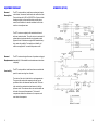
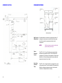
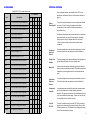
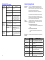
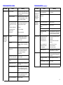
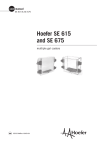
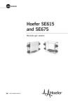
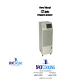
Owner’s Manual SCT Series Portable Air Conditioner 1420 Century Dr., Suite 800 Carrollton, TX 75006 Telephone: 972-242-0007 1-800-683-7768 6116 Westline Drive Houston, TX 77036 Telephone: 713-673-0001 Fax 972-242-0378 THANK YOU! Thank you for choosing Spot Cooling System’s SCT series of portable air conditioners. Spot Cooling is a solutions-based manufacturer dedicated to the development of high-performance air conditioners. Please read This Manual which will describes the unit features and explains how to set-up, operate and maintain your SCT series air conditioner. If you have comments or suggestions on how to improve the SCT series of portable air conditioners please let us know. Our most important source of information for product improvement is from our customers. Please give us a call at 972-242-0007 or email us, [email protected]. Warning! Improper installation, adjustment, alteration, service, or maintenance can cause injury or property damage. Please read this instruction manual before installing, operating or servicing the Extracooler SCT Series unit. This manual is the property of the owner. Leave this manual with the unit when set-up and start-up are complete. SpotCooling Systems reserves the right to change design and specifications without prior notice. TABLE OF CONTENTS Unit Specifications ....................................................................... 1 SCT Series Components .............................................................. 2 Equipment Checklist .................................................................... 3 Standard Features........................................................................ 5 Optional Features ......................................................................... 6 Installation Instructions............................................................... 7 Unit Operation ............................................................................... 8 Preventative Maintenance .......................................................... 9 Troubleshooting Guide .............................................................. 11 Installing Replacement Parts ................................................... 14 Accessories ................................................................................. 16 Schematics .................................................................................. 18 Warranty ...................................................................................... 22 i WARRANTY UNIT SPECIFICATIONS Rating Information Specification SCT-14 SCT-18 SCT-30 SCT-42 SCT-83 SCT-83B Cooling Capacity, BTU/hr1 ( (Ton) 14,000 (1T) 17,600 (1.5T) 29,700 (2.5T) 42,200 (3.5T) 83,500 (6.9T) Power Supply2, volt/hertz/phase/amps 115/60/1/15 115/60/1/15 230/60/1/20 230/60/1/30 230/60/1/60 460/60/3/20 Thermostat Control Mechanical Mechanical Mechanical Mechanical Mechanical TX Valve TX Valve TX Valve TX Valve TX Valve Total Power Consumption, kW 1.3 1.4 2.9 4.2 8.7 9.3 Current Consumption, amps 11.7 12.0 12.5 18.3 37.8 13.2 Recommended Circuit amps 15 15 20 30 60 20 NEMA plug type 5-15P 5-15P 6-20P 6-30P Hard wired Energy Efficiency Rating 10.4 12.8 10.3 10.0 8.9 8.3 Evaporator CFM, free discharge 350 600 750 1,200 2,300 Condenser CFM 500 1,000 1,000 1,500 3,900 Compressor Type Hermetic rotary Hermetic rotary Hermetic rotary Hermetic rotary Hermetic scroll 0.10 0.10 0.10 0.10 0.50 Maximum Duct Length, ft 40 40 40 40 40 Condensate-pump head, ft 15 15 15 15 15 Operating Limits (min-max) °F 65-105 65-110 65-105 65-105 65-110 Sound Level, dB 57 63 63 67 71 R-22 Charge, oz 32 52 54 80 110 29 x 28 x 41 30 x 28 x 51 42 x 30 x 70 251/305 336/395 650/685 Metering Device Maximum esp, in wc L x W x H, in Weight, net/ship lb 26 x 20 x 34 29 x 28 x 41 163/205 1—Rating conditions: 95°F at 60% RH. 1 232/286 2—Electrical ratings based on UL 484. Limited Warranty Spot Cooling warrants to its authorized distributor or end-user, each new SCT series portable air conditioner to be free from defects in material and workmanship for a period of one (1) year from date of purchase. The sole obligation of Spot Cooling under this warranty will be to furnish, without charge, a replacement part for a defective part. This warranty does not include installation, transportation, or postage costs associated with installing the replacement part. This warranty does not apply to equipment that has been damaged by accident, negligence, or misapplication or has been altered or modified in any way. This warranty only applies to the original purchaser. In order for this warranty to become effective, the warranty registration card, delivered with the unit, must be completed and returned to Spot Cooling within 30 days of purchase and delivery. Any claim under this warranty should be first presented to and processed by the authorized distributor from whom the equipment was purchased. To the extent permitted by law, this warranty is expressly in lieu of any other warranties, either expressed or implied, made by Spot Cooling, Incorporated. Spot Cooling assumes no liability in any event for lost profits or revenue, loss of equipment, loss of use of equipment, loss of software, loss of data, costs of substitutes, claims by third parties, or otherwise. This warranty gives you specific legal rights and you may also have other rights, which may vary from state to state. 22 SCHEMATIC (SCT-83B) 21 SCT SERIES COMPONENTS 2 EQUIPMENT CHECKLIST General Description SCHEMATIC (SCT-83) The SCT series portable air conditioners are designed to spot cool industrial, commercial, institutional, and construction sites. Five models provide 14,000 to 83,000 BTU/hr. Options include discharge nozzles to direct conditioned air precisely where needed, and flexible duct to transfer condenser hot air either outside or to an adjacent area. The SCT series are completely self-contained and housed within an insulated cabinet. The unit’s exterior is constructed of galvanized steel and protected with a tough powder-coated, polyester finish. All models are equipped with standard heavyduty casters for portability. For simplicity and reliability, all models are supplied with a manual temperature control. The SCT series are designed for ease of operation an drugged dependability. Follow installation and maintenance instructions Requirements completely. General Serviceability The SCT series portable air conditioners have removable side panels for easier servicing from all sides. The interior of the unit is divided into four sub-compartments. The upper right encloses the evaporator coil and fan, and provides access to the thermostat and fan switch. The lower right contains the condensate tank and access to the highpressure switch. The condenser fan on air-cooled models can be found in the upper left compartment. The lower left compartment encases the condenser coil, compressor, and most electrical components. 3 20 SCHEMATIC (SCT-18) STANDARD FEATURES High-Pressure Safety Switch All models feature a manual reset, high-pressure switch. If refrigeration circuit pressure exceeds control limits, power shuts off to protect the compressor and other critical components. NOTE: 19 Wait four minutes to restart unit after highpressure safety switch trips. Freeze Protection Control The SCT-14, 30, 42, and 83 models are equipped with an automatic freeze protection control. This control turns the compressor off if moisture on the evaporator coil freezes and blocks the coil. Normal cooling operation resumes when the temperature rises and the ice melts. Short Cycle Protection Timer The SCT14, 30, 42, and 83 models are equipped with a short cycle protection timer. The timer provides a five-minute delay before the refrigerant compressor restarts. Under normal conditions, no adjustments are necessary. 4 SCHEMATIC (SCT-14, 30, 42) STANDARD FEATURES Manual TemperatureControl System The manual temperature control system allows you to set the desired temperature by simply rotating the WARMER/ COOLER dial either left or right. The supply air fan can be set to run continuously whether the cooling circuit cycle is on and off, or can be set to cycle on and off with the cooling circuit. Filter All units are equipped with removable, washable, aluminummesh air filters. Located behind the return-air and discharge-air grills, these can be removed and easily cleaned. Condensate Tank A five-gallon, polyethylene tank in the lower-front compartment of the unit collects evaporator-coil condensate moisture. When full, the weight of the tank activates a cutout switch, turning the refrigeration circuit OFF and illuminating the condensate tankfull light on the unit’s front. The tank is readily accessible behind a hinged door. Simply remove, drain, replace, and restart. NOTE: 5 The unit will not operate unless the tank is drained periodically. An optional condensate pump is available for continuous operation. 18 ACCESSORIES OPTIONAL FEATURES Call 800-683-7768 to order accessories. Several optional features are available for the SCT series portable air conditioners. Refer to the Accessories section on page 16. SCT SERIES Part Description NK-1 Two, 4-in nozzles with attachment kit NK-2 Two, 6-in nozzles with attachment kit NK-3 Two, 8-in nozzles with attachment kit CK-1 10-in ceiling discharge kit CK-2 14-in ceiling discharge kit CK-3 14-in ceiling discharge kit CK-4 20-in ceiling discharge kit PC-1 Condensate pump, 115V PC-2 Condensate pump, 208/230V CP-1 10-in condenser return-air plenum CP-2 14-in condenser return-air plenum CP-3 14-in condenser return-air plenum CP-4 20-in condenser return-air plenum EP-1 10-in evaporator return-air plenum EP-2 14-in evaporator return-air plenum EP-3 14-in evaporator return-air plenum EP-4 20-in evaporator return-air plenum DA-6 6-in cold air supply duct adapter DA-10 10-in cold air supply duct adapter DA-14 CD-60 17 14 18 30 42 83 X X X Ceiling Discharge Kit X X X Condenser discharge air can be removed from the conditioned space with flexible duct. Use 40-ft maximum for all models. Allow six feet for every 90 degrees bend. Do not exceed 0.10-in wc (water column) external static pressure at the condenser. X X The optional ceiling discharge kit comes complete with flexible duct and a 2-ft by 2-ft ceiling-tile adapter which allows condensed air to be vented to the plenum area above a suspended ceiling. X X Condenser Return-air Plenum The optional condenser return-air plenum attaches to the rear of the unit and provides an adapter to connect flexible duct. Supply Duct Adapter The optional supply duct adapter attaches to the evaporator air grill and allows the ability to connect a flexible duct. Nozzle Kit A dual-nozzle, discharge-air assembly optimizes the ability to direct cool air precisely where needed. The flexible nozzles are attached to a mounting plate that fits over the evaporator-air grille. Evaporator Return-air Plenum The optional evaporator return-air plenum attaches to the front of the unit and provides an adapter to connect flexible duct. X Condensate Pump Kit A condensate pump automatically drains the condensate tank by removing evaporator-coil water allowing continuous operation. The pump is connected to the condensate drain and to the air conditioner’s power supply. A hose runs from the unit to a convenient drain or outdoor location. 14-in cold air supply duct adapter X Cord Kit (SCT-83) 6-ft NEMA 6P-50 cord kit X The cord kit simplifies wiring for model SCT-83 by providing a plug and socket assembly that is wired directly to the unit and the main power source. This allows the use to plug and unplug the unit for maintenance or storage. X X X X X X X X X X X X X X X X X X 6 ACCESSORIES INSTALLATION INSTRUCTIONS Before Installing Check unit for damage. Air conditioners are inspected at the factory. If any damage has occurred, save the packaging and file a claim with the delivering carrier within fifteen working days. The SCT series requires minimal installation. Plug unit in proper NEMA receptacle, and it begins to cool immediately. Model Receptacle SCT-14 SCT-18 115V 15A/115V NEMA 5-15P NEMA 5-15R SCT-30 208/230V 20A/230V NEMA 6-20P NEMA 6-20R SCT-42 208/230V 30A/230V NEMA 6-30P NEMA 6-30R SCT-83 460/3 Electrical Supply Plug Configuration Hardwired Determine the proper power by checking unit’s rating plate. Refer to the Specifications section on page 1 for voltage and fuse requirements. Use wall outlets and receptacles found in the table above. Operating unit on improper voltages voids the warranty. NOTE: Extension cords may be used if rated at a minimum 120V, 20-amp for models SCT-14 and SCT18 - or - 230V, 30-amp for model SCT-42. Extension cords can NOT be used with the SCT-83. 7 16 INSTALLING REPLACEMENT PARTS Fan Motors (SCT-14 thru SCT-42) UNIT OPERATION 1. Disconnect power from unit. 2. Remove cabinet’s side panels. Fan 1. Place unit on level surface. 3. Disconnect evaporator motor wires at the connector plug. 2. Plug unit in. 4. Disconnect condenser motor wires at the connector plug. 3. Press the COOL/FAN on switch for continuous fan operation. The cooling circuit will cycle on and off. 5. Remove unit’s top and disconnect thermostat at the connector plug. 6. Remove screws securing blower mounts. All screws are external and visible. 7. Remove motors and blower and assemblies. 8. Remove blower and fan assembly. 4. Press the COOL/FAN AUTO switch for cycling the fan operating on and off with the cooling circuit. Cooling Cycle 1. Set the desired temperature by adjusting the WARMERCOOLER dial from 68°F - 115°F. 9. Install new motors, reversing the removal process. NOTE: Fan Motors (SCT-83) Wait 4 minutes between turning cooling mode off and on. 1. Disconnect power from unit. 2. Remove cabinet’s side panels. 3. Disconnect wires from motor that needs to be replaced. 4. Disconnect belt from drives. 5. Remove bolts holding motor onto motor mount. 6. Remove sheave from motor. 7. Install new motor, reversing the removal procedure. 8. Adjust sheave and belt tension as outlined in preventative maintenance. Red Indicator Light 1. Disconnect power from unit. 2. Disconnect wires from control panel, bend tinnerman clip holding light, and pull out. 3. Install new light, reversing the procedure. 15 8 10 PREVENTATIVE MAINTENANCE The SCT series provides maximum performance and reliability with minimum maintenance. The refrigeration and electrical circuits of the system should be serviced by qualified technicians only. To prolong the life of the unit, perform regular maintenance as described below. Filters INSTALLING REPLACEMENT PARTS Ceiling Panel panel duct kit Duct Kit 1. Secure one end of the duct to the ceiling panel adapter and the other end over the unit’s duct collar. 2. Place the ceiling panel adapter under suspended ceiling panel’s framework directly above unit. A clogged filter causes the unit to operate at reduced efficiencies. Inspect filter every six weeks, or more, if operating in a dirty environment. The evaporator’s washable-aluminum filter is located behind the return-air grille, and can be easily removed by pulling out the grille, opening the return-air grille and slowly lift towards hinge. The condenser’s washable aluminum filter is located in the lower back of the unit. Remove by releasing the retaining clip and pull out. Wash filters periodically by placing them in a dishwasher, or soak in a solution of warm water and detergent for ten minutes. Rinse clean with hot water, shaking excess moisture from filter to dry. Blower Motors The blower motor has permanently lubricated ball bearings and require no lubrication. Inspect fan for buildup of dirt on blades. Clean as needed. Coil Cleaning Clean evaporator and condenser coils using compressed air. Condensate Pump 1. Disconnect unit from power source before attempting to service or remove any component. 2. Be sure floats move freely. Clean as necessary. 3. Remove floats and check for obstructions. Clean as needed. 4. Clean tank with warm water and mild soap when mineral deposits are visible. 5. Check inlet and outlet piping. Clean as necessary. Be sure there are no kinks in the lines that can inhibit flow. 6. Clean exterior with a damp cloth. Do not allow water to enter condenser fan outlet or the thermostat. 9 Condensate Pump 1. Unplug unit from power source. Remove condensate tank and hose from drain pan. 2. Place condensate pump on condensate tank shelf. Align holes in shelf with mounting slots in molded tank. Secure pump to condensate tank shelf using two supplied sheet metal screws. 3. Remove electrical plug and jumper wire from receptacle located on bulkhead next to the service fittings. 4. Connect condensate pump’s power plus to receptacle. 5. Install hose from drain pan to the pump inlet. 6. Remove plug from hole in side of unit. 7. Install drain hose from condensate pump outlet through hole in side of unit to a convenient drain or outdoor location. 14 PREVENTATIVE MAINTENANCE TROUBLESHOOTING continued Problem Cause Water leaks from Leaky drain pan pan Evaporator coil freezing and shuts unit down Unit not delivering proper airflow (SCT-83) Remedy Replace pan. Drain plugged Check and clear obstruction. Loose evaporator, drain, or condensate pump hose Tighten connection. Defective condensate pump or excessive lift n pump If elevation exceeds 15-ft, a larger pump is required. Pump does not operate properly if combination of height and length of drain exceeds 15-ft. Change pump, if defective. Unit not on level surface Level. Evaporator exhaust screen obstructed Remove obstruction. Freeze protection control not operating correctly (SCT-14, 30, 42, and 96) Check that control is securely attached to evaporator coil’s outlet and that insulation is in place. Check wiring connections to freeze protection control. Drive belt damaged or not adjusted correctly Check condition and adjustment of evaporator and condenser fan belts and sheaves. Adjust belts for 3/16-in deflection. Belt Tension (SCT-83) The SCT-83 is equipped with adjustable sheaves on the evaporator and condenser fans. Conditioned-air and condenser-air are controlled by using double-inlet, forward-curved fans driven by belt and sheave combination. Adjust belt tension for 3/16-in deflection, with 2 lbs force. The evaporator-fan and condenser-fan sheaves are factory preset and should not be adjusted. Periodically check that sheaves are securely fastened to blower shafts by tightening the set -screw on the stationary half of sheave. Sheave Adjustment If necessary, adjust pitch by loosening the set screw on the adjustable half of the sheave. Turn sheave clockwise until it touches the stationary shaft. To adjust evaporator motor sheave: Turn sheave counterclockwise 3-1/2 turns and tighten set screw. To adjust condenser motor sheave: Turn sheave counterclockwise 4 turns and tighten set screw. Maintenance Frequency The following table shows maintenance items and frequency. Item 13 Frequency Maintenance Action Filters Monthly Inspect. Replace/wash if dirty or clogged. Blower motor Monthly Inspect for buildup of dirt on blades. Clean as needed. Evaporator / condenser coil Monthly Inspect for buildup. Blow with compressed air as needed. Condensate pump Monthly Inspect float operation. Inspect for mineral deposits. Clean as needed. Belt (SCT-960) Monthly Check tension. Adjust as needed. Sheave Monthly Inspect sheaves are securely fastened. Tighten as needed. 10 TROUBLESHOOTING GUIDE Problem Cause Unit does not run Power interruption Thermostat inoperable Electrical Panel 24-Volt transformer defective (SCT-14, 30, 42, and 83) Contactor coil defective Contacts stuck open, Evaporator fan runs, but compressor and condenser fan do not start 11 TROUBLESHOOTING continued burned or dirty Wires loose Remedy Check external power supply. Look for blown fuses or tripped circuit breakers. Reset or replace. Setting may be too high. Check and reset. Thermostat may be out of calibration or defective. Replace. Check output of transformer. If not supplying 24 volts, replace. Problem (continued) Evaporator fan runs, but compressor and condenser fan do not start Compressor runs, but fan does not run Replace. Correct or change. Tighten connections. Low voltage Check power supply for voltage outside the range of 106 to 126-V on 115-V units and 187 to 253-V on 208/230-V units. Thermostat Examine control unit for loose wires and tighten. Wait four minutes before restarting. High-pressure control switch turning unit off Clean condenser coil filter. Clean condenser discharge screen. Check for defective condenser fan motor. Replace if necessary. Restricted duct. Short cycle timer not timed out (SCT-14, 30, 42, and 83) Wait 5 minutes for timer to allow compressor to restart. Compressor contactor open or burned Replace. Refrigerant leak—no freon Locate leak and repair. Evacuate unit and recharge. Loose or defective wires Check for loose or shorted conductors. Secure contact between wires and connectors. Repair or replace as necessary. Defective compressor Check for shorts, opens, and grounds. Compressor replacement should be done by a service technician. Tank-full, cut-out switch defective Check and replace. Insufficient cooling Cause Remedy Condensate tank full, or red indicator light defective Check tank and replace red indicator light if defective. Shorted or open run capacitor(s) Replace. Open fan motor coil circuit Replace fan motor. Shorted or open fan motor capacitor Replace capacitor. Loose or defective wires Trace and repair. Overload relay tripped (SCT-83) Open rear access cover, push in red manual reset button on overload relay, wait 5 min for compressor to restart. Insufficient airflow through evaporator coil due to: Dirty air filter in unit See Preventive Maintenance section of this manual. Clean filter Dirty evaporator coil Clean filter with vacuum cleaner Ice on evaporator coil Obstructed air intake Low refrigerant Defrost. Run on fan only. Remove obstruction. Repair leak in system. Unit improperly sized Check to assure unit is sized for load. Add supplemental unit if required. Copper tubing vibrating Adjust by bending slightly to firm position. Separate tubes touching cabinet or each other. Loose cabinet or internal component Check and tighten loose screws. Machine vibrating-out of level Level unit base. Blower motor bearing defective Replace blower motor. and hose. Noisy operation 12