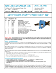
1
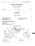
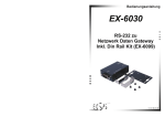
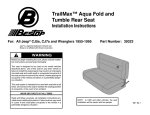
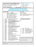
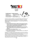
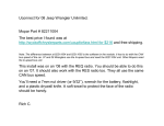
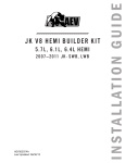
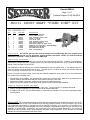
Part #: RR231
Page 1 of 11
Technical Support (318) 388-0816
NP231 SHORT SHAFT "FIXED YOKE" KIT
KIT CONSISTS OF:
No.
Qty
Part No.
Description
1.
2.
3.
4
5.
6.
7.
8.
9.
10.
11.
12.
1
1
1
1
1
1
1
2
1
1
1
1
51-7905
52-7905
300474
300475
300476
300480
300625
300627
716318
716464
716465
716751
TAILHOUSING, DIECAST
SHAFT, MAIN OUTPUT
SEAL WASHER, REAR YOKE
YOKE, C.V. REAR
NUT, REAR YOKE
SEAL WASHER, FRONT YOKE
RING GEAR, SPEED-OSNAP RING, SPEED-O- RING GEAR
BEARING, 207 OPEN BALL (No Snap Ring)
SNAP RING, 207 BEARING
RETAINER RING, MODE
SEAL, TAILHOUSING
SPECIAL NOTE: On vehicles that have the vacuum actuator on the tailhousing, we have supplied a tailhousing that will provide you the necessary vacuum actuator connection. NOTE: The shift rail must be
shortened to protrude 1" when in 4WD low or 4WD high.
INSTALLATION PROCEDURES:
Every effort has been made to make sure your kit fits and works right the first time. However, if you happen to
experience a problem with your kit, please contact us at our technical assistance line at (318) 388-0816, Monday
through Friday 8:00 AM to 6:00 PM CST.
The installation of this kit requires you to nearly disassemble the entire transfer case. If your transfer case is in
need of a rebuild, now is the perfect time to do it. To install this kit, it is easier to remove your transfer case and
set it on end upon a workbench, but it is not necessary.
Here are a couple of points to keep in mind that will make the installation much easier if you've never disassembled a New Process transfer case:
1. Keep all bolts, nuts, washers, etc. separated into groups as you remove them. Make sure you keep them in a
labeled container that indicates what part of the transfer case they came from.
2. Keep all small parts in separate containers and label as to location and origin.
3. Make sure you have plenty of time and a clean, spacious area to perform the installation.
THINGS TO CONSIDER BEFORE YOU BEGIN:
1. This kit is shipped with a rear 1310 series C.V. type yoke. You will need a C.V. equipped driveshaft.
2. Medium strength threadlocker is recommended on all threaded fasteners.
3. A sealant such as RTV, (like the OEM sealant) is needed and is available from your local Jeep/Dodge dealer.
P/N 82300234.
SPECIAL NOTE: The components packaged in this kit have been assembled and machined for specific type of conversions. Modifications to any of the components will void any possible warranty or return privileges. If you do not
fully understand modifications or changes that will be required to complete your conversion, we strongly recommend that you contact our sales department for more information. This instruction sheet is only to be used for the
assembly of SKYJACKERfi components. We recommend that a service manual pertaining to your vehicle be
obtained for specific torque values, wiring diagrams and other related equipment. These manuals are normally
available at automotive dealerships and parts stores.
Part #: RR231
Page 2 of 11
Technical Support (318) 388-0816
NP231 SHORT SHAFT "FIXED YOKE" KIT
DRIVE SHAFT MODIFICATION:
This job should be performed by a local driveline repair shop capable of balancing the finished assembly.
(Use a C.V. joint & long slip spline style shaft assembly.)
With the vehicle finished and on the ground, measure a straight line between the transfer case output yoke and the
rear pinion yoke center mating flanges. (Fig. A)
T/C OUTPUT
MEASURE
(Fig. A)
DIFFERENTIAL YOKE
For proper C.V. type drive shaft operation, the rear differential should be pointed at the transfer case output yoke under
normal driving load. If install is performed on jack stands, make sure you have supported the vehicle well!
Place the transfer case range selector in the 4L position. Remove front & rear drive shafts and begin at the disassembly procedures. (Step 1, Fig. 1)
SPECIAL NOTE:
The components packaged in this kit have been assembled and machined for specific type
of conversions. Modifications to any of the components will void any possible warranty or return privileges. If you do
not fully understand modifications or changes that will be required to complete your conversion, we strongly recommend that you contact our sales department for more information. This instruction sheet is only to be used for the
assembly of SKYJACKERfi components. We recommend that a service manual pertaining to your vehicle be
obtained for specific torque values, wiring diagrams and other related equipment. These manuals are normally available at automotive dealerships and parts stores.
Part #: RR231
Page 3 of 11
Technical Support (318) 388-0816
NP231 SHORT SHAFT "FIXED YOKE" KIT
(Fig. 1) Yoke Nut Removal
(Fig. 3) Slinger Removed (TJ Illustrated)
(1) Remove Speed-o-drive.
(2) Remove front yoke nut:
(a) Move range lever to 4L position.
(b) Remove front yoke nut with 1-1/8" socket using
an impact wrench. (Fig. 1)
(3) Remove yoke. Note: If difficult, use a
puller. (Discard seal washer).
(4) Remove selector lever. (Fig. 2)
(5) Remove output shaft boot. Spread band clamps
with an Awl. Slide boot off.
(6) Remove slinger, (this one is tough)! Good thing you
won't need this later. (Fig. 3)
(7) Remove stop spacer & snap ring. (Fig. 4)
SPECIAL NOTE: The components packaged in this kit have been assembled and machined for specific type of conversions.
Modifications to any of the components will void any possible warranty or return privileges. If you do not fully understand modifications or changes that will be required to complete your conversion, we strongly recommend that you contact our sales department for more information. This instruction sheet is only to be used for the assembly of SKYJACKERfi components. We recommend that a service manual pertaining to your vehicle be obtained for specific torque values, wiring diagrams and other related equipment. These manuals are normally available at automotive dealerships and parts stores.
Part #: RR231
Page 4 of 11
Technical Support (318) 388-0816
NP231 SHORT SHAFT "FIXED YOKE" KIT
(Fig. 5) Rear Seal Removal
(8) Remove rear seal. Collapse with punch if needed.
(Fig. 5)
(Fig. 6) Rear O.D. Snap Ring Removal
(9) Remove rear bearing retaining rings. (Fig. 6) &
(Fig. 7)
(Fig. 8) Rear Tailhousing Removal
(10) Remove tailhousing bolts with 10mm socket &
remove tailhousing. (Fig. 8)
SPECIAL NOTE:The components packaged in this kit have been assembled and machined for specific type of conversions. Modifications to any of the components will void any possible warranty or return privileges. If you do not
fully understand modifications or changes that will be required to complete your conversion, we strongly recommend that you contact our sales department for more information. This instruction sheet is only to be used for the
assembly of SKYJACKERfi components. We recommend that a service manual pertaining to your vehicle be
obtained for specific torque values, wiring diagrams and other related equipment. These manuals are normally
available at automotive dealerships and parts stores.
Part #: RR231
Page 5 of 11
Technical Support (318) 388-0816
NP231 SHORT SHAFT "FIXED YOKE" KIT
(Fig. 9) Oil Pump Removal
(Fig. 11) Front Drive Chain & Shaft Removal
(11) Disconnect the pump pickup tube visible at lowest point of
tailhousing opening. (Fig. 9)
(a) Remove the pump from the main output shaft.
(b) Inspect the pickup tube "o-ring" in the pump and
replace if needed. The same goes for the front shaft
seal in the pump. DO NOT disassemble the pump; it
is not a serviceable item.
(12) Remove the rear case bolts. A 10mm 12 pt. socket is
needed for the spline head bolt & a 15mm socket for
the remaining bolts. NOTE: The two black oxide finished
bolts are located at the case dowel positions
and require a washer under them.
(14) Front output shaft removal:
(a) Pull the front output shaft out of the front
bearing. (Fig. 11)
(b) Slide drive chain off the rear output shaft and
remove both shaft and chain for cleaning &
inspection.
(15) Rear output shaft removal: (a)Grasp the main shaft
and remove the shaft, drive sprocket and mode hub
assembly.
(Fig. 12) Front Drive Chain & Shaft Removal
(Fig. 10) Rear Case Half Removal
(13) Remove the rear case from the front case by inserting pry
bars at the cast-in locations ONLY! (Fig. 10)
(a) Pry apart evenly to break the sealer bead along the
case mating surfaces.
(b) Remove, clean and inspect the inner case for wear.
(16) Output shaft disassembly:
(a) Remove the mode hub retaining ring with heavy
duty snap ring pliers. (Fig. 12)
(b)Slide remaining components, mode hub & drive
sprocket off shaft.
(17) This is as far into the case you need to go unless
you find foreign material inside usually caused
by a worn or stretched drive chain. You will need to
be the judge.
SPECIAL NOTE: The components packaged in this kit have been assembled and machined for specific type of conversions.
Modifications to any of the components will void any possible warranty or return privileges. If you do not fully understand modifications or changes that will be required to complete your conversion, we strongly recommend that you contact our sales department for more information. This instruction sheet is only to be used for the assembly of SKYJACKEfi components. We recommend that a service manual pertaining to your vehicle be obtained for specific torque values, wiring diagrams and other related
equipment. These manuals are normally available at automotive dealerships and parts stores.
Part #: RR231
Page 6 of 11
Technical Support (318) 388-0816
NP231 SHORT SHAFT "FIXED YOKE" KIT
SKYJACKERfi has supplied two types of NP231 output shafts over the past years. The current production output shaft is similar
to the NP231 shaft found in the "TJ" series Wranglers. This TJ shaft did not use a caged needle bearing on the drive sprocket. We
decided to use this design, since this is the most current design engineered & being produced by New Process Gear.
The earlier short shaft we supplied was similar to the "YJ" series Wranglers. This shaft uses a set of caged roller bearings,
installed in the drive sprocket.
This information is provided to you to verify which style shaft you have so installation is properly performed.
TJ style shaft
Current kit design.
No needle bearings required.
See Page 7 for assembly considerations.
YJ style shaft
Previous kit design.
Needle bearings (P/N 716319) &
thrust washer (P/N 716320) required.
See Page 8 for assembly considerations.
SPECIAL NOTE: The components packaged in this kit have been assembled and machined for specific type of conversions.
Modifications to any of the components will void any possible warranty or return privileges. If you do not fully understand modifications or changes that will be required to complete your conversion, we strongly recommend that you contact our sales department for more information. This instruction sheet is only to be used for the assembly of SKYJACKERfi components. We recommend that a service manual pertaining to your vehicle be obtained for specific torque values, wiring diagrams and other related equipment. These manuals are normally available at automotive dealerships and parts stores.
Part #: RR231
Page 7 of 11
Technical Support (318) 388-0816
NP231 SHORT SHAFT "FIXED YOKE" KIT
Shafts that resemble the TJ
ASSEMBLY CONSIDERATIONS
(Fig. 1A) Drive Sprocket Needle Bearings
These bearings must be removed. Once the bearings are
removed, clean the inside of the drive gear to make sure it is
free of any type of debris.
(Fig. 2A) Pull the Needle Bearings Out
(Fig. 3A) New Main Output Shaft Assembly
(2)
Main shaft assembly:
(a) Clean all components.
(b) Prelube all components with a quality assembly
lubricant. (Fig. 3A)
(c) Slide drive sprocket into position.
(d) Slide mode hub into position.
(e) Install the retaining ring into position after the mode
hub. (Fig. 4A)
(Fig. 4A) (Large) Retaining Ring Installation
SPECIAL NOTE: The components packaged in this kit have been assembled and machined for specific type of conversions.
Modifications to any of the components will void any possible warranty or return privileges. If you do not fully understand modifications or changes that will be required to complete your conversion, we strongly recommend that you contact our sales department for more information. This instruction sheet is only to be used for the assembly of SKYJACKERfi components. We recommend that a service manual pertaining to your vehicle be obtained for specific torque values, wiring diagrams and other related equipment. These manuals are normally available at automotive dealerships and parts stores.
Part #: RR231
Page 8 of 11
Technical Support (318) 388-0816
NP231 SHORT SHAFT "FIXED YOKE" KIT
Shafts that resemble the YJ
ASSEMBLY CONSIDERATIONS
(Fig. 3A) New Main Output Shaft Assembly
(Fig. 1A) Drive Sprocket Needle Bearing Installation
(1)
Component assembly:
(a) Care should be taken not to distort the housed
bearing element when installing the new
bearing. (Fig. 1A)
(b) Press bearings into both sides of the drive
sprocket so they seat just past the inside
chamber. (Fig. 2A)
(c) If you are not comfortable at this point, you
should take this step to a local machine shop.
(Fig. 2A) Installed Needle Bearings in Drive Sprocket
(2)
Main shaft assembly:
(a) Clean all components.
(b) Prelube all components with a quality assembly
lubricant. (Fig. 3A)
(c) Slide drive sprocket into position.
(d) Slide mode hub into position.
(e) Install retaining ring into position after the mode
hub. (Fig. 4A)
(Fig. 4A) (Large) Retaining Ring Installation
CONTINUE TO PAGE 9
SPECIAL NOTE: The components packaged in this kit have been assembled and machined for specific type of conversions.
Modifications to any of the components will void any possible warranty or return privileges. If you do not fully understand modifications or changes that will be required to complete your conversion, we strongly recommend that you contact our sales department for more information. This instruction sheet is only to be used for the assembly of SKYJACKERfi components. We recommend that a service manual pertaining to your vehicle be obtained for specific torque values, wiring diagrams and other related equipment. These manuals are normally available at automotive dealerships and parts stores.
Part #: RR231
Page 9 of 11
Technical Support (318) 388-0816
NP231 SHORT SHAFT "FIXED YOKE" KIT
(Fig. 5A) New Main Output Shaft Assembly
(3)
(4)
Output shaft and drive chain assembly:
(a) Lubricate chain & shaft with ATF.
(b) Insert main shaft assembly into the housed planetary
assembly.
(c) Install the drive chain onto the front output shaft.
(d) Insert them into the bearing. Lift upward and tilt the
shaft toward the main shaft to work the chain into
position. (Fig. 5A)
Make sure the mode spring is in place, seen in the
middle. (Fig. 5A)
(Fig. 6A) Case Half Pre-assembly
(5)
(6)
Rear case assembly:
(a) With all components clean, install oil pump.
(b) Seat the pickup tube into the pump "o-ring". (Fig. 6A)
(c) Prelube the front output shaft bearing located in the
rear case.
Apply a thin film of sealant to the front case. Use a good
RTV, like the OEM sealant, available from your local Jeep
dealer. (Fig. 7A) P/N = 82300234.
(Fig. 7A) Thin film RTV Applied Prior to Mating
Case Halves.
(Fig. 8A) Case Halves Assembled
(7)
Assembly of case halves: (Fig. 8A)
(a) Slide the pump & case into position.
(b) If you have difficulty, check for possible problems.
DO NOT FORCE! Mode fork rail extends through
rear case!
(c) Install all fasteners in their original positions. (Black
bolts at dowel locations!)
(d) Torque evenly to 27-34 N.m (20-25 ft./lbs.)
SPECIAL NOTE: The components packaged in this kit have been assembled and machined for specific type of conversions.
Modifications to any of the components will void any possible warranty or return privileges. If you do not fully understand modifications or changes that will be required to complete your conversion, we strongly recommend that you contact our sales department for more information. This instruction sheet is only to be used for the assembly of SKYJACKERfi components. We recommend that a service manual pertaining to your vehicle be obtained for specific torque values, wiring diagrams and other related equipment. These manuals are normally available at automotive dealerships and parts stores.
Part #: RR231
Page 10 of 11
Technical Support (318) 388-0816
NP231 SHORT SHAFT "FIXED YOKE" KIT
KIT CONSISTS OF:
No.
Qty
Part No.
Description
(Fig. 10A) Bearing Installed
and Retained with the 716464
(Fig. 11A) Seal
(Fig. 9A) Speed-o- Ring Gear Install
(8)
Assemble speed-o- drive
(a) Install retaining ring, located just behind the pump.
(b) Slide ring gear into position.
(c) Install retaining ring behind ring gear. (Fig. 9A)
(10) Short Tailhousing Installation:
(a) Prelube bearing & seal in new short tailhousing
assembly. (Fig. 11A)
(b) Apply sealant to tailhousing, mating surface of rear
case. (thin film)
(c) While supporting main shaft, slide new tail assembly
into position.
(d) Use care when indexing pump outer tabs and
aligning tail assembly for installation. (Fig. 12A)
NOTE: Pull back on the output shaft to seat it
against the rear bearing.
(e) Install the (5) 10mm bolts that retain the tailhousing
and torque evenly to 20-27 N.m (15-20 ft./lbs.)
NOTE: On some NP231 transfer cases, the shift rail must be
shortened. This shift rail protrudes out of the transfer case
and goes into the tailhousing. The new tailhousing has a
pocket depth of 1.125".
Shift your transfer case so the shift rod is protruding the furthest out of the transfer case. If this shifter rod protrudes more
than 1" out of the back side of the transfer case, then the shift
rail must be shortened. Transfer cases that will normally
require this rail to be shortened measure 1.5" (photo above
left).
Using a hack saw or cutoff wheel (and safety glasses), trim the
shift rail shaft so that it protrudes only 1" (photo above right).
SPECIAL NOTE: The components packaged in this kit have been assembled and machined for specific type of conversions.
Modifications to any of the components will void any possible warranty or return privileges. If you do not fully understand modifications or changes that will be required to complete your conversion, we strongly recommend that you contact our sales department for more information. This instruction sheet is only to be used for the assembly of SKYJACKERfi components. We recommend that a service manual pertaining to your vehicle be obtained for specific torque values, wiring diagrams and other related equipment. These manuals are normally available at automotive dealerships and parts stores.
Part #: RR231
Page 11of 11
Part #: RR231
Page 11of 11
Technical Support (318) 388-0816
NP231 SHORT SHAFT "FIXED YOKE" KIT
(Figures 13A) Final Installation
(11) Yoke & Seal Washer installation: (This will apply to both Front & Rear yoke assembly)
(a) Slide the yoke seal into position on the shaft thread.
(b) Lube yoke with ATF.
(c) A little trick to keep the spline seal in good shape is to slide the yoke half way on and walk the yoke
into position with the retaining nut. (Be sure to apply thread-lock to the retaining nut). Torque to 140
150 ft./lbs. with 1-1/8" socket.
(d) Install your stock speedometer housing into your new tailhousing. A touch of RTV Blue silicon around
the "o"-ring will help seal this area.
(12) Fill to recommended level with ATF.
(13) Reconnect all exterior items: driveshafts, 4WD switch, speedometer cable, etc.
(14) Happy Trails!
SPECIAL NOTE: The components packaged in this kit have been assembled and machined for specific type of conversions.
Modifications to any of the components will void any possible warranty or return privileges. If you do not fully understand modifications or changes that will be required to complete your conversion, we strongly recommend that you contact our sales
department for more information. This instruction sheet is only to be used for the assembly of SKYJACKERfi components. We
recommend that a service manual pertaining to your vehicle be obtained for specific torque values, wiring diagrams and other
related equipment. These manuals are normally available at automotive dealerships and parts stores.
Part #: RR231
(BULLETIN)
Technical Support (318) 388-0816
ATTENTION!
NOTE: If your jeep transfer case output shaft is equipped with a harmonic
balancer, this balancer must be
removed with a puller at step #5 during disassembly.
The harmonic balancer is pressed
onto the output shaft, a balancer
puller will be required to remove this
item without damage. The balancer
has three threaded holes to aid in this
disassembly. (see arrow at right)
Refer to repair manual during this
process.This balancer will not be required
once the fixed yoke kit is installed.