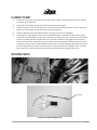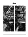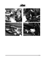
1
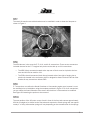
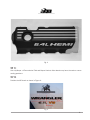
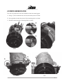
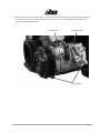
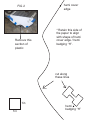
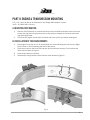
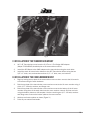
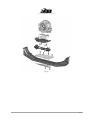
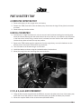
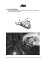
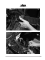
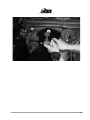
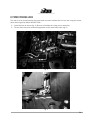
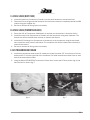
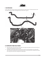
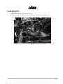
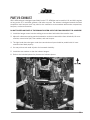
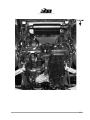
5 . 7 L , 6 .1 L , 6 . 4 L h e m i
2 0 0 7 — 2 0 11 J K - s w b , l w b
AEV30207AA
Last Updated: 08/30/12
INS TALLATION GUIDE
JK v8 Hemi builder kit
table of contents
1. Overview1
2. Engine and Transmission Mounts
9
3. Wiring13
4. Battery Tray
17
5. Steering Shaft Relocation
23
6. Plumbing29
7. Exhaust35
PLEASE NOTE THAT THIS KIT HAS NOT BEEN TESTED TO COMPLY WITH FMVSS STANDARDS
AND MUST NOT BE INSTALLED IN ANY NEW VEHICLE PRIOR TO DELIVERY TO THE END USER.
WHILE ALL CORRECT EMMISSIONS EQUIPMENT IS DESIGNED TO BE INSTALLED WITH THIS
KIT, THIS KIT MAY STILL NOT BE LEGAL FOR ON-ROAD USE IN ALL STATES OR COUNTRIES
AND AS SUCH IS CURRENTLY INTENDED FOR OFF-ROAD USE ONLY. IT IS THE USERS
RESPONSIBILITY TO COMPY WITH ALL REGULATIONS.
AEV DOES NOT RECOMMEND ANY MODIFICATIONS TO HEMI ENGINES OR TRANSMISSIONS.
TECH SUPPORT CAN NOT BE PROVIDED FOR ANY CONVERSIONS USING AFTERMARKET
PERFORMANCE PARTS INCLUDING BUT NOT LIMITED TO CAMSHAFTS, HEADS, EXHAUST
MANIFOLDS, AFTERMARKET EXHAUSTS, INTAKES, THROTTLE BODIES, PERFORMANCE
ECU CALIBRATIONS, STROKER KITS, SUPERCHARGERS, TURBOCHARGERS, SHIFT KITS
OR ANY OTHER NON PRODUCTION ITEM.
ii
PLEASE READ BEFORE YOU START
TO GUARANTEE A QUALITY INSTALLATION, WE RECOMMEND READING THESE INSTRUCTIONS
THOROUGHLY BEFORE BEGINNING ANY WORK. THESE INSTRUCTIONS ASSUME A SUBSTANTIAL
AMOUNT OF MECHANICAL ABILITY AND ARE NOT WRITTEN NOR INTENDED FOR SOMEONE NOT
FAMILIAR WITH AUTO REPAIR.
This product is covered under the AEV Parts Limited Warranty, a copy of which can be found at aev-conversions.com/warranty.
iii
part I: Overview and Tips
Congratulations on purchasing your AEV JK HEMI Installation kit. These instructions have been
written for shops or DIY individuals with experience in general mechanics and welding. AEV also assumes that this kit will be installed in a shop environment with access to general shop equipment.
If you are not familiar with JK systems, please reference the Jeep Service Manual available at any
Chrysler dealership.In order to help facilitate installation, we have composed a series of tips below:
This kit requires a 2007-2010 Grand Cherokee engine. If using a 2011 engine you must change
the water pump and crank pulley to ‘07-‘10 parts.
TIP 1:
Although it is not required, AEV recommends using a two post hoist to remove the body from the
vehicle. The Jeep JK Wrangler was designed by Chrysler to have the body and chassis built as two
complete assemblies which are then mated together on the assembly line, because of this; removal
of the body only requires about 45 minutes. The general procedure is outlined below:
1.
2.
3.
4.
5.
6.
7.
8.
9.
10.
11.
12.
13.
14.
15.
16.
17.
18.
19.
20.
21.
22.
Discharge the AC system
Disconnect the steering shaft at the firewall.
Disconnect the appropriate brake lines at the ABS Module.
Disconnect the battery harness from the battery, firewall, and right front fender.
Unplug the 34 way powertrain connector at the firewall (C100) and the 34 way Chassis connector (C300) on the right hand side of the radiator.
Unplug the PCM (C1, C2, C3, and C4.) Remove the harness from left front fender and firewall.
Disconnect the front left O2 sensor located below the master cylinder (pre-2011) or on the
firewall (post-2011.)
Drain and disconnect the radiator and heater hoses.
Disconnect the transmission cooler lines at the radiator.
Remove the power steering reservoir from the body.
Disconnect the vacuum line from the brake booster and firewall.
Disconnect the ground strap from the hood and firewall.
Remove the battery tray and air filter
Remove the heater core hoses from the engine.
Remove the drive shafts
Remove the trailer harness if equipped.
Remove all the body mounts
Disconnect the emergency brake cables at the rear axle.
Disconnect the transmission and transfer case cables
Disconnect the fuel fill hose.
Disconnect all vapor lines at the purge valve.
Disconnect the top of the rear axle vent line.
1
Once the body is separated, it is easy to remove the stock powertrain, weld in the new mounts
and to install the assembled 5.7, 6.1L, or 6.4L powertrain and exhaust into the chassis. While
the body is on the hoist, the completed cooling module, and steering modifications can be completed. The body is then mated back to the chassis using the reverse procedure, the harnesses
are plugged in, the brake lines are hooked back up and bled, the radiator hoses can then be
connected and the vehicle can be filled with fluid and started.
TIP 2:
There are several variations of sensors, alternators, water pumps, crank pulleys, and power
steering pumps used in different applications from 2005 onward. Please check that you have all
the correct parts listed in the Bill of Materials provided on our website. Using the wrong part can
cause serious damage to other components.
TIP 3:
The exhaust system is designed to fit the 5.7L motor in a stock application. 6.1L and 6.4L motors use the 5.7 exhaust but will be required to use the 5.7L Manifolds, Gaskets, and bolts also
listed in the Bill of Materials. The routing has been fitted assuming a stock suspension and bumpers. The use of aftermarket suspensions, bumpers or other components may require modifications to the exhaust system or other components. Two Door Wranglers will need a section of tail
pipe cut out of the system.
TIP 4:
Jeep Wranglers being converted from Manual to Automatic Transmissions will require AEV Part
#31001027AA which is an additional wire for the body side of the harness. The other parts required to perform the manual to automatic conversion are listed in the Bill of Materials.
TIP 5:
Four door wranglers can use the stock driveshaft’s front and rear; two door models will need a
new or modified rear driveshaft.
TIP 6:
WK and XK powertrains come with a rear sump aluminum oil pan (plastic pan on 2011s must be
changed.) This pan will work but is easily damaged off-road. As an option, a steel pan is available from the Dodge Ram and all parts are listed in the supplied Bill of Materials. LX powertrains
come with a front sump aluminum pan and will need to be changed to the steel pan. Be sure to
reference a 5.7 manual regarding the “Torque To Yield” main bearing cap bolt and always use a
new bolt.
2
TIP 7:
The stock JK transfer case cable bracket must be modified in order to clear the floorpan as
shown in Figure 1.
Fig. 1
TIP 8:
The AEV Harness is the same for 5.7L, 6.1L, and 6.4L conversions. There are two connectors
included that are for the 5.7L engines only and must be tied up on 6.1L conversions.
• The MDS (Gray) connector located at the top rear of block must be zip tied to the harness and will not be used for 6.1L.
• The EGR solenoid connector (black 6-way) located at the front right of engine has a
plastic clip located in the connector which is designed to fasten under the AEV air filter
bracket on any conversions without EGR.
TIP 9:
5.7 conversions can utilize the Grand Cherokee or Commander engine cover however it must
be modified prior to installation using the template provided in Figure 2. For 6.4L conversions,
you can utilize the Grand Cherokee valve covers but the driver’s side needs to be modified.
See Figure 3 illustrating the portion to be removed.
TIP 10:
The new position of the V8 motor on top of and in front of the front axle causes approximately
430 lbs of weight to be shifted to the front axle and suspension. Stock springs will see approximately 1” of drop, aftermarket springs will vary depending on the manufacturer of the springs.
3
Fig. 3
TIP 11:
Use only Mopar +4 Transmission Fluid and Mopar Coolant. Other brands may harm the seals or cause
cooling problems.
Tip 12.
Position the V8 Decals as shown in Figure 4.
Fig. 4
4
AC compressor modification
The 3.8L AC Compressor must be modified to clear the steering gear.
A. Using a 7/8-in countersink bit, drill out the factory hole as shown.
B. Use a grinder to bevel the corner of the mounting point as shown.
C. Grind the raised portion of housing flush as shown.
a.
B.
before
after
C.
C.
before
after
5
A. Mount AC compressor to engine block. Use the supplied flat head bolt in the upper mounting hole,
a factory bolt in the lower, and a factory bolt in the rear with the supplied spacer between the
compressor and engine block.
supplied bolt
supplied spacer
factory bolts
6
FIG 2
Remove this
section of
plastic
hemi cover
edge
* Retain this side of
the paper to align
with shape of hemi
cover edge / hemi
badging “H”.
cut along
these lines
1in
1in
hemi
badging “H”
8
Part II: Engine & transmission mounting
5.7L, 6.1L, and 6.4L WK or XK Powertrains with Dodge 4WD Adapter in place.
2007+ JK—SWB, LWB, LHD only
a. mounting preparation
1.
2.
After the 3.8L Powertrain is removed, disconnect the front ABS connectors at the frame and
remove the right side wiring harness bolt on clips that are located on the frame behind the
right side shock tower.
Cut off the OE engine mounts from the frame and clean up the area with a sanding disc.
b. installation of the engine mounts
1.
2.
3.
4.
Each engine mount has an L or R inscribed into the metal indicating the Left from the Right.
There is also an arrow indicating the front of the mount.
Place the mounts on the frame rail and line up the oval holes precisely. Tack in place and
finish weld as shown in Figure 1.
Paint all bare areas as required.
Reinstall the wiring harness mount with the stock hardware (Figure 2.)
Fig. 1
9
Fig. 2
c. installation of the transmission mount
1.
2.
3.
All 5–45 Transmissions must have the 3/4 Ton or 1 Ton Dodge 4WD adapter
(Mopar 52119433AB) installed prior to the transmissions mount.
Install the AEV Mount to the 4WD Adapter on the transmission using the stock bolts.
Install the stock JK transmission isolator to the AEV Transmission Mount using the two
3/8” x 1” bolts, nuts, and washers and two 1/2” x 1” bolts, nuts, and washers.
D. installation of the cross-member mount
1.
2.
3.
4.
5.
Begin by bolting the top plate of the transmission cross member mount to the JK transmission isolator using the stock hardware.
Bolt the top plate of the transmission cross member mount to the JK cross member using 4
of the 1/2”–13 bolts, washers, and flange nuts.
Bolt the top plate of the transmission cross member mount to the bottom of the JK cross
member using three of the stock bolts into the cross member nutserts. Drill out one hole
using the bottom plate as a drill template. Use the remaining two 1/2”–13 bolts, washers
and flange nuts to secure the bottom plate to the cross member.
Weld top and bottom plates as shown (Figure 3.)
Paint any raw material and welds.
10
Fig. 3
11
Part III: wiring harness installation
Every AEV HEMI JK Wiring Harness is 100% computer checked for quality and accuracy before
shipment. The harness is installed and routed the same way as a factory Grand Cherokee or
Commander Powertrain Harness; if more information than what is provided in this manual is
required, please refer to any 2007+ WK or XK Factory Service Manual.
a. harness to powertrain
1.
Lay out the harness on the ground as shown, with the PCM Connectors to the left when
viewed from the driver’s position. The injector connectors will be towards the front. Orient
the harness next to the assembled powertrain so that the routing can be easily seen. The
part of the harness that connects to the powertrain is an “H” shape and is designed to have
the center portion (the bar) of the “H” located and centered at the top of the area where the
engine and transmission interface.
2. Install the braided ground strap from the right to the left and then leave the loose end so
that it will attach to the firewall stud on the right side of the vehicle.
3. Begin plugging in the left side injectors and coils, proceed around the front of the engine
and down to the knock sensor.
4. Route the right side of the injector harness forward and then down behind the alternator
plugging in the Cam, Crank, Oil Temp, and Knock sensors.
5. Plug in the left side of the transmission, including the Input Speed Sensor, Solenoid Assembly, Out put Speed Sensor, and Transfer Case Mode Selector.
6. Continue by installing the right side of the transmission by securing the O2 Sensors and the
Pressure Transducer.
7. Secure all O2 Sensors and zip tie the harness securely to the powertrain. Do not over
tighten zip ties—you may damage the harness.
8. Carefully route the starter wire as shown. The ground stud located behind the starter is
reused from the 3.8L.
9. On 6.4L engines, connect the Variable Runner Intake. Other engines be sure to zip tie this
connection to the harness so it is out of harm’s way.
10. Re-use the factory 3.8L Battery Harness.
12
b. harness to body
1.
2.
3.
4.
5.
Install the 10-way gray connector to the inside of the firewall using the double push-pin fastener
included in the connector.
Install the C100 34-way connector to the firewall bracket like stock.
Route the harness over the AC Liquid line and around to the PCM/Computer. You can reuse the
factory zip ties to fasten the harness to the washer bottle tray
Plug the harness into the AEV PCM and then into the AC Pressure Transducer.
Install the AEV 4-way Pigtail Harness into the PCM/Computer connector C3 (body side—white)
connector by releasing the terminal lock inside the connector (red slide.) Insert a very small allen
wrench or similar tool into the backside of the cavities specified on the pigtail wires and with a
small amount of force, break off the small plastic studs and poke them through the front of the
connector. You may need a small needle nose pliers to remove the plastic studs from the connector. Once the cavities are clear, insert the wires until the terminal has a definite “click” into position. Once all the wires are inserted, activate the terminal lock and plug C3 into place.
Reference photos
Ground
connect to PCM/Computer C3
13
14
15
Part iv: battery tray
a. remove the factory battery
1. Remove the factory air box, purge valve, and battery.
2. Release the TIPM (fuse block) from the battery tray; disconnect the large 34 way (black) connector
as shown.
3. Remove the tray from the vehicle.
B. Install the new tray
1. The new tray is a tight fit and there is only one way to install it without bending the mounting tabs.
Place the new tray starting with the three bolts on the rear of the tray; try to slide the tray into place
in the front of the vehicle using a motion that is horizontal, from the center of the vehicle outward.
Use the factory bolts to fasten the tray into position.
2. Remove the TIPM bracket and the speed nuts from the original tray, re-use this hardware on the
AEV tray and re-mount the TIPM and 34 way connector.
3. Trim the studs on the firewall using a cut-off wheel.
4. Install the battery as shown using the included bracket, J-bolt and nut.
5. Mount the purge valve and rearrange the hoses as shown.
C. 5.7L, 6.1L, & 6.4L air filter bracket
1. Using the filter bracket supplied with the HEMI kit, mount the bracket to the front of the battery tray
and to the front of the vehicle as shown Install the bolts from inside the battery tray outward.
2. Mount the supplied K&N air filter to the bracket (K&M #RC-4630)
16
D. 3.8L air box mounting
1. Mount the included brackets as shown to the front of the AEV Battery Tray. Install the bolts
from inside the battery tray outward.
2. Remove the stock rubber air box isolators from the original tray and reuse them in the supplied brackets.
3. Mount the stock air box.
17
18
19
20
21
Part v: STEERING SHAFT RELOCATION
In order to provide ample clearance between the steering shaft, ignition coils, and valve cover, a
relocation bracket is provided. The use of a die grinder is required. If you are not familiar with JK
systems, please reference the Jeep Service Manual available at any Chrysler dealer.
1. From inside the vehicle, remove the upper intermediate shaft. Be sure that the steering wheel is
secured to prevent rotation so that the clock spring is not broken.
2. From the engine side of the firewall, mark a cut line as shown (Figure 3.) You will need to open
the hole in the firewall up approximately 9/16” at the arc’s maximum.
3. Using a die grinder or similar tool cut the crescent shape to enlarge the hole (Figure 4.) Use
touch up paint on the edge to prevent corrosion.
4. Fit the AEV steering relocation bracket to the firewall loosely, followed by the upper intermediate
shaft. Using the supplied and stock hardware, tighten the bracket and shaft down while maintaining maximum offset for the shaft. Use a small bead of black silicone to seal the plate to the
firewall. For 2011+ Models: Steering relocation bracket will be placed on the engine side of the
firewall. This will require trimming of the mounting studs. Refer to figures 7—9.
5. Check for clearance to the vacuum booster, there should be approximately 1/8” clearance.
Fig. 1
22
Fig. 2
Fig. 3
23
Fig. 4
Fig. 5
24
Fig. 6
Fig. 7
25
Fig. 8
Fig. 9
26
PART VI: PLUMBING
A. AEV HEMI Fuel Line
1. Remove the locking clip out of the plastic fuel line at the tank as shown (fig. 1.)
2. Install the stud provided into the 5-45 transmission and reuse the steel fuel line bracket from the
V6 engine (fig. 2.)
3. Install the AEV Fuel Line; be sure to lubricate all tubes or hoses prior to installation in order to avoid
damaging seals (fig. 3.)
fig. 2
fig. 1
fig. 3
27
b. Power steering lines
This step is to be performed after the powertrain has been installed. Be sure you are using the correct
power steering pump (Mopar #5290778AA.)
1. Install the lines as shown (fig. 4.) Be sure to lubricate all O-rings prior to assembly.
2. The two lines with push connect fittings attach to the stock trans cooler (fig. 5.)
fig. 4
fig. 5
28
c. AEV AC Lines (body side)
1. Install the liquid line (Condenser to Firewall.) Use the stock hardware to connect the lines.
2. Fasten the line to the ground stud located on the left fender structure immediately behind the ABS
module using the supplied clip.
3. Be sure to lubricate all O-rings prior to assembly.
d. aev ac lines (powertrain side)
1. Reuse the 3.8L AC Compressor: Modification is required (see instructions in Overview Guide.)
2. Install the suction line (Compressor to Firewall) onto the compressor using stock hardware. The
firewall side will be installed when the body is mated to the chassis.
3. Install the AC Discharge line (Compressor to Condenser) to the compressor using the stock hardware. Install the stock pressure transducer. The condenser side will be installed when the body is
mated to the chassis.
4. Be sure to lubricate all O-rings prior to assembly.
e. AEV transmission cooler
1. Install the transmission cooler to the AC condenser. Locate the cooler 3.5” from the top of the condenser and 3.5” from the right side of the condenser. Pre-install transmission cooler hose on each
barb of the transmission cooler.
2. Using the Mopar 55038175AA Transmission Cooler lines, remove the OE hose portion (fig. 6) and
flare the lines as shown (fig. 7)
fig. 6
fig. 7
29
f. heater hoses
Cut the stock 3.8L hoses as shown (fig. 8a) keeping the center sections. Fit these sections to the
completed powertrain before mating the body to the chassis (fig. 8b.)
fig. 8a
fig. 8b
g. evaporative purge valve hoses
1. Reuse the stock 3.8L hose from the fuel tank to the purge valve. Attach this line to the fuel line using the stock bracket and a couple zip ties.
2. Use Mopar part #4578627AA hose to go from the intake, around the engine to the purge valve.
This hose doesn’t quite go all the way to the purge valve; you will need to use a portion of the stock
3.8L purge valve line from the purge valve to the engine.
30
h. radiator hoses
1. Install the lower radiator hose as shown (fig. 9.)
2. Fan shroud may need to be trimmed to ensure proper clearance from radiator hose.
fig. 9
31
Part vii: exhaust
AEV’s HEMI exhaust is designed specifically for the 5.7L HEMI but can be used for 6.1L and 6.4L engines
as long as the 5.7L manifolds, gaskets, and bolts are used. The exhaust is designed around the stock
suspension and bumpers and may need to be modified to accommodate aftermarket suspensions,
bumpers, or other accessories.
DO NOT TIGHTEN ANY PART OF THE EXHAUST SYSTEM UNTIL THE FINAL DESIRED FIT IS ACHIEVED!
1. Install the hanger mount into the existing cross member hole behind the transfer case.
2. Adjust for clearances paying particular attention to the area around the front driveshaft, JK cross
member, transmission pan, rear trackbar, and rear bumper.
3. The right hand down that goes under the transmission oil pan should be parallel with JK cross
member when fitted properly.
4. You may wish to tack weld all joints for increased durability.
5. Install the star washers on the four isolator hangers.
6. Refer to the included photos for placement of exhaust pieces.
32
33