1
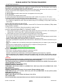
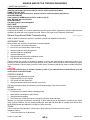
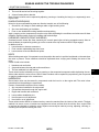
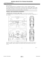
BODY INTERIOR
SECTION
INT
INTERIOR
A
B
C
D
E
CONTENTS
SYMPTOM DIAGNOSIS ............................... 2
Commercial Service Tool ......................................... 9
SQUEAK AND RATTLE TROUBLE DIAGNOSES ................................................................ 2
ON-VEHICLE REPAIR ................................. 10
Work Flow ................................................................. 2
Generic Squeak and Rattle Troubleshooting ............ 4
Diagnostic Worksheet ............................................... 6
PRECAUTION ............................................... 8
PRECAUTIONS ................................................... 8
Precaution for Supplemental Restraint System
(SRS) "AIR BAG" and "SEAT BELT PRE-TENSIONER" ................................................................... 8
Service Notice ........................................................... 8
PREPARATION ............................................ 9
DOOR FINISHER .............................................. 10
F
G
Removal and Installation .........................................10
BODY SIDE TRIM ............................................. 13
H
Removal and Installation .........................................13
FLOOR TRIM .................................................... 15
Removal and Installation .........................................15
I
HEADLINING .................................................... 16
Removal and Installation .........................................16
INT
LUGGAGE FLOOR TRIM ................................. 18
Removal and Installation .........................................18
K
PREPARATION ................................................... 9
BACK DOOR TRIM ........................................... 20
Special Service Tool ................................................. 9
Removal and Installation .........................................20
L
M
N
O
P
Revision: October 2008
INT-1
2009 Armada
SQUEAK AND RATTLE TROUBLE DIAGNOSES
< SYMPTOM DIAGNOSIS >
SYMPTOM DIAGNOSIS
SQUEAK AND RATTLE TROUBLE DIAGNOSES
Work Flow
INFOID:0000000003708201
SBT842
CUSTOMER INTERVIEW
Interview the customer if possible, to determine the conditions that exist when the noise occurs. Use the Diagnostic Worksheet during the interview to document the facts and conditions when the noise occurs and any
customer's comments; refer to INT-6, "Diagnostic Worksheet". This information is necessary to duplicate the
conditions that exist when the noise occurs.
• The customer may not be able to provide a detailed description or the location of the noise. Attempt to obtain
all the facts and conditions that exist when the noise occurs (or does not occur).
• If there is more than one noise in the vehicle, be sure to diagnose and repair the noise that the customer is
concerned about. This can be accomplished by test driving the vehicle with the customer.
• After identifying the type of noise, isolate the noise in terms of its characteristics. The noise characteristics
are provided so the customer, service adviser and technician are all speaking the same language when
defining the noise.
• Squeak —(Like tennis shoes on a clean floor)
Squeak characteristics include the light contact/fast movement/brought on by road conditions/hard surfaces
= higher pitch noise/softer surfaces = lower pitch noises/edge to surface = chirping.
• Creak—(Like walking on an old wooden floor)
Creak characteristics include firm contact/slow movement/twisting with a rotational movement/pitch dependent on materials/often brought on by activity.
• Rattle—(Like shaking a baby rattle)
Rattle characteristics include the fast repeated contact/vibration or similar movement/loose parts/missing
clip or fastener/incorrect clearance.
• Knock —(Like a knock on a door)
Knock characteristics include hollow sounding/sometimes repeating/often brought on by driver action.
• Tick—(Like a clock second hand)
Tick characteristics include gentle contacting of light materials/loose components/can be caused by driver
action or road conditions.
• Thump—(Heavy, muffled knock noise)
Thump characteristics include softer knock/dead sound often brought on by activity.
• Buzz—(Like a bumble bee)
Buzz characteristics include high frequency rattle/firm contact.
• Often the degree of acceptable noise level will vary depending upon the person. A noise that you may judge
as acceptable may be very irritating to the customer.
• Weather conditions, especially humidity and temperature, may have a great effect on noise level.
DUPLICATE THE NOISE AND TEST DRIVE
Revision: October 2008
INT-2
2009 Armada
SQUEAK AND RATTLE TROUBLE DIAGNOSES
< SYMPTOM DIAGNOSIS >
If possible, drive the vehicle with the customer until the noise is duplicated. Note any additional information on
the Diagnostic Worksheet regarding the conditions or location of the noise. This information can be used to
duplicate the same conditions when you confirm the repair.
If the noise can be duplicated easily during the test drive, to help identify the source of the noise, try to duplicate the noise with the vehicle stopped by doing one or all of the following:
1) Close a door.
2) Tap or push/pull around the area where the noise appears to be coming from.
3) Rev the engine.
4) Use a floor jack to recreate vehicle “twist”.
5) At idle, apply engine load (electrical load, half-clutch on M/T model, drive position on A/T model).
6) Raise the vehicle on a hoist and hit a tire with a rubber hammer.
• Drive the vehicle and attempt to duplicate the conditions the customer states exist when the noise occurs.
• If it is difficult to duplicate the noise, drive the vehicle slowly on an undulating or rough road to stress the
vehicle body.
CHECK RELATED SERVICE BULLETINS
After verifying the customer concern or symptom, check ASIST for Technical Service Bulletins (TSBs) related
to that concern or symptom.
If a TSB relates to the symptom, follow the procedure to repair the noise.
LOCATE THE NOISE AND IDENTIFY THE ROOT CAUSE
A
B
C
D
E
F
1.
Narrow down the noise to a general area.To help pinpoint the source of the noise, use a listening tool
(Chassis Ear: J-39570, Engine Ear: J-39565 and mechanic's stethoscope).
G
2. Narrow down the noise to a more specific area and identify the cause of the noise by:
• removing the components in the area that you suspect the noise is coming from.
Do not use too much force when removing clips and fasteners, otherwise clips and fasteners can be broken H
or lost during the repair, resulting in the creation of new noise.
• tapping or pushing/pulling the component that you suspect is causing the noise.
Do not tap or push/pull the component with excessive force, otherwise the noise will be eliminated only temI
porarily.
• feeling for a vibration with your hand by touching the component(s) that you suspect is (are) causing the
noise.
INT
• placing a piece of paper between components that you suspect are causing the noise.
• looking for loose components and contact marks.
Refer to INT-4, "Generic Squeak and Rattle Troubleshooting" .
K
REPAIR THE CAUSE
•
•
-
If the cause is a loose component, tighten the component securely.
If the cause is insufficient clearance between components:
separate components by repositioning or loosening and retightening the component, if possible.
insulate components with a suitable insulator such as urethane pads, foam blocks, felt cloth tape or urethane
tape. A NISSAN Squeak and Rattle Kit (J-43980) is available through your authorized NISSAN Parts Department.
CAUTION:
Do not use excessive force as many components are constructed of plastic and may be damaged.
Always check with the Parts Department for the latest parts information.
The following materials are contained in the NISSAN Squeak and Rattle Kit (J-43980). Each item can be
ordered separately as needed.
URETHANE PADS [1.5 mm (0.059 in) thick]
Insulates connectors, harness, etc.
76268-9E005: 100×135 mm (3.94×5.31 in)/76884-71L01: 60×85 mm (2.36×3.35 in)/76884-71L02: 15×25
mm (0.59×0.98 in)
INSULATOR (Foam blocks)
Insulates components from contact. Can be used to fill space behind a panel.
73982-9E000: 45 mm (1.77 in) thick, 50×50 mm (1.97×1.97 in)/73982-50Y00: 10 mm (0.39 in) thick,
50×50 mm (1.97×1.97 in)
INSULATOR (Light foam block)
80845-71L00: 30 mm (1.18 in) thick, 30×50 mm (1.18×1.97 in)
FELT CLOTH TAPE
Used to insulate where movement does not occur. Ideal for instrument panel applications.
Revision: October 2008
INT-3
2009 Armada
L
M
N
O
P
SQUEAK AND RATTLE TROUBLE DIAGNOSES
< SYMPTOM DIAGNOSIS >
68370-4B000: 15×25 mm (0.59×0.98 in) pad/68239-13E00: 5 mm (0.20 in) wide tape roll. The following
materials not found in the kit can also be used to repair squeaks and rattles.
UHMW (TEFLON) TAPE
Insulates where slight movement is present. Ideal for instrument panel applications.
SILICONE GREASE
Used instead of UHMW tape that will be visible or not fit.
Note: Will only last a few months.
SILICONE SPRAY
Use when grease cannot be applied.
DUCT TAPE
Use to eliminate movement.
CONFIRM THE REPAIR
Confirm that the cause of a noise is repaired by test driving the vehicle. Operate the vehicle under the same
conditions as when the noise originally occurred. Refer to the notes on the Diagnostic Worksheet.
Generic Squeak and Rattle Troubleshooting
INFOID:0000000003708202
Refer to Table of Contents for specific component removal and installation information.
INSTRUMENT PANEL
Most incidents are caused by contact and movement between:
1. The cluster lid A and instrument panel
2. Acrylic lens and combination meter housing
3. Instrument panel to front pillar garnish
4. Instrument panel to windshield
5. Instrument panel pins
6. Wiring harnesses behind the combination meter
7. A/C defroster duct and duct joint
These incidents can usually be located by tapping or moving the components to duplicate the noise or by
pressing on the components while driving to stop the noise. Most of these incidents can be repaired by applying felt cloth tape or silicone spray (in hard to reach areas). Urethane pads can be used to insulate wiring harness.
CAUTION:
Do not use silicone spray to isolate a squeak or rattle. If you saturate the area with silicone, you will
not be able to recheck the repair.
CENTER CONSOLE
Components to pay attention to include:
1. Shifter assembly cover to finisher
2. A/C control unit and cluster lid C
3. Wiring harnesses behind audio and A/C control unit
The instrument panel repair and isolation procedures also apply to the center console.
DOORS
Pay attention to the:
1. Finisher and inner panel making a slapping noise
2. Inside handle escutcheon to door finisher
3. Wiring harnesses tapping
4. Door striker out of alignment causing a popping noise on starts and stops
Tapping or moving the components or pressing on them while driving to duplicate the conditions can isolate
many of these incidents. You can usually insulate the areas with felt cloth tape or insulator foam blocks from
the NISSAN Squeak and Rattle Kit (J-43980) to repair the noise.
TRUNK
Trunk noises are often caused by a loose jack or loose items put into the trunk by the owner.
In addition look for:
1. Trunk lid bumpers out of adjustment
Revision: October 2008
INT-4
2009 Armada
SQUEAK AND RATTLE TROUBLE DIAGNOSES
< SYMPTOM DIAGNOSIS >
2. Trunk lid striker out of adjustment
3. The trunk lid torsion bars knocking together
4. A loose license plate or bracket
Most of these incidents can be repaired by adjusting, securing or insulating the item(s) or component(s) causing the noise.
A
B
SUNROOF/HEADLINING
Noises in the sunroof/headlining area can often be traced to one of the following:
1. Sunroof lid, rail, linkage or seals making a rattle or light knocking noise
2. Sun visor shaft shaking in the holder
3. Front or rear windshield touching headliner and squeaking
Again, pressing on the components to stop the noise while duplicating the conditions can isolate most of these
incidents. Repairs usually consist of insulating with felt cloth tape.
C
D
E
OVERHEAD CONSOLE (FRONT AND REAR)
Overhead console noises are often caused by the console panel clips not being engaged correctly. Most of
these incidents are repaired by pushing up on the console at the clip locations until the clips engage.
In addition look for:
1. Loose harness or harness connectors.
2. Front console map/reading lamp lens loose.
3. Loose screws at console attachment points.
F
G
SEATS
When isolating seat noise it's important to note the position the seat is in and the load placed on the seat when
H
the noise is present. These conditions should be duplicated when verifying and isolating the cause of the
noise.
Cause of seat noise include:
I
1. Headrest rods and holder
2. A squeak between the seat pad cushion and frame
3. The rear seatback lock and bracket
INT
These noises can be isolated by moving or pressing on the suspected components while duplicating the conditions under which the noise occurs. Most of these incidents can be repaired by repositioning the component
or applying urethane tape to the contact area.
K
UNDERHOOD
Some interior noise may be caused by components under the hood or on the engine wall. The noise is then
transmitted into the passenger compartment.
Causes of transmitted underhood noise include:
1. Any component installed to the engine wall
2. Components that pass through the engine wall
3. Engine wall mounts and connectors
4. Loose radiator installation pins
5. Hood bumpers out of adjustment
6. Hood striker out of adjustment
These noises can be difficult to isolate since they cannot be reached from the interior of the vehicle. The best
method is to secure, move or insulate one component at a time and test drive the vehicle. Also, engine RPM
or load can be changed to isolate the noise. Repairs can usually be made by moving, adjusting, securing, or
insulating the component causing the noise.
L
M
N
O
P
Revision: October 2008
INT-5
2009 Armada
SQUEAK AND RATTLE TROUBLE DIAGNOSES
< SYMPTOM DIAGNOSIS >
Diagnostic Worksheet
INFOID:0000000003708203
LAIA0072E
Revision: October 2008
INT-6
2009 Armada
SQUEAK AND RATTLE TROUBLE DIAGNOSES
< SYMPTOM DIAGNOSIS >
A
B
C
D
E
F
G
H
I
INT
K
L
M
N
O
LAIA0071E
P
Revision: October 2008
INT-7
2009 Armada
PRECAUTIONS
< PRECAUTION >
PRECAUTION
PRECAUTIONS
Precaution for Supplemental Restraint System (SRS) "AIR BAG" and "SEAT BELT
PRE-TENSIONER"
INFOID:0000000003708204
The Supplemental Restraint System such as “AIR BAG” and “SEAT BELT PRE-TENSIONER”, used along
with a front seat belt, helps to reduce the risk or severity of injury to the driver and front passenger for certain
types of collision. This system includes seat belt switch inputs and dual stage front air bag modules. The SRS
system uses the seat belt switches to determine the front air bag deployment, and may only deploy one front
air bag, depending on the severity of a collision and whether the front occupants are belted or unbelted.
Information necessary to service the system safely is included in the SR and SB section of this Service Manual.
WARNING:
• To avoid rendering the SRS inoperative, which could increase the risk of personal injury or death in
the event of a collision which would result in air bag inflation, all maintenance must be performed by
an authorized NISSAN/INFINITI dealer.
• Improper maintenance, including incorrect removal and installation of the SRS, can lead to personal
injury caused by unintentional activation of the system. For removal of Spiral Cable and Air Bag
Module, see the SR section.
• Do not use electrical test equipment on any circuit related to the SRS unless instructed to in this
Service Manual. SRS wiring harnesses can be identified by yellow and/or orange harnesses or harness connectors.
Service Notice
INFOID:0000000003708205
• When removing or installing various parts, place a cloth or padding on the vehicle body to prevent scratches.
• Handle trim, molding, instruments, grille, etc. carefully during removing or installing. Be careful not to soil or
damage them.
• Apply sealing compound where necessary when installing parts.
• When applying sealing compound, be careful that the sealing compound does not protrude from parts.
• When replacing any metal parts (for example body outer panel, members, etc.), be sure to take rust prevention measures.
Revision: October 2008
INT-8
2009 Armada
PREPARATION
< PREPARATION >
PREPARATION
A
PREPARATION
Special Service Tool
INFOID:0000000003708206
B
The actual shapes of Kent-Moore tools may differ from those of special service tools illustrated here.
C
Tool number
(Kent-Moore No.)
Tool name
Description
D
Locating the noise
—
(J-39570)
Chassis ear
E
F
G
SBT839
Repairing the cause of noise
—
(J-43980)
NISSAN Squeak and Rattle kit
H
I
INT
SBT840
Commercial Service Tool
INFOID:0000000003708207
(Kent-Moore No.)
Tool name
L
Description
(J-39565)
Engine ear
K
Locating the noise
M
N
SIIA0995E
O
P
Revision: October 2008
INT-9
2009 Armada
DOOR FINISHER
< ON-VEHICLE REPAIR >
ON-VEHICLE REPAIR
DOOR FINISHER
Removal and Installation
INFOID:0000000003708208
FRONT DOOR
AWJIA0006ZZ
1.
Power window switch assembly
2.
Front door finisher (LH shown)
3.
Pull handle cover
4.
Cap
5.
Inside door handle escutcheon
6.
Door lock knob
7.
Step lamp
8.
Seat memory switch (if equipped)
9.
Inside door handle assembly
Removal
1.
2.
3.
4.
5.
6.
Disconnect the battery negative terminal.
Remove the power window switch assembly.
• Disconnect the harness connectors.
Remove the cap from the pull handle cover and remove screw.
Remove the pull handle cover.
• Remove the screws behind pull handle cover.
Remove the seat memory switch (if equipped).
• Disconnect the harness connector.
Remove the step lamp.
Revision: October 2008
INT-10
2009 Armada
DOOR FINISHER
< ON-VEHICLE REPAIR >
• Disconnect the harness connector.
7. Remove the door finisher and disconnect the lock cable and handle cable from the inside door handle
assembly. Refer to INT-10, "Removal and Installation".
8. Remove the inside door handle assembly.
9. Remove door lock knob.
Installation
Installation is in the reverse order of removal.
A
B
C
REAR DOOR
D
E
F
G
H
I
INT
K
L
M
AWJIA0005ZZ
1.
Rear door tweeter
2.
Power window switch assembly
3.
4.
Pull handle cover
5.
Cap
6.
Inside door handle escutcheon
7.
Door lock knob
8.
Step lamp
9.
Inside door handle assembly
N
Rear door finisher LH
O
Removal
1.
2.
3.
4.
5.
P
Disconnect the battery negative terminal.
Remove the power window switch assembly.
• Disconnect the harness connector.
Remove the pull handle cover.
• Remove the screws behind the pull handle cover.
Remove the cap from the inside door handle escutcheon and the remove screw.
Remove the inside door handle escutcheon.
Revision: October 2008
INT-11
2009 Armada
DOOR FINISHER
< ON-VEHICLE REPAIR >
• Remove the screw behind inside door handle escutcheon.
6. Remove step lamp.
• Disconnect the step lamp harness connector.
7. Remove the door finisher and disconnect lock cable and handle cable from inside door handle assembly.
Refer to INT-10, "Removal and Installation".
8. Remove the inside door handle assembly.
9. Remove door lock knob.
10. Remove the rear door tweeter.
Installation
Installation is in the reverse order of removal.
Revision: October 2008
INT-12
2009 Armada
BODY SIDE TRIM
< ON-VEHICLE REPAIR >
BODY SIDE TRIM
A
Removal and Installation
INFOID:0000000003708209
CAUTION:
• Wrap the tip of flat-bladed screwdriver with a cloth when removing metal clips from finishers.
• When removing or installing body side welts, do not allow butyl seal to come in contact with pillar
finisher.
B
C
D
E
F
G
H
I
INT
K
L
M
N
WIIA0980E
1.
Center pillar upper finisher
2.
Center pillar assist grip
3.
Rear door welt
4.
Rear door parting seal
5.
Rear kicking plate
6.
Center pillar lower finisher
7.
Front kicking plate
8.
Lower dash side finisher
9.
Front door parting seal
11.
Front pillar assist grip
12.
Front pillar finisher
10. Front door welt
A.
P
Clip C103
LOWER DASH SIDE FINISHER
Removal
1.
Remove push pin from lower dash side finisher.
Revision: October 2008
INT-13
O
2009 Armada
BODY SIDE TRIM
< ON-VEHICLE REPAIR >
2. Remove front kicking plate from center pillar lower finisher.
3. Remove lower dash side finisher and front kicking plate together.
4. Remove lower dash side finisher from front kicking plate.
Installation
Installation is in the reverse order of removal.
CENTER PILLAR LOWER FINISHER
Removal
CAUTION:
Disconnect both terminals from battery in advance.
1. Disconnect the battery negative cable.
2. Remove seat belt anchor. Refer to SB-14, "Removal and Installation".
• On RH side, disconnect seat belt tension sensor.
3. Remove front and rear kicking plates.
4. Remove center pillar lower finisher.
Installation
Installation is in the reverse order of removal.
CENTER PILLAR UPPER FINISHER
Removal
1.
2.
3.
4.
5.
6.
Remove front and rear door welts.
Remove seat belt shoulder anchor and D-ring. Refer to SB-4, "Removal and Installation of Front Seat
Belt".
Remove front and rear kicking plates.
Remove center pillar lower finisher.
Remove center pillar assist grip.
Remove center pillar upper finisher.
Installation
Installation is in the reverse order of removal.
FRONT PILLAR FINISHER
Removal
1.
2.
Remove front pillar assist grip.
Remove front pillar finisher.
Installation
Installation is in the reverse order of removal.
KICKING PLATES
Removal
Release clips and remove front and/or rear kicking plates.
Installation
Installation is in the reverse order of removal.
DOOR PARTING SEALS
Removal
1.
2.
Open front and/or rear doors fully.
Release clips and remove parting seals.
Installation
Installation is in the reverse order of removal.
Revision: October 2008
INT-14
2009 Armada
FLOOR TRIM
< ON-VEHICLE REPAIR >
FLOOR TRIM
A
Removal and Installation
INFOID:0000000003708210
B
C
D
E
F
G
H
I
INT
AWJIA0408ZZ
1.
Carpet
2.
K
Floor mat hooks
REMOVAL
1.
2.
3.
4.
5.
6.
7.
8.
9.
10.
Disconnect the battery negative terminal
Remove front seats. Refer to SE-51, "Removal and Installation".
Remove lower seat belt anchors. Refer to SB-14, "Removal and Installation".
Remove lower body side trim. Refer to INT-13, "Removal and Installation".
Remove luggage lower side finishers (left / right). Refer to INT-18, "Removal and Installation".
Remove center console. Refer to IP-19, "Removal and Installation".
Remove rear lower finisher. Refer to INT-18, "Removal and Installation".
Remove floor mat hook.
Remove carpet.
Remove spare tire cover.
L
M
N
O
INSTALLATION
Installation is in the reverse order of removal.
Revision: October 2008
P
INT-15
2009 Armada
HEADLINING
< ON-VEHICLE REPAIR >
HEADLINING
Removal and Installation
INFOID:0000000003708211
AWJIA0007ZZ
1.
Headlining (without sunroof)
2.
Assist grip bracket
3.
4.
Sunvisor assembly LH
5.
Sunvisor holder RH
6.
Sunvisor holder LH
7.
Front roof console
8.
Sunglass bin
9.
Sunroof welt
Revision: October 2008
INT-16
Assist grip
2009 Armada
HEADLINING
< ON-VEHICLE REPAIR >
10.
Cap RH/LH
11.
13.
Rear storage bin or DVD display
14. Rear air control
Sunvisor assembly RH
15. Rear audio control assembly
12. Rear roof console bracket
16.
Rear roof console
17. Rear roof console finisher
18. Rear storage bin
19.
Air vent
20. Lamp assembly
21. Plastic clip
22.
Headlining (with sunroof)
23. Rear lamp lens
24. Rear lamp
25.
Rear roof finisher
26. Plastic clips
27. Metal clip
⇐
Vehicle front
A
B
C
REMOVAL
CAUTION:
Disconnect both terminals from battery in advance.
1. Disconnect the battery negative terminal.
2. Remove the body side trim. Refer to INT-13.
3. Remove the luggage floor trim. Refer to INT-18.
4. Remove the sunvisor assemblies.
5. Remove the sunvisor clips.
6. Remove the sunroof welt (if equipped).
7. Remove the front roof console.
• Disconnect the harnesses.
8. Remove the rear roof console.
• Disconnect the harnesses.
9. Remove the assist grips.
10. Remove the lamp assembly from the rear roof finisher.
• Disconnect the harness.
11. Remove the rear roof finisher.
12. Remove the headlining.
• Remove the clips from rear of headlining.
• Disconnect the harnesses.
13. Remove the rear air control.
• Disconnect the harness.
14. Remove the rear audio control assembly.
• Disconnect the harness.
15. Remove the lamp assemblies.
• Disconnect the harnesses.
16. Remove the air vents.
17. Remove the front roof console bracket.
18. Remove the rear roof console front bracket.
19. Remove the assist grip brackets from roof.
D
E
F
G
H
I
INT
K
L
M
INSTALLATION
Installation is in the reverse order of removal.
N
O
P
Revision: October 2008
INT-17
2009 Armada
LUGGAGE FLOOR TRIM
< ON-VEHICLE REPAIR >
LUGGAGE FLOOR TRIM
Removal and Installation
INFOID:0000000003708212
WIIA0970E
1.
Rear lower finisher cap
2.
Rear lower finisher
3.
Cap upper seat belt finisher RH
4.
Luggage side finisher RH
5.
Metal clip
6.
Plastic clip
7.
Luggage side finisher lower RH
8.
Luggage floor board
9.
Latch luggage floor board
Revision: October 2008
INT-18
2009 Armada
LUGGAGE FLOOR TRIM
< ON-VEHICLE REPAIR >
10. Leak check cap
11. Cup holder
12. Tie down hook
13. Floor side finisher RH
14. Power point assembly
15. Cargo net hook
16. Rear luggage box bracket
17. Front luggage floor bracket
18. Storage box
19. Floor side finisher LH
20. Luggage side finisher upper LH
21. Luggage side finisher lower LH
22. Lid luggage side lower
23. Coat hook
24. Cap lower seat belt finisher
25. Back door open/close switch
26. Cap luggage side upper
27. Cap upper seat belt finisher LH
A
C
REMOVAL
1.
2.
3.
4.
5.
6.
7.
8.
9.
10.
11.
12.
13.
14.
15.
16.
17.
18.
19.
B
Remove 2nd and 3rd row seat belts. Refer to SB-4, "Removal and Installation of Front Seat Belt", and SB9, "Removal and Installation of Third Row Seat Belt".
D
Remove third row seat belt buckles.
Remove third row seat assembly. Refer to SE-62, "Exploded View".
Remove back door weatherstrip. Refer to INT-20, "Removal and Installation".
E
Remove rear luggage room lamp. Refer to INT-16.
• Disconnect harness from lamp.
Remove rear upper finisher. Refer to INT-16.
F
Remove rear door kicking plates. Refer to INT-13.
Remove rear lower finisher.
G
Disconnect door open/close link. Refer to INT-20, "Removal and Installation".
Remove cargo net hooks.
Remove luggage side lower finishers LH/RH.
H
• Disconnect power point, RH side.
Remove coat hooks.
Remove luggage side upper finishers LH/RH.
I
• Disconnect harness to door open/close switch, LH side.
Remove tie down hooks LH/RH.
Remove floor side finishers LH/RH.
INT
Remove luggage floor board.
Remove storage box.
Remove front luggage floor bracket.
K
Remove rear luggage box bracket.
INSTALLATION
L
Installation is in the reverse order of removal.
M
N
O
P
Revision: October 2008
INT-19
2009 Armada
BACK DOOR TRIM
< ON-VEHICLE REPAIR >
BACK DOOR TRIM
Removal and Installation
INFOID:0000000003708213
WIIA0971E
1.
Back door upper finisher
2.
Back door glass weatherstrip
3.
Back door side finisher RH
4.
Back door lower finisher
5.
Back door bumper
6.
Back door pull handle
7.
Back door mask
8.
Back door side finisher LH
REMOVAL
1.
2.
3.
4.
5.
6.
7.
Disconnect door open/close link. Refer to DLK-237, "Door Lock Assembly".
Open back door glass.
Remove inside weatherstrip around back door glass.
Remove assist handle.
Release clips and remove back door lower finisher.
Release clips and remove back door upper finisher.
Release clips and remove back door side finishers LH and RH.
INSTALLATION
Installation is in the reverse order of removal.
Revision: October 2008
INT-20
2009 Armada