1
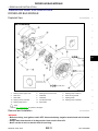
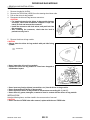
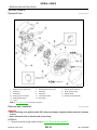
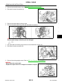
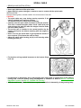
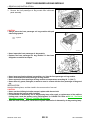
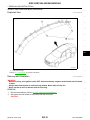
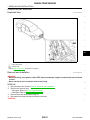
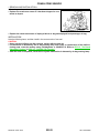
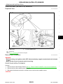
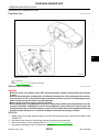
RESTRAINTS
SECTION
SR
SRS AIRBAG
A
B
C
D
E
CONTENTS
PRECAUTION ............................................... 2
PRECAUTIONS ................................................... 2
Exploded View .........................................................11
Removal and Installation .........................................11
Precaution for Supplemental Restraint System
(SRS) "AIR BAG" and "SEAT BELT PRE-TENSIONER" ................................................................... 2
Precaution Necessary for Steering Wheel Rotation after Battery Disconnect ..................................... 2
Occupant Classification System .............................. 3
Service ...................................................................... 3
SPIRAL CABLE ................................................ 14
PREPARATION ............................................ 4
SIDE CURTAIN AIR BAG MODULE ................ 19
Exploded View .........................................................14
Removal and Installation .........................................14
Exploded View .........................................................17
Removal and Installation .........................................17
J
CRASH ZONE SENSOR ................................... 21
BASIC INSPECTION .................................... 5
Exploded View .........................................................21
Removal and Installation .........................................21
FOR SIDE AND ROLLOVER COLLISION .................. 7
FOR SIDE AND ROLLOVER COLLISION : When
SRS is activated in a collision ................................... 7
FOR SIDE AND ROLLOVER COLLISION : When
SRS is not activated in a collision ............................. 8
I
Exploded View .........................................................19
Removal and Installation .........................................19
Commercial Service Tools ........................................ 4
FOR FRONTAL COLLISION ....................................... 5
FOR FRONTAL COLLISION : When SRS is activated in a collision ..................................................... 5
FOR FRONTAL COLLISION : When SRS is not
activated in a collision ............................................... 6
G
FRONT PASSENGER AIR BAG MODULE ...... 17 SR
PREPARATION ................................................... 4
COLLISION DIAGNOSIS .................................... 5
F
K
SIDE AIR BAG (SATELLITE) SENSOR ........... 23
Exploded View .........................................................23
Removal and Installation .........................................23
L
DIAGNOSIS SENSOR UNIT ............................. 25
Exploded View .........................................................25
Removal and Installation .........................................25
M
SEAT BELT PRE-TENSIONER ........................ 27
Exploded View .........................................................27
Removal and Installation .........................................27
N
REMOVAL AND INSTALLATION ............... 11
OCCUPANT CLASSIFICATION SYSTEM
CONTROL UNIT ................................................ 28
O
DRIVER AIR BAG MODULE ..............................11
Exploded View .........................................................28
Removal and Installation .........................................28
P
Revision: 2010 June
SR-1
2011 M37/M56
PRECAUTIONS
< PRECAUTION >
PRECAUTION
PRECAUTIONS
Precaution for Supplemental Restraint System (SRS) "AIR BAG" and "SEAT BELT
PRE-TENSIONER"
INFOID:0000000006059153
The Supplemental Restraint System such as “AIR BAG” and “SEAT BELT PRE-TENSIONER”, used along
with a front seat belt, helps to reduce the risk or severity of injury to the driver and front passenger for certain
types of collision. This system includes seat belt switch inputs and dual stage front air bag modules. The SRS
system uses the seat belt switches to determine the front air bag deployment, and may only deploy one front
air bag, depending on the severity of a collision and whether the front occupants are belted or unbelted.
Information necessary to service the system safely is included in the “SRS AIR BAG” and “SEAT BELT” of this
Service Manual.
WARNING:
• To avoid rendering the SRS inoperative, which could increase the risk of personal injury or death in
the event of a collision that would result in air bag inflation, all maintenance must be performed by
an authorized NISSAN/INFINITI dealer.
• Improper maintenance, including incorrect removal and installation of the SRS, can lead to personal
injury caused by unintentional activation of the system. For removal of Spiral Cable and Air Bag
Module, see the “SRS AIR BAG”.
• Do not use electrical test equipment on any circuit related to the SRS unless instructed to in this
Service Manual. SRS wiring harnesses can be identified by yellow and/or orange harnesses or harness connectors.
PRECAUTIONS WHEN USING POWER TOOLS (AIR OR ELECTRIC) AND HAMMERS
WARNING:
• When working near the Air Bag Diagnosis Sensor Unit or other Air Bag System sensors with the
ignition ON or engine running, DO NOT use air or electric power tools or strike near the sensor(s)
with a hammer. Heavy vibration could activate the sensor(s) and deploy the air bag(s), possibly
causing serious injury.
• When using air or electric power tools or hammers, always switch the ignition OFF, disconnect the
battery, and wait at least 3 minutes before performing any service.
Precaution Necessary for Steering Wheel Rotation after Battery Disconnect
INFOID:0000000006059154
NOTE:
• Before removing and installing any control units, first turn the push-button ignition switch to the LOCK position, then disconnect both battery cables.
• After finishing work, confirm that all control unit connectors are connected properly, then re-connect both
battery cables.
• Always use CONSULT-III to perform self-diagnosis as a part of each function inspection after finishing work.
If a DTC is detected, perform trouble diagnosis according to self-diagnosis results.
For vehicle with steering lock unit, if the battery is disconnected or discharged, the steering wheel will lock and
cannot be turned.
If turning the steering wheel is required with the battery disconnected or discharged, follow the operation procedure below before starting the repair operation.
OPERATION PROCEDURE
1.
2.
3.
4.
Connect both battery cables.
NOTE:
Supply power using jumper cables if battery is discharged.
Turn the push-button ignition switch to ACC position.
(At this time, the steering lock will be released.)
Disconnect both battery cables. The steering lock will remain released with both battery cables disconnected and the steering wheel can be turned.
Perform the necessary repair operation.
Revision: 2010 June
SR-2
2011 M37/M56
PRECAUTIONS
< PRECAUTION >
5. When the repair work is completed, re-connect both battery cables. With the brake pedal released, turn
the push-button ignition switch from ACC position to ON position, then to LOCK position. (The steering
wheel will lock when the push-button ignition switch is turned to LOCK position.)
6. Perform self-diagnosis check of all control units using CONSULT-III.
A
Occupant Classification System
B
INFOID:0000000005850883
Replace occupant classification system control unit and passenger front seat cushion as an assembly.
Refer to SE-101, "Exploded View".
Service
C
INFOID:0000000005850884
D
• Never use electrical test equipment to check SRS circuits unless instructed to in this Service Manual.
• Before servicing the SRS, turn ignition switch OFF, disconnect battery negative terminal and wait at least 3
minutes.
For approximately 3 minutes after the cables are removed, it is still possible for the air bag and seat belt pre- E
tensioner to deploy. Therefore, never work on any SRS connectors or wires until at least 3 minutes have
elapsed.
• Diagnosis sensor unit must always be installed with their arrow marks “⇐” pointing towards the front of the
vehicle for proper operation. Also check diagnosis sensor unit for cracks, deformities or rust before installa- F
tion and replace as required.
• The spiral cable must be aligned in the neutral position since its rotations are limited. Never turn steering
wheel and column after removal of steering gear.
G
• Handle air bag module carefully. Always place driver and front passenger air bag modules with the pad side
facing upward and seat mounted front side air bag module standing with the stud bolt side facing down.
• Conduct self-diagnosis to check entire SRS for proper functioning after replacing any components.
SR
• After air bag inflates, the instrument panel assembly should be replaced if damaged.
I
J
K
L
M
N
O
P
Revision: 2010 June
SR-3
2011 M37/M56
PREPARATION
< PREPARATION >
PREPARATION
PREPARATION
Commercial Service Tools
INFOID:0000000005850885
Tool name
Description
Removes tool of driver air bag module and/or
Diagnosis sensor unit
Tamper resistant TORX bit
S-NT757
Remover tool
Removes clips, pawls, and metal clips
JMKIA3050ZZ
Revision: 2010 June
SR-4
2011 M37/M56
COLLISION DIAGNOSIS
< BASIC INSPECTION >
BASIC INSPECTION
A
COLLISION DIAGNOSIS
FOR FRONTAL COLLISION
B
FOR FRONTAL COLLISION : When SRS is activated in a collision
INFOID:0000000005850886
CAUTION:
Due to varying models and option levels, not all parts listed in the chart below apply to all vehicles.
C
WORK PROCEDURE
1.
2.
3.
4.
5.
6.
7.
Before performing any of the following steps, ensure that all vehicle body and structural repairs have been
completed.
Replace the diagnosis sensor unit.
Remove the front air bag modules, crash zone sensor, bracket and seat belt pre-tensioner assemblies.
Check the SRS components using the table below:
Replace any SRS components showing visible signs of damage. (dents, cracks and deformation, etc.)
Install new front air bag modules, crash zone sensor assembly, bracket and seat belt pre-tensioner
assemblies.
Perform self-diagnosis using CONSULT-III or air bag warning lamp. Refer to SRC-16, "CONSULT-III
Function" or SRC-12, "On Board Diagnosis Function" for details. Ensure entire SRS operates properly.
After the work is completed, perform self-diagnosis to check that no malfunction is detected. Refer to
SRC-12, "Description".
Inspection
Driver air bag module
If the driver air bag has deployed:
REPLACE
Install with new fasteners.
Front passenger air bag module
(if equipped)
If the front passenger air bag has deployed:
REPLACE
Install with new fasteners.
Crash zone sensor
If any of the front air bags or seat belt pre-tensioners* have been activated:
REPLACE the crash zone sensor and bracket with new fasteners.
*: Confirm seat belt pre-tensioner activation using CONSULT-III only.
Seat belt pre-tensioner assemblies
(All applicable locations: buckle,
retractor, lap outer)
If either the driver or passenger seat belt pre-tensioner* has been activated:
REPLACE all seat belt pre-tensioner assemblies with new fasteners.
*: Confirm seat belt pre-tensioner activation using CONSULT-III only.
Diagnosis sensor unit
If any of the SRS components have been activated:
REPLACE the diagnosis sensor unit.
Install with new fasteners.
1.
2.
Steering wheel
3.
4.
5.
6.
If the driver front air bag has deployed:
REPLACE the spiral cable.
Occupant classification system
(Passenger seat)
1.
2.
3.
4.
5.
6.
Revision: 2010 June
G
J
K
L
M
N
O
P
Remove passenger seat assembly.
Check control unit case for dents, cracks of deformities.
Check connectors and pressure sensor tube for damage, and terminals for deformities.
Check seat frame and cushion pan for dents or deformities.
If no damage is found, reinstall seat with new fasteners.
If damaged − REPLACE seat cushion assembly with new fasteners.
SR-5
F
I
Visually check steering wheel for deformities.
Check harness (built into steering wheel) and connectors for damage, and terminals for deformities.
Install driver air bag module into the steering wheel to check fit and alignment with the wheel.
Check steering wheel for excessive free play.
If no damage is found, reinstall.
If damaged − REPLACE.
Spiral cable
E
SR
SRS INSPECTION (FOR FRONTAL COLLISION)
Part
D
2011 M37/M56
COLLISION DIAGNOSIS
< BASIC INSPECTION >
Part
Harness and connectors
Instrument panel assembly
Inspection
1.
2.
3.
4.
Check connectors for poor connection, damage, and terminals for deformities.
Check harness for binding, chafing, cuts, or deformities.
If no damage is found, reinstall the harness and connectors.
If damaged − REPLACE the damaged harness. Do not attempt to repair, splice or modify any
SRS harness.
If the front passenger air bag has deployed:
REPLACE the instrument panel assembly. (integrated type)
FOR FRONTAL COLLISION : When SRS is not activated in a collision
INFOID:0000000005850887
CAUTION:
Due to varying models and option levels, not all parts listed in the chart below apply to all vehicles.
WORK PROCEDURE
1.
2.
3.
4.
Before performing any of the following steps, ensure that all vehicle body and structural repairs have been
completed.
Check the SRS components using the table below:
Replace any SRS components showing visible signs of damage. (dents, cracks and deformation, etc.)
Perform self-diagnosis using CONSULT-III or air bag warning lamp. Refer to SRC-16, "CONSULT-III
Function" or SRC-12, "On Board Diagnosis Function" for details. Ensure entire SRS operates properly.
After the work is completed, perform self-diagnosis to check that no malfunction is detected. Refer to
SRC-12, "Description".
SRS INSPECTION (FOR FRONTAL COLLISION)
Part
Inspection
Driver air bag module
If the driver air bag has NOT been deployed:
1.
Remove driver air bag module. Check harness cover and connectors for damage, terminals for
deformities, and harness for binding.
2.
Install driver air bag module into the steering wheel to check fit and alignment with the wheel.
3.
If no damage is found, reinstall with new fasteners.
4.
If damaged − REPLACE. Install driver air bag module with new fasteners.
Front passenger air bag module
(if equipped)
If the front passenger air bag has NOT been deployed:
1.
Remove front passenger air bag module. Check harness cover and connectors for damage, terminals for deformities, and harness for binding.
2.
Install front passenger air bag module into the instrument panel to check fit with the instrument
panel.
3.
If no damage is found, reinstall with new fasteners.
4.
If damaged − REPLACE. Install front passenger air bag modules with new fasteners.
Crash zone sensor
If the front air bags or seat belt pre-tensioners have NOT been activated:
1.
Remove the crash zone sensor. Check harness connectors for damage, terminals for deformities, and harness for binding.
2.
Check for visible signs of damage (dents, cracks, deformation, etc.) of the crash zone sensor
and bracket.
3.
Install the crash zone sensor to check fit.
4.
If no damage is found, reinstall with new fasteners.
5.
If damaged − REPLACE the crash zone sensor and bracket with new fasteners.
Seat belt pre-tensioner assemblies
(All applicable locations: buckle,
retractor, lap outer)
If the pre-tensioners have NOT been activated:
1.
Remove seat belt pre-tensioners.
Check harness cover and connectors for damage, terminals for deformities, and harness for
binding.
2.
Check belts for damage and anchors for loose mounting.
3.
Check retractor for smooth operation.
4.
Check seat belt adjuster for damage.
5.
Check for deformities of the center pillar inner.
6.
If the center pillar inner has no damage, REPLACE the seat belt pre-tensioner assembly.
7.
If no damage is found, reinstall seat belt pre-tensioner assembly.
8.
If damaged − REPLACE. Install the seat belt pre-tensioners with new fasteners.
Revision: 2010 June
SR-6
2011 M37/M56
COLLISION DIAGNOSIS
< BASIC INSPECTION >
Part
Diagnosis sensor unit
Inspection
1.
2.
Steering wheel
A
If none of the SRS components have been activated:
1.
Check case for dents, cracks or deformities.
2.
Check connectors for damage, and terminals for deformities.
3.
If no damage is found, reinstall with new fasteners.
4.
If damaged − REPLACE. Install diagnosis sensor unit with new fasteners.
3.
4.
5.
6.
B
Visually check steering wheel for deformities.
Check harness (built into steering wheel) and connectors for damage, and terminals for deformities.
Install driver air bag module into the steering wheel to check fit and alignment with the wheel.
Check steering wheel for excessive free play.
If no damage is found, reinstall.
If damaged − REPLACE.
Spiral cable
If the driver front air bag has not deployed:
1.
Visually check spiral cable and combination switch for damage.
2.
Check connectors and protective tape for damage.
3.
Check steering wheel for noise, binding or heavy operation.
4.
If no damage is found, reinstall.
5.
If damaged − REPLACE.
Occupant classification system
(Passenger seat)
1.
2.
3.
4.
5.
6.
Remove passenger seat assembly.
Check control unit case for dents, cracks of deformities.
Check connectors and pressure sensor tube for damage, and terminals for deformities.
Check seat frame and cushion pan for dents or deformities.
If no damage is found, reinstall seat with new fasteners.
If damaged − REPLACE seat cushion assembly with new fasteners.
1.
2.
3.
4.
Check connectors for poor connection, damage, and terminals for deformities.
Check harness for binding, chafing, cuts, or deformities.
If no damage is found, reinstall the harness and connectors.
If damaged − REPLACE the damaged harness. Do not attempt to repair, splice or modify any
SRS harness.
Harness and connectors
Instrument panel assembly
C
D
E
F
If the front passenger air bag has NOT deployed:
1.
Visually check instrument panel assembly for damage.
2.
If no damage is found, reinstall the instrument panel assembly.
3.
If damaged − REPLACE the instrument panel assembly.
G
SR
I
J
FOR SIDE AND ROLLOVER COLLISION
FOR SIDE AND ROLLOVER COLLISION : When SRS is activated in a collision
K
INFOID:0000000005850888
CAUTION:
Due to varying models and option levels, not all parts listed in the chart below apply to all vehicles.
WORK PROCEDURE
1.
2.
3.
4.
5.
Before performing any of the following steps, ensure that all vehicle body and structural repairs have been
completed.
Replace the following components:
• Front seat back assembly (on the side on which side air bag is activated)
• Door finisher (on the side on which door-mounted curtain air bag is activated)
• Pop-up roll bar assemblies and pop-up roll bar covers
• Side air bag (satellite) sensor LH/RH (on the side on which side air bag is activated)
• Diagnosis sensor unit
• Seat belt pre-tensioner assemblies
Check the SRS components and the related parts using the following table.
Replace any SRS components and the related parts showing visible signs of damage. (dents, cracks,
deformation, etc.)
Perform self-diagnosis using CONSULT-III and “AIR BAG” warning lamp. Refer to SRC-16, "CONSULT-III
Function" or SRC-12, "On Board Diagnosis Function" for details. Make sure entire SRS operates properly.
After the work is completed, perform self-diagnosis to check that no malfunction is detected. Refer to
SRC-12, "Description".
Revision: 2010 June
SR-7
2011 M37/M56
L
M
N
O
P
COLLISION DIAGNOSIS
< BASIC INSPECTION >
SRS INSPECTION (FOR SIDE AND ROLLOVER COLLISION)
Part
Inspection
Side curtain air bag module LH
If the side curtain air bag LH has deployed:
REPLACE the side curtain air bag module LH.
Install with new fasteners.
Side curtain air bag module RH
If the side curtain air bag RH has deployed:
REPLACE the side curtain air bag module RH.
Install with new fasteners.
Front side air bag module LH
If the front side air bag LH has deployed:
REPLACE front seatback assembly LH.
Front side air bag module RH
If the front side air bag RH has deployed:
REPLACE front seatback assembly RH.
Side air bag (satellite) sensor
(LH or RH)
If any of the SRS components have deployed:
REPLACE the side air bag (satellite) sensor on the collision side with new fasteners.
Diagnosis sensor unit
If any of the SRS components have deployed:
REPLACE the diagnosis sensor unit with new fasteners.
Seat belt pre-tensioner assemblies
(All applicable locations: buckle,
retractor, lap outer)
If either the driver or passenger seat belt pre-tensioner* has been activated:
REPLACE all seat belt pre-tensioner assemblies with new fasteners.
*: Confirm seat belt pre-tensioner activation using CONSULT-III only.
Center inner pillar
1.
2.
Check the center inner pillar on the collision side for damage (dents, cracks, deformation, etc.).
If damaged − REPAIR the center inner pillar.
1.
Check for visible signs of damage (dents, cracks, deformation, etc.) of the interior trim on the
collision side.
If damaged − REPLACE the damaged trim parts.
Trim/headlining
2.
Door-mounted curtain air bag
module LH
If the door-mounted curtain air bag module LH has deployed:
REPLACE the door finisher LH and door-mounted curtain air bag module.
Install with new fasteners.
Door-mounted curtain air bag
module RH
If the door-mounted curtain air bag module RH has deployed:
REPLACE the door finisher RH and door-mounted curtain air bag module.
Install with new fasteners.
Pop-up roll bar assemblies
If the pop-up roll bar has deployed:
REPLACE pop-up roll bar assemblies and pop-up roll bar covers.
Install with new fasteners.
FOR SIDE AND ROLLOVER COLLISION : When SRS is not activated in a collision
INFOID:0000000005850889
CAUTION:
Due to varying models and option levels, not all parts listed in the chart below apply to all vehicles.
WORK PROCEDURE
1.
2.
3.
4.
Before performing any of the following steps, ensure that all vehicle body and structural repairs have been
completed.
Check the SRS components and the related parts using the following table.
• If the front seat back assembly is damaged, the front seat back assembly must be replaced.
• If the door finisher assembly is damaged, the door finisher assembly and door-mounted curtain air bag
module must be replaced.
Perform self-diagnosis using CONSULT-III and “AIR BAG” warning lamp. Refer to SRC-16, "CONSULT-III
Function" or SRC-12, "On Board Diagnosis Function" for details. Make sure entire SRS operates properly.
After the work is completed, perform self-diagnosis to check that no malfunction is detected. Refer to
SRC-12, "Description".
SRS INSPECTION (FOR SIDE AND ROLLOVER COLLISION)
Revision: 2010 June
SR-8
2011 M37/M56
COLLISION DIAGNOSIS
< BASIC INSPECTION >
Part
Inspection
Side curtain air bag module LH
If the side curtain air bag LH has NOT deployed:
1.
Check for visible signs of damage (dents, tears, deformation, etc.) of the center pillar on the collision side.
2.
If damaged − Remove the side curtain air bag module LH.
3.
Check for visible signs of damage (tears etc.) of the side curtain air bag module LH.
4.
Check harness and connectors for damage, and terminals for deformities.
5.
If no damage is found, reinstall the side curtain air bag module LH with new fasteners.
6.
If damaged − REPLACE the side curtain air bag module LH with new fasteners.
Side curtain air bag module RH
If the side curtain air bag RH has NOT deployed:
1.
Check for visible signs of damage (dents, tears, deformation, etc.) of the center pillar on the collision side.
2.
If damaged − Remove the side curtain air bag module RH.
3.
Check for visible signs of damage (tears etc.) of the side curtain air bag module RH.
4.
Check harness and connectors for damage, and terminals for deformities.
5.
If no damage is found, reinstall the side curtain air bag module RH with new fasteners.
6.
If damaged − REPLACE the side curtain air bag module RH with new fasteners.
Front side air bag module LH
If the front side air bag LH has NOT deployed:
1.
Check for visible signs of damage (dents, tears, deformation, etc.) of the seat back on the collision side.
2.
Check harness and connectors for damage, and terminals for deformities.
3.
If damaged − REPLACE the front seatback assembly LH.
Front side air bag module RH
If the front side air bag RH has NOT deployed:
1.
Check for visible signs of damage (dents, tears, deformation, etc.) of the seat back on the collision side.
2.
Check harness and connectors for damage, and terminals for deformities.
3.
If damaged − REPLACE the front seatback assembly RH.
Side air bag (satellite) sensor
(LH or RH)
If none of the SRS components have been activated:
1.
Remove the side air bag (satellite) sensor (LH or RH) on the collision side. Check harness connectors for damage, terminals for deformities, and harness for binding.
2.
Check for visible signs of damage (dents, cracks, deformation, etc.) of the side air bag (satellite)
sensor (LH or RH).
3.
Install the side air bag (satellite) sensor (LH or RH) to check fit.
4.
If no damage is found, reinstall the side sir bag (satellite) sensor (LH or RH) with new fasteners.
5.
If damaged − REPLACE the side air bag (satellite) sensor (LH or RH) with new fasteners.
Diagnosis sensor unit
If none of the SRS components have been activated:
1.
Check case and bracket for dents, cracks or deformities.
2.
Check connectors for damage, and terminals for deformities.
3.
If no damage is found, reinstall the diagnosis sensor unit with new fasteners.
4.
If damaged − REPLACE the diagnosis sensor unit with new fasteners.
Seat belt pre-tensioner assemblies
(All applicable locations: buckle,
retractor, lap outer)
If the pre-tensioners have NOT been activated:
1.
Remove seat belt pre-tensioners.
Check harness cover and connectors for damage, terminals for deformities, and harness for
binding.
2.
Check belts for damage and anchors for loose mounting.
3.
Check retractor for smooth operation.
4.
Check seat belt adjuster for damage.
5.
Check for deformities of the center pillar inner.
6.
If the center pillar inner has no damage, REPLACE the seat belt pre-tensioner assembly.
7.
If no damage is found, reinstall seat belt pre-tensioner assembly.
8.
If damaged − REPLACE. Install the seat belt pre-tensioners with new fasteners.
Seat (with front side air bag)
If the front LH or front RH side air bag modules have NOT deployed:
1.
Visually check the seat on the collision side.
2.
Remove the seat on the collision side and check the following for damage and deformities.
Harness, connectors and terminals
Frame and recliner (for front and rear seat), and also adjuster and slides (for front seat)
3.
If no damage is found, reinstall the seat.
4.
If damaged − REPLACE the damaged seat parts using new fasteners. If the front seat back is
damaged, the front seat back assembly must be replaced.
Center inner pillar
1.
2.
Revision: 2010 June
B
C
D
E
F
G
SR
I
J
K
L
Check the center inner pillar on the collision side for damage (dents, cracks, deformation, etc.).
If damaged − REPAIR the center inner pillar.
SR-9
A
2011 M37/M56
M
N
O
P
COLLISION DIAGNOSIS
< BASIC INSPECTION >
Part
Inspection
1.
Trim/headlining
2.
Check for visible signs of damage (dents, cracks, deformation, etc.) of the interior trim on the
collision side.
If damaged − REPLACE the damaged trim parts.
Door-mounted curtain air bag
module LH
If the door-mounted curtain air bag LH has NOT deployed:
1.
Check for visible signs of damage (dents, tears, deformation, etc.) of the door finisher on the
collision side.
2.
If damaged − REPLACE the door finisher LH with new fasteners.
3.
Check for visible signs of damaged (tears etc.) of the door-mounted curtain air bag module LH.
4.
Check harness and connectors for damage, and terminals for deformities.
5.
If no damage is found, reinstall door finisher.
CAUTION:
When removing door-mounted curtain air bag module from door finisher, never reuse
door finisher.
6.
If damaged − REPLACE the door finisher LH and door-mounted curtain air bag module LH with
new fasteners.
Door-mounted curtain air bag
module RH
If the door-mounted curtain air bag RH has NOT deployed:
1.
Check for visible signs of damage (dents, tears, deformation, etc.) of the door finisher on the
collision side.
2.
If damaged − REPLACE the door finisher RH with new fasteners.
3.
Check for visible signs of damage (tears etc.) of the door-mounted curtain air bag module RH.
4.
Check harness and connectors for damage, and terminals for deformities.
5.
If no damage is found, reinstall door finisher.
CAUTION:
When removing door-mounted curtain air bag module from door finisher, never reuse
door finisher.
6.
If damaged − REPLACE the door finisher RH and door-mounted curtain air bag module RH with
new fasteners.
Pop-up roll bar
If the pop-up roll bar has NOT deployed:
1.
Check for visible signs of damage (dents, tears, deformation, etc.) of the pop-up roll bar.
2.
If damaged − REPLACE the pop-up roll bar with new fasteners.
3.
Check harness and connectors for damage, and terminals for deformities.
4.
If no damage is found, reinstall the pop-up roll bar with new fasteners.
5.
Check for visible signs of damage (dents, cracks, deformation, etc.) of the seatback support
brace assembly.
6.
If damaged − REPAIR the seatback support brace assembly.
Revision: 2010 June
SR-10
2011 M37/M56
DRIVER AIR BAG MODULE
< REMOVAL AND INSTALLATION >
REMOVAL AND INSTALLATION
A
DRIVER AIR BAG MODULE
Exploded View
INFOID:0000000005850890
B
C
D
E
F
G
SR
I
J
K
L
JMHIA1512GB
1.
Steering column upper cover
2.
Steering column lower cover
3.
Steering column mask LH
4.
Side lid LH
5.
TORX bolt
6.
Driver air bag module
7.
Side lid RH
8.
TORX bolt
9.
Steering wheel
10. Steering column mask RH
11. Combination switch
13. Steering angle sensor
14. Spiral cable
M
N
12. Steering column assembly
O
: Pawl
Refer to GI-4, "Components" for symbols in the figure.
P
Removal and Installation
INFOID:0000000005850891
WARNING:
• Before servicing, turn ignition switch OFF, disconnect battery negative terminal and wait 3 minutes
or more.
• Always work from the side of air bag module. Never work in front of it.
• Never use the air tools or electric tools for servicing.
Revision: 2010 June
SR-11
2011 M37/M56
DRIVER AIR BAG MODULE
< REMOVAL AND INSTALLATION >
REMOVAL
1. Remove the side lid (LH/RH).
2. Remove the TORX bolts (LH/RH) from the steering wheel lower side.
3. Pull out the driver air bag module.
4. Disconnect the driver air bag harness connectors.
CAUTION:
• For installing/removing the driver air bag module harness
connector, insert thin screwdriver wrapped in tape into
notch, lift lock and remove the connector.
• Install the connector with lock raised, and push lock into
the connector.
• After installing the connector, check that the lock is
pushed securely into it.
PHIA0953J
5. Remove the driver air bag module.
CAUTION:
• Always place the driver air bag module with pad side facing
upward.
: Vehicle front
JMHIA0539ZZ
• Never impact the driver air bag module.
• Replace the driver air bag module if it has been dropped or
sustained an impact.
JMHIA0009ZZ
•
•
•
•
Never insert any foreign objects (screwdriver, etc.) into the driver air bag module.
Never disassemble the driver air bag module.
Never expose the driver air bag module to temperatures exceeding 90 °C (194 °F).
Never allow oil, grease, detergent, or water to come in contact with the driver air bag module.
INSTALLATION
Note the following items, and then install in the reverse order of removal.
CAUTION:
• Never use the old TORX bolts after removal, replace with the new TORX bolts.
Revision: 2010 June
SR-12
2011 M37/M56
DRIVER AIR BAG MODULE
< REMOVAL AND INSTALLATION >
• Fix the driver air bag module harnesses to the harness fixing
hook (A).
A
B
C
JMHIA1513ZZ
D
• Never damage the harness while installing.
• Tighten the TORX bolts after completely adjusting the centers of fixing holes on the driver air bag
module side and the steering wheel side. If the holes are misaligned, the bolt threads are damaged
and the module is not installed securely.
• If malfunction is detected by the air bag warning lamp, after repair or replacement of the malfunctioning parts, reset the memory using self-diagnosis or CONSULT-III. Refer to SRC-12, "On Board
Diagnosis Function" or SRC-16, "CONSULT-III Function".
• After the work is complete, check that no system malfunction is detected by air bag warning lamp.
E
F
G
SR
I
J
K
L
M
N
O
P
Revision: 2010 June
SR-13
2011 M37/M56
SPIRAL CABLE
< REMOVAL AND INSTALLATION >
SPIRAL CABLE
Exploded View
INFOID:0000000005892122
JMHIA1512GB
1.
Steering column upper cover
2.
Steering column lower cover
3.
Steering column mask LH
4.
Side lid LH
5.
TORX bolt
6.
Driver air bag module
7.
Side lid RH
8.
TORX bolt
9.
Steering wheel
10. Steering column mask RH
11. Combination switch
13. Steering angle sensor
14. Spiral cable
12. Steering column assembly
: Pawl
Refer to GI-4, "Components" for symbols in the figure.
Removal and Installation
INFOID:0000000005850893
WARNING:
• Before servicing, turn ignition switch OFF, disconnect battery negative terminal and wait 3 minutes
or more.
• Never use the air tools or electric tools for servicing.
REMOVAL
1.
Remove the driver air bag module. Refer to SR-11, "Removal and Installation".
Revision: 2010 June
SR-14
2011 M37/M56
SPIRAL CABLE
< REMOVAL AND INSTALLATION >
2. Remove the steering wheel. Refer to ST-34, "Removal and Installation".
3. Remove the steering column cover. Refer to IP-13, "Removal and Installation".
4. Disconnect harness connectors (A).
A
B
C
D
JMHIA1514ZZ
5.
6.
E
Remove the spiral cable mounting screws.
Remove the spiral cable fixing pawls with flat-bladed screwdriver.
F
G
SR
JMHIA1516ZZ
CAUTION:
Remove pawls slowly so that they are not damaged.
I
: Pawl
7.
8.
J
Pull spiral cable and steering angle sensor as a set toward the vehicle rear.
Disconnect harness connector (A).
K
L
M
JMHIA1515ZZ
N
9. Remove the steering angle sensor. Refer to BRC-144, "Removal and Installation".
CAUTION:
• Never impact the spiral cable.
• Replace the spiral cable if it is dropped or sustains an impact.
O
P
JMHIA0009ZZ
Revision: 2010 June
SR-15
2011 M37/M56
SPIRAL CABLE
< REMOVAL AND INSTALLATION >
• Never disassemble the spiral cable.
• Never apply lubricant to the spiral cable.
• Never allow oil, grease, detergent, or water to come in contact with the spiral cable.
INSTALLATION
Note the following items, and then install in the reverse order of removal.
CAUTION:
• The spiral cable may snap during steering operation if the
cable is installed in an improper position.
The neutral position is set as per the following.
• Carefully turn the spiral cable clockwise to the end position.
Then turn it counterclockwise (about 2 and a half turns) and
stop turning at the mark (B) when the stopper insertion holes
are in the same position.
• The service part is installed in the neutral position by the
stopper and can be set without adjusting after the stopper is
removed.
• Never over turn the spiral cable or go beyond the number of
turns required. (This causes the cable to snap)
• Adjust the spiral cable locating pin (A) to the steering wheel
locating pin hole (C).
JMHIA0657ZZ
• Fix the driver air bag module harnesses to the harness fixing
hook (A).
JMHIA1513ZZ
• If malfunction is detected by the air bag warning lamp, after repair or replacement of the malfunctioning parts, reset the memory using self-diagnosis or CONSULT-III. Refer to SRC-12, "On Board
Diagnosis Function" or SRC-16, "CONSULT-III Function".
• After the work is completed, check that no system malfunction is detected by air bag warning lamp.
Revision: 2010 June
SR-16
2011 M37/M56
FRONT PASSENGER AIR BAG MODULE
< REMOVAL AND INSTALLATION >
FRONT PASSENGER AIR BAG MODULE
Exploded View
A
INFOID:0000000005850894
B
C
D
E
F
G
SR
I
J
K
L
JMHIA1517GB
1.
Instrument panel assembly
2.
Front passenger air bag module
M
Refer to GI-4, "Components" for symbols in the figure.
Removal and Installation
INFOID:0000000005850895
N
WARNING:
• Before servicing, turn ignition switch OFF, disconnect battery negative terminal and wait 3 minutes
or more.
• Always work from the side of air bag module. Never work in front of it.
• Never use the air tools or the electric tools for servicing.
O
REMOVAL
P
1.
Remove the instrument panel assembly. Refer to IP-13, "Removal and Installation".
Revision: 2010 June
SR-17
2011 M37/M56
FRONT PASSENGER AIR BAG MODULE
< REMOVAL AND INSTALLATION >
2. Remove the front passenger air bag module fixing nuts (A).
3. Remove the front passenger air bag module from instrument
panel assembly.
JMHIA1518ZZ
CAUTION:
• Always place the front passenger air bag module with pad
side facing upward.
: Upward
JMHIA0661ZZ
• Never impact the front passenger air bag module.
• Replace the front passenger air bag module if it has been
dropped or sustained an impact.
JMHIA0009ZZ
•
•
•
•
Never insert any foreign objects (screwdriver, etc.) into the front passenger air bag module.
Never disassemble the front passenger air bag module.
Never expose the front passenger air bag module to temperatures exceeding 90 °C (194 °F).
Never allow oil, grease, detergent, or water to come in contact with the front passenger air bag module.
INSTALLATION
Note the following items, and then install in the reverse order of removal.
CAUTION:
• Never use the old fixing bolt after removal, replace with the new bolt.
• Never damage the harness while installing.
• If malfunction is detected by the air bag warning lamp, after repair or replacement of the malfunctioning parts, reset the memory using self-diagnosis or CONSULT-III. Refer toSRC-12, "On Board
Diagnosis Function" or SRC-16, "CONSULT-III Function".
• After the work is completed, check that no system malfunction is detected by air bag warning lamp.
Revision: 2010 June
SR-18
2011 M37/M56
SIDE CURTAIN AIR BAG MODULE
< REMOVAL AND INSTALLATION >
SIDE CURTAIN AIR BAG MODULE
Exploded View
A
INFOID:0000000005850898
B
C
D
E
F
G
SR
I
J
JMHIA1457GB
1.
K
Side curtain air bag
Refer to GI-4, "Components" for symbols in the figure.
Removal and Installation
INFOID:0000000005850899
WARNING:
• Before servicing, turn ignition switch OFF, disconnect battery negative terminal and wait 3 minutes
or more.
• Always work from the side of curtain air bag module. Never work in front of it.
• Never use the air tools or electric tools for servicing.
M
N
REMOVAL
1.
2.
L
Remove the headlining. Refer to INT-49, "Removal and Installation".
Disconnect the side curtain air bag module harness connector.
CAUTION:
O
P
Revision: 2010 June
SR-19
2011 M37/M56
SIDE CURTAIN AIR BAG MODULE
< REMOVAL AND INSTALLATION >
• For installing/removing the side curtain air bag module
harness connector, insert thin screwdriver wrapped in
tape into notch, lift lock and remove the connector.
• Install the connector with lock raised, and push lock into
the connector.
• After installing the connector, check that the lock is
pushed securely into it.
PHIA0953J
3. Remove the fixing bolts, and then remove the side curtain air bag module.
CAUTION:
• Never impact the side curtain air bag module.
• Replace the side curtain air bag module if it has been dropped
or sustained an impact.
JMHIA0009ZZ
•
•
•
•
Never insert any foreign objects (screwdriver, etc.) into the side curtain air bag module.
Never disassemble the side curtain air bag module.
Never expose the side curtain air bag module to temperatures exceeding 90 °C (194 °F).
Never allow oil, grease, detergent, or water to come in contact with the side curtain air bag module.
INSTALLATION
Note the following items, and then install in the reverse order of removal.
CAUTION:
• Never damage the harness while installing.
• If malfunction is detected by the air bag warning lamp, after repair or replacement of the malfunctioning parts, reset the memory using self-diagnosis or CONSULT-III. Refer to SRC-12, "On Board
Diagnosis Function" or SRC-16, "CONSULT-III Function".
• After the work is completed, check that no system malfunction is detected by air bag warning lamp.
Revision: 2010 June
SR-20
2011 M37/M56
CRASH ZONE SENSOR
< REMOVAL AND INSTALLATION >
CRASH ZONE SENSOR
A
Exploded View
INFOID:0000000005998810
B
C
D
E
F
G
SR
I
JMHIA1519GB
1.
Crash zone sensor
J
: Vehicle front
Refer to GI-4, "Components" for symbols in the figure.
K
Removal and Installation
INFOID:0000000005998811
WARNING:
• Before servicing, turn ignition switch OFF, disconnect battery negative terminal and wait 3 minutes
or more.
• Never use the air tools or electric tools for servicing.
REMOVAL
1.
2.
Remove the air duct. Refer to EM-29, "Removal and Installation".
Remove the reservoir tank.
• VQ engine: Refer to CO-13, "Exploded View".
• VK engine: Refer to CO-39, "Exploded View".
3. Remove the crash zone sensor fixing nut.
4. Disconnect the crash zone sensor harness connector.
CAUTION:
L
M
N
O
P
Revision: 2010 June
SR-21
2011 M37/M56
CRASH ZONE SENSOR
< REMOVAL AND INSTALLATION >
• Never impact the crash zone sensor.
• Replace the crash zone sensor if it has been dropped or sustained an impact.
JMHIA0009ZZ
• Replace the crash zone sensor of deployed driver air bag and deployed front passenger air bag.
INSTALLATION
Note the following items, and then install in the reverse order of removal.
CAUTION:
• Never use the old fixing nut after removal, replace with the new nut.
• If malfunction is detected by the air bag warning lamp, after repair or replacement of the malfunctioning parts, reset the memory using self-diagnosis or CONSULT-III. Refer to SRC-12, "On Board
Diagnosis Function" or SRC-16, "CONSULT-III Function".
• After the work is completed, check that no system malfunction is detected by air bag warning lamp.
Revision: 2010 June
SR-22
2011 M37/M56
SIDE AIR BAG (SATELLITE) SENSOR
< REMOVAL AND INSTALLATION >
SIDE AIR BAG (SATELLITE) SENSOR
Exploded View
A
INFOID:0000000005850900
B
C
D
E
F
G
SR
I
J
JMHIA1520GB
1.
Satellite sensor
2.
K
Front door satellite sensor
: Vehicle front
Refer to GI-4, "Components" for symbols in the figure.
L
Removal and Installation
INFOID:0000000005850901
WARNING:
• Before servicing, turn ignition switch OFF, disconnect battery negative terminal and wait 3 minutes
or more.
• Never use the air tools or electric tools for servicing.
M
N
FRONT DOOR SATELLITE SENSOR
Removal
1. Remove the front door finisher. Refer to INT-31, "FRONT DOOR FINISHER : Removal and Installation".
2. Remove the front door satellite sensor fixing nut.
3. Disconnect the harness connector, and then remove the front door satellite sensor.
CAUTION:
Revision: 2010 June
SR-23
2011 M37/M56
O
P
SIDE AIR BAG (SATELLITE) SENSOR
< REMOVAL AND INSTALLATION >
• Never impact the front door satellite sensor.
• Replace the front door satellite sensor if it has been dropped
or sustained an impact.
JMHIA0009ZZ
• Replace the front door satellite sensor of deployed SRS front side air bag module and deployed SRS
side curtain air bag module.
Installation
Note the following items, and then install in the reverse order of removal.
CAUTION:
• Never use the old fixing nut after removal, replace with the new nut.
• Never damage the harness while installing.
• If malfunction is detected by the air bag warning lamp, after repair or replacement of the malfunctioning parts, reset the memory using self-diagnosis or CONSULT-III. Refer to SRC-12, "On Board
Diagnosis Function" or SRC-16, "CONSULT-III Function".
• After the work is completed, check that no system malfunction is detected by air bag warning lamp.
SATELLITE SENSOR
Removal
1.
Remove the front seat belt retractor. Refer to SB-6, "SEAT BELT RETRACTOR : Removal and Installation".
2. Remove the satellite sensor fixing nut.
3. Disconnect the harness connector, and then remove the satellite sensor.
CAUTION:
• Never impact the satellite sensor.
• Replace the satellite sensor if it has been dropped or sustained an impact.
JMHIA0009ZZ
• Replace the satellite sensor of deployed SRS front side air bag module and deployed SRS side curtain air bag module.
Installation
Note the following items, and then install in the reverse order of removal.
CAUTION:
• Never use the old fixing nut after removal, replace with the new nut.
• Never damage the harness while installing.
• If malfunction is detected by the air bag warning lamp, after repair or replacement of the malfunctioning parts, reset the memory using self-diagnosis or CONSULT-III. Refer to SRC-12, "On Board
Diagnosis Function" or SRC-16, "CONSULT-III Function".
• After the work is completed, check that no system malfunction is detected by air bag warning lamp.
Revision: 2010 June
SR-24
2011 M37/M56
DIAGNOSIS SENSOR UNIT
< REMOVAL AND INSTALLATION >
DIAGNOSIS SENSOR UNIT
A
Exploded View
INFOID:0000000005850903
B
C
D
E
F
G
SR
I
J
JMHIA1459GB
1.
K
Diagnosis sensor unit
: Vehicle front
Refer to GI-4, "Components" for symbols in the figure.
L
Removal and Installation
INFOID:0000000005850904
WARNING:
• Before servicing, turn ignition switch OFF, disconnect battery negative terminal and wait 3 minutes
or more.
• Before disconnecting the air bag sensor unit harness connector, be sure to disconnect the each harness connector of the air bag module and pre-tensioner seat belt to prevent air bag deployment by
static electricity and pre-tensioner seat belt operation.
• Never use the air tools or electric tools for servicing.
• When replacing the air bag diagnosis sensor unit, always check with the parts department for the latest parts information. Installing an incorrect air bag diagnosis sensor unit may or may not cause the
air bag warning lamp to illuminate and may cause incorrect deployment of the supplemental air bags
and seat belt pre-tensioners in a collision resulting in serious personal injury or death.
REMOVAL
1.
2.
3.
4.
Always check the air bag diagnosis sensor unit ECU discriminated number (identification number) using
CONSULT-III.
Disconnect each connector of all air bag modules and pre-tensioner seat belts.
Remove the center console assembly. Refer to IP-24, "Removal and Installation".
Disconnect the diagnosis sensor unit harness connectors.
Revision: 2010 June
SR-25
2011 M37/M56
M
N
O
P
DIAGNOSIS SENSOR UNIT
< REMOVAL AND INSTALLATION >
5. Remove the diagnosis sensor unit mounting bolts, and then remove the diagnosis sensor unit.
CAUTION:
• Never impact the diagnosis sensor unit.
• Replace the diagnosis sensor unit if it has been dropped or
sustained an impact.
JMHIA0009ZZ
• Replace the diagnosis sensor unit of deployed SRS air bag and deployed SRS front seat belt pre-tensioner.
INSTALLATION
Note the following items, and then install air bag diagnosis sensor unit in the reverse order of removal.
CAUTION:
• Never use the old bolts after removal, replace with the new bolts.
• Never damage the harness while installing.
• If malfunction is detected by the air bag warning lamp, after repair or replacement of the malfunctioning parts, reset the memory using self-diagnosis or CONSULT-III. Refer to SRC-12, "On Board
Diagnosis Function" or SRC-16, "CONSULT-III Function".
• After the work is completed, check that no system malfunction is detected by air bag warning lamp.
• After replacing the air bag diagnosis sensor unit, confirm using CONSULT-III that the ECU discriminated number (identification number) of the new replacement air bag sensor unit matches the ECU
discriminated number (identification number) of the replaced (old) air bag diagnosis sensor unit.
NOTE:
If the ECU discriminated number of the new replacement air bag diagnosis sensor unit differs from the ECU
discriminated number of the replaced air bag diagnosis sensor unit, reconfirm the parts information and verify
that the correct air bag diagnosis sensor unit was installed.
Revision: 2010 June
SR-26
2011 M37/M56
SEAT BELT PRE-TENSIONER
< REMOVAL AND INSTALLATION >
SEAT BELT PRE-TENSIONER
A
Exploded View
INFOID:0000000005851237
Refer to SB-6, "SEAT BELT RETRACTOR : Exploded View".
Removal and Installation
B
INFOID:0000000005851238
For removal and installation procedures, refer to SB-6, "SEAT BELT RETRACTOR : Removal and Installation".
C
D
E
F
G
SR
I
J
K
L
M
N
O
P
Revision: 2010 June
SR-27
2011 M37/M56
OCCUPANT CLASSIFICATION SYSTEM CONTROL UNIT
< REMOVAL AND INSTALLATION >
OCCUPANT CLASSIFICATION SYSTEM CONTROL UNIT
Exploded View
INFOID:0000000005892134
Refer to SE-101, "Exploded View".
Removal and Installation
INFOID:0000000005892133
For removal and installation
The occupant classification system control unit and seat sensor mat are an integral part of the front passenger
seat cushion and are replaced as an assembly. Refer to SE-111, "SEAT CUSHION : Disassembly and Assembly".
Revision: 2010 June
SR-28
2011 M37/M56