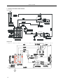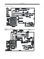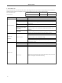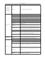
1
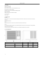
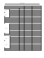
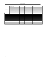
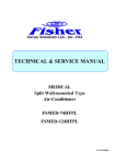
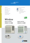
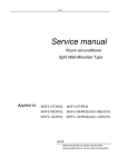
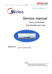
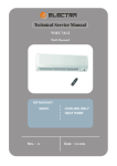
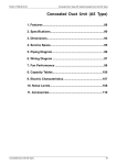
Window Y9USC/E 09 / 12 / 18 B5R SERVICE MANUAL Y9USC-09 B5R; Y9USE-09 B5R Y9USC-12 B5R; Y9USE-12 B5R Y9USC-18 B5R; Y9USE-18 B5R SM-Y9USC-E-09-18GB 03-07 Service manual 1. Precaution ........................................................................................................................................................................................... 2 1.1 safety Precaution............................................................................................................................................................................... 2 1.2 WARNING ......................................................................................................................................................................................... 2 1.3 CAUTION .......................................................................................................................................................................................... 2 1.4 FEATURES ....................................................................................................................................................................................... 3 1.5 DIAGRAM PANEL............................................................................................................................................................................. 3 1.6 OUTSIDE DIMENSIONS .................................................................................................................................................................. 3 1.7 SPECIFICATION............................................................................................................................................................................... 4 2 INSTALLATION .................................................................................................................................................................................. 10 2.1 SELECT THE BEST LOCATION .................................................................................................................................................... 10 2.2 CHECK OFF INSTALLATION......................................................................................................................................................... 10 2.3 HOW TO DRAIN ............................................................................................................................................................................. 11 2.4. HOW TO INSTALL ......................................................................................................................................................................... 11 3 REFRIGERANT CYCLE DIAGRAM .................................................................................................................................................. 13 4 OPERATION LIMITS.......................................................................................................................................................................... 14 4.1 COOLING OPERATION ................................................................................................................................................................. 14 4.2HEATING OPERATION ................................................................................................................................................................... 14 5. TROUBLESHOOTING ................................................................................................................................................................... 17 Service manual 1. PRECAUTION 1.1 SAFETY PRECAUTION To prevent injury to the user or other people and property damage, the following instructions must be followed. Incorrect operation due to ignoring instruction will cause harm or damage. BEFORE SERVICE UNIT, BE SURE TO READ THIS SERVICE MANUAL AT FIRST. 1.2 WARNING 1.2.1 DO NOT USE DAMAGED POWER CORDS, PLUGS, OR A LOOSE SOCKET. 1.2.2 ALWAYS USE THE POWER PLUG AND SOCKET WITH THE GROUND TERMINAL 1.2.3 DO NOT MODIFY OR EXTEND THE POWER CORD 1.2.4 DO NOT TURN THE AIR-CONDITIONER ON OR OFF BY PLUGGING OR UNPLUGGING THE POWER PLUG 1.2.5 USE A DEDICATED POWER OUTLET FOR THIS APPLIANCE 1.2.6 GRASP THE PLUG TO REMOVE THE CORD FROM THE OUTLET. DO NOT TOUCH IT WITH WET HANDS. 1.2.7 DO NOT PLACE A HEATER OR OTHER APPLIANCE NEAR THE POWER CABLE 1.2.8 DO NOT ALLOW WATER TO RUN INTO ELECTRICAL PARTS 1.2.9 DO NOT STORE OR USE FLAMMABLE GAS OR COMBUSTIBLES NEAR THE AIR CONDITIONER 1.2.10 UNPLUGGING THE UNIT IF STRANGE SOUNDS, ODORS, OR SMOKE COMES FROM IT 1.2.11 BE CAUTION THAT WATER COULD NOT ENTER THE PRODUCT 1.3 CAUTION 1.3.1 USE A SOFT CLOTH TO CLEAN. DO NOT USE HARSH DETERGENTS, SOLVENTS, ETC 1.3.2 DO NOT TOUCH THE METAL PARTS OF THE PRODUCT WHEN REMOVING THE AIR FILTER. THEY ARE VERY SHARP 1.3.3 DO NOT STEP ON OR PUT ANYTHING ON THE PRODUCT 1.3.1 DO NOT INSERT HANDS OR OTHER OBJECTS THROUGH THE AIR INLET OR OUTLET WHILE THE AIR CONDITIONER IS PLUGGED IN Service manual 1.4 FEATURES Designed for HEAT PUMP.. Powerful cooling & heating.. Slide-in and slide-out chassis for the simple installation and service. Side air-intake, side cooled-air discharge. WASHABLE ONE-TOUCH FILTER AND EASY REMOVED PANEL. Super compact design. Reliable and efficient rotary compressor is equipped. Unique Quiet Design. Fresh air switch 1.5 DIAGRAM PANEL Auto louver When the switch is on ,the louver motor will operate and begin auto louver function. When the switch is off, the louver motor will stop. Thermostat Set the temperature desired Selector Selector operation function on COOL, HEAT or FAN ONLY with HIGH, MID or LOW fan speed. Test run Turn the knob to this position to operate the unit in FORCED COOLING. Under this mode, the unit will operate in cooling immediately. Wait three minutes before restarting To protect the compressor, please do NOT restart the unit in COOLING or HEATING mode in three minutes. 1.6 OUTSIDE DIMENSIONS Model A (mm) B (mm) C (mm) Y9USC-09 B5R Y9USE-09 B5R 346 450 535 Y9USC-12 B5R Y9USE-12 B5R 400 560 650 Y9USC-18 B5R Y9USE-18 B5R 434 660 650 3 Service manual 1.7 SPECIFICATION Model Y9USC-09 B5R Y9USE-09 B5R Factory Model CE-KC26/E1N2 CE-KCR26/E1N2 Power supply Cooling Heating Ph-V-Hz 1Ph , 220-240V~, 50Hz 1Ph , 220-240V~, 50Hz Capacity Btu/h 9000 9000 Input W 1050 1110 Rated current A 4.7 4.7 EER Btu/w.h 8.6,2.51 8.6,2.51 Capacity Btu/h 9000 Input W 980 Rated current A 4.4 COP W/W 2.7 W/W Moisture Removal L/h 0.9 0.9 Max. input consumption W 1400 1450 Max. current A 7.3 7.5 Starting current A 24 24 Plug type Thermostat type Compressor Mechanical control Mechanical control Model PG180X1C-4DZ3 PG180X1C-4DZ3 Type ROTARY ROTARY Brand TOSHIBA TOSHIBA Capacity Btu/h 10650 10650 Input W 995 995 Rated current(RLA) A 4.6 4.6 Locked rotor Amp(LRA) A 24 24 UP3QE0591-T61 UP3QE0591-T61 Thermal protector Capacitor uF 30 30 Refrigerant oil ml 400 400 R407C/510g R407C/550g 2.6 2.6 Model YSK60-4C YSK60-4C Brand Welling,Broad Welling,Broad Refrigerant type Design pressure Fan motor MPa Input W 112/98/86 112/98/86 Capacitor uF 2.5 2.5 Speed(hi/mi/lo) r/min 1270/1170/1050 1270/1170/1050 3 3 a.Number of rows Evaporator b.Tube pitch(a)x row pitch(b) mm 21X13.37 21X13.37 c.Fin spacing mm 1.2 1.2 Hydrophilic aluminium Hydrophilic aluminium d.Fin type (code) e.Tube outside dia.and type mm 7x0.25, innergroove tube 7x0.25, innergroove tube f.Coil length x height x width mm 248X294X40.11 248X294X40.11 2 2 g.Number of circuits Indoor air flow (Hi/Mi/Lo) m3/h 420/380/330 420/380/330 Indoor noise level (Hi/Mi/Lo) dB(A) 51/48/45 51/48/45 4 Service manual a.Number of rows Condenser 3 3 b.Tube pitch(a)x row pitch(b) mm 21X13.37 21X13.37 c.Fin spacing mm 1.3 1.3 Hydrophilic aluminium Hydrophilic aluminium d.Fin type (code) e.Tube outside dia.and type mm 7x0.25, innergroove tube 7x0.25, innergroove tube f.Coil length x height x width mm 370X315X40.11 370X315X40.11 g.Number of circuits 2 2 m3/h 700/620/540 700/620/540 Outdoor noise level (Hi/Mi/Lo) dB(A) dB(A) 58/55/52 58/55/52 Dimension (W*H*D) mm 450×350×540 450×350×540 Packing (W*H*D) mm 495×435×580 495×435×580 Net/Gross weight Kg 35/39 37/41 Operation temp ℃ 16 Ambient temp ℃ 17 ~ 43 -10 ~ 43 Application area m2 14-20 14-20 Qty’per 20’& 40’HQ Fcl Pieces 220/572 220/572 Outdoor air flow (Hi/Mi/Lo) 5 m3/h 31 16 31 Service manual Model Y9USC-12 B5R Y9USE-12 B5R Factory Model CE-KC35/E1N2 CE-KCR35/E1N2 Power supply Cooling Heating Ph-V-Hz 1Ph , 220-240V~, 50Hz 1Ph , 220-240V~, 50Hz Capacity Btu/h 12000 12000 Input W 1420 1400 Rated current A 6.3 6.2 EER Btu/w.h 8.5,2.48 8.6,2.51 Capacity Btu/h 12000 Input W 1210 Rated current A 5.4 COP W/W 2.9 W/W Moisture Removal L/h 1.1 1.1 Max. input consumption W 1760 1680 Max. current A 9.1 8.5 Starting current A Plug type Thermostat type Compressor Mechanical control Mechanical control Model PG225X2C-4FT PG225X2C-4FT Type ROTARY ROTARY Brand TOSHIBA TOSHIBA Capacity Btu/h 13540 13540 Input W 1290 1290 Rated current(RLA) A 6 6 Locked rotor Amp(LRA) A Not Fixed Not Fixed INTERNAL INTERNAL Thermal protector Capacitor uF 35 35 Refrigerant oil ml 480 480 R407C/870g R407C/900g 2.6 2.6 Model YSK70-6C YSK70-6C Brand Welling,Broad Welling,Broad Refrigerant type Design pressure Fan motor MPa Input W 113/104/100 113/104/100 Capacitor uF 2.5 2.5 Speed(hi/mi/lo) r/min 900/800/700 900/800/700 3 3 a.Number of rows Evaporator b.Tube pitch(a)x row pitch(b) mm 25.4X22 25.4X22 c.Fin spacing mm 1.7 1.7 Hydrophilic aluminium Hydrophilic aluminium d.Fin type (code) e.Tube outside dia.and type mm 9.53x0.27, innergroove tube 9.53x0.27, innergroove tube f.Coil length x height x width mm 317X355.6X66 317X355.6X66 2 2 g.Number of circuits Indoor air flow (Hi/Mi/Lo) m3/h 550/500/450 550/500/450 Indoor noise level (Hi/Mi/Lo) dB(A) 50/47/44 50/47/44 6 Service manual a.Number of rows Condenser 3 3 b.Tube pitch(a)x row pitch(b) mm 25.4X22 25.4X22 c.Fin spacing mm 1.7 1.7 Hydrophilic aluminium Hydrophilic aluminium d.Fin type (code) e.Tube outside dia.and type mm 9.53x0.27, innergroove tube 9.53x0.27, innergroove tube f.Coil length x height x width mm 475X381X66 475X381X66 g.Number of circuits 2 2 m3/h 850/780/700 850/780/700 Outdoor noise level (Hi/Mi/Lo) dB(A) dB(A) 58/55/52 58/55/52 Dimension (W*H*D) mm 560×400×650 560×400×650 Packing (W*H*D) mm 620×445×770 620×445×770 Net/Gross weight Kg 48/53 54/59 Operation temp ℃ 16 Ambient temp ℃ 17 ~ 43 -10 ~ 43 Application area m2 18-26 18-26 Qty’per 20’& 40’HQ Fcl Pieces 133/340 133/340 Outdoor air flow (Hi/Mi/Lo) 7 m3/h 31 16 31 Service manual Model Y9USC-18 B5R Y9USE-18 B5R Factory Model CE-KC46/E1N2 CE-KCR46/E1N2 Power supply Cooling Heating Ph-V-Hz 1Ph , 220-240V~, 50Hz 1Ph , 220-240V~, 50Hz Capacity Btu/h 18000 18000 Input W 2100 2100 Rated current A 9.3 9.3 EER Btu/w.h 8.6,2.5 8.6,2.5 Capacity Btu/h 18000 Input W 2000 Rated current A 9.6 COP W/W 2.7 W/W Moisture Removal L/h 2.0 2.0 Max. input consumption W 3020 3020 Max. current A 15.8 15.8 Starting current A Plug type Thermostat type Compressor Mechanical control Mechanical control Model PG290X2C-4FT1 PG290X2C-4FT1 Type ROTARY ROTARY Brand TOSHIBA TOSHIBA Capacity Btu/h 17700 17700 Input W 1700 1700 Rated current(RLA) A 8.2 8.2 Locked rotor Amp(LRA) A Not Fixed Not Fixed UP3QE0391-T39 UP3QE0391-T39 Thermal protector Capacitor uF 35 35 Refrigerant oil ml 520 520 R407C/870g R407C/1150g 2.6 2.6 Model YSK93-6C YSK93-6C Brand Welling,Broad Welling,Broad Refrigerant type Design pressure Fan motor MPa Input W 143/130/120 143/130/120 Capacitor uF 4 4 Speed(hi/mi/lo) r/min 900/800/700 900/800/700 2 2 a.Number of rows Evaporator b.Tube pitch(a)x row pitch(b) mm 25.4*22 25.4x22 c.Fin spacing mm 1.3 1.5 Hydrophilic aluminium Hydrophilic aluminium d.Fin type (code) e.Tube outside dia.and type mm Ф9.53x0.27, innergroove tube Ф9.53x0.27, innergroove tube f.Coil length x height x width mm 365x381x44 365x381x44 2 2 g.Number of circuits Indoor air flow (Hi/Mi/Lo) m3/h 660/610/560 660/610/560 Indoor noise level (Hi/Mi/Lo) dB(A) 52/49/46 52/49/46 8 Service manual a.Number of rows Condenser 2 3 b.Tube pitch(a)x row pitch(b) mm 25.4x22 25.4x22 c.Fin spacing mm 1.4 1.7 Hydrophilic aluminium Hydrophilic aluminium d.Fin type (code) e.Tube outside dia.and type mm Ф9.53x0.27, innergroove tube Ф9.53x0.27, innergroove tube f.Coil length x height x width mm 560x406x44 560x406x66 g.Number of circuits 2 2 m3/h 1200/1100/1000 1200/1100/1000 Outdoor noise level (Hi/Mi/Lo) dB(A) dB(A) 60/57/54 60/57/54 Dimension (W*H*D) mm 660×435×640 660×435×640 Packing (W*H*D) mm 750×520×740 750×520×740 Net/Gross weight Kg 55/60 59/64 Operation temp ℃ 16 Ambient temp ℃ 17 ~ 43 Application area m2 30-40 30-40 Qty’per 20’& 40’HQ Fcl Pieces 94/240 94/240 Outdoor air flow (Hi/Mi/Lo) m3/h 31 16 31 -10 ~ 45 Note: The noise date is base on hemi-anechoic chamber, during actual operation; these values are normally somewhat different as a result of ambient condition. The above design and specifications are subject to change without prior notice for product improvement. 9 Service manual 2 INSTALLATION 2.1 SELECT THE BEST LOCATION 1. To avoid vibration and noise, make sure the unit is installed securely and firml. 2. Install the unit where the sunlight does not shine directly on the unit. If the unit receives direct sunlight, build an awning to shade the cabinet. 3. There should be no obstacle, such as a fence or wall, within 50cm from the back of the ambient because it will prevent heat radiation of the condenser. 4. Restriction of outside air will greatly reduce the cooling and heating efficiency of the air conditioner. 5. Install the unit on a slight angle so that an condensate formed will not enter the room (about 10mm or 1/4 bubble with level). 6. Install the unit with its bottom portion 75~150cm above the floor level. 7. The power cord must be connected to an independent circuit. The yellow/green wire must be grounded. 2.2 CHECK OFF INSTALLATION The setting conditions must be checked prior to initial starting. The under mentioned items are especially important checking points when the installation is finished. Grounding wire (yellow/Green) is provided in the power cord. The wire must be grounded. Ensure that the unit is connected to a suitably rated and dedicated circuit. To avoid vibration or noise, make sure the air conditioner is installed securely. Avoid placing furniture of draperies in front of the air inlet and outlet. 10 Service manual 2.3 HOW TO DRAIN The base pan ma overflow due to high humidity. To drain the excess water, remove the drain cap from the bottom of the unit (if fitted) and attach a drain hose (not supplied). 1. Take the drain pan which is packed with the unit. 2. Remove the rubber plug from the bottom of the base pan (if fitted). 3. Install the drain pan over the area of the cabinet where you removed the plug, and secure with 2 screws provided. 4. Connect the drain hose to the outlet located at the bottom of the drain pan. You can purchase the drain hose or tubing locally to satisfy our particular needs (Drain hose is not supplied). 2.4. HOW TO INSTALL 2.4.1 INSTALLATION OF THE HOUSING Step1 Remove the air conditioner from it's packaging, remove fixing screws and slide the air conditioner out of it's housing (refer to installation steps) Step2 Prepare the hole in the wall so that the bottom of the housing is well supported, the top has minimum clearance and the air inlet louvers have clearance as shown below in options a and b. Holes from the outside through to the cavity should be sealed. The housing should slope down towards the rear b about 5mm to allow water formed during operation to drain. Step3 Install the housing into the wall and secure. Ensure the foam seals are not damaged. Flash, seal or fill gaps around the inside and outside to provide satisfactory appearance and protection against the weather, insects and rodents. 11 Service manual 2.4.2 INSTALLATION OF THE UNIT INTO THE HOUSING Slide the unit into the housing until it is firmly against the rear of the housing. Care is required to ensure the foam sealing strips on the housing remain in position. Connect the air conditioner to the power and position excess cord length beneath the air conditioner base. Engage the chassis fixing brackets into the bottom housing rail and secure to the base with the screw provided. Remove the front panel from it's carton and plastic bag and fit as per the installation instruction. Switch unit on. Check for operation of the unit and check for vibration in the installation. Fit the drain pan to the housing and run a drain line to a suitable location if required. 2.4.3 INSTALLATION OF THE UNIT INTO THE WALL 2.4.4 INSTALLATION STEPS Step 1. Remove the front panel and the air filter Hold the slot under the front panel, then uplift it outwards, and remove the front panel (See Fig.1). Pinch the handle under the air filter and make the air filter arched, remove it from the slot from underside to upside (See Fig.2). Step 2. Remove the frame. Remove the two fixing screws from the frame (See Fig.3). Grasp the left corner of the frame's underside, then loosen the frame (See Fig.4). Step 3. Installation. Remove the two fixing screws on the chassis fixing brackets, then remove the chassis fixing brackets (See Fig.5). Grasp the handle on the chassis and carefully slide the air conditioner out of the cabinet (See Fig.6). Remove shipping pad from around compressor before operation and make sure the discharge points to the drain pan are aligned before the chassis is pushed into the cabinet (See Fig.7). Push the unit chassis into the cabinet (See Fig.8). Install the two chassis fixing brackets using the two fixing screws (See Fig.5). Step 4. Install the frame. Install the frame making sure not to interfere with the temperature sensor cable (See Fig.9). Fix the screws on the frame (See Fig.3). Step 5. Install the air filter and front panel. Install the air filter into the frame's slot from upside to underside (See Fig.2). Hang the front panel on the frame's buckle, then press the front panel into the frame's slot until you hear a click (See Fig10). 12 Service manual 3 REFRIGERANT CYCLE DIAGRAM The figure below is a brief description of the important components and their function in what is called the refrigeration system. This will help to understand the refrigeration cycle and the flow of the refrigerant in the cooling cycle. 13 Service manual 4 OPERATION LIMITS 4.1 COOLING OPERATION Outdoor unit air temp.ºC DB Indoor air temp. ºC DB Note: The chart is the result from the continuous operation under constant air temperature conditions. However, excludes the initial pull-down stage. 4.2 HEATING OPERATION Indoor air temp. ºC DB Outdoor unit air temp.ºC DB Note: The chart is the result from the continuous operation under constant air temperature conditions. However, excludes the initial pull-down stage. 14 Service manual 5 SCHEMATIC DIAGRAM AND WIRING DIAGRAM Y9USC-09 B5R: Y9USE-09 B5R: 15 Service manual Y9USC-12 B5R Y9USC-18 B5R: Y9USE-12 B5R Y9USE-18 B5R: 16 Service manual 6. TROUBLESHOOTING In general, possible trouble is classified in three kinds. One is called Starting Failure which is caused from an electrical defect, another is ineffective Air Conditioning caused b a defect in the refrigeration circuit and improper application, and the other is called the Structure Damage. ROOM AIRCONDITIONER NAMEPLATE RATING MINIMUM MAXIMUM VOLTAGE LIMITS: 220~240V 196V 253V PROBLEM Fan motor will not run. POSSIBLE CAUSE REMED No power Check voltage at electrical outlet. Correct if none. Power supply cord Check voltage at the power cord terminal. Replace the power cord if none. Wire disconnected or connection Connect wire. Refer to wiring diagram for terminal identification. Repair or replace loose loose terminal. Main switch failure Check and replace the main switch if failure. Capacitor (Discharge capacitor before testing) Test capacitor. Replace if not within +/-10% of manufacture's rating. Replace if shorted, open or damaged. Will not rotate Fan blade hitting shroud or blower hitting scroll. Realign assembly. Check fan motor bearings. Replace the motor if motor shaft do not rotate. Check voltage. Call an electrician if not within limits. Test capacitor. Fan motor runs intermittently Cycles on overload. Replace if not within +/-10% of manufacture's rating. Check bearings. Replace the motor if the fan blade cannot rotate freely. Pay attention to any change from high speed to low speed. Replace the motor if the speed does not change. Fan Replace the fan if cracked, out of balance, or partially missing. Blower Replace the blower if cracked, out of balance, or partially missing. Loose screws Tighten them. Fan motor noise. Worn bearings 17 Replace the motor if knocking sounds continue when running or loose, or the motor hums or noise appears to be internal while running. Service manual The compressor not to stop even the room Thermostat Check and replace if the thermostat is damaged. Air filter Clean or replace if restricted. Vent. door Close if open. Unit undersized Determine if the unit is properly sized for the area to be cooled or heated. Condenser and Evaporator Clean or replace if restricted. Fan motor Check the fan capacitor and replace if not within +/-10% of manufactures rating. Room structure Take proper measures to make the door and windows sealed well if gap is found. Air flow Clean or remove if any barrier is found to block the inlet/outlet wind flow of the unit. Sunlight Add a awning if the condenser is exposed to the sunlight. temp. has got to the setting temperature. Less refrigerant points and recharge. Insufficient cooling or heating. Check the tubes for reasons of leakage. Recycle the refrigerant, correct the leakage Capillary tube Regulate the flow if capillary tube and make the evaporating temperature appropriate if the evaporator is frosted. Replace if blocked. Repair joint if leaking. The inlet and outlet valve of the compressor is damaged, making the low pressure Compressor connected with the high pressure. The refrigerating system can not produce high pressure and low pressure. Replace the compressor after checking for the reason. Heat sources Reduce if too many. The seal in valve is damaged, making the low pressure connected with the high reverse valve pressure. The refrigerating system can not produce high pressure and low pressure. Replace the reverse valve after checking for the reason. Drainage The drainage is blocked. It will increase the efficiency in cooling mode, but will cause the condenser to frost in heating mode. Stop instantly after startup. Refrigerant The amount of the refrigerant is too much, making the compressor load too big. Recycle and recharge the refrigerant after checking for the reason. Compressor The compressor is seized. Replace after checking for the reason. No power Check the voltage. Call an electrician if no within the limit. Wiring Check the terminals. Repair and correct if loose. Temperature setting Check and adjust the thermostat. Main switch setting Check and adjust the main switch setting. No cooling or heating. Reverse valve wire Reverse valve 18 Check the resistance of reverse valve wire. Replace the wire if short, open or damaged. If the reverse valve is blocked, the heating mode will not perform. Replace the reverse valve after checking the reason. Service manual Voltage Check voltage. Call Supply Authority if not within limits. Check the wire connections, if loose, repair or replace the terminal. If wires are off, Wiring refer to wiring diagram for identification, and replace. Check wire locations. If not per wiring diagram, correct. Main switch failure Compressor will not run while fan motor runs. Capacitor (Discharge capacitor before testing) Check and replace the main switch if failure. Check the capacitor. Replace if not within +/-10% of manufacturers rating. Replace if shorted, open, or damaged. Thermostat Check the thermostat setting if not at the coolest (in cooling mode) or the warmest (in heating mode). Set it if not. Compressor Check the compressor for open circuit or ground. If open or grounded, replace the compressor. Excessive noise. Copper tubing Remove the cabinet and carefully rearrange tubing not to contact cabinet, compressor, shroud and barrier. The unit starts and stops Power supply The input power supply voltage is too low. Call an electrician if not within limits. frequently. Outdoor temperature When the outdoor temperature is too high, the compressor will protect. 19 wwwjohnsoncontrols.com SM-Y9USC-E-09-18GB 03-07