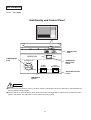
1
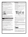
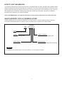
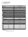
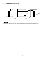
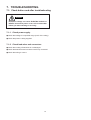
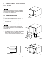
TECHNICAL & SERVICE MANUAL
SA– 128S5
FILE NO.
WINDOW TYPE AIR CONDITIONER
Model No.
Product Code No.
Destination
SA-128S5-A
1 851 004 09
General (50Hz) & Europe
SA– 128S5
REFERENCE NO. SM700338
When Installing
IMPORTANT!
Please Read Before Starting
Place of Installation
• If possible, install the unit in a shady location. If the site
is exposed to the sun, you should provide a sun screen
as shown in Fig. a.
This air conditioner meets strict safety and operating
standards. As the installer or service person, it is an
important part of your job to install or service the system
so it operates safely and efficiently.
• Install it at a spot where optimum cooling circulation can
be obtained. No chairs or other obstructions are allowed
in front of the air conditioner.
For safe installation and trouble-free operation, you
must:
• The back of the air conditioner must extend outside.
(Be sure the right and left intake vents are not obstructed
by walls or windows.)
• Carefully read the INSTRUCTION MANUAL and
INSTALLATION INSTRUCTIONS attached to each air
conditioner before beginning.
• Keep more than 50 cm from any outside obstruction
(wall, bush, etc.).
• Follow each installation or repair step exactly as shown.
• To provide water drainage, the unit must be tilted at a
downward angle 0.5 to 1 cm to the outside.
• Observe all local, state, and national electrical codes.
• Pay close attention to all warning and caution notices
given in this manual.
WARNING
This symbol refers to a hazard or
unsafe practice which can result in
severe personal injury or death.
CAUTION
This symbol refers to a hazard or
unsafe practice which can result in
personal injury or product or property
damage.
Screen
Wall
Support
If Necessary, Get Help
Enough space
from obstacle
or wall.
Room
side
Front
grille
Tilt 0.5 to 1 cm
downward to outside.
• While installing the air conditioner, be sure to loosen the
These instructions are all you need for most installation
sites and maintenance conditions. If you require help for a
special problem, contact our sales/service outlet or your
certified dealer for additional instructions.
Fig. a
compressor locking nuts to avoid abnormal noise and
vibration. (NOTE: Locking nuts are not provided on some
models.)
SPECIAL PRECAUTIONS
WARNING
Outside
• As a safety measure, it is recommended that two people
install the unit: one to hold and balance the unit — the
other to lower the window frame to secure the unit.
When Wiring
ELECTRICAL SHOCK CAN CAUSE SEVERE
PERSONAL INJURY OR DEATH. ONLY A
QUALIFIED, EXPERIENCED ELECTRICIAN
SHOULD ATTEMPT TO WIRE THIS SYSTEM.
• Hold the unit securely, and be careful to not drop the
cabinet or any parts if the air conditioner is being
installed on an upper floor of a multistory building.
• All wiring must conform to local electrical codes.
When Servicing
• Each unit must be properly grounded with a ground (or
earth) wire or through the supply wiring.
• Turn the power OFF at the main power box (mains)
before opening the unit to check or repair electrical parts
and wiring.
• DO NOT, under any circumstances, cut or remove the
third (ground) prong from the power cord plug.
• Keep fingers and clothing away from any moving parts.
• DO NOT use an adapter Plug or extension cord.
• Clean up the site after you finish, remembering to check
that no metal scraps or bits of tools have been left inside
the unit being serviced.
• DO NOT use a damaged power cord, plug, or wall outlet.
Replace them immediately.
• DO NOT change the internal wiring or any part of the
system.
Others
CAUTION
• DO NOT turn the air conditioner on and off by plugging
and unplugging. Use the Operation switch.
• Ventilate any enclosed areas when installing or testing
the refrigeration system. Escaped refrigerant gas, on
contact with fire or heat, can produce dangerously toxic
gas.
When Transporting
Be careful when picking up and moving the air conditioner.
Get a partner to help, and bend your knees when lifting to
reduce strain on your back. Sharp edges or thin aluminum
fins on the air conditioner can cut your fingers.
• Confirm upon completing installation that no refrigerant
gas is leaking. If escaped gas comes in contact with a
stove, gas water heater, electric room heater or other
heat source, it can produce dangerously toxic gas.
i
HOW TO USE THIS MANUAL
This manual is designed to help service personnel to understand basic functions, operation and possible troubles
and their remedies on SANYO window type air conditioners. You can use this manual both as a reference to find
specific information about the capacity, construction of the unit, and as a source of information to help you set up
and maintain the air conditioner. Please use this manual to make your work easier, keep the air conditioner
functioning well, and keep your customer satisfied.
Please read IMPORTANT ! precautional information on the previous page before you start actual work.
SANYO WINDOW TYPE A/C NOMENCLATURE
SANYO window type air conditioner is identified by a model number. Cooling or heating capacity, electrical
information and special features included on the air conditioner are indicated on the model number.
Example
SA – 12 8 S 5
Type
SA : SANYO window type A/C
Capacity
12 : 12,000 BTU/h class
Voltage / Frequency
Design Number
Special Features
5
: 220-240V, 50Hz, Single phase
S : Mechanical Control, Side Air Discharge
NOTE
To identify the correct model number of your air conditioner, you must find the nameplate.
ii
Table of Contents
Page
1. OPERATING RANGE ............................................................................................................................... 1
2. SPECIFICATIONS
2-1. Unit Specifications .......................................................................................................................... 2
2-2. Major Component Specifications.................................................................................................... 3
2-3. Other Component Specifications.................................................................................................... 4
3. DIMENSIONAL DATA............................................................................................................................... 5
4. REFRIGERANT FLOW DIAGRAM .......................................................................................................... 6
5. PERFORMANCE DATA
5-1. Cooling Capacity ........................................................................................................................... 7
6. ELECTRICAL DATA
6-1. Electrical Characteristics ............................................................................................................... 8
6-2. Electric Wiring Diagram .................................................................................................................. 9
7. TROUBLESHOOTING
7-1. Check before and after troubleshooting ........................................................................................ 10
7-2. Air conditioner does not operate .................................................................................................... 11
7-3. Some part of air conditioner does not operate .............................................................................. 13
7-4. Air conditioner operates, but abnormalities are observed ............................................................. 15
8. CHECKING ELECTRICAL COMPONENTS
8-1. Measurement of Insulation Resistance ..........................................................................................
8-2. Checking Motor Capacitor ..............................................................................................................
8-3. Checking Fan Motor Winding .........................................................................................................
8-4. Checking Compressor Motor Winding............................................................................................
16
17
17
17
9. DISASSEMBLY PROCEDURES
9-1. Removing Front Grille ....................................................................................................................
9-2. Removing Electrical Component Box ............................................................................................
9-3. Removing Cabinet .........................................................................................................................
9-4. Removing Evaporator ....................................................................................................................
9-5. Removing Blower Wheel ...............................................................................................................
9-6. Removing Condenser ....................................................................................................................
9-7. Removing Propeller Fan ................................................................................................................
9-8. Removing Fan Motor .....................................................................................................................
18
19
19
20
20
21
21
21
APPENDIX Unit Display and Control Panel ............................................................................................ 22
iii
1. OPERATING RANGE
Temperature
Cooling
Indoor Air Intake Temp.
Outdoor Air Intake Temp.
Maximum
32°C D.B. / 23°C W.B.
43°C D.B.
Minimum
19°C D.B. / 14°C W.B.
19°C D.B.
1
2. SPECIFICATIONS
2-1. Unit Specifications
Model
SA– 128S5
Power Source
220–240V Single phase 50Hz
Voltage rating
220 / 230 / 240 V
Performance
Cooling
Capacity
kW
BTU/h
m3/h
Liters/h
Air circulation (High)
Moisture removal (High)
3.50
11,900
/
/
Electrical Rating
3.55
12,100
620
2.0
/
/
3.55
12,100
/
/
/
/
6.2
1,360
91
2.61
Cooling
Available voltage range
Running amperes
Power input
Power factor
C.O.P.
Starting amperes
V
A
W
%
W/W
A
6.3
1,300
94
2.69
/
/
/
/
198 ~ 264
6.2
1,340
94
2.65
34
Features
Controls / Temperature control
Control unit
Timer
Fan speeds
Airflow direction (Indoor)
Air filter / Air exhaust
Compressor
Refrigerant / Amount charged at shipment
Refrigerant control
Operation sound
Indoor : Hi / Lo
Outdoor : Hi / Lo
Slide-out chassis
Accessories
Mechanical / Thermostat
—
—
2
Auto
Manual
Washable / Yes
Rotary (Hermetic)
R22 / 780
Capillary tube
52 / 50
56 / 52
Yes
—
Horizontal
Vertical
g
dB-A
dB-A
Dimensions & Weight
Unit dimensions
Package dimensions
Weight
Shipping volume
Height
Width
Depth
Height
Width
Depth
Net
Shipping
mm
mm
mm
mm
mm
mm
kg
kg
m3
375
530
620
435
600
725
44.0
47.0
0.19
Remarks:
Rating conditions are:
Cooling : Indoor air temperature 27°C D.B. / 19°C W.B.
Outdoor air temperature 35°C D.B. / 24°C W.B.
2
DATA SUBJECT TO CHANGE WITHOUT NOTICE.
2-2. Major Component Specifications
Model
SA– 128S5
Controller
PCB
Part No.
Controls
Control circuit fuse
—
—
—
Remote Control Unit
—
Compressor
Type
Compressor model
Source
Nominal output
Compressor oil ... Amount
Coil resistance (Ambient temp. 25°C)
Safety devices
Run capacitor
Rotary (Hermetic)
C-R110H5H 80619445
220–240V Single phase 50Hz
1,100
SUNISO 4GSD-T ... 550
C–R : 1.962
C–S : 5.38
External protector
MRA98619-9200
150±5
69±11
Trip in 6 to 16 sec. at 22.5A
25.0
400
W
cc
Ω
Type
Overload relay
Operating temp.
Open
°C
Close
°C
Operating amp.(Ambient temp. 25°C)
µF
VAC
Fan & Fan Motor
Indoor
Type
Dia. / Depth
Fan motor model ... Q'ty
Source
No. of poles ... rpm (230 V, High)
Nominal output
Coil resistance (Ambient temp. 20°C)
Safety devices
Run capacitor
Type
Operating temp.
Centrifugal
Propeller
ø210 / D96
ø320 / D —
YSK70-4A-661 ... 1
220–240V Single phase 50Hz
4 ... 1,010
20
WHT-BRN : 60.0
WHT-YEL : 19.6
YEL-ORG(PNK) : 62.7
Internal protector
130±5
Automatic reclosing
3.5
440
mm
W
Ω
Open
Close
Outdoor
°C
°C
µF
VAC
Heat Exch. Coil
Coil
Rows
Fin pitch
Face area
Evaporator
2
1.4
0.095
mm
m2
External Finish
Condenser
3
1.6
0.155
Acrylic baked-on enamel finish
DATA SUBJECT TO CHANGE WITHOUT NOTICE.
3
2-3. Other Component Specification
Model
SA – 128S5
Auto Deflector Motor
M16B
Rating
Coil resistance
AC 220-240V, 50/60Hz, 3 W, 4.2/5.0 rpm
11.15 ± 5%
kΩ (at 25°C)
4
3. DIMENSIONAL DATA
Model
SA – 128S5
✽ 248
620
530
248
375
40
Side view (L)
Power code
outlet
Front view
Power code
outlet
Slits for
ventilation
Side view (R)
Unit : mm
NOTE
Dimension with "✻" mark indicates the maximum allowable wall thickness required for ventilating the unit.
5
4. REFRIGERANT FLOW DIAGRAM
SA–128S5
Accumulator
Compressor
Condenser
Evaporator
Model
Capillary
Strainer
tube
6
5. PERFORMANCE DATA
5-1. Cooling Capacity
Model
SA–128S5
240V Single Phase 50Hz
RATING CAPACITY
AIR FLOW RATE
EVAPORATOR
ENT. TEMP. °C
W.B.
D.B.
3.55 kW
620 m3/h
CONDENSER
OUTDOOR AMBIENT TEMP. °C
20
25
30
35
40
TC
3.58
3.42
3.27
3.11
2.92
CM
0.90
0.98
1.04
1.12
1.26
21
SHC
2.32
2.24
2.15
2.07
1.97
15
23
SHC
2.59
2.51
2.42
2.34
2.25
25
SHC
2.86
2.78
2.69
2.61
2.52
27
SHC
3.13
3.05
2.97
2.88
2.79
29
SHC
3.40
3.32
3.24
3.11
2.92
31
SHC
3.58
3.42
3.27
3.11
2.92
TC
3.84
3.67
3.50
3.34
3.14
CM
0.93
1.00
1.07
1.15
1.29
21
SHC
2.04
1.95
1.87
1.79
1.69
17
23
SHC
2.31
2.22
2.14
2.06
1.96
25
SHC
2.58
2.50
2.41
2.33
2.23
27
SHC
2.85
2.77
2.68
2.60
2.51
29
SHC
3.12
3.04
2.95
2.87
2.78
31
SHC
3.39
3.31
3.23
3.14
3.05
TC
4.08
3.91
3.73 # 3.55
3.34
CM
0.96
1.03
1.11
1.19
1.33
21
SHC
1.74
1.66
1.57
1.49
1.40
19
23
SHC
2.01
1.93
1.84
1.76
1.67
25
SHC
2.28
2.20
2.12
2.03
1.94
27
SHC
2.55
2.47
2.39
2.31
2.21
29
SHC
2.82
2.74
2.66
2.58
2.48
31
SHC
3.10
3.01
2.93
2.85
2.75
TC
4.33
4.14
3.95
3.76
3.54
CM
0.98
1.06
1.14
1.22
1.37
23
SHC
1.71
1.62
1.54
1.46
1.37
21
25
SHC
1.98
1.90
1.81
1.73
1.64
27
SHC
2.25
2.17
2.09
2.01
1.91
29
SHC
2.52
2.44
2.36
2.28
2.18
31
SHC
2.79
2.71
2.63
2.55
2.45
TC
4.59
4.39
4.19
3.95
3.70
CM
1.00
1.09
1.17
1.25
1.40
23
25
SHC
1.66
1.58
1.49
1.40
1.31
27
SHC
1.93
1.85
1.76
1.67
1.58
29
SHC
2.20
2.12
2.04
1.94
1.85
31
SHC
2.47
2.39
2.31
2.22
2.12
TC : Total Cooling Capacity (kW)
SHC : Sensible Heat Capacity (kW)
CM : Compressor Input (kW)
Rating conditions (#Mark) are
Outdoor Ambient Temp. 35°C D.B.
Indoor Unit Entering Air Temp. 27°C D.B. / 19°C W.B.
7
45
2.69
1.40
1.86
2.13
2.40
2.67
2.69
2.69
2.89
1.43
1.58
1.85
2.12
2.39
2.66
2.89
3.07
1.47
1.28
1.55
1.82
2.09
2.37
2.64
3.25
1.51
1.26
1.53
1.80
2.07
2.34
3.44
1.55
1.21
1.48
1.75
2.02
6. ELECTRICAL DATA
6-1. Electrical Characteristics
Model
SA – 128S5
Fan Motor
Performance at
Rating Conditions
Compressor
Complete Unit
220–240V Single phase 50Hz
Running Amps.
Power Input
Full Load Conditions Running Amps.
Power Input
A
0.69 / 0.73
5.6
kW 0.152 / 0.173
A
0.69 / 0.73
kW 0.152 / 0.173
Rating Conditions
/
5.5
6.3
1.15 /
1.19
1.30 /
1.36
7.2
7.0
7.9
7.7
1.55
1.67 /
/
1.52 /
: Indoor Air Temperature 27°C D.B. / 19°C W.B.
Outdoor Air Temperature 35°C D.B.
Full Load Conditions : Indoor Air Temperature 32°C D.B. / 23°C W.B.
Outdoor Air Temperature 43°C D.B.
8
/
/
6.2
1.72
6-2. Electrical Wiring Diagrams
To avoid electrical shock hazard, be sure to
disconnect power before checking, servicing
and/or cleaning any electrical parts.
SA-128S5
WARNING
BRN
2
1
C
RED
L
BLK
R
S
Capacitor
1a
BLU
BLU
CM
BLK
p
C
GRN/YEL
(PNK)
FM
BRN
ORG
Fan motor
DS
RED
YEL
WHT
1a
RED
p
Capacitor
Auto deflector swithc
Power supply
RED
1b
BLK
Auto deflector motor
GRN/YEL
(2)
Fan speed switch
N
GRN/YEL
RED
(1)
BLU
Overload relay
L
Thermostat (Room)
Compressor motor
BRN
Operation switch
WHT
Terminal plate
GRN/YEL
Model
BLU
BLU
DATA SUBJECT TO CHANGE WITHOUT NOTICE.
9
7. TROUBLESHOOTING
7-1. Check before and after troubleshooting
WARNING
Hazardous voltage can cause ELECTRIC SHOCK or
DEATH. Disconnect power or turn off circuit breaker
before you start checking or servicing.
7-1-1. Check power supply.
● Check that voltage is in specified range (±10% of the rating).
● Check that power is being supplied.
7-1-2. Check lead wires and connectors.
● Check that coating of lead wires is not damaged.
● Check that lead wires and connectors are firmly connected.
● Check that wiring is correct.
10
7-2. Air conditioner does not operate.
7-2-1. Circuit breaker trips (or fuse blows).
A. When the circuit breaker is set to ON, it is tripped soon. (Resetting is not possible.)
● There is a possibility of ground fault.
● Check insulation resistance.
If resistance value is 2MΩ or less, insulation is defective (“NO”).
Power plug
(Field supply)
Wall outlet
(Receptacle)
1
Circuit
breaker
Window type air conditioner
Power
supply
Ground
WARNING
* Set circuit breaker to OFF.
1
Pull the power plug out of the
wall outlet.
• Measure insulation resistance
of unit.
Insulation of
unit is
defective.
NO
• Measure insulation
resistance of electrical
parts.
(Example)
Compressor, Fan motor,
Capacitor, Relay etc.
NOTE
1. If any poorly insulated part is found, exclude that part from circuit with other parts properly connected, and then
measure insulation resistance of entire air conditioner again to locate defective part.
2. Replace defective part with new one.
11
B. Circuit breaker trips in several minutes after turning the air conditioner on.
● There is a possibility of short circuit.
• Check capacity of circuit breaker.
Replace with suitable
one (larger capacity).
NO
Capacity of circuit breaker is
suitable.
• Measure resistance of fan motor
winding.
• Measure resistance of compressor
motor winding.
7-2-2. Neither fan motor nor compressor motor runs.
A. Power is not supplied.
• Check power supply.
Circuit breaker
is tripped.
Reset breaker.
Power failure.
Wait for recovery
or contact power
company.
NO
Power is being supplied to the unit.
B. Check OPERATION SELECTOR switch on the control panel.
• Check that OPERATION SELECTOR
switch is not set at "OFF".
If it is set at OFF.
12
Set to "ON" .
7-3. Some part of air conditioner does not operate.
7-3-1. Only fan does not run.
• Check fan rotation.
Turn fan gently once or twice by
hand.
• Check fan casing
foreign matter on
inside.
Fan cannot
be turned.
Fan motor burnout
or foreign matter in
bearings.
• Measure resistance of fan motor
winding.
OK
• Check fan motor capacitor.
7-3-2. Auto deflector switch does not work.
• Measure resistance of auto deflector
motor winding.
13
Remove foreign
matter or repair.
Repair or replace.
7-3-3. Only compressor does not run.
A. Check setting temperature.
Is room temperature too low ?
NO
Try to lower setting temperature by
thermostat knob COOLER.
B. Check compressor and electrical parts.
Overload relay is working.
• Check compressor motor
capacitor.
YES
• Measure resistance of
compressor motor winding.
Temperature of compressor
is abnormally high.
YES
YES
Refrigerant gas shortage.
Charge refrigerant gas (R22).
NO
• Measure power supply
voltage.
The voltage is too low.
No
Rotor may be locked up.
CAUTION
● If the unit is turned off during cooling, DO NOT restart it immediately, as this can damage it. Wait at least three
minutes before starting it again.
14
7-4. Air conditioner operates, but abnormalities are observed.
7-4-1. Poor cooling
• Measure temperature of suction and
discharge air of air conditioner.
Temperature
difference
is small.
Possibility of
gas shortage.
Charge refrigerant
gas (R22).
Temperature difference between
suction and discharge air is
large enough (approx. 10 deg. or more).
Check for clogging of air filter.
Clean filter.
Air filter is clogged.
• Fan speed is set to LOW.
YES
Set fan speed to
HIGH.
• Review cooling load estimate,
if performance of air conditioner is
normal.
Reduce cooling load or
replace the air conditioner
with larger capacity.
7-4-2. Excessive cooling
• Set temperature is suitable.
Set temperature to higher
value using thermostat on the
control panel.
NO
15
8. CHECKING ELECTRICAL COMPONENTS
8-1. Measurement of Insulation
Resistance
Power plug
(Field supply)
● The insulation is in good condition if the resistance
exceeds 2MΩ.
Ground
Probe
8-1-1. Power Cord and Unit
Insulation tester
Clamp the grounding prong of the power plug with a lead
clip of the insulation resistance tester and measure the
resistance by placing a probe on either of the two power
blade. (Fig. 1)
Fig. 1
NOTE
● The shape of the power plug may differ from that of
the air conditioner which you are servicing.
Then, also measure the resistance between the grounding
prong and other power blade. (Fig. 1)
8-1-2. Measurement of Insulation Resistance
for Electrical Parts
Disconnect the lead wires of the desired electric part from
terminal plate, switch, capacitor, etc. Similarly disconnect
the connector. Then measure the insulation resistance.
(Figs. 2 to 3)
Probe
Clip
Refer to Electric Wiring Diagram.
Copper
tube or
metallic part
NOTE
If the probe cannot enter the poles because the hole is too
narrow then use a probe with a thinner pin.
Insulation
tester
Fig. 2
From fan motor,
compressor and
other parts
Metallic
part
Probe
Clip
Insulation
tester
16
Fig. 3
8-2. Checking Motor Capacitor
Remove the lead wires from the capacitor terminals, and
then place a probe on the capacitor terminals as shown in
Fig. 4. Observe the deflection of the pointer, setting the
resistance measuring range of the multimeter to the
maximum value.
Multimeter
The capacitor is “good” if the pointer bounces to a great
extent and then gradually returns to its original position.
The range of deflection and deflection time differ according
to the capacity of the capacitor.
8-3. Checking Fan Motor Winding
Referring to the electrical diagram, disconnect fan motor
connectors, and measure the resistance between each lead
wire with a tester.
Compressor motor
capacitor
The tester should be set in the X1 range. If the fan motor is
hot, allow a few minutes until it gets cooled down.
Fan motor
capacitor
Fig. 4
When the resistances between each lead wire are those
listed in "2-2. Major Component Specifications" the fan
motor should be normal.
Multimeter
,,,,,,,,,,
,,,,,,,,,,
,,,,,,,,,,
,,,,,,,,,,
,,,,,,,,,,
,,,,,,,,,,
,,,,,,,,,,
,,,,,,,,,,
,,,,,,,,,,
,,,,,,,,,,
8-4. Checking Compressor Motor
Winding
Checking compressor motor winding can be done in the
similar manner.
Remove the terminal cover of the compressor motor, set the
resistance measuring range of the multimeter to "X1Ω" and
check the continuity between each pair out of the
3 terminals as shown in Fig. 5.
Refer to "2-2. Major Component Specifications" for coil
resistance.
17
Compressor motor
coil terminal
Fig. 5
9. DISASSEMBLY PROCEDURES
Model
SA– 128S5
NOTE
These illustrations are based on typical view of a standard
model. Consequently, the shape may differ from that of the
air conditioner which you are servicing.
9-1. Removing Front Grille
Fig. 1
Screw holding
the grille
(1) Pull out the filter.
(2) Remove the screw holding the grille in place. (Fig. 1)
(3) Slide the side of the grille to the left and right to
disengage the tabs on the left and right sides of the
grille from the slots.
(4) Pull the bottom portion of the grille toward you while
paying attention to the ventilator lever. (Fig. 2 and 4)
NOTE
Pulling out too far on the bottom of the grille at this point
could damage the tabs at the top. Do not pull the grille out
more than 100 mm.
Grille
Cabinet
(5) After confirming that the ventilator lever has been
disengaged from the grille vent, slide the grille upward to
free the two tabs at the top of the grille from the
rectangular holes in the top of the cabinet. (Fig. 3 and 4)
Slot
Tab
Pull out 70mm –
100mm
Fig. 2
Slot
Tab
Grille
Vent
Cabinet
Ventilator lever
Fig. 3
Fig. 4
18
9-2. Removing Electrical Component
Box
(1) Remove the front grille. (Fig. 5)
Refer to "9-1. Removing Front Grille"
(2) Remove screws securing the electrical component box.
(Fig. 6)
Fig. 5
Fig. 6
9-3. Removing Cabinet
(1) Remove screws holding the unit. (Fig. 7)
(2) Remove the front grille.
Refer to "9-1. Removing Front Grille"
(3) Remove the stopper screw attached to the base pan of
the unit (Fig. 8)
(4) While holding top of the cabinet with one hand, grasp
the handle with another hand and pull the unit toward
you. (Fig. 9)
Fig. 7
Fig. 9
19
Stopper
Fig. 8
9-4. Removing Evaporator
(1) Remove screws holding top plate of evaporator.
(Fig. 10)
(2) Remove screws holding evaporator. (Fig. 10)
(3) Grasp lower portion of the evaporator with both hands
and tilt it slightly and lift it carefully from the drain pan so
as not to distort the copper tube.
Fig. 10
9-5. Removing Blower Wheel
(1) Remove the evaporator.
Refer to "9-4. Removing Evaporator"
(2) Loosen a nut holding blower wheel on motor shaft using
hex wrench. (Fig. 11)
(3) Remove the housing of blower wheel.
(4) Extract the blower wheel from the motor shaft.
Fig. 11
20
9-6. Removing Condenser
(1) Remove two splasher plates A and B
on both side of condenser. (Fig. 12)
B
A
(2) Remove splasher plate C at the back
of condenser.
(Fig. 12)
(3) Remove other screws holding the
condenser.
(Fig. 12)
(4) Grasp lower portion of the condenser
with both hands and tilt it slightly and
lift it carefully from the base pan so
as not to distort the copper tube.
C
Fig. 12
9-7. Removing Propeller Fan
(1) Remove the condenser.
Refer to "9-6. Removing Condenser"
(2) Loosen a nut holding propeller fan on motor shaft using
hex. wrench. (Fig. 13)
NOTE
To loose the nut securing the propeller fan, hold the fan with
one hand and turn the nut COUNTERCLOCKWISE with
another hand.
(3) Extract the propeller fan from the motor shaft.
Fig. 13
9-8. Removing Fan Motor
(1) Remove blower wheel.
Refer to "9-5. Removing Blower Wheel"
(2) Remove propeller fan.
Refer to "9-7. Removing Propeller Fan"
(3) Disconnect motor lead wires.
Refer to "9-2. Removing Electrical Component Box"
(4) Remove 4 screws of the fan motor mounting plate with a
philip screwdriver. (Fig. 14)
(5) Disengage the fan motor from the mounting plate.
Fig. 14
21
APPENDIX
Model
SA– 128S5
Unit Display and Control Panel
VENTILATOR
lever
OPERATION
THERMOSTAT
knob
OFF
ON
THERMOSTAT
7
9
5
11
3
1
FAN
SPEED
COOLER LOW
AUTO
DEFLECTOR
HIGH OFF
WAIT 3 MINUTES BEFORE RESTARTING
OPERATION
SELECTOR
switch
ON
AUTO DEFLECTOR
switch
FAN SPEED
selector
CAUTION
● If the unit is turned off during cooling, DO NOT restart it immediately, as this can damage it. Wait at least three
minutes before starting it again.
● Set the selector to TEST RUN only when performing a test cooling operation. Never leave the selector in this
position. Otherwise, the evaporator coil may freeze up during cooling.
22
SANYO Electric Co.,Ltd
Osaka, Japan
SM700338
Printed in Japan
04/98/200