1
IMPORTANT
southbend
A MIDDLEBY COMPANY
FOR FUTURE REFERENCE
Please complete this information and
retain this manual for the life of the
equipment.
MODEL# __________________________
SERIAL # __________________________
DATE PURCHASED ________________
OWNER'S MANUAL
INSTALLATION
USER'S GUIDE
SERVICE PARTS
HEAVY DUTY
RESTAURANT RANGES
With Standard Oven Bases
300,301,302,303,304
320,321,322,323
With Convection Oven Bases
CO-300, CO-301, CO-302, CO-303, CO-304
CO-320, CO-321, CO-322, CO-323
(Thermostatic Griddle Models Have Prefix "T")
(Includes All Models With Suffixes B, C, D or F)
MODELS:
These instructions should be read thoroughly before attempting installation. Installation and Start
Up should be performed by a qualified service technician. The Manufacturer, Southbend (Head
Office: 1100 Old Honeycutt Rd., Fuquay-Varina, North Carolina 27526), informs you that unless
the installation instructions for the above described Southbend product are followed and
performed by a qualified service technician, (a person experienced in and knowledgeable
concerning the installation of commercial gas and/or electrical cooking equipment) then the terms
and conditions of the Manufacturer's Limited Warranty will be rendered void and no warranty of
any kind shall apply. If the equipment has been changed, altered, modified or repaired by other
than a qualified service technician during or after the 12-month limited warranty period, then the
manufacturer shall not be liable for any incidental or consequential damages to any person or to
any property which may result from the use of the equipment thereafter. Some States do not
allow the exclusion or limitation of incidental or consequential damages, so the above limitation or
exclusion thereto may not apply to you.
In the event you have any questions concerning the installation, use, care, or service of the
product, write Customer Service Department, Southbend, 1100 Old Honeycutt Rd., FuquayVarina, North Carolina 27526.
WARNING: Improper installation, adjustment, alteration, service
or maintenance can cause property damage, injury or death.
Read the installation, operating and maintenance instructions
thoroughly before installing or servicing this equipment.
$4.00
RESTAURANT RANGES
(Manual Section RR)
Congratulations! You have just purchased one of the finest pieces of heavy-duty, commercial cooking
equipment on the market today.
You will find that your new equipment, like all Southbend equipment, has been designed and
manufactured to some of the toughest standards in the industry — those of Southbend. Each piece
of Southbend equipment has been carefully engineered and designs have been verified through
laboratory tests and field installations in some of the more strenuous commercial cooking
applications. With proper care and field maintenance, you will experience years of reliable, troublefree operation from your Southbend equipment. To get the best results, it's important that you read
this manual carefully.
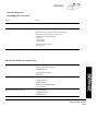
TABLE OF CONTENTS:
SECTION ONE - INSTALLATION
Specifications ......................................................................... 1
Installation .............................................................................. 2
SECTION TWO - USER'S GUIDE
Warranty ................................................................................. 1
Operation ................................................................................ 2
Cooking Hints ........................................................................ 9
Maintenance ......................................................................... 11
SECTION THREE – SERVICE
Adjustments ........................................................................... 1
Service .................................................................................... 7
Trouble Shooting .................................................................... 8
Schematic Drawings ............................................................. 12
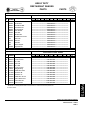
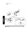
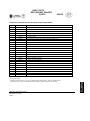
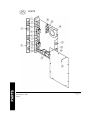
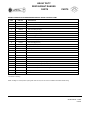
SECTION FOUR – PARTS
Parts List ................................................................................ 1
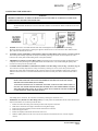
CAUTION: POST IN PROMINENT LOCATION INSTRUCTIONS TO BE FOLLOWED
IN THE EVENT THE SMELL OF GAS IS DETECTED. THIS INFORMATION
SHALL BE OBTAINED FROM LOCAL GAS SUPPLIER.
RETAIN THIS MANUAL FOR FUTURE REFERENCE.
INTENDED FOR COMMERCIAL USE ONLY. NOT FOR HOUSEHOLD USE.
FOR YOUR SAFETY
DO NOT STORE OR USE GASOLINE OR OTHER FLAMMABLE VAPORS AND LIQUIDS
IN THE VICINITY OF THIS OR ANY OTHER APPLIANCE.
KEEP AREA AROUND APPLIANCES FREE AND CLEAR FROM COMBUSTIBLES.
IN THE EVENT A GAS ODOR IS DETECTED, SHUT DOWN EQUIPMENT AT THE MAIN
SHUTOFF VALVE AND CONTACT THE LOCAL GAS COMPANY OR GAS SUPPLIER FOR
SERVICE.
southbend
A MIDDLEBY COMPANY
1100 Old Honeycutt Road
Fuquay-Varina, NC 27526
(919) 552-9161
FAX (919) 552-9798
(800) 348-2558
HEAVY DUTY
RESTAURANT RANGE
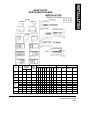
INSTALLATION
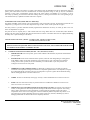
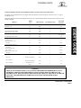
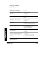
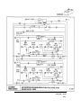
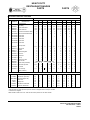
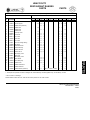
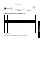
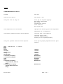
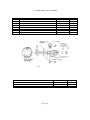
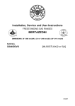
SPECIFICATIONS
NAT.
PROP.
Stnd.
Oven
4" W.C. 10" W.C.
32.000
Stnd.
Oven
10" W.C.
30.000
4" W.C. 10" W.C.
25.000
1
1
1
1
1
2
Conv.
Oven
Nat./L.P.
Open Top
Comb.
Griddle
Broiler
Griddle
Hot Top
323
322
321
320
304
303
302
NUMBER PER UNIT
301
SECTION BURNER
RATE
PER
BURNER
BTUs/HR.
300
MANIFOLD
PRESSURE
ORIFICE SIZE
PART NUMBER
NATURAL PROPANE
DMS
DMS
NATURAL PROPANE
#36
1008736
#52
2
2
2
#42
#53
1008752
1008742
1008753
4" W.C. 10" W.C.
20,000
6
2
0
6
4
10
6
4
6
#45
#54
1008745
1008754
Rt. & Lt.
4" W.C. 10" W.C.
15.000
0
0
0
0
0
0
0
0
2
#49
#57
1008749
1008757
Rt. & Lt.
4" W.C. 10" W.C.
12,000
0
0
0
2
2
0
0
0
0
#51
#57
1008751
1008757
Center
4" W.C. 10" W.C.
9.500
0
0
0
1
1
0
0
0
1
#53
#65
1008753
1008765
Main
4" W.C. 10" W.C.
16,000
0
3
4
0
0
0
3
4
0
#48
#56
1008748
1008756
Left
4" W.C. 10- W.C.
10.000
0
0
0
0
1
0
0
0
0
#53
#65
1008753
1008765
4" W.C. 10" W.C,
12.000
#51
#57
1008751
1008757
W.C. = Water Column
Opt Opt N/A Opt Opt Opt Opt Opt Opt
*Standard or Convection Oven
HEAVY DUTY RESTAURANT RANGES
SECTION ONE — INSTALLATION
PAGE 1
INSTALLATION
WARNING: THESE PROCEDURES MUST BE FOLLOWED BY QUALIFIED PERSONNEL OR
WARRANTY WILL BE VOIDED.
GENERAL:
The installation must conform with local codes, or in the absence of local codes, with the National Fuel Gas Code,
ANSI Z223.1-Latest Edition. In addition, units with the Convection Oven Base must be electrically grounded and
comply with local codes, or in the absence of local codes, with the National Electrical Code ANSI/NFPA 70-1987.
Canadian installation must comply with CAN/CGA-B 149.1 Natural Gas Installation Code, Code CAN/CGA-B
149.2 Propane Installation Code. Canadian Electrical Code Parts I, or Local Codes and CSA C22.1.
These models are design certified for operation on Natural or Propane gases. The appliance should be connected
ONLY to the type of gas for which it is equipped. All Southbend equipment is adjusted at the factory, however,
burner air shutters and pilot heights should be checked at installation and adjusted if necessary. Check type of gas
on serial plate in the compartment below the oven on the right side (on double oven units - left oven). For orifice
sizes and pressure regulator settings refer to the chart under "SPECIFICATIONS."
An adequate gas supply is imperative. Undersized or low pressure lines will restrict the volume of gas required for
satisfactory performance. A pressure regulator, which is provided with each unit, is set to maintain a 4" W.C.
manifold pressure for natural gas and 10" W.C. manifold pressure for propane gas. However, to maintain these
conditions the pressure on the supply line, when all units are operating simultaneously, should not drop below 7"
W.C. for natural gas or 11" W.C. for propane gas.
All pipe joints should be tested for leaks with a soap and water solution before operating the unit. The test pressure
should not exceed 14" W.C. A 1/8" pressure tap is located on the gas manifold.
CAUTION: THIS APPLIANCE AND ITS INDIVIDUAL SHUTOFF VALVE MUST BE
DISCONNECTED FROM THE GAS SUPPLY PIPING SYSTEM DURING ANY PRESSURE TESTING
OF THAT SYSTEM AT TEST PRESSURES IN EXCESS OF 1/2 PSIG (3.45 kPa).
THIS APPLIANCE MUST BE ISOLATED FROM THE GAS SUPPLY PIPING SYSTEM BY CLOSING
ITS INDIVIDUAL MANUAL SHUTOFF VALVE DURING ANY PRESSURE TESTING OF THE GAS
SUPPLY PIPING SYSTEM AT TEST PRESSURES EQUAL TO OR LESS THAN 112 PSIG (3.45 kPa).
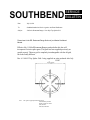
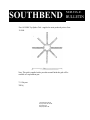
EXHAUST FANS AND CANOPIES:
Be sure to inspect and clean ventilation system according to the ventilation equipment manufacturers instructions.
Canopies are set over ranges, ovens, etc., for ventilation purposes. It is recommended that a canopy extend 6" past
appliance and be located 6'6" from the floor. Filters should be installed at an angle of 45 degrees or more with the
horizontal. The prevents dripping grease and facilitates collecting the run-off grease in a drip pan, usually installed
with a filter. A strong exhaust fan tends to create a vacuum in the room and may interfere with burner performance or
may extinguish pilot flames. Fresh air openings approximately equal to the fan area will relieve such vacuum. In case
of unsatisfactory performance on any appliance, check with the exhaust fan in the "OFF" position.
WALL EXHAUST FAN: Should be installed at least 2 feet above the vent opening at the top of the shelf or
backsplash.
NOTE: Due to the variety of problems encountered by outside weather conditions, venting by canopies or wall fans
are preferred over any type of direct venting.
WARNING: ALL UNITS MUST BE INSTALLED IN SUCH A MANNER THAT THE FLOW OF
COMBUSTION AND VENTILATION AIR ARE NOT OBSTRUCTED. PROVISIONS FOR AN
ADEQUATE AIR SUPPLY MUST ALSO BE PROVIDED. DO NOT OBSTRUCT THE FRONT OF THE
UNIT AT THE TOP BY THE CONTROL PANEL, OR THE BOTTOM JUST BELOW THE OVEN
COMPARTMENT, AS COMBUSTION AIR ENTERS THROUGH THESE AREAS.
HEAVY DUTY RESTAURANT RANGES
SECTION ONE - INSTALLATION
PAGE 2
Litho in
U.S.A. 4-92
NOTICE: THERE MUST BE ADEQUATE CLEARANCE BETWEEN UNITS AND COMBUSTIBLE
CONSTRUCTION. CLEARANCE MUST ALSO BE PROVIDED FOR SERVICING AND FOR OPERATION.
WARNING: ON UNITS WITH THE CONVECTION-TYPE OVEN, A MINIMUM CLEARANCE OF TWO INCHES
MUST BE ALLOWED BEHIND THE MOTOR AND ANY REAR NON-COMBUSTIBLE ENCLOSURE. CARE MUST
BE TAKEN TO PROVIDE ADEQUATE AIR CIRCULATION TO PREVENT THE MOTOR FROM OVERHEATING.
NO ADDITIONAL CLEARANCE FROM THE SIDES AND BACK IS REQUIRED FOR SERVICE AS THE UNITS
ARE SERVICEABLE FROM THE FRONT.
MINIMUM CLEARANCES FROM COMBUSTIBLE CONSTRUCTION:
I. Standard Oven Base Units
6 INCHES FROM SIDES
6 INCHES FROM BACK
6 INCHES FROM FLOOR
II. Convection-Type Oven Base Units
A. Single oven base range units - 8 inches from the sides, 8 inches from the rear and 6 inches from the floor.
B. Double oven base range units - 6 inches from the sides, 8 inches from the rear and 6 inches from the floor.
RANGES WITH SOLID TOPS, such as Griddles or Hot Tops, must always have venting for their flue products
at the rear of their burner compartments provided by the hollow area inside a shelf 21" high or a backsplash 17"
high. Lack of sufficient venting for the burners in these compartments will cause poor burner and pilot operating
characteristics, resulting in inefficient performance. Such conditions also cause high ambient temperatures at the
manifold area and create valve and thermostat problems.
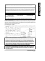
LEGS OR OPTIONAL CASTERS:
1. A set of legs or casters are packed in the unit. A threaded receptacle is fastened to the base
frame at each comer. Each leg or caster has a similar mating thread. Install casters with locking brake to the
front of unit.
2. Raise unit sufficiently to allow legs or
casters to be screwed into the receptacles.
For safety, "shore up" and support the unit
with
an
adequate
blocking
arrangement
strong enough to support the load.
3. Lower unit gently. Never drop or allow the
unit to fall.
4. The legs or casters can be adjusted to
overcome an uneven floor.
5. After the unit has been leveled, tighten the
lock nuts. (Lock nuts supplied with casters
only.)
6. Casters are provided with a Zerk fitting for proper lubrication when required.
WARNING:
FOR AN APPLIANCE EQUIPPED WITH CASTERS, THE INSTALLATION SHALL BE MADE
WITH A CONNECTOR THAT COMPLIES WITH THE STANDARD FOR CONNECTORS FOR
MOVABLE GAS APPLIANCES. ANSI Z21.69.1987, CAN1 6.10-88 AND A QUICK-DISCONNECT
DEVICE THAT COMPLIES WITH THE STANDARD FOR QUICK-DISCONNECT DEVICES FOR
USE WITH GAS FUEL, ANSI Z21.41.1978, AND ADDENDA, Z21.41a.1981, Z21.41b.1983 AND CAN1
6.9 M79. ADEQUATE MEANS MUST BE PROVIDED TO LIMIT THE MOVEMENT OF THE
APPLIANCE WITHOUT DEPENDING ON THE CONNECTOR AND THE QUICK-DISCONNECT
DEVICE OR ITS ASSOCIATED PIPING TO LIMIT THE APPLIANCE MOVEMENT.
WARNING:
IF DISCONNECTION OF THIS RESTRAINT IS NECESSARY TO MOVE THE APPLIANCE FOR
CLEANING, ETC., RECONNECT IT WHEN THE APPLIANCE IS MOVED TO ITS ORIGINALLY
INSTALLED POSITION.
HEAVY DUTY RESTAURANT RANGES
SECTION ONE - INSTALLATION
PAGE 3
INSTALLATION
GAS CONNECTION:
Each unit is a complete unit with a 3/4" NPT manifold supply connection at the rear.
Use pipe joint compound which is suitable for use with LP gas on all threaded connections. Test pipe connections thoroughly
for gas leaks. USE SOAPY WATER ONLY FOR TESTING ON ALL GASES. NEVER USE AN OPEN FLAME TO CHECK
FOR GAS LEAKS. ALL CONNECTIONS MUST BE CHECKED FOR LEAKS, AFTER THE UNIT IS PLACED IN
OPERATION.
To avoid pressure variations which effect pilot operation, the gas system on this range requires a pressure regulator. It is packed
in the oven and must be installed on the 3/4" inlet of the manifold. NOTE: DIRECTION OF ARROW ON REGULATOR
MUST CORRESPOND TO DIRECTION OF GAS FLOW WHEN INSTALLED.
For NATURAL gas the regulator is set to deliver a 4" W.C. pressure to the manifold. For PROPANE gas it is set to deliver 10"
W.C. The controls are marked accordingly and the proper one must be used with its respective type of gas supply.
If applicable, the vent line from the gas appliance pressure regulator shall be installed to the outdoors in accordance with local
codes or, in the absence of local codes, with the National Fuel Gas Code, ANSI Z233.1-Latest Edition. Canadian installation
must comply with CAN/CGA-B 149.1 Natural Gas Installa tion Code, Code CAN/CGA-B 149.2 Propane Installation Code.
For safety and convenience when service is required, a 3/4" manual shutoff (provided by the installer), and where applicable a
ground joint union (provided by installer), should also be installed at the gas inlet.
ELECTRICAL CONNECTIONS (Convection-Type Ovens):
A.
115V - 60 HZ - SINGLE PHASE
Ovens with this electrical rating are factory supplied with a three-wire cord and a three-prong plug which fits any
standard three-prong grounded receptacle.
WARNING:
THE THREE-PRONG (GROUNDING) PLUG IS SUPPLIED FOR YOUR PROTECTION AGAINST
SHOCK HAZARD AND MUST BE ELECTRICALLY GROUNDED IN ACCORDANCE WITH
LOCAL CODES, OR IN THE ABSENCE OF LOCAL CODES, WITH THE NATIONAL
ELECTRICAL CODE ANSI/NFPA 70 - LATEST EDITION. CANADIAN INSTALLATION MUST
COMPLY WITH CANADIAN ELECTRICAL CODE PARTS I, OR LOCAL CODES AND CSA C22.1.
DO NOT CUT OR REMOVE THE GROUNDING PRONG FROM THIS PLUG.
Single oven base units require one 15 amp. supply.
Double oven base units require one 20 amp. supply.
B.
208/236V - 60 HZ - SINGLE OR THREE PHASE
Ovens with this electrical rating are factory equipped with a 2-pole terminal block located behind a cover
plate (single oven range units) and the blower box side cover (double oven base range units) located at the
rear of the unit (see Fig. 4 & 5, Section 4, Pages 5 & 6). To connect the supply wires, remove the
appropriate cover plate. Route the supply wires and the grounding wire through the strain relief fitting to
the terminal block. Insert the supply wires, one each, into the two poles of the terminal block and tighten
the screws. Insert the ground wire into the grounding lug and tighten the screw. Reattach the cover plate.
Three phase units are wired as above, using only two supply wires. The third wire is not used and must be
properly terminated.
HEAVY DUTY RESTAURANT RANGES
SECTION ONE - INSTALLATION
PAGE 4
Litho in U.S.A.
4-92
INSTALLATION
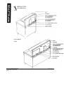
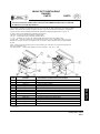
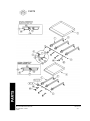
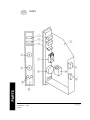
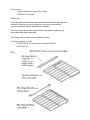
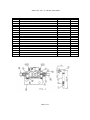
SHELF AND SPLASHER INSTALLATION
1.
Refer to the proper unit diagram.
2.
Place the splasher on the range as shown on the diagram.
3.
Tilt the splasher forward to allow the bottom flange to locate under the rear plate rest.
4.
Secure ends of splasher with four (4) 1/4-20 x 3/4 hex head bolts, flat washers and lockwashers (two (2) each end).
5.
Secure the splasher to the rear plate rest with # 10 x 1/2 sheet metal screws.
Four (4) on Models 300, 301 and 302. Five (5) on Models 303, 304, 320, 321, 322 and 323.
6.
323 Only: Secure splasher to the broiler-griddle area (just above the broiler-griddle fluing cutout in the splasher) with
three (3) # 10-24 x 1/2 machine screws, lockwashers and square nuts.
7.
303 and 304 Only: Secure the splasher heat shield with # 10 x 1/2 sheet metal screws.
Three (3) on Model 303. Four (4) on Model 304.
8.
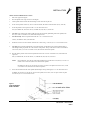
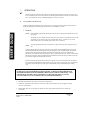
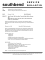
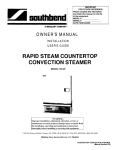
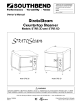
Install and secure the oven flue extensions with flue seal as shown in Fig. 1 with two (2) # 10 x 1/2 sheet metal screws.
9.
323 Only: Place the broiler-griddle flue box over the flue extension. Tilt the flue box out to allow the bottom flange to
slide through the fluing cut-out and rest on the front face of the splasher. The top of the flue box will be secured with the
same screws (three (3) # (10-24 x 1/2 machine screws) that secure the shelf to the splasher.
10.
Place the shelf in position on the front of the splasher and secure with # 10-24 x 1/2 machine screws, lockwashers and
square nuts.
Nine (9) on Models 300, 301 and 302. Eleven (11) on Models 303, 304, 320, 321, 322 and 323.
NOTE:
On the Model 323, secure the top of the broiler-griddle flue box with the same screws (three (3) # 10-24 x 1/2
machine screws of the eleven) that secure the shelf to the splasher.
On Models 303, 304, 320, 321, 322 and 323, secure the "Z" spacer to the splasher with center screw (# 10-24
x 1/2 machine screw) that secures the shelf to the splasher.
11.
Secure the wall shield to the ends of the splasher (double flange to the top) with eight (8) # 10 x 1/2 sheet metal screws.
On Models 303, 304, 320, 321, 322 and 323, also secure the splasher, at the center, to the "Z" spacer and the rear plate
rest with two (2) # 10 x 1/2 sheet metal screws.
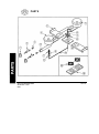
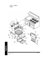
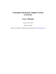
Figure 1
FLUE EXTENSION
WITH FLUE SEAL
HEAVY DUTY RESTAURANT RANGES
SECTION ONE — INSTALLATION
PAGE 5
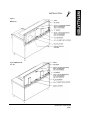
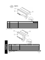
INSTALLATION
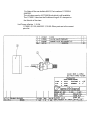
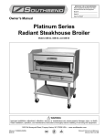
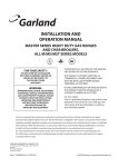
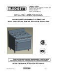
Figure 2 MODELS: 300,
301,302
Figure 3 MODELS:
303, 304
HEAVY DUTY RESTAURANT RANGES
SECTION ONE — INSTALLATION
Page 6
Litho in U.S.A.
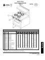
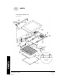
INSTALLATION
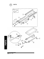
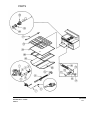
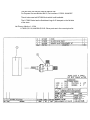
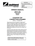
Figure 4
MODEL 323
Figure 5 MODELS 320,
321, 322
HEAVY DUTY RESTAURANT RANGES
SECTION ONE — INSTALLATION
PAGE 7
HEAVY DUTY
RESTAURANT RANGES
USER'S GUIDE
LIMITED WARRANTY
Southbend warrants that the equipment, as supplied by the factory to the original purchasers, is tree from defects in materials and
workmanship. Should any part thereof become defective as a result of normal use within the period and limits defined below, then at the option
of Southbend such parts will be repaired or replaced by Southbend or its Authorized Service Agency. This warranty is subject to the following
conditions:
If upon inspection by Southbend or its Authorized Service Agency it is determined that this equipment has not been used in an appropriate
manner, has been modified, has not been properly maintained, or has been subject to misuse or misapplication, neglect, abuse, accident,
damage during transit or delivery, fire, flood, riot or Act of God, then this warranty shall be void.
Specifically excluded under this warranty are claims relating to installation; examples are improper utility connections and improper utilities
supply. Claims relating to normal care and maintenance are also excluded; examples are calibration of controls, and adjustments to pilots and
burners.
Equipment failure caused by inadequate water quality is not covered under warranty. WATER QUALITY must not exceed the following limits:
Total Dissolved Solids (TDS) - 60 PPM (Parts Per Million). Hardness - 2 Grains or 35 PPM, PH Factor - 7.0 to 7.5. Water pressure 30 PSI
minimum, 60 PSI maximum. Boiler maintenance is the responsibility of the owner and is not covered by warranty.
This equipment is intended for commercial use only. Warranty is void if equipment is installed in other than commercial application.
Repairs under this warranty are to be performed only by a Southbend Authorized Service Agency. Southbend can not be responsible for
charges incurred from other than Authorized Southbend Agencies.
THIS WARRANTY MUST BE SHOWN TO AN AUTHORIZED SERVICE AGENCY WHEN REQUESTING IN-WARRANTY SERVICE WORK.
THE AUTHORIZED SERVICE AGENCY MAY AT HIS OPTION REQUIRE PROOF OF PURCHASE.
This warranty does not cover services performed at overtime or premium labor rates nor does Southbend assume any liability for extended
delays in replacing or repairing any items in the equipment beyond the control of Southbend. "Southbend shall not be liable for consequential or
special damages of any nature that may arise in connection with such product or part." Should service be required at times which normally
involve overtime or premium labor rates, the owner shall be charged for the difference between normal service rates and such premium rates.
In all circumstances, a maximum of one hundred miles in travel and two and one half hours (2.5) travel time shall be allowable. In all cases the
closest Southbend Authorized Agency must be used.
The actual warranty time periods and exceptions are as follows:
This warranty only covers product shipped into the 48 contiguous United States and Hawaii, one year labor, one year parts effective from the
date of original purchase. There will be no tabor coverage for equipment located on any island not connected by roadway to the mainland.
Exceptions to standard warranty, effective within above limitations:
Glass Windows, Door Gaskets, Rubber Seals, Light Bulbs, Ceramic Bricks,
Sight Glasses, Cathodic Descalers or Anodes ................................................................................................................ 90 days material and labor
Stainless Steel Fry Pot ............................................................................................ 4 years extended material warranty on fry pot only — no labor
Stainless Steel Open Top Burners ........................................................................ 4 years extended material warranty on burners only — no labor
Pressure Steam Boiler Shell ........................................................................... Prorated 4 years extended warranty on boiler shell only — no labor
Boiler shells which have not been properly maintained will not be covered by warranty.
In all cases parts covered by a five year warranty will be shipped FOB the factory after the first year. Our warranty on all replacement parts
which are replaced in the field by our Authorized Service Agencies will be limited to three months on labor, six months on materials (parts)
effective from the date of installation. See LIMITED WARRANTY - REPLACEMENT PARTS for conditions and limitations.
If the equipment has been changed, altered, modified or repaired by other than a qualified service technician during or after the one year limited
warranty period, then the manufacturer shall not be liable for any damages to any person or to any property which may result from the use of
the equipment thereafter.
"THE FOREGOING WARRANTY IS IN LIEU OF ANY AND ALL OTHER WARRANTIES EXPRESSED OR IMPLIED INCLUDING ANY
IMPLIED WARRANTY OF MERCHANTABILITY OR FITNESS, AND CONSTITUTES THE ENTIRE LIABILITY OF SOUTHBEND. IN NO
EVENT DOES THE LIMITED WARRANTY EXTEND BEYOND THE DURATION OF ONE YEAR FROM THE EFFECTIVE DATE OF SAID
WARRANTY."
HEAVY DUTY RESTAURANT RANGES
SECTION TWO — USER'S GUIDE
PAGE 1
OPERATION
WARNING:
FOR AN APPLIANCE EQUIPPED WITH CASTERS, THE INSTALLATION SHALL BE MADE
WITH A CONNECTOR THAT COMPLIES WITH THE STANDARD FOR CONNECTORS FOR
MOVABLE GAS APPLIANCES, ANSI Z21.69-1987, CAN1 6.10-88 AND A QUICK-DISCONNECT
DEVICE THAT COMPLIES WITH THE STANDARD FOR QUICK-DISCONNECT DEVICES FOR
USE WITH GAS FUEL, ANSI Z21.41-1978, AND ADDENDA, Z21.41a.1981, Z21.41b.1983 and CAN1
6.9 M79. ADEQUATE MEANS MUST BE PROVIDED TO LIMIT THE MOVEMENT OF THE
APPLIANCE WITHOUT DEPENDING ON THE CONNECTOR AND THE QUICK-DISCONNECT
DEVICE OR ITS ASSOCIATED PIPING TO LIMIT THE APPLIANCE MOVEMENT.
WARNING:
IF DISCONNECTION OF THIS RESTRAINT IS NECESSARY TO MOVE THE APPLIANCE FOR
CLEANING, ETC., RECONNECT IT WHEN THE APPLIANCE IS MOVED TO ITS ORIGINALLY
INSTALLED POSITION.
Before turning main gas supply on, make sure all control valves are in the "OFF" position.
All units are adjusted at the factory, however, burner air shutters and pilot heights should be checked at installation and adjusted
if necessary. On new installations start with the top burner of the unit(s) furthest from the gas input to the manifold. This will
purge the system of air. Turn main gas supply "ON."
OPEN TOP BURNER:
1. Remove pot support grates and enameled top plates.
2. Check lighter flash tubes to see they are properly positioned on burner charge port.
3. Light pilots.
4. Replace enameled plates and pot support grates.
5. Turn valve completely on. Burner flame should be steady blue and impinge on underside on pot placed on support grate.
TOP BURNER SECTIONS
OPTIONAL SOLID TOP PLATES - (Models - All 300 Series):
1. Raise or remove Hot Top plate. Every two burners has one pilot located at the front and in-between burners. Pilots are
supplied and adjusted by a valve, below a filter on the manifold.
2. Pilot flame should be steady blue, large enough to effect ignition.
3. Turn burner valve completely on. The sharp blue flame should be approximately 1/4" to 3/8" high.
4. Replace Hot Top plate.
FRY TOP GRIDDLES - (Models - 301, 302, 321, 322):
1. Raise griddle at front so it is approximately 8" high and block with two (2) two-by-fours.
2. Ignite pilot tube located under all burners with port at each side of burners. Pilots are supplied and adjusted by a common
valve located below the filter on the manifold.
3. Burners should have 1/2" to 5/8" steady blue flame. Adjust if necessary.
4. Lower griddle into position and observe burner operating characteristics through holes in valve panel.
CARE OF GRIDDLES:
New griddles should be carefully tempered and cared for in order to avoid possible damage. To break in a new griddle, first
wipe it clean. Next, light all the griddle burners and turn them low for one hour. Then gradually bring griddle to frying
temperatures. Next, spread three or four ounces of beef suet, or as a substitute baking soda, to season it. Never allow water on a
hot griddle and never wash it with soap and water.
HEAVY DUTY RESTAURANT RANGES
SECTION TWO — USER'S GUIDE
PAGE 2
Litho in
U.S.A. 4-92
OPERATION
THERMOSTAT GRIDDLES - (Models - T.301, T-302, T-321, T-322)
1.
Raise griddle at front so it is approximately 8" high and block with two (2) two-by-fours.
2.
The sensing bulbs must be fully inserted into their tubular holders, which are welded to the underside of the griddle.
3.
One pilot tube is located under all burners with ports at each side of burners. Pilots are supplied and adjusted by a
common valve on the manifold. Ignite pilots.
Set thermostat dials to maximum, one at a time.
Burners should have 1/2" to 5/8" steady blue flame. Adjust if necessary.
4.
5.
6.
Lower griddle carefully into position taking extreme care that capillary tubes are coiled under manifold in valve panel
compartment. NEVER leave any part of the capillary tube in the burner compartment.
7.
Observe burner flame through holes in valve panel, turn thermostat dial at maximum for ten minutes, then turn dial to
"LOW" and adjust bypass on thermostat so there is a 1/8" minimum and 1/4" maximum flame at each port. (See Fig. 2,
Section 3, Page 6).
BROILER GRIDDLES - (Models - 303,304, 323)
1.
2.
3.
4.
5.
6.
Remove griddle from unit.
Position ceramics on burners with projections pointing downward.
Light pilot tube ports (2 at each burner). Adjust pilot flame to be large enough to effect ignition.
Place griddle in position on range.
Turn valves completely on.
Burner should have 1/2" to 5/8" steady blue flame. Adjust if necessary.
7.
These valves are HI-LO type. HI flame is obtained by turning valve knob 90° to its horizontal position. LO or SIMMER
is obtained by continuing the rotation beyond its horizontal position. To adjust LO setting: remove knob, adjust set screw
inside hollow stem. The flame should be 1/8" to 1/4" on all ports.
CAUTION: TOP SECTION PILOTS WHEN OUT, DO NOT INTERRUPT THE FLOW OF
GAS TO THE BURNERS. CONSEQUENTLY, IT IS THE RESPONSIBILITY OF THE OPERATOR TO
CHECK THE IGNITION OF THE BURNERS, IMMEDIATELY AFTER BURNER VALVE HAS BEEN
TURNED TO "ON." SHOULD IGNITION FAIL AFTER 10 SECONDS, TURN OFF BURNERS, WAIT 5
MINUTES AND THEN TRY AGAIN.
RESTAURANT SERIES RANGES WITH AN "F" SUFFIX
("F" Suffix Denotes Type of Oven Control System)
WARNING:
IN THE EVENT OF MAIN BURNER IGNITION FAILURE, A 5 MINUTE PURGE PERIOD MUST BE
OBSERVED PRIOR TO RE-ESTABLISHING THE IGNITION SOURCE. IN THE EVENT A GAS ODOR IS
DETECTED, SHUT DOWN EQUIPMENT AT THE MAIN SHUTOFF VALVE AND CONTACT THE LOCAL
GAS COMPANY OR GAS SUPPLIER FOR SERVICE.
LIGHTING RANGE TOP PILOTS:
1.
Turn all valves to the "off" position.
2.
3.
Remove Top Plates to expose pilots.
Light Pilots - turn adjusting screw until a 1/2" pilot flame height is obtained.
LIGHTING OVEN:
1.
Turn thermostat to "off" position.
2.
Depress push button, light pilot (through hole in oven bottom or remove oven bottom). Hold button in for 30 seconds.
Release button. Should pilot fail to hold flame, wait 5 minutes and repeat.
Remove base panel. Remove pilot adjustment cap (on safety above push button). Adjust pilot key to provide properly
sized flame. Replace pilot adjustment cap.
Turn thermostat to desired temperature.
3.
4.
HEAVY DUTY RESTAURANT RANGES
SECTION TWO - USER'S GUIDE
PAGE 3
OPERATION
SHUTDOWN ENTIRE RANGE:
Standby:
1.
Turn all manual gas valve "off."
2.
Turn thermostat to its lowest position.
Complete:
1.
2.
Turn all manual gas valves and pilots "off."
Turn thermostat to its lowest position.
3.
Turn main supply gas valve "off."
STANDARD-TYPE OVEN - (Models 300, 301, 302, 303, 304, 320. 321, 322, 323)
A. LIGHTING:
1.
Turn oven thermostat to "OFF" position.
2.
Open door, raise hold-down clips at front of right and left sides, remove oven bottom and
fire plate to expose pilot and burner.
3.
Light constant pilot (i.e. pilot without capillary tube holder).
4.
Replace fire plate and oven bottom and lower hold-down clips.
5.
Turn thermostat to desired temperature.
NOTE: Lighting instructions are also printed on inside of oven door.
CAUTION: IF YOU SMELL GAS DURING THE LIGHTING PROCEDURE, IMMEDIATELY
SHUT OFF THE GAS SUPPLY UNTIL THE LEAK HAS BEEN CORRECTED.
B.
SHUT DOWN PROCEDURE:
To completely shut down the oven, turn thermostat to "OFF" position and extinguish pilot.
C.
RELIGHTING:
1.
Shut off all gas.
2.
Wait 5 minutes.
3.
Repeat lighting instructions in section "A" above.
STANDARD-TYPE OVENS (For Models With 'C' & 'B' Suffix Only):
The OVEN CONTROL system consists of an oven thermostat, a safety control and a pilot unit. The oven
thermostat is a combination modulating (by-pass type) thermostat for temperature settings above 325° F and a
cycling (on-off) thermostat for temperature settings from 140° F up to 325° F.
The safety control is a precision instrument carefully engineered and calibrated at the factory to control gas flow to
the Oven Burner. No adjustments are required.
The pilot unit has two separate pilots, a small Constant Pilot and a large Heater Pilot. The Constant Pilot, which
should be burning at all times, ignites the Heater Pilot when the thermostat is turned on and then the Oven Burner.
HEAVY DUTY RESTAURANT RANGES
SECTION TWO — USER'S GUIDE
PAGE 4
Litho in
U.S.A. 4-92
OPERATION
The thermostat is operated by the rotation of a single Control Knob for both the modulating and the low temperature ranges. To
operate, push Control Knob in and turn counterclockwise to desired temperature setting. To shut gas off, turn Control Knob
clockwise to "OFF" where it automatically will lock itself in the "OFF" position. If recalibration is ever necessary, it can be
done easily by following the instructions under that heading. However, cleaning the thermostat valve and regreasing the gas
valve should be done by a qualified serviceman if this work is required.
STANDARD-TYPE OVEN (Models With "D" Suffix Only):
The OVEN CONTROL system consists of an oven thermostat, a safety control and a pilot unit. The thermostat controls the oven
temperature by cycling the oven over the entire temperature range of 140° F to 500° F. This system has no bypass.
The safety control is a precision instrument carefully engineered and calibrated at the factory to control gas flow to the oven
burner. No adjustments are required.
The pilot unit has two separate pilots, a small Constant Pilot and a large Heater Pilot. The Constant Pilot, which should be
burning at all times, ignites the Heater Pilot when the thermostat is turned on. The Heater Pilot heats the capillary bulb allowing
the safety valve to open and feed gas to the burner.
CONVECTION-TYPE OVEN - (Models - CO-300, CO-301, CO-302, CO-303, CO-304,
CO-320, CO-321, CO-322, CO-323
WARNING:
FOR AN APPLIANCE EQUIPPED WITH A CONVECTION TYPE OVEN, NO ATTEMPT SHOULD BE MADE
TO OPERATE OVEN DURING A POWER FAILURE.
A.
CONTROL PANEL EXPLANATION (SEE FIG. 1 & 2, SECTION 4, PAGE 4)
1.
POWER SWITCH: In the "ON" position, power is made available to the thermostat, the pilot line solenoid and the
pilot spark igniter.
2.
FAN SWITCH: The fan switch controls the blower operation; it must be "ON" during baking or cooking periods.
In the "BAKE" position, the fan runs continuously, except when the door is open. This position is for baking or
cooking. In the "COOL" position, the fan runs continuously, even when the door is open. This position is for
cooling the oven at the end of a work period.
3.
THERMOSTAT AND COOKING LIGHT: The thermostat, by allowing power to the main gas solenoid,
controls the oven temperature. Setting the thermostat at a temperature greater than the oven temperature, energizes
the cooking light and the oven burner. Once the oven temperature is equal to or greater than the thermostat setting,
both the cooking light and the oven burner will shut off.
4.
TIMER: The timer is a mechanical, wind-up type. It is only a "time" reminder that has no control over the oven.
5.
FUSES: The motor and control circuitry are protected with two 15 AMP fuses in 208/236V convection ovens.
There are no fuses on 115 Volt units.
6.
ADDITIONAL UNIT CONTROLS (Double Oven Base Range Units Only): For long life of the control box
controls, a cooling blower has been incorporated into the design of the double oven base range units. This cooling
blower, which is located in the control compartment, is activated when the temperature inside of the control
compartment reaches 150° F at its sensing point. It will run continuously until the temperature drops below 135° F.
The cooling blower operates independent of the power switch of either oven, therefore, eliminating any controldamaging residual heat rise after the unit has been completely shut down.
HEAVY DUTY RESTAURANT RANGES
SECTION TWO — USER'S GUIDE
PAGE 5
OPERATION
For further protection of the control box controls if the cooling blower should happen to fail, the oven burners and
the oven circulating blower motors will shut down when the temperature inside the box housing the controls reaches
225° F at its sensing point. Refer to "TROUBLESHOOTING" in Section 3, Page 10.
B.
GAS CONTROL INSTRUCTIONS
All Heavy Duty Restaurant Ranges with convection-type oven are equipped, as standard, with electronic ignition for
lighting the standing pilot. The standing pilot, therefore, does not require lighting by a match.
1.
LIGHTING
NOTE:
Before attempting lighting of the standing pilot make sure the oven gas supply line shutoff valve is in the
open position.
The manual gas valve is located behind the chrome steel valve panel and is accessible thru the center slot.
The manual gas valve location is shown by an attached label. See Fig. 4, Section 4, Page 5 for the
location and the manner of accessibility of the manual valves on the EO-26.
NOTE:
The following lighting instructions are also printed on a plate located on the front panel below the oven
door.
To light the standing pilot, press the power switch to the "ON" position. Gas will immediately begin to flow to the
pilot and simultaneously, the electronic ignition will begin sparking at the pilot (an audible clicking noise should be
evident). When the pilot is ignited, the sparking and clicking noise should stop (this may be several minutes,
particularly in new installations where the gas lines may have a considerable amount of air). Within 30 to 60 seconds
after the pilot is ignited, the flame switch bulb will be heated sufficiently to allow the main gas solenoid to open and
the oven burner to light when the thermostat is turned on.
It should be noted that the standing pilot and the electronic ignition do not cycle with the thermostat. The standing
pilot is automatically established and monitored each time the power switch is on. If the pilot is ever extinguished by
a momentary external interruption, the spark igniter will automatically relight it without disturbing the cooking
cycle.
WARNING:
IN THE EVENT OF MAIN BURNER IGNITION FAILURE, A 5 MINUTE PURGE PERIOD MUST
BE OBSERVED PRIOR TO RE-ESTABISHING THE IGNITION SOURCE. IN THE EVENT A GAS
ODOR IS DETECTED, SHUT DOWN EQUIPMENT AT THE MAIN SHUTOFF VALVE AND
CONTACT THE LOCAL GAS COMPANY OR GAS SUPPLIER FOR SERVICE.
2.
STANDBY SHUTDOWN: Place the power switch in the "OFF" position.
3.
COMPLETE SHUTDOWN: Place the power switch in the "OFF" position and place the oven gas supply line shutoff
valve in the closed position.
4.
RELIGHTING: Place the oven gas supply line shutoff valve in the open position and place the power switch in the
"ON" position.
HEAVY DUTY RESTAURANT RANGES
SECTION TWO — USER'S GUIDE
PAGE 6
Litho in U.S.A.
4-92
OPERATION
C.
SPARK IGNITER FAILURE
In the event the spark igniter fails, the unit may still be operated by carefully following these instructions:
1.
Turn thermostat to the "OFF" position.
2.
Turn power switch to the "OFF" position.
3.
4.
WAIT A MINIMUM OF 5 MINUTES BEFORE PROCEEDING.
Turn power switch to the "ON" position.
5.
Immediately light pilot with a long match.
6.
After 30 to 60 seconds, the flame switch will allow the main oven burner gas to flow when the thermostat is turned
on.
IT IS INTENDED THAT THE OVEN BE OPERATED IN THE ABOVE MANNER ONLY IN EMERGENCY
SITUATIONS AND ONLY WHILE IT IS ATTENDED. DO NOT LEAVE THE PILOT LIT OVERNIGHT; SHUT OFF
THE POWER SWITCH. A QUALIFIED SERVICEMAN MUST BE CALLED PROMPTLY.
D.
NORMAL OPERATION
During normal daily operation, it is imperative that the oven fluing hole (2 inch dia.), located at the front of the oven
interior top, not be blocked off by any utensil used in the oven.
USER’S GUIDE
The pilot will now stay ignited as long as the power switch remains "ON." If the power switch is turned "OFF," repeat the
above instructions.
HEAVY DUTY RESTAURANT RANGES
SECTION TWO — USER'S GUIDE
PAGE 7
COOKING HINTS
COOKING TIPS (CONVECTION-TYPE OVEN ONLY):
A.
FROZEN ENTREE PRODUCTS: Punch holes in lid before heating. Tent lid if product has a tendency to stick, i.e.,
lasagne or macaroni and cheese. Use manufacturer's convection oven directions for time and temperature or reduce
conventional oven temperature 50 degrees for a 6-1/2 size pan load. Some products may cook in 10 to 15 minutes less
time than recommended for convection ovens if prepared from frozen in a 6 pan load.
B.
FRUIT PIES: Use temperature and time from manufacturer's directions for convection ovens for a 12 pie load placed on
3 bun pans.
C.
ROLLS - YEAST: Use temperature and time recommended by manufacturer for convection ovens for a 3 pan load.
D.
POTATOES - PRE-BLANCHED, FROZEN: Spread on ungreased bun pans, 3 pans per load. Bake at 400 degrees F,
stirring once, for 15 to 18 minutes.
E.
FISH PORTIONS - BREADED, PRE-COOKED: Use manufacturer's recommended temperature and time for
convection oven for a 3 pan load.
F.
POTATOES - BAKING, 8 OZ. SIZE: Wash and wrap in potato foil. Place 30 potatoes on 18 x 24 bun pan — 3 pans per
load. Bake in 400 degree F oven for 1 hour.
G.
TOP ROUND OF BEEF, NO. 168: Set oven at 250 degrees F. Place trimmed roast on pan. For 14 - 16 pounds: 140
degrees rare - 14 minutes/pound; 150 degrees medium - 16 minutes/pound; 160 degrees well done - 17-1/2
minutes/pound.
SUGGESTIONS (CONVECTION-TYPE OVEN ONLY):
If cakes are dark on the sides
and not done in the center .....................................................................................
If cake edges are too brown ..................................................................................
lower oven temperature.
reduce number of pans or lower
oven temperature.
If cakes have light outer color ............................................................................... raise temperature.
If cake settles slightly in the center ....................................................................... bake longer or raise oven
temperature slightly. Do not open
doors too often for long periods.
If pies have uneven color ......................................................................................
reduce number of pies per rack.
If meats are browned and not done in center ........................................................ lower oven temperature and roast
longer.
If meats are well done and not browned ...............................................................
raise temperature. Limit amount
of moisture.
If cake ripples ........................................................................................................
overloading pans or batter is too
thin.
If there is excessive meat shrinkage ...................................................................... lower oven temperature.
If cakes are too coarse ...........................................................................................
lower oven temperature
HEAVY DUTY RESTAURANT RANGES
SECTION TWO — USER'S GUIDE
PAGE 8
Litho in
U.S.A. 4-92
COOKING HINTS
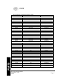
GUIDE TO BAKING TIMES AND TEMPERATURES (CONVECTION-TYPE OVEN ONLY):
As a guide, set oven temperatures 25 to 50 degrees lower than called for in recipes using non-convection ovens, i.e., range or
conventional ovens.
Time and temperatures will vary depending upon load, mix, size or portion and other factors. Use this chart to develop your own
cooking techniques.
PRODUCT
TIMING/
MIN.
TEMP. SETTING
NO. OF RACKS USED
COUNT PER
PAN/RACK
Hamburger buns, 3 oz. - 4"
18
375°
3
24
Yeast rolls - 1 oz.
10
400°
3
48
Fruit pies, 46 oz. frozen
50
375°
3
4
Egg custard pies, 44 oz. frozen
Dutch apple pies, 46 oz., frozen
60
325°
3
4
50
350°
3
4
Baked potatoes, 8 oz.
60
400°
3
30 (wrapped)
Pre-blanched potatoes, frozen
16
400°
3
5 lb.
16
400°
3
32
45
400°
3
2-6 lbs.
60
350°
3
2-6 lbs.
75
350°
3
2-6 lbs.
45
400°
3
2-6 lbs.
140° internal 14 min./lb.
250°
1
1-2
150° internal 16 min./lb.
250°
1
1-2
160° internal 17-1/2
min./lb.
250°
1
1-2
Fish portions, pre-cooked,
breaded, 3 oz.
Macaroni & cheese, 6 lb.
-40° temp.
Lasagne w/meat sauce, 6 lb.
- 40° temp.
Lasagne w/meat sauce,
6 lb. - frozen
Salisbury steak w/gravy, 6 lb.
- 40° temp.
Top round of beef No. 168
14 lb. - rare
14 lb. - medium
14 lb. - well done
WARNING:
THE USE OF ALUMINUM FOIL CAN CAUSE HEAT DISTRIBUTION PROBLEMS IN OVENS.
EXTREME CARE MUST BE USED WHEN PLACING ALUMINUM FOIL IN THE OVEN TO
ENSURE THAT IT DOES NOT BLOCK OR CHANGE THE AIR FLOW. THE USE OF ALUMINUM
FOIL MAY VOID THE PRODUCT WARRANTY IF ITS USE IS ASCERTAINED TO BE A
PROBLEM.
HEAVY DUTY RESTAURANT RANGES
SECTION TWO — USER'S GUIDE
PAGE 9
MAINTENANCE
WARNING:
ADJUSTMENTS AND SERVICE WORK MAY BE PERFORMED ONLY BY A QUALIFIED
TECHNICIAN WHO IS EXPERIENCED IN, AND KNOWLEDGEABLE WITH, THE OPERATION
OF COMMERCIAL GAS COOKING EQUIPMENT. HOWEVER, TO ASSURE YOUR
CONFIDENCE, CONTACT YOUR AUTHORIZED SERVICE AGENCY FOR RELIABLE
SERVICE, DEPENDABLE ADVICE OR OTHER ASSISTANCES, AND FOR GENUINE FACTORY
PARTS.
Southbend equipment is sturdily constructed of the best quality materials and is designed to provide durable service when
treated with ordinary care. To expect the best performance, your equipment must be maintained in good condition and cleaned
daily. Naturally, the periods for this care and cleaning depend on the amount and degree of usage.
MAINTENANCE-ALL UNITS-EXTERIOR AND TOP SECTIONS:
1.
Keep exposed, cleanable areas of unit clean at all times.
Daily:
A. Remove, empty, and clean grease drawers and dirt trays.
B. Clean griddle drain chutes.
Monthly:
A. Clean around burner air mixers and orifices if lint has accumula ted.
B. Visually assure proper pilot operation.
Vent System: At least twice a year the unit venting system should be examined and cleaned.
Following daily and periodic maintenance procedures will enhance long life for your equipment Climatic conditions— salt
air— may require more thorough and frequent cleaning or the life of the equipment could be adversely affected.
STAINLESS STEEL:
1.
To remove normal dirt, grease, and product residue from stainless steel that operates at LOW temperature, use ordinary
soap and water (with or without detergent) applied with a sponge or cloth. Dry thoroughly with a clean cloth.
2.
To remove grease and food splatter, or condensed vapors, that have BAKED on the equipment, apply cleanser to a damp
cloth or sponge and rub cleanser on the metal in the direction of the polishing lines on the metal. Rubbing cleanser, as
gently as possible, in the direction of the polished lines will not mar the finish of the stainless steel. NEVER RUB WITH
A CIRCULAR MOTION. Soil and burnt deposits which do not respond to the above procedure can usually be removed
by rubbing the surface with SCOTCH-BRITE scouring pads or STAINLESS scouring pads. DO NOT USE ORDINARY
STEEL WOOL, as any particles left on the surface will rust and further spoil the appearance of the finish. NEVER USE
A WIRE BRUSH, STEEL SCOURING PADS (EXCEPT STAINLESS), SCRAPER, FILE OR OTHER STEEL
TOOLS. Surfaces which are marred collect dirt more rapidly and become more difficult to clean. Marring also increases
the possibility of corrosive attack. Refinishing may then be required.
3.
To remove heat tint: Darkened areas sometimes appear on stainless steel surfaces where the area has been subjected to
excessive heat. These darkened areas are caused by thickening of the protective surface of the stainless steel and are not
harmful. Heat tint can normally be removed by the foregoing, but tint which does not respond to this procedure calls for
a vigorous scouring in the direction of the polish lines, using SCOTCH-BRITE scouring pads or a STAINLESS scouring
pad in combination with a powdered cleanser. Heat tint action may be lessened by not applying, or by reducing heat to
equipment during slack periods.
BLACK BAKED ENAMEL:
1.
Allow unit to cool somewhat after use and wash exterior with a hot, mild detergent or soap solution; particularly clean
off all grease deposits. Dry thoroughly with a dry cloth.
HEAVY DUTY RESTAURANT RANGES
SECTION TWO — USER'S GUIDE
PAGE 10
Litho in
U.S.A. 4-92
MAINTENANCE
BURNERS: General
Little attention is needed, but if spillage should occur, it may be necessary to clean around pilot areas, air mixer and under
burners. Use a wire brush if necessary.
Periodically, burners (particularly open top type) should be removed and cleaned. Allow interior to drain. Dry thoroughly before
replacing.
HOT TOPS:
Allow range to cool. If water is used on tops while still hot, they may crack. Avoid this practice. Remove tops from range and
clean surfaces with hot water and detergent. A wire brush may be used on the underside of the Hot Top plate. It is
recommended not to clean tops while still on range, even if cooled, as excessive water will drip into the burner box and
deteriorate the metal.
CARE OF GRIDDLES:
New griddles should be carefully tempered and cared for in order to avoid possible damage. To break in a new griddle, first
wipe it clean. Next, light all the griddle burners and turn them low for one hour. Then, gradually bring griddle to frying
temperature. Next, spread three or four ounces of beef suet, or as a substitute, baking soda, to season it. Never allow water on a
hot griddle and never wash it with soap and water.
Use a Norton Alundum Griddle Brick to clean the griddle. Always remember to heat griddle slowly because quick heat may
cause costly damage. Griddle plates cannot be guaranteed against damage due to carelessness. Never place utensils on griddle.
Do not overheat griddle above 550° F, as this will cause warpage or breakage.
Do not use any type of steel wool. Small particles may be left on the surface and get into food products. Do not clean spatula by
hitting the edge on the griddle plate. Such action will only cut and pit the griddle plate, leaving it rough and hard to clean.
Do not waste gas or abuse equipment by leaving valves at "Full On" position or thermostat at a high temperature if not required.
During idle periods, set valves at "Low" position or thermostats to low temperature settings to keep griddle warm. Reset valves
or thermostats, as required, for periods of heavy load. Turn valves or thermostats to "OFF" at end of daily operation.
OPEN TOP PLATE:
A.
Remove enameled top plate and spiders, clean with a solution of hot water and strong soap or detergent.
B.
The area around the charge port, where the flash tube is attached to the burner, must be free from any spillage or residue,
or other obstructions.
The flash tubes must be clean and properly aligned with the pilot housing to insure good top burner ignition. Pilot should
be 1/2" to 5/8" blue flame. Avoid carbon producing tip or unstable blowing or lifting of flame.
OVEN INTERIOR (STANDARD-TYPE OVEN ONLY):
Allow oven to cool. Remove porcelain enameled oven bottom. Clean by rubbing with strong detergent and Brillo pad or similar
scrubber. "Spill-overs" should be cleaned from the bottom as soon as possible to prevent carbonizing and a "burnt-on"
condition. For stubborn accumulations, commercial oven cleaners are recommended.
The porcelain oven door lining can be cleaned in a similar manner.
The side, rear and top lining should be wiped only with a cloth dampened with a mild detergent and water. Avoid using
excessive amounts of water, as this may drip into burner compartment and deteriorate the metal in that area. Do not use strong
commercial cleaners or abrasive pads on the side, rear or top linings, as they may damage the finish or leave gray residue.
HEAVY DUTY RESTAURANT RANGES
SECTION TWO — USER'S GUIDE
AGE 11
USER’S GUIDE
Do not waste gas and abuse equipment by leaving all burners "Full On," if not required. During idling periods, adjust burner
valves to keep top warm. Re-adjust burner valves as required for periods of heavy loads.
MAINTENANCE
OVEN INTERIOR (CONVECTION-TYPE OVEN ONLY):
WARNING
FOR YOUR SAFETY, DISCONNECT THE POWER SUPPLY TO THE APPLIANCE BEFORE
CLEANING.
Oven bottom and oven door lining are finished with a porcelain enamel coating which encourages frequent
cleaning. "Spill-overs" should be cleaned from the bottom or the door lining as soon as possible to prevent
carbonizing and a "burnt-on" condition. Usually, a soap or detergent solution is strong enough. For stubborn
accumulations, commercial oven cleaners are recommended.
The side, rear and top linings have an aluminized coating and should be cleaned with a sponge or cloth and a mild
detergent. Do not use a strong commercial cleaner or abrasive pad, as they may damage the finish.
The rack slides are readily removable for ease in cleaning. To remove, raise them and they will become disengaged
from their hanger studs. After cleaning reverse procedure to reinstall.
Foreign matter may collect on the blades of the blower wheel and reduce the circulation. When this becomes
apparent, remove the rear lining which is secured by thumb screws near each corner. Then, use a stiff brush on each
blade and finally, wash with soap and water. After cleaning reverse procedure to reinstall.
WHEN CLEANING THE BLOWER WHEEL, BE SURE TO HAVE THE POWER SWITCH IN THE "OFF"
POSITION.
CONTROL PANEL (CONVECTION-TYPE OVEN ONLY):
The textured control panel should be cleaned with warm water and mild soap. Never use cleaning solvents with a
hydrocarbon base.
MOTOR:
Lubrication information can be found on permanent label located on motor.
WARNING:
THE USE OF ALUMINUM FOIL CAN CAUSE HEAT DISTRIBUTION PROBLEMS IN OVENS.
EXTREME CARE MUST BE USED WHEN PLACING ALUMINUM FOIL IN THE OVEN TO
ENSURE THAT IT DOES NOT BLOCK OR CHANGE THE AIR FLOW. THE USE OF
ALUMINUM FOIL MAY VOID THE PRODUCT WARRANTY IF ITS USE IS ASCERTAINED TO
BE A PROBLEM.
HEAVY DUTY RESTAURANT RANGES
SECTION TWO — USER'S GUIDE
PAGE 12
Litho in
U.S.A. 4-92
ADJUSTMENTS
SERVICE
WARNING:
ADJUSTMENTS AND SERVICE WORK MAY BE PERFORMED ONLY BY A QUALIFIED
TECHNICIAN WHO IS EXPERIENCED IN, AND KNOWLEDGEABLE WITH, THE OPERATION
OF COMMERCIAL COOKING EQUIPMENT. HOWEVER, TO ASSURE YOUR CONFIDENCE,
CONTACT YOUR AUTHORIZED SERVICE AGENCY FOR RELIABLE SERVICE, DEPENDABLE
ADVICE OR OTHER ASSISTANCES, AND FOR GENUINE FACTORY PARTS.
In case of problems in operation at initial installation, check type of gas and manifold pressure and compare with information
listed on the serial plate.
FOR RESTAURANT RANGES WITH AN "F" SUFFIX
("F" Suffix Denotes Type of Oven Control System)
OVEN BURNER PILOT:
The pilot flame is adjustable at the pilot valve located at the manifold or at the pilot adjustment key located on the safety valve
adjacent to the red push button. To access the pilot key, remove the base panel, remove the pilot key cap and turn the adjusting
set screw. Replace pilot key cap.
THERMOSTAT BYPASS:
The thermostat is equipped with a bypass function. To adjust bypass flame, follow these steps:
1.
Be sure pilot is burning and properly adjusted.
2.
3.
Turn bypass adjusting screw (located on thermostat, visible when knob and bezel are removed) counterclockwise to full
open.
Turn thermostat dial to 500° F to ignite burner.
4.
After 5 minutes, turn dial to a position halfway between the 2 lines which are between "off" and "low."
5.
Remove the knob and turn the bypass adjusting screw clockwise until the flame on the oven burner is 1/8" minimum to
1/4" maximum and stable at each port on the burner.
THERMOSTAT CALIBRATION:
The thermostat should be recalibrated if the temperature at the center of the oven is not within 10° F of the dial setting (at 350°
F). If this condition exists, follow these steps:
1.
Do not attempt calibration until bypass flame is in proper adjustment.
2.
Remove the thermostat knob and with a screwdriver, pop out the knob's silver center insert, re-attach the knob to the
thermostat.
3.
Hold the dial firmly and insert a screwdriver through the center of the dial. Push the calibration screw inward (DO NOT
TURN THIS SCREW).
4.
While holding the calibration screw in and firm, turn the knob until the dial setting matches the actual oven temperature.
Replace the knob insert.
5.
Re-check calibration.
HEAVY DUTY RESTAURANT RANGES
SECTION THREE — SERVICE
PAGE 1
ADJUSTMENTS
TOP PILOTS: NON-AERATED (YELLOW-TIPPED FLAME) TYPE
These are located under fry-tops, hot-tops, broiler-griddles and on the flash tube system of open top grate burners.
Outage is often caused by an unstable flame due to over-adjustment to the point where the flame is leaving its port, or "blowing
off."
Often, in an effort to improve ignition, the pilots are increased too much and result in this unstable condition.
These pilots are adjusted by inserting the blade of a screwdriver into the slot on the small valve, located on the manifold. The
maximum flame size is approximately 3/4" with a slight yellow tip. The first indication of over-adjustment is evident when the
yellow tip begins to stream into black streaks and generate carbon. Continued over-adjustment leads to the unstable lifting and
blowing condition.
ALL TOP BURNERS:
All burners, being the Bunsen type, have a primary air adjustment by means of an air shutter on the mixer face.
Loosen screw and rotate mixer cap until a clear, stable blue flame is obtained. The flame should not be yellow tipped nor should
it blow off the burner ports.
All orifice sizes and burner rates are properly set at the factory and should not be altered.
Over-rated burners cause poor burner and pilot performance, resulting in less heat, and wasted gas.
Over-gased burners DO NOT heat the hot-top or griddle as efficiently as those that are properly adjusted. Such conditions also
create "hot spots" on griddles. Floating and unstable burner and pilot flames will result when solid tops are lowered into position
because the rear openings of the burner compartment are not adequate to vent the enormous flue products generated by overgased burners. The "unbumed" gas will ignite at the rear and burn in this section and even up inside the back-guard or shelf
venting system, causing structural members in this area to deteriorate. Also, some of these hot flue products will vent forward
into the manifold compartment resulting in problems with valves and thermostats due to overheating. AGAIN, over-rated
burners waste energy and cause service problems.
PRESSURE REGULATOR:
The pressure regulator is factory set at 4" W.C. for natural gas and 10" W.C. for propane gas. To check the manifold pressure:
1.
Turn all thermostats and burner valves to "OFF" position.
2.
Turn main gas valve to entire unit off.
3.
Remove valve panels and locate 1/8" plug in manifold.
4.
Remove plug and install a fitting appropriate to connect a manometer.
5.
Turn on main gas to unit and light pilots.
6.
Turn all burners and ovens to full "ON" position and read manometer.
7.
If manometer does not read 4" W.C. for natural gas, or 10" W.C. for propane gas, adjust regulator (if gas pressure is O.K.
go to Step 10).
8.
Remove cap from top of regulator.
9.
With a screwdriver rotate regulator adjustment screw "clockwise" to increase, or "counter-clockwise" to decrease,
pressure until manometer shows correct reading.
10.
Repeat steps 1 and 2.
11.
Remove manometer fitting and replace plug in manifold.
12.
Repeat step 5.
13.
Replace valve panels.
HEAVY DUTY RESTAURANT RANGES
SECTION THREE — SERVICE
PAGE 2
Litho in U.S.A.
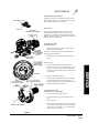
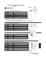
ADJUSTMENTS
STANDARD-TYPE OVEN ONLY
Because gas conditions vary in different localities, two basic
pilot adjustments for the OVEN system can be made to insure
proper operation when the range is installed.
PILOT UNIT
The two basic adjustments for the PILOT UNIT are the
Constant Pilot and the Heater Pilot. The gas flow to the
Constant Pilot is controlled by the Pilot Valve which is on the
Manifold. The Heater Pilot gas is controlled by the Heater Pilot
Adjusting Screw on the thermostat.
To Adjust These Pilots:
CONSTANT PILOT
1. Open Pilot Valve by turning screw counter-clockwise;
light Constant Pilot with match.
NOTE: The air must be bled from the line and Manifold in
order to light the Constant Pilot.
2. Adjust Pilot Valve for maximum flame without yellow
tipping.
HEATER PILOT
1. Turn Control Knob to the "DOT" position located
between the "OFF" and 140° F markings on the Control
Knob dial. This permits gas to flow through the Heater
Pilot Tube to the Heater Pilot where gas is ignited by the
Constant Pilot.
2. Remove Control Knob and Bezel.
3. Using screwdriver, adjust slotted Heater Pilot Adjusting
Screw until pilot flame just envelops Temperature
Responsive Element. Turning counterclockwise increases
the flame, turning clockwise reduces it.
To Adjust Bypass Flame:
(Units With 'B' & 'C' Suffix Only)
1. Be sure constant burning pilot is ignited.
2. Turn bypass adjuster (Fig. 1) counterclockwise to full
open.
3. Turn dial to 500° F.
4. After 5 minutes, turn dial to the "DOT" position between
"OFF" and 140° F, and adjust flame with bypass adjuster
so that it will be 1/8" minimum — 1/4" maximum steady
flame at each port on the burner.
Figure 1
HEAVY DUTY RESTAURANT RANGES
SECTION THREE — SERVICE
PAGE 3
ADJUSTMENTS
OVEN THERMOSTAT (STANDARD-TYPE OVEN ONLY)
To Recalibrate
This oven control is a precision instrument. It is carefully calibrated at the factory — that is, it is so adjusted that dial settings
match actual oven temperatures. Field recalibration is seldom necessary, and should not be resorted to unless considerable
experience with cooking results definitely proves that the control is not maintaining the temperatures to which the dial is set.
For units with 'B' and 'C' suffix, recalibration should not be undertaken until bypass oven flame has been adjusted. For units with
'D' suffix, no bypass exists.
To check oven temperatures when recalibrating, use a thermocouple temperature test instrument or a reliable mercury oven
thermometer. Place the thermocouple of test instrument, or the thermometer, in the middle of the oven.
The dial has a removable metal insert, proceed as follows:
1.
Remove dial and push out metal insert. (Fig. 1, Section 3, Page 3)
2.
Replace dial, set at 140° F and light oven burner.
NOTE:
3.
The oven burner will "snap" ON and OFF between the dial settings of 140° F and 325° F and no bypass flame
will be on the burner.
After burner has been on approximately 15 minutes, wait and watch for the oven burner to "snap" ON and then check
oven temperature. Oven door should be open for as short a time as possible. Use a flashlight, if necessary, to see the
thermometer reading clearly.
The control should be recalibrated if your reading is not within an average of 10° of the dial setting (140°). If recalibration is
required, the additional steps to be taken are these:
4.
Hold dial firmly, insert screwdriver through center of dial, and push calibration stem (See Fig. 1) inward. (DO NOT
TURN THIS STEM.)
5.
While holding calibration stem firmly, turn dial with screwdriver until it is set at the actual oven temperature as measured
by your test instrument or thermometer. Release pressure on calibration stem. Replace dial insert.
6.
To check your calibration setting, open door and allow oven to cool. Repeat steps 2 and 3. Recalibrate if necessary
following steps 4, 5 and 6.
NOTE:
If oven temperature continually "creeps" higher than the dial setting, this is an indication of an inoperative
sensing element or foreign matter on the valve disc or valve seat.
NOTE — Alternate Calibration Temperature Check
Calibration may be checked at 350° F (instead of 140° F). If this temperature is desired, remove dial and push out metal insert
(See Fig. 1, Section 3, Page 3).
A.
Replace dial, set a 350° mark and light oven burner.
B.
After burner has been on about 15 minutes, check oven temperature.
The control should be recalibrated if your reading is not within 10° of the dial setting (350°). If recalibration is required, proceed
as directed in steps 4 and 5; then recheck oven temperature at 400° F.
HEAVY DUTY RESTAURANT RANGES
SECTION THREE — SERVICE
PAGE 4
Litho in
U.S.A. 4-92
ADJUSTMENTS
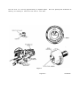
CONVECTION-TYPE OVEN ONLY:
A.
THERMOSTAT ADJUSTMENT: The calibration of the thermostat should not be changed until sufficient experience
with cooking results have definitely proved that the thermostat is not maintaining proper oven temperatures. Before any
recalibration is attempted, the oven temperature should be checked by the following procedure:
1.
The oven must be empty of all trays or pans.
2.
Place a pyrometer couple or a reliable mercury oven-type thermometer at the center of the middle rack.
3.
Turn on the blower.
4.
Set the dial at 375° F.
5.
The red "Cooking Light" will go out when the thermostat turns off the burners.
6.
Allow three such cycles for the temperature to stabilize.
7.
Read the pyrometer or thermostat immediately after the light goes out for the third time and again immediately after
it comes on the next time.
8.
If the average of these readings and the dial setting vary by more than 15°, recalibrate by following the instructions
outlined below:
TO RECALIBRATE:
NOTE:
Recalibration should be attempted only by a competent serviceman.
1.
Remove knob from dial shaft "B."
2.
Turn screw "A" clockwise to decrease and counterclockwise to increase temperature.
3.
1/4 turn changes the temperature 35° F.
4.
Replace knob on dial shaft.
5.
After the calibration is made, set the dial at 375° F and recheck the oven temperature using the method outlined by
Items 1 thru 7 of the oven temperature checking procedure.
B.
OVEN STANDING PILOT ADJUSTMENT: The standing oven pilot flame can be adjusted by turning the adjusting
screw on the pilot line valve with a screwdriver. The pilot line valve is located behind the front panel below the oven
door (See Fig. 3, Section 4, Page 5). Remove the front panel to gain accessibility. The pilot flame is properly adjusted
when it is just large enough to maintain a glowing red color of the flame switch capillary bulb.
C.
OVEN BURNER FLAME ADJUSTMENT: The oven burner orifice is of the fixed type, sized for the respective gas
supply. The burner flame characteristics are controlled by varying the primary air mixer cap. There should be a clear blue
flame with a distinct inner cone at each port. Excessive primary air can result in "blowing" or the flames leaving the
ports. Lack of primary air causes soft or yellow tipped flame.
HEAVY DUTY RESTAURANT RANGES
SECTION THREE — SERVICE
PAGE 5
ADJUSTMENTS
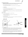
GRIDDLE CONTROL:
TO RECALIBRATE It is recommended that only a qualified serviceman perform this adjustment because calibration should not be changed unless
cooking results definitely prove the control is not maintaining the proper surface temperature.
DO NOT RECALIBRATE UNTIL THE FOLLOWING HAS BEEN CHECKED:
1.
BYPASS FLAME for proper adjustment (See "Thermostat Griddles" in Operation section).
2.
Check that the control bulb is fully inserted in the bulb tube.
Figure 2
TO CHECK CALIBRATION, PROCEED AS FOLLOWS:
USE A TEST INSTRUMENT with special "disc type" thermocouple or reliable "surface type" thermometer:
1.
2.
3.
4.
Check surface temperature of griddle by placing disc firmly in contact with griddle above sensing element (bulb) of
control. (NOTE — A drop of oil on face of disc will provide better contact).
Turn dial counterclockwise to 350° mark.
Heat griddle until control cuts down to BYPASS and check reading of Test Instrument. Reading of Test Instrument
should be between 335° F and 365° F.
If dial setting does not agree (within limits above) with Test Instrument reading, recalibrate as follows:
a.
b.
Remove dial.
Each division on calibration plate equals 25° F. With screwdriver, turn calibration screw clockwise (toward LO) to
reduce temperature, or counterclockwise (toward HI) to increase temperature.
Example:
c.
5.
Dial setting 350° mark. Test Instrument reading 380° F. Turn calibration screw clockwise (toward LO)
two divisions.
Replace dial, turning dia l to "OFF" position.
Repeat steps 1 through 3 to make sure correct adjustment has been made.
GRIDDLE THERMOSTAT BYPASS ADJUSTMENT:
1.
With pilots lit and properly adjusted, rotate thermostat dial counterclockwise to the 200° F setting to ignite the burners.
2.
Adjust air mixers for proper burner flame characteristics.
3.
4.
Heat thermostat capillary bulb by placing bulb in the oven with the oven burner on.
When griddle burners go out, rotate bypass adjustment screw counterclockwise until burners ignite.
5.
Adjust bypass flame by rotating adjustment screw clockwise until the flame length is approximately 1/8" to 1/4" long, is
stable, and not fluttering,
Turn off thermostat and remove capillary bulb from oven.
6.
HEAVY DUTY RESTAURANT RANGES
SECTION THREE — SERVICE
PAGE 6
Litho in U.S.A.
4-92
SERVICE
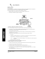
CONVECTION-TYPE OVEN ONLY:
WARNING:
BEFORE ATTEMPTING TO SERVICE OR REPLACE ANY ELECTRICAL COMPONENT, MAKE SURE
POWER SOURCE HAS BEEN DISCONNECTED.
CAUTION: WHEN CHANGING MOTOR OR SERVICING UNIT, ALWAYS VERIFY THAT
BLOWER WHEEL ROTATION IS AS ILLUSTRATION SHOWS. (CLOCK-WISE WHEN LOOKING INTO OVEN
CAVITY.
A.
MOTOR: The motor is serviceable from the front of the unit through the oven cavity. Remove the back lining.
Disconnect the motor mount plate by removing the eight hex nuts that secure it to the oven interior back. Pull the mount
plate, with motor attached, into the oven.
B.
CONTROL PANEL ASSEMBLY COMPONENTS (Single Oven Base Range Units. (See Fig. 1, Section 4, Page 4):
The control panel assembly components are easily serviceable by removing two screws (one at the top and one at the
bottom) of the control panel and then sliding out the control panel assembly.
C.
THERMOSTAT (Single Oven Base Range Units): After sliding out the control box assembly, the thermostat can be
completely removed by removing the capillary bulb brackets from inside of the oven, and then sliding the capillary bulb
out of the oven cavity into the unit control area.
D.
CONTROL BOX ASSEMBLY COMPONENTS (Double Oven Base Range Units (See Fig. 2, Section 4, Page 4):
The control box assembly components are easily serviceable by removing two screws (one at the top and one at the
bottom) of the control panel and then sliding out the control box. However, before attempting to slide out the control box,
follow the instructions on the "CAUTION" label attached to the unit lower front panel. The "CAUTION" label reads as
follows:
CAUTION: BEFORE SLIDING OUT CONTROL BOX FOR SERVICING, REMOVE
BASE PANELS BELOW OVEN DOOR AND REMOVE THE WIRE TIE FROM THE SPARK
IGNITER ELECTRODE WIRE (BLACK WIRE).
TO RETURN CONTROL BOX TO ORIGINAL POSITION, PUSH IN SLOWLY WHILE LIGHTLY
PULLING THE SPARK IGNITER WIRE (BLACK WIRE) INTO THE OVEN BURNER CONTROL
AREA (BELOW OVEN DOOR). RE-ATTACH A WIRE TIE IN A SIMILAR FASHION AS BEFORE
IT WAS REMOVED. REPLACE BASE PANELS.
After sliding out the control box, the controls are accessible by removing the control box cover.
E.
THERMOSTATS (Double Oven Base Range Units): To totally remove the thermostats after the control box has been
slid out as described in "D", further steps must be taken:
1. Remove the control box wiring strain relief stop located on the top of the control box.
2.
3.
4.
5.
Slide out the control box far enough to disconnect the wiring harness plugs.
Remove the thermostat capillary tie down brackets located in the control box.
Remove the upper air duct
Remove the capillary bulb brackets from inside of the ovens.
6.
Slide the capillary bulbs out of the oven cavity into the control box area between the two ovens for complete
removal.
HEAVY DUTY RESTAURANT RANGES
SECTION THREE - SERVICE
PAGE 7
SERVICE
F.
COOLING BLOWER: To service the cooling blower from the front of the unit follow the same steps as for removal of
the oven thermostats. After the oven thermostats have been removed, the control box assembly, complete with the cooling
blower, can be removed totally from the unit. To service the cooling blower from the rear of the unit, first, remove the
tubing side blower box cover. Second, remove the cooling blower box by removing four screws (two at the top and two at
the bottom) that secure it to the unit.
G.
208/236V 75VA TRANSFORMER (Double Oven Range Base Unit Only): The transformer is located in the cooling
blower box at the rear of the unit (See Fig. 2 & 5, Section 4, Pages 4 & 6) and is serviceable only from the rear of the
unit. To gain accessibility, remove either side cover of the blower box.
H.
FUSES: When replacing the fuses, the fuse should be inserted into the fuse holder cap FIRST and then into the fuse
holder by gripping the plastic top of the cap only. These steps should be done with caution by a qualified serviceman, as
the danger from severe electrical shock exists if the unit is not disconnected from the power supply.
NOTE:
When performing service work, the appropriate wiring diagram for your oven can be found at the rear of this
manual and also on the unit. The diagram on the single oven base range units is located on the rear of the lower
front panel. It can be accessed by removing the lower front panel.
The diagram on the double oven base range units is located on the inside of the control box cover. It can be accessed
by following the instructions for sliding out the control box assembly ("SERVICE" Paragraph D).
CAUTION: PROPER AND EFFICIENT OPERATION OF OVEN IS DEPENDENT ON
CORRECT INSTALLATION AND FUNCTION OF COMPONENTS. ALWAYS VERIFY THAT
COMPONENTS ARE IN PLACE AND FUNCTIONING AS INTENDED.
TROUBLE SHOOTING:
Problem
Look for —
All burners and pilots in unit will not turn
on
— Main gas supply to unit is "OFF."
All burners produce excessive carbon
deposits
— Incorrect gas type supplied to unit.
Only some burners in a unit produce
excessive carbon deposits
— Incorrect orifices.
— Incorrect supply pressure.
— Primary air not adjusted properly.
Only some pilots produce excessive carbon — Pilot gas not adjusted properly.
deposits
— Incorrect pilot orifice.
Top burner (not oven) will not come on
— Manual valve for top burner in "OFF" position.
— Pilot out.
Top section pilot will not stay ignited
— Pilot gas not adjusted properly.
— Clogged orifice.
— Draft condition.
— Improper ventilation system.
— Air in gas line.
HEAVY DUTY RESTAURANT RANGES
SECTION THREE — SERVICE
PAGE 8
Litho in U.S.A.
4-92
SERVICE
TROUBLE SHOOTING:
STANDARD-TYPE OVEN ONLY:
Problem
Look for —
Oven will not come on
— Oven pilot is out.
Oven pilot will not stay ignited
— Pilot gas not adjusted properly.
— Bad thermocouple. (Applies to units with D suffix only)
— Bad thermocouple connections at safety valve.
(Applies to units with D suffix only)
— Bad safety.
— Clogged orifice.
— Draft condition.
— Improper ventilation system.
— Air in gas line.
RESTAURANT RANGE STANDARD OVEN:
Oven will not come on
— Constant pilot is out.
— Heater pilot will not come on.
— Bad thermostat.
— Clogged burner orifice.
— Bad safety.
Constant pilot will not stay lit
— Clogged filter or pilot line.
— Clogged orifice.
— Draft condition.
— Improper ventilation system.
— Air in gas line.
Heater pilot will not come on
— Clogged orifice.
— Clogged pilot line.
— Bad thermostat.
HEAVY DUTY RESTAURANT RANGES
SECTION THREE — SERVICE
PAGE 9
SERVICE
TROUBLE SHOOTING:
CONVECTION-TYPE OVEN ONLY:
Problem
Check or Replace —
Unit does not come on when "Power Switch" is in the
"ON" position.
A.
B.
C.
D.
Is power cord plugged in?
Unit fuses.
Main supply fuses.
Unit power switch.
Motor will not run with fan switch in any position.
A.
B.
Fan switch.
Motor.
Motor will not run in "BAKE" position but runs in
"COOL" position.
A.
B.
Door switch actuator.
Door switch.
No spark at pilot.
A.
Spark igniter.
B.
Wire to spark electrode broken or disconnected.
Spark present but standing pilot will not light.
A.
B.
C.
D.
Gas supply to unit shut off.
Unit gas line shutoff in closed position.
Pilot line valve in closed position.
Pilot line solenoid.
Pilot ignites but burners will not light when thermostat
calls for heat. Cook light on.
A.
B.
C.
Main gas solenoid.
Flame switch bulb in correct position.
Flame switch.
Unit will function properly for a period of time and then
shut down (oven circulating blower and oven burners).
Oven will begin to function properly again after it has
cooled down.
A.
*B.
*C.
*D.
Motor overheating.
Check cooling blower.
Check 150 degree direct sensing thermostat.
Check 225 degree direct sensing thermostat.
*Double oven base units only.
Pilot ignites but burners and cook light will not come on
when thermostat calls for heat.
A.
Thermostat.
HEAVY DUTY RESTAURANT RANGES
SECTION THREE — SERVICE
PAGE 10
Litho in
U.S.A. 4-92
SERVICE
TROUBLE SHOOTING:
OVEN SECTION:
Problem
Look for —
Oven will not come on
— Oven pilot is out.
Oven pilot will not stay lit
— Pilot gas not adjusted properly.
— Bad safety thermocouple.
— Bad safety.
— Clogged pilot orifice.
— Draft condition.
— Air in gas line.
Oven temperature not controllable
— Improper oven burner bypass flame adjustment.
— Thermostat out of calibration.
Oven burner produces excessive carbon
deposits
— Incorrect type of gas supple d.
— Incorrect orifice size.
— Incorrect supply pressure.
— Primary air not adjusted properly.
Oven pilot produces excessive carbin
deposits
— Pilot gas not properly adjusted.
— Incorrect pilot orifice.
HEAVY DUTY RESTAURANT RANGES
SECTION THREE — SERVICE
PAGE 11
SERVICE
HEAVY DUTY RESTAURANT RANGES
SECTION THREE — SERVICE
PAGE 12
Litho in USA
SERVICE
HEAVY DUTY RESTAURANT RANGES
SECTION THREE — SERVICE
PAGE 13
SERVICE
HEAVY DUTY RESTAURANT RANGES
SECTION THREE — SERVICE
PAGE 14
Litho in U.S.A.
SERVICE
HEAVY DUTY RESTAURANT RANGES
SECTION THREE — SERVICE
PAGE 15
HEAVY DUTY RESTAURANT
RANGES
PARTS
PARTS
WARNING:
INSTALLATION OF OTHER THAN GENUINE SOUTHBEND PARTS WILL VOID THE
WARRANTY ON THIS EQUIPMENT.
The serial plate is located in the compartment below the oven on the right side. When ordering pans. please supply the Model
Number. Serial Number, Part Number, Description, plus Finish, Type of Gas and Electrical Characteristics, as applicable.
For parts not listed, consult a Southbend Authorized Pans Distributor or Southbend Authorized Service Agency. If
necessary, please consult Southbend Pans Department for assistance.
300 Series, "T" Prefix Unit has thermostatically controlled griddle.
"B" 1978 — Unit has tubular steel oven burners instead of cast iron.
"C" 1981 — On Models 323, 303, 304. only. Indicates griddle broiler burners have tabs welded on sides.
"D" Sept. 1982 — A change in thermostats, from a Robertshaw (with a by-pass) to a Robertshaw (without a by-pass)
BJFMAT. Oven burner is longer (23") compared to (20-1/4") for B & C units. Robertshaw safely has replaced Harper
Wyman.
NOTE: C & D units cannot interchange pans. Oven pilot bracket is pan of the burner. Oven pilot was Harper Wyman,
But is now Robertshaw #41 U.
First Serial Number — CO Base Range without Control Fuse 88J22722 — Mfg. Oct. 19, 1988.
PAGE NO.
RESTAURANT RANGE PARTS SECTION INDEX
1
2
3
4
5
6
7
8
9
10
*
*
Page 2
Page 3
Page 4, 5
Page 6, 7
Page 8, 9
Page 10,11
Page 12, 13
Page 14,15
Page 16,17
Page 18,19
Page 20, 21
Page 22
Shelfs and Splashers
Valve Panel and Base Panels
Open Top Burner Section
Optional Hot Top or 12" Wide Griddle
Griddle Section (thermostats optional)
Griddle Broiler Combination
Convection Oven Interior Oven Parts
Convection Oven Burner Compartment
Standard Oven Cooking & Burner Compartment
Double Convection Oven Control Panel
Single Convection Oven Control Panel
Conversion Kit
11
Page 23
PARTS
ITEM
Legs & Casters
* Not Shown
HEAVY DUTY RESTAURANT RANGES
SECTION FOUR — PARTS
PAGE 1
PARTS
ITEM
PART NO.
SHELF & SPLASHER 60-3/4" WIDE RANGE
1
1104214
Wall Shield
2
1000896
Splasher Weld asm SS 303-322
3
1167984
Shelf & Back Weld asm
4
1146304
Screw #10 x 1/2 Phil Truss Head
*
1000894
Splasher Weld asm SS
Models 303. 304.
320, 321, 322, 323
* Used on 323 & C0323 Only
ITEM
PART NO.
SHELF & SPLASHER 36-1/2" WIDE RANGE
1
1000898
Splasher Weld asm SS 300-302
2
1104216
Wall Shield
3
1167982
Shelf & Back Weld asm
4
1146304
Screw #10 x 1/2 Phil. Truss Head
Models 300 301.302
HEAVY DUTY RESTAURANT RANGES
SECTION FOUR — PARTS
PAGE 2
Litho in U.S.A.
3-93
HEAVY DUTY
RESTAURANT RANGES
PARTS
PARTS
RESTAURANT RANGE VALVE PANELS AND BASE PANELS
PARTS USAGE BY MODEL NUMBER
KEY PART
DESCRIPTION
#
NUMBER
1
1166995 Valve Panel
1162778
1162780
1162781
1162784
1162779
1162783
1162777
1162782
Valve Panel
Valve Panel
Valve Panel
Valve Pane!
Valve Panel
Valve Panel
Griddle Valve Panel
Valve Panel
2
*
*
3
*
*
*
1161633
1161634
1161635
1163896
1118805
1166277
1166279
Drip Pan 32-1/4" x 28"
Drip Pan 20-1/2" x 28"
Drip Pan 9-1/2" x 28"
Base Panel
Base Panel
Rt. Side Base Panel
Lt. Side Base Panel
USED ON 305 ONLY
1 1
1 1
1 1
1 1
1 1
1 1
1 1
1 1
1 1
1 1
1 1 1
1 1
1
1 1 1
PARTS
*
*
*
•
*
*
*
•
300
301
302
303
304
320
321
322
323
326
B DF B D F B D F B D F B D F B D F B DF B DF B D F B D F
1 1 1 1 1 1
1 1 1
1 1 1 1 1 1
1 1 1
1 1 1
1 1
1 1
1 1
1 1
1 1
1 1
1 1
1 1
1
1
1
1
1
1
1
1
USED ON ALL SINGLE CONVECTION OVENS & RT. SIDE OF DOUBLE CONVECTION OVENS
USED ON LEFT SIDE OF DOUBLE CONVECTION OVEN
* Not Shown
NOTE: All panels provided in stainless steel, black finish is no longer available.
NOTE: Model numbers with a "C" suffix will use same parts as the "D" suffix models.
HEAVY DUTY RESTAURANT RANGES
SECTION POUR — PARTS
PAGE 3
PARTS
HEAVY DUTY RESTAURANT RANGES
SECTION FOUR — PARTS
PAGE 4
Litho in
U.S.A. 3-93
HEAVY DUTY
RESTAURANT RANGES
PARTS
PARTS
RESTAURANT RANGE OPEN TOP BURNER
PARTS USAGE BY MODEL NUMBER
300
301
302
303
304
320
321
322
323
326
KEY
#
PART
NUMBER
1
1073496
Top Valve Knob
6 6 6 5 5 5 4 4 4 6 6 6 4 4 4 10 10 10 9 9 9 8 8 8 6 6 6
2
1164404
Valve Body
6 6 6 5 5 5 4 4 4 6 6 6 4 4 4 10 10 10 9 9 9 8 8 8 6 6 6
3
1008742
Burner Orifice NAT
6 6 6 5 5 5 4 4 4 6 6 6 4 4 4 10 10 10 9 9 9 8 8 8 6 6 6
4
1008755
1167387
Burner Orifice LP
Front Burner Stainless Steel
6 6 6 5 5 5 4 4 4 6 6 6 4 4 4 10 10 10 9 9 9 8 8 8 6 6 6
3
1
3
2
5
3
2
3
5
6
DESCRIPTION
B D F B D F B D F B D F B D F B
C50-00006 Rear Burner Stainless Steel
D15-00015 Burner Rest
3
1
3
D
2
F B D F B D F B D F B D F
5
3
2
3
1
C15-00016 Burner Rest
C15-00017 Burner Rest
1
1
1
C15-00018 Burner Rest
C15-00019 Burner Rest
1
1
1
1
7
1099002
Pilot Adj Valve
8
1099112
Pilot Ferrule
3
1
3
2
5
3
2
3
9
1099111
Pilot Nut
3
1
3
2
5
3
2
3
10
1146401
Pilot Mounting Nut
3
1
3
2
5
3
2
3
11
1167659
3
1
3
2
5
3
2
3
3
1
3
2
5
3
2
3
1
1
1
1
1
1
3
2
5
3
2
3
12
3 3 3 2 2 2 1 1 1 4 4 4 4 4 4 5
Pilot Cone
B39-00044 Pilot Mount
5
5 4 4 4 3 3 3 4 4 4
13
1174590
Pilot Tip
1
1
14
1174653
Pilot Supply Tube
3
1
4440364
Pilot asm Kit
15
1160162
Spider Grate (1126900)
6 6 6 2 2 2
6 6 6 4 4 4 10 10 10 6 6 6 4 4 4 6 6 6
16
1107596
Enameled Top Plate
3 3 3 1 1 1
3 3 3 2 2 2 5
17
+
CONSISTS OF ITEMS 8 THRU 13
A14-00032 Air Shutte
1163844
Oven Pilot Adj.
1
6
2
6
5
4
5 3 3 3 2 2 2 3 3 3
10
1 1 1 1 1 1 1 1 1 1 1 1 1 1 1 1
1
6
4
6
1 1 1 1 1 1 1 1 1 1
(P2168,1163927)
OLD STYLE CAST IRON OPEN TOP BURNER PARTS USED ON PRE 1988 MODEL RESTAURANT RANGES
*
1162932
Front Burner (Cast Iron)
3 3
1 1
3 3
2 2
5
5
3 3
2 2
3 3
*
1162930
Rear Burner (Cast Iron)
3 3
1 1
3 3
2 2
5
5
3 3
2 2
3 3
3 3
1 1
3 3
2 2
5
5
3 3
2 2
3 3
6 6
2 2
6 6
4 4
10 10
6 6
4 4
6 6
Charge Port
6 6
2 2
6 6
4 4
10 10
6 6
6 6
6 6
*
*
B42-00006 Top Pilot asm(P3103)
Flash Tube
P3100
*
1-5878
•
1008742
NAT Burner Orifice #42
6 6
2 2
6 6
4 4
10 10
6 6
4 4
4 4
*
1008755
LP Burner Orifice #55
6 6
2 2
6 6
4 4
10 10
6 6
4 4I
6 6
* Old style cast iron open top burner pans not shown on diagram used on unit prior to 1988.
+ Not shown on diagram.
NOTE: Model numbers with a "C" suffix will use same parts as the "D" suffix models.
HEAVY DUTY RESTAURANT RANGES
SECTION FOUR — PARTS
PAGE 5
PARTS
HEAVY DUTY RESTAURANT RANGES
SECTION FOUR — PARTS
PAGE 6
HEAVY DUTY
RESTAURANT RANGES
PARTS
PARTS
HOT TOP SECTION "OPTIONAL" (each Hot Top replaces 2 Open Burners) See Figure
PARTS USAGE BY MODEL NUMBER
KEY
#
PART
NUMBER
DESCRIPTION
300
301
302
303
304
320
321
322
323
326
1
2
1073496
1164404
Valve Knob
On-Off Valve
B D F B D F B D F B D F B D F B D F B D F B D F B D F B D F
————————————— 2 PER SECTION ———————————
————————————— 2 PER SECTION ———————————
3
1008942
Hood Orifice NAT
————————————— 2 PER SECTION ———————————
1078955
Hood Orifice LP
————————————— 2 PER SECTION ———————————
4
5
1022994
1099002
Hot Top Burner
Filter & Valve
————————————— 2 PER SECTION ———————————
————————————— 1 PER SECTION ———————————
6
1099100
1/8 cc Nut
————————————— 1 PER SECTION ———————————
7
1170417
Aeration Box
————————————— 1 PER SECTION ———————————
8
1099101
1/8 Reduction Ferrule
————————————— 1 PER SECTION ———————————
9
10
3346
1160410
Pilot Tube
Pilot asm
————————————— 1 PER SECTION ———————————
————————————— 1 PER SECTION ———————————
11
3435
Pilot Brkt
————————————— 1 PER SECTION ———————————
12
3448
Burner Support
————————————— 1 PER SECTION ———————————
13
1112299
Top Plate asm
————————————— 1 PER SECTION ———————————
12" WIDE GRIDDLE SECTION "OPTIONAL" (each Griddle Replaces 2 Open Burners) See Figure
PARTS USAGE BY MODEL NUMBER
300
301
302
303
304
320
321
322
323
326
KEY
#
PART
NUMBER
14
1099002
Pilot Adj. Valve
B D F B D F B D F B D F B D F B D F B D F BD F B D F B D F
————————————— 1 PER SECTION ———————————
15
1099112
Ferrule 1/4 inch
————————————— 1 PER SECTION ———————————
16
17
1099111
1162236
1/4 cc Nut
Pilot Tube
————————————— 1 PER SECTION ———————————
————————————— 1 PER SECTION ———————————
18
1099111
1/4 cc Nut
————————————— 1 PER SECTION ———————————
19
20
1099112
P3875
Ferrule 1/4 inch
Straight Fitting
————————————— 1 PER SECTION ———————————
————————————— 1 PER SECTION ———————————
21
1162808
Griddle Pilot Tube
————————————— 1 PER SECTION ———————————
22
23
1171902
1042980
Bar Burner Rt.
Bar Burner Lt.
————————————— 1 PER SECTION ———————————
————————————— 1 PER SECTION ———————————
24
1162667
Griddle asm 12 inch
————————————— 1 PER SECTION ———————————
•
1160960
Grease Drawer asm
————————————— 1 PER SECTION ———————————
-
1008748
Orifice NAT Gas
————————————— 2 PER SECTION ———————————
*
1008756
Orifice LP Gas
————————————— 2 PER SECTION ———————————
DESCRIPTION
PARTS
* Not Shown on drawing NOTE: Model numbers with a "C" suffix will use same parts as the
"D" suffix models.
HEAVY DUTY RESTAURANT RANGES
SECTION FOUR — PARTS
PAGE 7
PARTS
HEAVY DUTY RESTAURANT RANGES
SECTION FOUR — PARTS
PAGE 8
Litho in U.S.A.
3-93
HEAVY DUTY
RESTAURANT RANGES
PARTS
PARTS
RESTAURANT RANGE STANDARD & THERMOSTATIC GRIDDLE (Indicated by T-Prefix)
PARTS USAGE BY MODEL NUMBER
300
301
302
303
304
320
321
322
323
KEY
#
PART
NUMBER
1
1042980
Griddle Bar Burner
3 3 3 4 4 4
3 3 3 4 4 4
2
1134810
Burner Support
3 3 3 4 4 4
3 3 3 4 4 4
3
1174708
Griddle asm (1009197)
1009198
Griddle asm
4
1162980
Griddle Pilot
5
1162828
Griddle Pilot
1 1 1
1 1 1
6
1099002
Pilot Adj. Valve
1 1 1 1 1 1
1 1 1 1 1 1
7
1099112
1/4 Ferrule
1 1 1 1 1 1
1 1 1 1 1 1
8
1099111
1/4 cc Nut
1 1 1 1 1 1
1 1 1 1 1 1
9
1162236
Pilot Tube
1 1 1 1 1 1
1 1 1 1 1 1
10
1099111
1/4 cc Nut
1 1 1 1 1 1
1 1 1 1 1 1
11
P3875
1/8 x 1/4 Straight Fitting
1 1 1 1 1 1
1 1 1 1 1 1
12
1146906
90° Elbow
1 1 1 1 1 1
1 1 1 1 1 1
+13
1020401
Thermostat Knob
1 1 1 2 2 2
1 1 1 2 2 2
+14
1020400
Thermostat Only
1 1 1 2 2 2
1 1 1 2 2 2
+15
1127702
Orifice Tee NAT
2 2 2 2 2 2
+
1127703
Orifice Tee LP
+16
1115400
Gas Supply Tube
2 2 2 2 2 2
2 2; 2 2 2 2
;
2 2 2
+17
P9265
Brass Tee
1 1 1
+18
1115401
DESCRIPTION
326
B D F B D F B D F B D F B D F B D F B D F B D F B D F B D F
1 1 1
1 1 1
1 1 1
1 1 1
1 1 1
Gas Supply Tube
1 1 1
2 2 2 2 2 2
1
2 2 2
1 1 1
2 2 2
Brass Elbow
2 2 2
P4119
2 2 2
2 2 2
20
1164404
Valve Body Only
3 3 3 4 4 4
3 3 3 4 4 4
21
1073496
Griddle Knob
3 3 3 4 4 4
3 3 3 4 4 4
*
1008748
Griddle Orifice NAT
3
4
3
4
*
1008756
Griddle Orifice LP
3
4
3
4
*
1160960
Grease Drawer (1160917)
1 1 1 1 1 1 (25L x 3-1/2W x 3-3/4H)
PARTS
+19
1 1 1 1 1 1
+ These parts are optional and used on Ranges with Thermostatically controlled griddles only, as indicated by T Prefix.
* Part not shown on drawings.
NOTE: Model numbers with a "C" suffix will use same parts as the "D" suffix models.
HEAVY DUTY RESTAURANT RANGES
SECTION FOUR — PARTS
PAGE 9
PARTS
NOTE: ADDITIONAL BURNER & PILOT
FOR 304 ONLY
HEAVY DUTY RESTAURANT RANGES
SECTION POUR — PARTS
PAGE 10
Litho in U.S.A
3-93
HEAVY DUTY
RESTAURANT RANGES
PARTS
PARTS
GRIDDLE SECTION
PARTS USAGE BY MODEL NUMBER
KEY
#
PART
NUMBER
1
1161636
Broiler Dirt Tray
2
2
1173555
3136
Broiler Rack Pan
1 1 1 1 1 1
1 1 1
Rack Pan Broiler (Prior to 9/2/91)
1 1
1 1
3
1099111
1/4 cc Nut
1 1 1 2 2 2
1 1 1
4
1099112
1/4 Ferrule
1 1 1 2 2 2
1 1 1
5
P3875
1/8 x 1/4 Straight Fitting
1 1 1 2 2 2
1 1 1
6
1133999
Griddle Pilot
1 1 1 1 1 1
1 1 1
7
1163187
Gas Supply Tube
1 1 1 1 1 1
7
8
1162935
P3112
9
3240
Gas Supply Tube
Ceramic (center)
6-9/16 x 7-1/2 x 1/2
Rear Burner Support
4 4 4 4 4 4
1 1 1 1 1 1
4 4 4
1 1 1
10
1030200
Burner Rest Brkt
2 2 2 2 2 2
2 2 2
11
1042997
Broiler Burner (side)
2 2 2 2 2 2
12
1042996
Broiler Burner (center)
1 1 1 1 1 1
*
1162994
Broiler Burner (side)
*
1162995
Broiler Burner (center)
13
1109199
Griddle Plate
•
14
1009197
P3111
Griddle Plate
15
DESCRIPTION
300
301
302
303
304
320
321
322
323
326
B D F B D F B D F B D F B D F B D F B D F B D F B D F B D F
1 1 1 1 1 1
1 1 1
1 1
1 1 1
I
2 2 2
1 1 1
1 1 1
1 1 1
1 1 1
Ceramic (side)
3-1/2 x 7-1/2 x 1/2
4 4 4 4 4 4
4 4 4
1126802
Broiler Valve
3 3 3 3 3 3
3 3 3
16
1146304
Screw #10 x 1/2 Phil
4 4 4 4 4 4
4 4 4
17
1073495
Broiler Valve Handle
3 3 3 3 3 3
3 3 3
18
P2133
Pilot Adj. Valve
1 1 1 2 2 2
1 1 1
19
1099112
1/4 Ferrule
1 1 1 2 2 2
1 1 1
20
1099111
1/4 Nut
1 1 1 2 2 2
1 1 1
21
1173556
Brioler Rack Support
1173554
Broiler Rack
22
Rack Broiler (prior to 9/2/91)
4
4
4
1
1 1
1 1
1 1
22
P3090
23
1162334
Griddle Pilot
1 1 1
1042980
Griddle Burner
1 1 1
*
1160979
*
1008751
Grease Draw (1160978) (24L x 3-3/8W x 3-3/4H)
Broiler Burner Orifice RT & LT NAT
1 1 1
2 2 2 2 2 2
•
1008753
Broiler Burner Orifice Center NAT
1 1 1 1 1 1
*
1008749
Broiler Burner Orifice RT & LT NAT
*
1008757
Broiler Burner Orifice RT & LT LP
2 2 2 2 2 2
2 2 2
*
1008765
Broiler Burner Orifice Center LP
1 1 1 1 1 1
1 1 1
24
1 1 1
2 2 2
* Not Shown on drawing NOTE: Model numbers with a "C" suffix will use same parts as
HEAVY DUTY RESTAURANT RANGES
SECTION FOUR — PARTS
PAGE 11
PARTS
the "D" suffix models.
PARTS
HEAVY DUTY RESTAURANT RANGES
SECTION FOUR — PARTS
PAGE 12
Litho in U.S.A.
3-93
HEAVY DUTY
RESTAURANT RANGES
PARTS
PARTS
RESTAURANT RANGE CONVECTION OVEN INTERIOR PARTS
KEY#
PART NO.
DESCRIPTION
1
4440300
Motor Kit (115-208-240V) 1/4 HP (1165771, 1165898, 1166085, 1170126)
2
1161799
Motor Mount Bracket
3
1165957
Motor Mount Bolt asm
4
1165959
Motor Mount Pocket asm
5
1165521
Blower Wheel
6
1166993
Motor Spacer
7
1173466
Rear Air Baffle (1165953)
8
1160289
Thumb Screw 1/4 - 20 x 3/4
9
1168169
Enameled Oven Bottom (after July 85)
1165692
Oven Bottom (prior to July 85)
10
1165732
Rack Guide
*
1165652
Oven Rack (18 x 25-13/16)
11
4440000
Oven Door Handle Kit (Includes Screw 1/4 x 20 x 2)
12
1168189
Left Hand Door Hinge Pin asm (after 7-11 -85) 1168187
1165909
Left Hand Door Hinge Pin asm (before 7-11-85)
13
1168190
Right Hand Door Hinge Pin asm (after 7-11 -85) 1168188
1165910
Right Hand Hinge Pin asm (before 7-11-85)j15
+14
1168208
Oven Door (stainless steel) 1165904
15
1165956
Oven Door Seal (top and bottom) 1165907
16
1165955
Oven Door Seal (sides)
17
1165763
Top Seal Retainer
18
1165764
Side Seal Retainer
19
1166106
Bottom Seal Retainer
20
1666107
Bottom Splash Guard
21
1166100
Oven Fire Plate
22
1166099
Right Burner Box Shield
23
1166098
Left Burner Box Shield
*
1165702
Spring Plunger (door latch)
•
1165906
Spring Plunger Catch (door latch)
*
1160205
Pressure regulator (NAT) (1160164)
1160206
Pressure Regulator (LP) (1160173)
1168188
Door Stake Right
*
1168187
Door Stake Left (not shown)
*
1165111
Wire Screen For Air Baffle
25
1118302
Oven Bottom Gasket Sea! (sells per ft.)
*
1170038
Tape 1" Double Face (Hold bottom gasket seal in place)
PARTS
*
24
• Not shown on drawing.
+ Note: Black doors are no longer available - stainless steel is now supplied
HEAVY DUTY RESTAURANT RANGES
SECTION FOUR — PARTS
PAGE 13
PARTS
HEAVY DUTY RESTAURANT RANGES
SECTION FOUR — PARTS
PAGE 14
Litho in U.S.A
3-93
HEAVY DUTY
RESTAURANT RANGES
PARTS
PARTS
RESTAURANT RANGE STANDARD OVEN PARTS
PARTS USAGE BY MODEL NUMBER
PART
NUMBER
1
1
1
1
2
3
4
4
1164037
1161740
1168288
1168289
1147114
1057200
1008736
1008752
4
4
5
6
1008742
1008753
1161048
A58-00006
7
8
19
20
1163868
1163869
1163870
1013698
1164282
1164125
1161138
1164255
1160999
1119201
1009000
1161748
1034900
1034901
1119099
P1089
1173547
1000315
1173545CP
1107898
1168286
20
20
21
22
*
23
24
25
1167432
1167004
1160986
1160987
1164289
A32-00012
1013004
B9400001-01
8
8
9
9
9
10
11
12
13
14
15
16
17
18
DESCRIPTION
Safety Valve
Safety Valve
Safety Valve (1164281 )NAT
Safety Valve (1164280) LP
Hex Head Reducer 1/2 x 1/8
Orifice Fitting
Oven Orifice NAT #36
Oven Orifice LP #52
Oven Orifice (NAT #42)
Oven Orifice (LP #53)
Brass Street Elbow
Orifice Extension
Thermocouple
Oven Pilot (NAT)
Oven Pilot (LP)
Oven Pilot
Oven Orifice (LP #53)
Oven Burner
Oven Burner
Oven Burner
Burner Support
Quadrant Bolt
Quad Brkt Top
Quadrant Spacer
Door Spring Hook LT
Door Spring Hook RT
Quad & Bush Assy
Door Spring
Oven Rack Support
Oven Rack
Oven Rack
Oven Bottom
Fire Plate asm
Fire Plate asm (prior 7/84)
Fire Plate asm (after 7/84)
Combustion Chamber LT
Combustion Chamber RT
Pilot Shield
Knob
Bezel
Thermostat 36" Cap.
300
301
302
303
304
320
321
322
323
326
B D F B D F B D F B D F B D F B D F B D F B D F B D F B D F
1
1
1
1
1
2
2
2
2
1
1
1
1
1
1
1
1
1
1
1
1
1
1
2
2
2
2
1
1
1
1
1
2
2
2
2
1
1
1
1
1
2
2
2
2
1
1
1
1
1
2
2
2
2
1
1
1
1
1
2
2
2
1
1
1
1
1
2
2
2
2
1 1
1 1
1 1
1 1
1 1
1 1
1 1
1 1
1 1
1 1
2 2
2 2
2 2
2 2
2 2
2 2
2 2
2 2
1
1
1
1
1
1
1
1
1
1
2
2
2
2
2
2
2
2
1
1
1
1
1
1
1
1
1
1
1
1
1
1
1
2
2
2
2
2
2
2
2
2
2
2
2
1
1
1
1
1
1
1
1
1
1
1
1
1
1
1
1
1
1
1
1
1
1
1
1
1
2
1
1
1
2
1
1
2
1
2
1
1
1
1
1
1
1
1
1
1
1
1
1
1
1
2
2
2
2
2 2 2 2 2 2 2 2 2 2 2 2 2 2 2 4 4 4 4 4 4 4 4 4 4 4 4
2 2 2 2 2 2 2 2 2 2 2 2 2 2 2 4 4 4 4 4 4 4 4 4 4 4 .
2 2 2 2 2 2 2 2 2 2 2 2 2 2 2 4 4 4 4 4 4 4 4 4 4 4 4,
1 1 1 1 1 1 1 1 1 1 1 1 1 1 1 2 2 2 2 2 2 2 ,2 2 2 2 4
2
1 1 1 1 1 1 1 1 1 1 1 1 1 1 1 2 2 2 2 2 2 2 2 2 2 2 2
2 2 2 2 2 2 2 2 2 2 2 2 2 2 2 4 4 4 4 4 4 4 .4 4 4 4 4
2 2 2 2 2 2 2 2 2 2 2 2 2 2 2 4 4 4 4 4 4 4 4 4 4 4 4
4
4
4
4
4
8
8
8
8
————————— RACK USED PRIOR TO NOVEMBER 1991 ————
————————— RACK USED AFTER TO NOVEMBER 1991 ————
1 1 1 1 1 1 1 1 1 1 1 1 1 1 1 2 2 2 2 2 2 2 2 2 2 2 2
1
1
1
1
1
2
2
2
2
1 1
1 1
1 1
1 1
1
1
1 1
1 1
1
1
1 1
1 1
1
1
1 1
1 1
1
1
1 1
1 1
1
1
1 1
1 1
2
2
1 1
;
1 1
2
2
1 1
1 1
2
2
2
2
1
1
1
1
1
1
1
1
1
1
1
1
1
1
2
2
2
2
1 1 1 1 1 1 1 1 1 1 1 1 1 1 1 2 2 2 2 2 2 2 2 2 2 2 2 2 2
1
1
1
1
1
2
2
2
2
1
B9400001-02 Thermostat 60" Cap.
1
PARTS BELOW ARE USED AS REPLACEMENT KITS ON UNITS BUILT PRIOR TO JANUARY 1988
*
A81-00054
Thermostat 36" Cap.
1 1
*
*
*
A81-00055
1013003
1013004
Thermostat 60" Cap.
1 1
1 1
1 1
1 1
1 1
1 1
2 2
2 2
2 2
2 2
2 2
1 1 1 1 1 1 1 1 1 1 1 1 1 1 1 2 2 2 2 2 2 2 2 2 2 2 2 2 2
Knob
Bezel
1 1
1 1
1 1
1 1
2 2
2 2
2 2
2 2
1 1
* Not Shown on drawing
HEAVY DUTY RESTAURANT RANGES
SECTION FOUR — PARTS
PAGE 15
PARTS
KEY
#
PARTS
HEAVY DUTY RESTAURANT RANGES
SECTION FOUR — PARTS
PAGE 16
Litho in U.S.A.
3-93
HEAVY DUTY
RESTAURANT RANGES
PARTS
PARTS
CONVECTION OVEN BASE RESTAURANT RANGE BURNER COMPARTMENT
KEY #
PART NO.
DESCRIPTION
1
1165781
Bolt 3/8 x 16 x 4 (for door sprocket)
2
1165796
Sprocket asm Brkt
3
1165783
Door Sprocket Bushing
4
1166129
Door Chain Pully
5
1165905
Oven Door Chain asm
6
1165756
Oven Door Spring
7
1168300
Door Switch asm (used on single oven & right side of double ovens)
•
1165942
Door Switch asm (used on left oven of double oven)
8
1142000
Door Switch
9
1165733
Oven Burner
•
1166135
Left Oven Pilot Tube
10
1165510
Dual Solenoid Valve
11
1165512
Pilot Valve
12
1164807
Spark Electrode
13
1166136
Pilot Tube (right oven)
14
1166761
Orifice Bracket
15
1148306
Fitting, Orifice Body, For Hood
*
1008742
Oven Burner Orifice (NAT #42)
*
1008753
Oven Burner Orifice (LP #53)
16
1165708
Flame Switch Mounting Bracket
+17
1168262
Flame Switch (1164805)
+18
1168263
Oven Pilot (1165734)
19
1165767
Pilot Shield
20
1166139
Orifice Tube Right and Left
* Not shown on drawing.
HEAVY DUTY RESTAURANT RANGES
SECTION FOUR — PARTS
PAGE 17
PARTS
+ If replacing either flame switch or oven pilot on Restaurant Range built before Dec. 1985 use 4440299 Pilot and
Flame Switch Kit to convert to current style Pilot & Flame Switch. Old & New Parts will not interchange.
PARTS
HEAVY DUTY RESTAURANT RANGES
SECTION FOUR — PARTS
PAGE 18
Litho in U.S.A
3-93
HEAVY DUTY
RESTAURANT RANGES
PARTS
PARTS
DOUBLE CONVECTION OVEN BASE RESTAURANT RANGE CONTROL PANEL
KEY#
PART NO.
DESCRIPTION
1
1164503
Power Switch (Left Oven)
2
1164504
Fan Switch (Left Oven)
3
1161450
Neon Bulb, Red Lens, 125V
4
1166079
Thermostat Dial (Left Oven)
5
1173542
Thermostat (Left Oven)
6
1164503
Power Switch (Right Oven)
7
1164504
Fan Switch (Right Oven)
8
1161450
Neon Bulb, Red Lens, 125V
9
1166079
Thermostat Dial (Right Oven)
10
1173542
Thermostat (Right Oven)
11
1166119
Polypanel (maroon)
12
1160894
Plug 7/8
13
1164809
Spark Igniter 120V & 208-240V
14
1146399
10 x 1/2 Truss Head Screw
15
1172621
Control Box Cover
16
1165698
6 Pin Connector
17
1165700
4 Pin Connector
18
1166061
Blower Fan
19
1166159
Thermostat Direct Sensing 225° (Large)
20
1166158
Thermostat Direct Sensing 150° (Small)
*
1012510
Fuse 300V 15 amp for 200V and 230 V Only
*
1171891
Transformer 100V (For 208 220V units only)
*
1167003
Relay for 220V units only
* Not shown on drawing.
NOTE: If voltage on control panel is anything other than 120 Volt, Item 12 will be a 1012596 Fuse Holder instead of Plug.
HEAVY DUTY RESTAURANT RANGES
SECTION FOUR — PARTS
PAGE 19
PARTS
HEAVY DUTY RESTAURANT RANGES
SECTION FOUR — PARTS
PAGE 20
Litho in U.S.A
3-93
HEAVY DUTY
RESTAURANT RANGES
PARTS
PARTS
SINGLE CONVECTION OVEN BASE RESTAURANT RANGE CONTROL PANEL
PART NO.
1
1164503
DESCRIPTION
Power Switch
2
1164504
Fan Switch
3
1161450
Neon Bulb, Red, 125V
4
1165701
Thermostat Dial (single ovens & EO-26)
5
1173444
60 Minute Timer Knob (1109860)
6
1160894
7/8 Plug
7
1173542
Thermostat (1161452)
8
1109850
60 Minute Timer
9
1165969
Control Panel Weld asm
10
1164809
Spark Igniter
11
1165698
6 Pin Connector
12
1165700
4 Pin Connector
13
1165751
Poly Panel
*
1012510
Fuse 300V 15 amp. for 208 & 236V only
*
1161449
Power Relay 208 240 Volt units only
*
1171891
Transformer, 100VA (1165181) 208, 240 Volts only
PARTS
KEY#
* Not shown on drawing.
NOTE: If voltage on control panel is anything other than 120 Volt, Item 6 will be a 1012596 Fuse Holder.
HEAVY DUTY RESTAURANT RANGES
SECTION FOUR — PARTS
PAGE 21
PARTS
GAS CONVERSION 300 SERIES RESTAURANT RANGE
PART NO.
FOR MODEL
TO CONVERT TO
FOR 25,000 BTU OVENS PRIOR TO JUNE 1987
4440050
C0300, 300D
Natural Gas
4440051
C0300, 300D
Propane Gas
4440058
C0301, 301D
Natural Gas
4440059
C0301, 301D
Propane Gas
4440062
C0302, 302D
Natural Gas
4440063
C0302, 302D
Propane Gas
4440064
C0303, 303D
Natural Gas
4440065
C0303, 303D
Propane Gas
4440078
C0320, 320D
Natural Gas
4440079
C0320, 320D
Propane Gas
4440090
C0321, 321D
Natural Gas
4440091
C0321, 321D
Propane Gas
4440098
C0322, 322D
Natural Gas
4440099
C0322, 322D
Propane Gas
4440150
C0323, 323D
Natural Gas
4440151
C0323, 323D
Propane Gas
4440210
EO-26, 326D
Natural Gas
EO-26, 326D
Propane Gas
4440211
FOR UNITS WITH SS TOP BURNERS AFTER JUNE 1987
1171531
300
Natural Gas
1171532
300
Propane Gas
1171533
301
Natural Gas
1171534
301
Propane Gas
1171535
302
Natural Gas
1171536
302
Propane Gas
1171537
303
Natural Gas
1171538
303
Propane Gas
1171539
304
Natural Gas
1171540
304
Propane Gas
1171541
320
Natural Gas
1171542
320
Propane Gas
1171543
321
Natural Gas
1171544
321
Propane Gas
1171545
322
Natural Gas
1171546
322
Propane Gas
1171547
323
Natural Gas
1171548
323
Propane Gas
HEAVY DUTY RESTAURANT RANGES
SECTION FOUR — PARTS
PAGE 22
Litho in U.S.A.
3-93
HEAVY DUTY RESTAURANT RANGES
PARTS
PARTS
LEG FOR RESTAURANT RANGES AFTER AUGUST 1989
KEY#
PART NO.
DESCRIPTION
1
2
3
4
1146201
1146500
1172650
1174259
1/4x20x3/4 Hex Head
1/4 Lock Washer
Leg Pad (3/4 x 10 hole)
S.S. Leg (3/4 stud)
*
1174260
Leg Package (set of 4)
*
1174262
Earth Quake Legs SS (set of 4)
' 1174260 Leg Package consist of 4 legs. Screws, leg pad, & lock washers are not included in leg package.
" Not shown - these are optional. The leg pad and hardware will stay the same.
NOTE:1. These legs fit ranges that have 4 bolt holes in each comer on bottom of range.
2. Some units manufactured in 1989 used this same type leg except it was tapered and had a 1/2 " stud. These
are no longer available, and can only be replaced with # 1174260 Kit consisting of new pads, legs and hardware.
CASTER FOR REST RANGES AFTER AUGUST 1989
KEY#
PART NO.
1
1146201
1/4 x 20 x 3/4 Hex Head
DESCRIPTION
2
3
4
1146500
1172650
1174263
1/4 Lock Washer
Leg Pad (3/4x10 hole)
5" Swivel Caster Less Brake
4
1174264
5" Swivel Caster with Brake
1174265
Caster Package
NOTE:These casters fit ranges that have 4 bolt holes in each comer on bottom of range.
* 1174265 Caster package consist of 2 1174264 and 2 1174263. Bolts, lockwashers, and leg pads not included in caster package.
LEG FOR RESTAURANT RANGES PRIOR TO AUGUST 1989
KEY#
PART NO.
1
2
*
1034101
1101000
1171504
DESCRIPTION
Leg Plated
Lock Nut 1-1/4"
Leg Package (includes 4 each of items 1 & 2)
NOTE: These legs fit ranges that have 1-1/4" threaded hole in each comer on bottom of range.
CASTERS FOR RESTAURANT RANGES PRIOR TO AUGUST 1989
PART NO.
DESCRIPTION
1
1101000
Lock Nut 1-1/4"
2
3
4
1167269
1167720
1167721
Caster Leg Weld Assembly
3/4 Flat Washer
3/4 Star Washer
5
5
1167545
1167546
4" Swivel Caster Less Brake
4" Swivel Caster with Brake
*
1167549
Caster Leg assembly without Brake (includes items 1 thru 5)
*
1167550
Caster Leg assembly with Brake (includes items 1 thru 5)
PARTS
KEY#
* To purchase a full set you need qty. of 2 1167549 and qty. of 2 1167550.
HEAVY DUTY RESTAURANT RANGES
SECTION FOUR — PARTS
PAGE 23
southbend
A MIDDLEBY COMPANY
Convection Ovens
Cook & Hold Convection Ovens
Bake & Roast Ovens
Pizza Ovens
Ranges
Fryers
Special & Custom Equipment
Convection Steamers
Steam Kettles
Tilting Braising Pans
Cooker/Mixer Kettles
Floor Model Broilers
Under Fired Broilers
Salamander Broilers
Cheese Meters
Counter Top Broilers & Griddles
HEAVY DUTY
RESTAURANT RANGES
A product with the Southbend name incorporates the best in durability and low
maintenance. We all recognize however, that replacement parts and occasional
professional service may be necessary to extend the useful life of this unit. When
service is needed, contact a Southbend Authorized Service Agency, or your dealer.
To avoid confusion, always refer to the model number, serial number, and type of
your unit.
southbend
1100 Old Honeycutt Road
Fuquay-Varina. NC 27526
(919) 552-9161
FAX (919) 552-9798
(800) 348-2558
PART NUMBER 1161615/3
Litho in U S.A 3-93
southbend
SERVICE
B-U-L-L-E-T-I-N
TO:
BULLETIN # 9507
Southbend Parts & Service Distributors
FROM:
Roscoe Hester Service Administrator
DATE:
June 29,1995
SUBJECT: Restaurant Range Oven Thermostats
Please insert this bulletin into the Heavy Duty Restaurant Range Owners
manual in the Restaurant Range RR section of your master Southbend
manual.
Due to phone calls from distributors concerning which thermostats are
used on which suffixes in the oven section of the restaurant ranges,
please follow these guidelines:
• Suffixes B, C, and D, regardless of model number use, A81-00054 thermostat replacement kit, 36 cap tube A81-00055 - thermostat
replacement kit, 60 cap tube.
• Suffix F, regardless of model number, use B94-00001-01 - thermostat,
36 cap tube B94-00001-02 - thermostat, 60 cap tube.
List prices are in the price list dated April 1995.
Page 1 of 1
1100 Old Honeycutt Rd. • Fuquay-Varina, NC 27526 • (919)552-9161 • (800)348-2558 • Fax (919)552-9738
Parts Service Hotline (800) 54 RANGE (800-547-2643)
SERVICE
B-U-L-L-E-T-I-N
southbend
TO:
Southbend Parts & Service Distributors
FROM:
Thomas S. Enyeart- CFSP Director Product Service
DATE:
February 9, 1994
SUBJECT:
Thermostat Change- 300 Series Griddles
BULLETIN #9442
Models T301, T302, T321, T322
Please insert this Bulletin with the #1161615 Heavy Duty Range owners
manual in the RR- Restaurant Range section of your master Southbend
Manual.
Effective July, 1993
Serial #93G 72926 and thereafter
Due to a change by our supplier a redesign incorporating a different
thermostat was necessary.
This bulletin is to clarify and document this change.
DISCONTINUED PARTS:
1020400 Thermostat
1020401 Thermostat Knob
1127702 Orifice holder- Natural Gas
1127703 Orifice holder- Propane Gas
P9265 Tee fitting
These parts will all be available for replacements in the foreseeable future.
NEW PARTS:
1174709 Thermostat
1174762 Thermostat Knob
1174710 Orifice Support
NOTE #1174709 is Mandatory Distributor Stock
:
#1174762 is Mandatory Distributor Stock
#1174709 is Mandatory Warranty Return
List Prices- effective 1-15-94
1174709-$130.20; 1174762-$8.60; 1174710-$4.20
TE/dy
1100 Old Honeycutt Rd. • Fuquay-Varina, NC 27526 • (919) 552-9161 • (800) 348-2558 • Fax (919) 552-9798
Parts Service Hotline (800) 54 RANGE (800-547-2643)
southbend
SERVICE
B-U-L-L-E-T-I-N
TO:
Southbend Parts & Service Distributors
FROM:
Thomas S. Enyeart- CFSP
Director Product Service
DATE:
February 9, 1994
SUBJECT:
Motor Change- Convection Oven Base 300 Series Ranges Models CO
300, C0301, COT301, C0302, COT302, C0303, C0304, C0320, C0321,
COT321, C0322, COT322, C0323
BULLETIN #9440
Please insert this Bulletin with the #1161615 Heavy Duty Restaurant Range
owners manual in the HD- Restaurant Ranges section of your Master Southbend
manual.
Effective Date August, 1993
Serial #93F and thereafter
DISCONTINUED PART:
4440300 Motor Kit 115/208-240/60/1 -2 -2 speed (1175151)
No longer available.
Use 4440367 or 44440368 depending on voltage
NEW PARTS:
4440367 Motor Replacement Kit 120/60/1 (1174718. 4440300)
4440368 Motor Replacement Kit 208-240/60/1-3 (1174719.
4440300)
NOTE: The 4440367 is Mandatory Distributor Stock Both 4440367 & 4440368 are
Mandatory Warranty Return. The discontinued motor was universal for
115 or 208/236- New ones are 115 V or 208-236. This bulletin is to clarify
and document this change-These same motors are used on sectional
Convection Oven Base Ranges, see Bulletin #9441.
Prices are in the January 15, 1994 Parts Price List.
TE/dy
1100 Old Honeycutt Rd. • Fuquay-Varina, NC 27526 • (919) 552-9161 • (800) 348-2558 • Fax (919) 552-9798
Parts Service Hotline (800) 54 RANGE (800-547-2643)
SERVICE
B-U-L-L-E-T-I-N
southbend
TO:
Southbend Parts & Service Distributors
FROM:
Thomas S. Enyeart- CFSP Director Product Service
DATE:
February 9, 1994
SUBJECT:
Change To One Piece Oven Door Deal- Convection Oven Base 300
Series Ranges
Models C0300, C0301, COT301, C0302, COT302, C0303, C0304, C0320,
C0321, COT321, C0322, COT322, C0323
BULLETIN #9438
Please insert this Bulletin with the #1161615 Heavy Duty Restaurant Range
owners manual in the HD- Restaurant Ranges section of your Master Southbend
manual.
The Oven Door Seal has been changed to one piece in lieu of 4 separate piecesThis gives a better air seal and lowers the replacement cost.
DISCONTINUED PART:
1165956 Oven Door Seal- Top & Bottom (1165907)
1165955 Oven Door Seal- Sides (1165908)
2 each were required for a setThese parts are no longer available.
NEW PART:
1176296 Oven Door Seal
NOTE: The 1176296 is Mandatory Distributor Stock
The new one piece seal is 7.333 ft. long
This same part is also used on Sectional Ranges- See Bulletin 9439.
This change reduces the list price for complete set- $32.70.
List Price- effective January 15, 1994
#1176296-$44.10
TE/dy
1100 Old Honeycutt Rd. • Fuquay-Varina, NC 27526 • (919) 552-9161 • (800) 348-2558 • Fax (919) 552-9798
Parts Service Hotline (800) 54 RANGE (800-547-2643)
SERVICE
southbend
B-U-L-L-E-T-I-N
TO:
Southbend Parts & Service Distributors
FROM:
Thomas S. Enyeart-CFSP Director Product Service
DATE:
February 7, 1994
SUBJECT:
Oven Rack- Rack Requires Guides Change- ClarificationModels 300, 301, 302, 303, 304, 320, 321, 322, 323, & all same
with prefix T
BULLETIN # 9435
Effective Date: phased in late 1992 & early 1993
Please insert this bulletin with the #1161615- Heavy Duty Restaurant Range
owners manual in the RR- Restaurant Range section of your master Southbend
Manual.
This bulletin is to clarify and document oven rack guide and oven rack usage.
A major product improvement was made to all standard Restaurant Range ovens
adding porcelain enamel oven interior sides, top. and rear to the already porcelain
bottom and door lining. At the same time the oven rack channels were changed
from a U type steel channel to a plated round rod guide. The rack was also changed
to a- standard plated and b- a non-tilt feature was added.
The following will clarify the where used questions
DISCONTINUED PARTS:
1108000 Right Rack Support- steel channel- painted black
1108001 Left Rack Support- steel channel- painted black
1108096 Right Rack Support- steel channel- enameled
1108097 Left Rack Support- steel channel- enameled
1000315 Oven Rack- raw steal
1000315-CP Oven Rack- plated (was an option)
All of these parts are still available
1100 Old Honeycutt Rd. • Fuquay-Varina, NC 27526 • (919) 552-9161 • (800) 348-2558 • Fax (919)
Parts Service Hotline (800) 54 RANGE (800-547-2643)
NEW PARTS
1173547 Rack Guide- plated- Left or Right
1173545-CP Oven Rack
Please note:
If the oven interior is aluminized steel or painted steel and has U type steel rack
channels it takes the old style components (a few were also made with
porcelain enameled interiors- that had the U channels).
If the oven interior is porcelain enamel and the rack guides are plated round
rods it takes new style components.
This change does not affect any units with a CO prefix
List Prices- effective 1 -15-94
1173545-CP $74.00- Note: this is a corrected List Price
1173547-$12.10
TE/dy
SERVICE
B-U-L-L-E-T-I-N
southbend
TO:
Southbend Parts & Service Distributors
FROM:
Thomas S. Enyeart- CFSP Director Product Service
DATE:
February 5, 1994
SUBJECT:
Valve Change- 300 Series Open Top and Griddle Broiler-Propane
Gas.
BULLETIN #9413
Models 300, 301, 302, 303, 304, 310, 320, 321, 322, 323 & all with
Prefix CO, T, and suffix HT.
Please insert this Bulletin with the 1161615 Heavy Duty Restaurant Range
owners manual in the RR- Restaurant Range section of your master Southbend
Manual.
Effective July, 1993
Serial #93G 72846 and thereafter
Open Top and Griddle Broiler Valves have been changed When changing from
the old style to the new style for the first time a new knob is required. The Kit is
available for the first time change only After the original change or on new style
units the valve only can be changed.
DISCONTINUED PART:
1126802 Valve
1164404 Valve
#1126802 is obsolete and no longer available
#1164404 will be available until existing stock is depleted, approximately
2 years. Then it will be obsolete and no longer available.
NEW PARTS:
1176001 Valve -Hi Low- Propane Gas
When replacing #1126802 or 1164404 for the first time only use:
4440397 Valve- Replacement Kit-Propane Gas
This kit consists of: (all parts also available individually)
1176001 Valve- Propane Gas
1073495 Valve Knob
NOTE: The new valve can only be used for Propane Gas
1100 Old Honeycutt Rd. • Fuquay-Varina, NC 27526 • (919) 552-9161 • (800) 348-2558 • Fax (919) 552-9798
Parts Service Hotline (800) 54 RANGE (800-547-2643)
For Natural Gas see bulletin #9412, Part numbers 1176000 &
4440395.
The old valves used a #1073496 Knob which is still available.
The 1176001 Valve has the Southbend Logo & 01 stamped on
the flat side of the stem.
List Prices- effective 1 -15-94
1176001- $11.90; 4440397 - $19.60. Other parts are in the current
price list.
southbend
TO:
Southbend Parts & Service Distributors
FROM:
Thomas S. Enyeart- CFSP
SERVICE
B-U-L-L-E-T-I-N
Director Product Service
DATE:
February 5, 1994
BULLETIN #9412
SUBJECT:
Valve Change- 300 Series Open Top and Griddle Broiler-Natural
Gas.
Models 300, 301, 302, 303, 304. 310, 320, 321, 322, 323 & all with
Prefix CO, T, and suffix HT.
Please insert this Bulletin with the 1161615 Heavy Duty Restaurant Range
owners manual in the RR- Restaurant Range section of your master Southbend
Manual.
Effective July, 1993
Serial #93G 72846 and thereafter
Open Top and Griddle Broiler Valves have been changed When changing from
the old style to the new style for the first time a new knob is required. The Kit is
available for the first time change only. After the original change or on new style
units the valve only can be changed.
DISCONTINUED PART:
1126802 Valve
1164404 Valve
#1126802 is obsolete and no longer available
#1164404 will be available until existing stock is depleted, approximately
2 years. Then it will be obsolete and no longer available.
NEW PARTS:
1176000 Valve -Hi Low- Natural Gas
When replacing #1126802 or 1164404 for the first time only use:
4440398 Valve- Replacement Kit-Natural Gas
This kit consists of: (all parts also available individually)
1176000 Hi Low Valve- Natural Gas
1073495 Valve Knob
NOTE: The 1176000 Valve is Mandatory Distributor Stock
The 4440398 Valve Kit is recommended Distributor Stock.
1100 Old Honeycutt Rd. • Fuquay-Varina, NC 27526 • (919) 552-9161 • (800) 348-2558 • Fax (919) 552-9798
Parts Service Hotline (800) 54 RANGE (800-547-2643)
The new valve can only be used for Natural Gas.
For Propane Gas see bulletin #9413, Part numbers 1176001 & 4440397.
The old valve used a #1073496 Knob which is still available.
The 1176000 Valve has the Southbend Logo & 02 stamped on the flat side
of the stem.
List Prices- effective 1 -15-94
1176000- $11.90; 4440398- $19.60. Other parts are in the current price list.
SOUTHBEND
Date:
July 19,1988
To:
Southbend Authorized Service Agencies And Parts Distributors
Subject:
300 Series Restaurant Ranges - New Style Top Spider Grid
SERVICE
BULLETIN
Please insert in the RR- Restaurant Range Section of your Master Southbend
Manual.
Effective July 1,1988 all Restaurant Ranges produced after this date will
incorporate a heavier spider grate (This grate has been supplied previously on
special request). This new grid is completely interchangeable with the old grid,
but looks totally different.
Part # 1160162 Top Spider Grid- being supplied on units produced after July
1,1988.
Note:
This grid is supplied painted black finish.
1100 Old Honeycutt Rd.
Fuquay-Varina, NC 27526
(919) 552-9161
FAX (919) 552-9798
SOUTHBEND
SERVICE
BULLETIN
Pan # 4126900 Top Spider Grid - supplied on units produced prior to June
30.1988.
Note: This grid is supplied with a porcelain enamel finish this grid will be
available as a replacement part.
T. S. Enyeart
TSE/kj
1100 Old Honeycutt Rd.
Fuquay-Varina, NC 27526
(919) 552-9161
FAX (919) 552-9798
southbend
1100 Old Honeycutt Road
Puauay-Vanna, NC 27526
(919) 552-9161
FAX (919) 552-9798
(800) 348-2558
A MIDDLEBY COMPANY
Date:
March 31, 1987
Subject
E.C.O. 87-61
From:
Patton Philotoff RGP
To:
T. Enyeart, G. Folley, G. Koczan, K. Lubawy, S. Meador, M.
Snider
The following kits are being established to convert cafe ranges with the old (MSC
safety, BJFMAT thermostat) to our new system. (TS-11 safety with BJWA thermostat):
PART NUMBER
DESCRIPTION
Group I: For use on bottom oven of 326 only.
A81-00037
A81-00038
A81-00039
A81-00040
Gas
Gas
Gas
Gas
System
System
System
System
Replacement
Replacement
Replacement
Replacement
Kit
Kit
Kit
Kit
(Blk Nat)
(SS Nat)
(Blk Prop)
(SS Prop)
Group II: For use on all 300 series ovens. Double ovens require (2) kits.
A81-00050
A81-00051
A81-00052
A81-00053
NOTE:
Gas
Gas
Gas
Gas
System
System
System
System
Replacement
Replacement
Replacement
Replacement
Kit
Kit
Kit
Kit
(Blk Nat)
(SS Nat)
(Blk Prop)
(SS Prop)
A 326 double oven requires one kit from each of the above groups.
Southbend
DATE:
TO:
SERVICE
BULLETIN
MARCH 23, 1987
ALL SOUTHBEND AUTHORIZED SERVICE AGENCIES AND PARTS DISTRIBUTORS
SUBJECT:
OVEN CONTROL SYSTEM REDESIGN ON 300 SERIES RESTAURANT RANGES WITH STANDARD OVEN
Effective immediately, 300 series ranges with the suffix "F" will utilize a new oven control system. This
will be similar to our heavy duty equipment using a bypass thermostat. This will greatly enhance the
quality of our 300 series ranges. Please add the attached parts list, and service manual supplement to
your Master Parts and Service Manual, inserting in Section RR - Restaurant Ranges.
Patton G. Philotoff
Regional Service Manager
cc:
Sales Directors
Sales Representatives
Internal Distribution
1100 Old Honeycutt Rd.
Fuquay-Varina, NC 27526
(919) 552-9161
FAX (919) 552-9798
INSTRUCTION MANUAL SUPPLEMENT FOR RESTAURANT SERIES
RANGES WITH AN "F" SUFFIX ("F" SUFFIX DENOTES TYPE OF
OVEN CONTROL SYSTEM)
LIGHTING INSTRUCTIONS (RANGE TOP PILOTS):
1.
Turn all valves to the "off" position.
2.
Remove Top Plates to expose pilots.
3.
Light Pilots - turn adjusting screw until a 1/2" Pilot flame height is obtained.
LIGHTING INSTRUCTIONS (OVEN):
1.
Turn thermostat to "off" position.
2.
Depress push button, light pilot (through hole in oven bottom or remove oven bottom). Hold button in
for 30 seconds. Release button. Should pilot fail to hold flame, wait 5 minutes and repeat.
3.
Remove Base Panel. Remove Pilot adjustment cap (on safety above push button). Adjust pilot key to
provide properly sized flame. Replace pilot adjustment cap.
4.
Turn thermostat to desired temperature.
SHUTDOWN INSTRUCTIONS (ENTIRE RANGE):
Standby
1.
Turn all manual gas valves "off.
2.
Turn thermostat to its lowest position.
Complete
1.
Turn all manual gas valves and pilots "off.
2.
Turn thermostat to its lowest position.
3.
Turn main supply gas valve •off.
CAUTION: IN THE EVENT OF MAIN BURNER IGNITION FAILURE, A FIVE MINUTE PURGE PERIOD MUST BE OBSERVED PRIOR
TO RE-ESTABLISHING THE THE IGNITION SOURCE. IN THE EVENT A GAS ODOR IS DETECTED, SHUT DOWN
EQUIPMENT AT THE MAIN SHUTOFF VALVE AND CONTACT THE LOCAL GAS COMPANY OR GAS SUPPLIER FOR
SERVICE.
P/N 44-00015
Page 1 of 3
ADJUSTMENTS
Oven Burner Pilot - The pilot flame is adjustable at the pilot valve located at the manifold or at the pilot
adjustment key located on the safety valve adjacent to the red push button.
To access the pilot key, remove
the base panel, remove the pilot key cap and turn the adjusting set screw.
Replace pilot key cap.
The pilot flame should be stable, non-yellowing, and just large enough to cause the thermocouple tip to glow a
dull red, and large enough to result in effective burner ignition.
THERMOSTAT BY-PASS
The thermostat is equipped with a by-pass function.
To adjust by-pass flame, follow these steps:
1.
Be sure pilot is burning and properly adjusted.
2.
Turn by-pass adjusting screw (located on thermostat, visible when knob and bezel are removed)
counter-clockwise to full open.
3.
Turn thermostat dial to 500 degrees fahrenheit to ignite burner.
4.
After 5 minutes, turn dial to a position halfway between the 2 lines which are between "off" and
"low".
5.
Remove the knob and turn the by-pass adjusting screw clockwise until the flame on the oven burner
is 1/8" minimum to 1/4" maximum and stable at each port on the burner.
THERMOSTAT CALIBRATION
The thermostat should be recalibrated if the temperature at the center of the oven is not within 10 degrees
fahrenheit of the dial setting (at 350 degrees fahrenheit). If this condition exists, follow these steps:
1.
Do not attempt calibration until the by-pass flaw? is in proper adjustment.
2.
Remove the thermostat knob and with a screwdriver, pop-out the knob silver center insert, re-attach
the knob to the thermostat.
3.
Hold the dial firmly and insert a screwdriver through the center of the dial. Push the calibration
screw inward (DO NOT TURN THIS SCREW).
4.
While holding the calibration screw in and firm, turn the knob until the dial setting watches the
actual oven temperature. Replace the knob insert.
5.
Re-check calibration.
P/N 44-00015
Page 2 of 3
SERVICE
TROUBLESHOOTING (Oven Section)
Problem:
Look For:
Oven will not come on
Oven Pilot is out
Oven pilot will not stay lit.
Pilot gas not adjusted properly
Bad safety thermocouple
Bad safety
Clogged pilot orifice
Draft condition
Air in gas line
Oven temperature not controllable
Improper oven burner by-pass flame adjustment
Thermostat out of calibration
Oven burner produces excessive carbon deposits
Incorrect type of gas supplied
Incorrect orifice size
Incorrect supply pressure
Primary air not adjusted properly
Oven pilot produces excessive carbon deposits
PARTS
Pilot gas not properly adjusted Incorrect pilot
orifice
(OVEN SECTION - "F" SUFFIX)
Burner
Pilot (Nat.)
Pilot (Propane)
Safety
Thermocouple
Thermostat (36" Capillary)
Thermostat (60" Capillary)
Knob
Bezal
Thermostat (36" Capillary)
complete w/knobs, bezel and
fittings
Thermosta-te (60" Capillary)
complete w/knob, bezel and
fittings
P/N 44-00015
116-4125
116-3869
116-3870
116-4037
116-3868
B94-00002-01
B94-00002-02
A32-00012
101-3004
B94-00001-01
B94-00001-02
Page 3 of 3
PARTS LIST FOR "F" SERIES CAFE RANGE
ITEM
0
0
1
2
3
4
5
6
7
8
9
10
11
11
12
13
14
15
16
17
DESCRIPTION
Oven Safety Asm Coup (Nat) fig. 1
Oven Safety Asm Coup (LP) fig. 1
Safety Valve
Thermocouple
Mounting Bracket
10-24" x 1 1/4" Round Head M.S.
10-24" Square Nut
3/16" Lock Washer
Hex Head Reducer
Brass Street Elbow
Orifice Extension
Orifice Fitting
Orifice Hood (Nat)
Orifice Hood (LP)
Bracket Spacer
1/4" Male Coupling Nut
1/4" Ball Sleeve
1/2" Male to 3/8" CC
1/4" to 3/16" Compression Nut
1/4" to 3/16" Ball Sleeve
Page 1 of 2
PART NO.
1167371
1167372
1164037
1163868
1163899
1146221
1146410
1146501
1147114
1161048
A58-00006
1057200
1008736
1008752
1163898
1099114
1099112
1081200
1165418
1165330
QUAN.
1
1
1
1
1
2
2
2
1
1
1
1
1
1
2
1
1
1
1
1
"F" SERIES PARTS LIST CONTINUED
ITEM
1
1
2
3
4
5
6A
6B
DESCRIPTION
Thermostat 36" Capillary fig. 2
Thermostat 60" Capillary fig. 2
Knob
Bezel
7/16" to 3/8" Male Comp. Nut
7/16" to 3/8" Ball Sleeve
Flange Nipple
Bolt W/Washer
PART NO.
B94-00001-01
B94-00001-02
A32-00012
1013004
A58-00004
A58-00005
11609441
11609441
QUAN.
1
1
1
1
1
1
1
2
Fig. 2
Burner
Pilot (Nat)
Pilot (LP)
Pilot Tubing
1164125
1163869
1163870
C1700021
Page 2 of 2
1
1
1
1
southbend
DATE:
To:
SERVICE
BULLETlN
APRIL 6, 1987
ALL SOUTHBEND AUTHORIZED SERVICE AGENCIES AND PARTS DISTRIBUTORS
SUBJECT:
REPLACEMENT THERMOSTATS FOR 300 SERIES RESTAURANT RANGES UNITS PRODUCED PRIOR TO
APRIL 1987 WITH NO SUFFIX AND SUFFIX B, C, OR D.
Non-bypass type thermostats have been discontinued. They are being replaced with by-pass type.
Please correct your Master Southbend Parts Price List and Service Manual as follows:
DISCONTINUED - DELETE
REPLACEMENT
500 Series B & C Suffix & No Suffix 1160940
1013098 Thermostat 326 bottom
A81-00054
T'stat Replacement Kit
A81-00055
T'stat Replacement Kit 326 bottom
A81-00054
T'stat Replacement Kit
A81-00055
T'stat Replacement Kit 326 bottom
300 Series D Suffix 1164234 Thermostat
1164285 Thermostat 326 bottom
Installation and adjustment instructions are attached.
Patton G. Philotoff
Regional Service Manager
cc :
Sales Directors
Sales Representatives
Internal Distribution
1100 Old Honeycutt Rd.
Fuquay-Varina, NC 27526
(919) 552-9161
FAX (919) 552-9798
ADJUSTMENT INSTRUCTIONS FOR THERMOSTAT REPLACEMENT KITS
USED ON RESTAURANT SERIES RANGES
WITH NO-SUFFIX, B, C OR D SUFFIX
Kit #A81-00054 Thermostat Replacement Kit
(Used on all except Bottom Oven of 326)
Kit #A81-00055 Thermostat Replacement Kit
(Used on Bottom Oven of 326)
NOTE:
When installing on D Suffix Units, also refer to the Service Bulletin dated March 3, 1987, as to proper Safety Capillary Line routing,
Pilot to Burner location and Capillary Bulb Cooling Hole.
ADJUSTMENTS
PILOT UNIT
Two basic adjustments for the Pilot Unit are the CONSTANT PILOT and the HEATER PILOT. The gas flow to the Constant Pilot is
controlled by the Pilot Valve located on the Manifold. The Heater Pilot gas is controlled by the Heater Pilot adjustment screw on the
Thermostat.
CONSTANT PILOT
1.
Open Pilot Valve (located at the Manifold) by turning the screw counter clockwise.
2.
Light Constant Pilot.
3.
Adjust Pilot Valve for maximum flame without yellow tipping. (Approximate 5/16" High Flame.)
HEATER PILOT
1.
Turn Control Knob to any temperature setting above 325 degrees. (Above 325 degrees
setting allows the Heater Pilot gas to flow and stay on regardless of the oven
temperature.)
2.
Remove the Control Knob and Bezel.
3.
Turn the Heater Pilot adjusting screw until the pilot flame just envelops the Safety
Capillary Bulb. (See Figure 1 for the adjusting screw location.)
Page 1 of 3
A01-00028
TO ADJUST BY-PASS FLAME
1.
Be sure Constant and Heater Pilots are adjusted properly. Also, be sure the Fire Plate and Oven Bottom are in position.
2.
Turn by-pass adjusting screw counter clockwise to full open (see Figure 1 for adjusting screw location).
3.
Turn thermostat knob to 500 degrees. The Heater Pilot will ignite and when the Safety Capillary Bulb heats sufficiently, the burner will cone on.
4.
Allow the oven temperature to increase to at least 400 degrees. Monitor this temperature using a thermocouple temperature test instrument or a
reliable thermometer placed in the center of the oven.
5.
Remove the Base Panel below the oven door in order to observe the burner flame during adjustments.
6.
When the oven temperature has equaled or exceeded 400 degrees, turn the thermostat dial to 350 degrees. This will cause the thermostat to
cycle into its by-pass mode.
7.
Turn the by-pass adjusting screw clockwise until the flame on the oven burner is 1/8" minimum to 1/4" maximum and stable at each port.
THERMOSTAT CALIBRATION
The thermostat should be recalibrated if the temperature at the center of the oven is not within 10 degrees
Fahrenheit of the dial setting (at 350 degrees Fahrenheit).
If this condition exists, follow these steps:
1.
Do no attempt calibration until the by-pass flame is in proper adjustment.
2.
Remove the thermostat, knob and with a screwdriver, pop-out the knob silver center insert, re-attach the knob to the
thermostat.
3.
Hold the dial firmly and insert a screwdriver through the center of the dial. Push the calibration screw inward (DO NOT
TURN THIS SCREW), (See Figure 1 for location of Calibration Screw.)
4.
While holding the calibration screw in and firm, turn the knob until the dial setting matches the actual oven temperature.
5.
Re-check calibration. NOTE: If the oven temp. was higher than the dial setting prior to calibration, during the calibration recheck
Page 2 of 3
A01-00028
turn the dial to a setting approximately 25 degrees higher.
check by not having to allow for the oven to cool down.
This will speed-up the calibration re-
Figure 1
Page 3 of 3
A01-00028
southbend
ALL SOUTHBEND AUTHORIZED PARTS DISTRIBUTORS
AND SERVICE AGENCIES CAFE THERMOSTATS REFERENCE SERVICE BULLETIN
SERVICE
BULLETIN
AUGUST 7, 1986
040683 ISSUED IN 1983
Please insert in the RR - Restaurant Range section of your
master Southbend Service Manual.
On page 2 of Service Bulletin 040683 the following statement
was made:
NOTE:
If the BJFMAT thermostat must be replaced and an exact replacement, P/N
116-4284, is not available, the BJFMA, P/N 101-3098, may be used. However,
its slotted bypass key must be screwed tight, so as to allow NO bypass gas
to the burner.
This was an error. UNDER NO CIRCUMSTANCES should any
thermostat other than the one which the unit is AGA certified with be used as a
replacement, unless authorized by the Southbend Service Department.
300 Series Restaurant Ranges - D Model - require BJFMAT P/N 116-4284.
300 Series Restaurant Ranges - B or C Models - require BJFMA
P/N 101-3098 (326 only) or 116-0940 (all others).
Without the bypass set there is a possibility of carboning,
flash back, gas leaks, or other problems of this type.
Patton G. Philotoff
Regional Service Manager
cc:
Sales Directors
Sales Representatives
Internal Distribution
1100 Old Honeycutt Rd.
Fuquay-Varina, NC 27526
(919) 552-9161
FAX (919) 552-9798
southbend
ALL SOUTHBEND AUTHORIZED SERVICE AGENCIES AND
PARTS DISTRIBUTORS
ALL RESTAURANT (300 SERIES) AND SECTIONAL FRONT MANIFOLD RANGES
WITH CONVECTION OVEN BASES
SERVICE
BULLETIN
JULY 9, 1986
We are sending 2 copies. Please insert one into the SR -Sectional Range
Section of your master Southbend Service Manual and one into the RR - Restaurant
Range Section.
We have had sporadic cases of delayed ignition on some ovens on the above units.
To eliminate this potential problem we are making immediate changes in production
which consist of:
1) Adding additional ports to the pilot area of the burner. This
part #1165733 will continue to carry the same number.
2) Changing from #1164805 Flame Switch to a new Flame Switch
#1168262. (Note: the old part #1164805 will still be used on
XE and XSE Convection Ovens).
3) Changing from #1165734 Pilot to a new pilot -#1168263.
On units currently in the field the new Flame Switch is not compatible with
the old Pilot and the new Pilot is not compatible with the old Flame Switch.
Consequently, for units produced prior to December 1985 please order Service Kit
#4440229 which includes both the Flame Switch and the Pilot.
NEW PARTS:
#4440229
Flame Switch and Pilot Kit -for units
produced prior to December 1985.
#1168262
Flame Switch only - for units produced
after December 1985.
#1168263
Standing Pilot only - for units produced
after December 1985.
1100 Old Honeycutt Rd.
Fuquay-Varina, NC 27526
(919) 552-9161
FAX (919) 552-9798