1
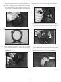
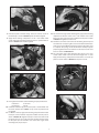
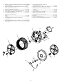
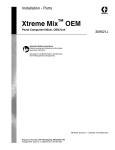
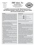
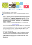
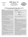
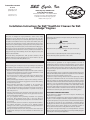
Instruction 510-0244
12-11-13
Copyright © 2013
by S&S® Cycle, Inc.
S&S Cycle, Inc
All rights reserved.
Printed in the U.S.A.
®
.
14025 Cty Hwy G PO Box 215
Viola, Wisconsin 54664
Phone: 608-627-1497 • Fax: 608-627-1488
Technical Service Phone: 608-627-TECH (8324)
Technical Service Email: [email protected]
Website: www.sscycle.com
Installation Instructions for S&S® Stealth Air Cleaners for S&S
X-Wedge® Engines
DISCLAIMER:
S&S parts are designed for high performance, closed course, racing
applications and are intended for the very experienced rider only. The
installation of S&S parts may void or adversely affect your factory warranty.
In addition such installation and use may violate certain federal, state, and
local laws, rules and ordinances as well as other laws when used on motor
vehicles used on public highways, especially in states where pollution laws
may apply. Always check federal, state, and local laws before modifying your
motorcycle. It is the sole and exclusive responsibility of the user to determine
the suitability of the product for his or her use, and the user shall assume all
legal, personal injury risk and liability and all other obligations, duties, and
risks associated therewith.
The words Harley®, Harley-Davidson®, H-D®, Sportster®, Evolution®, and all
H-D part numbers and model designations are used in reference only. S&S
Cycle is not associated with Harley-Davidson, Inc.
IMPORTANT NOTICE:
Statements in this instruction sheet preceded by the following words are of
special significance.
WARNING
Means there is the possibility of injury to yourself or others.
CAUTION
Means there is the possibility of damage to the part or motorcycle.
NOTE
Other information of particular importance has been placed in italic type.
S&S recommends you take special notice of these items.
WARRANTY:
SAFE INSTALLATION AND OPERATION RULES:
Before installing your new S&S part it is your responsibility to read and follow
the installation and maintenance procedures in these instructions and
follow the basic rules below for your personal safety.
•• Gasoline is extremely flammable and explosive under certain conditions
and toxic when breathed. Do not smoke. Perform installation in a well
ventilated area away from open flames or sparks.
•• If motorcycle has been running, wait until engine and exhaust pipes
have cooled down to avoid getting burned before performing any
installation steps.
•• Before performing any installation steps disconnect battery to eliminate
potential sparks and inadvertent engagement of starter while working
on electrical components.
•• Read instructions thoroughly and carefully so all procedures are
completely understood before performing any installation steps.
Contact S&S with any questions you may have if any steps are unclear or
any abnormalities occur during installation or operation of motorcycle
with a S&S part on it.
•• Consult an appropriate service manual for your motorcycle for correct
disassembly and reassembly procedures for any parts that need to be
removed to facilitate installation.
•• Use good judgment when performing installation and operating
motorcycle. Good judgment begins with a clear head. Don’t let
alcohol, drugs or fatigue impair your judgment. Start installation when
you are fresh.
•• Be sure all federal, state and local laws are obeyed with the installation.
•• For optimum performance and safety and to minimize potential
damage to carb or other components, use all mounting hardware that is
provided and follow all installation instructions.
•• Motorcycle exhaust fumes are toxic and poisonous and must not be
breathed. Run motorcycle in a well ventilated area where fumes can
dissipate.
All S&S parts are guaranteed to the original purchaser to be free of
manufacturing defects in materials and workmanship for a period of twelve
(12) months from the date of purchase. Merchandise that fails to conform to
these conditions will be repaired or replaced at S&S’s option if the parts are
returned to us by the purchaser within the 12 month warranty period or within
10 days thereafter.
In the event warranty service is required, the original purchaser must call or
write S&S immediately with the problem. Some problems can be rectified by a
telephone call and need no further course of action.
A part that is suspect of being defective must not be replaced by a Dealer
without prior authorization from S&S. If it is deemed necessary for S&S to
make an evaluation to determine whether the part was defective, a return
authorization number must be obtained from S&S. The parts must be packaged
properly so as to not cause further damage and be returned prepaid to S&S
with a copy of the original invoice of purchase and a detailed letter outlining
the nature of the problem, how the part was used and the circumstances at
the time of failure. If after an evaluation has been made by S&S and the part
was found to be defective, repair, replacement or refund will be granted.
ADDITIONAL WARRANTY PROVISIONS:
(1) S&S shall have no obligation in the event an S&S part is modified by any
other person or organization.
(2) S&S shall have no obligation if an S&S part becomes defective in whole or
in part as a result of improper installation, improper maintenance, improper
use, abnormal operation, or any other misuse or mistreatment of the S&S part.
(3) S&S shall not be liable for any consequential or incidental damages
resulting from the failure of an S&S part, the breach of any warranties, the
failure to deliver, delay in delivery, delivery in non-conforming condition, or
for any other breach of contract or duty between S&S and a customer.
(4) S&S parts are designed exclusively for use in Harley-Davidson® and other
American v-twin motorcycles. S&S shall have no warranty or liability obligation
if an S&S part is used in any other application.
1. Apply supplied thread locker to 1/16-27 pipe plug #50-8332, and
install it in unused hole in backing plate. See Picture 1.
2. For Muscle cover kits, remove the lanyards from the supplied
gasket by squeezing the rivets on the small end with a pair of
pliers as illustrated in Picture 2. This gasket will not be needed for
the installation on an S&S® X-Wedge® engine.
4. Thread the three ¼-20 x .825" socket button head screws #5000059 through the back plate as shown in Picture 4.
Picture 4
5. Install back plate mounting tabs #170-0202 loosely as shown in
Picture 5 with ¼-20 x .500" socket head screws #106-2084. These
screws have a thread lock patch, so thread locker is not needed.
Do not final tighten.
Picture 1
Picture 5
Picture 2
6. Trim off unneeded portion of back plate gasket #106-6022 as
shown in Picture 6. Only the three back plate mounting bold
holes are required. Place back plate gasket over screws in back
plate. Apply thread locker to the exposed threads. Picture 7.
3. Apply the supplied thread locker to the 10-24 x 1/4" panhead
screw and attach lanyards # 500-0095 to the back plate as shown.
Lanyards must be attached to the outer surface of the back plate.
See Picture 3.
Picture 6
Picture 3
2
Picture 10
Picture 7
12. For covers with single center mounting bolt, apply thread locking
compound to threads of two ¼-20 x .750" button head screws
#500-0060 and secure top plate and filter to back plate as shown
in Picture 11. Tighten to 90-100 in-lb.
13. For Muscle cover kits install cover over mounting studs and place
a washer #500-0094, spring #500-0093 and another washer #5000094 over each stud. While pushing the washers toward the cover
to compress the springs, insert the miniature hood-pins (lynch
pins) through the holes in the studs to secure the air cleaner cover
to the air cleaner. See Picture 12
14. For covers with single center mounting hole, place 5/16-18 x .500"
socket button head screw #50-0296-S through hole in cover.
Apply thread locking compound and thread into air cleaner top
plate in location shown in Picture 11. Torque to 10 ft-lb.
7. Hold back plate to throttle body, and start all three screws in
throttle body as shown in Picture 8, but do not final tighten.
8. Apply thread locking compound to 5/16-18 x .750 button head
screws and fasten back plate mounting tabs to cylinder heads as
shown in Picture 9. Do not final tighten.
Picture 8
510-0060
50-0286-S
Picture 11
Picture 9
9. Final tighten all fasteners to the following torque specifications:
1/4" fasteners
90-120 in-lb
5/16" fasteners
15 ft-lb
10. Hold filter and filter top plate to back plate as shown. Make sure
the arrow and the word “DOWN” on top cover are positioned at
the bottom.
11. For Muscle cover kit, apply thread locking compound to hex head
hood-pin screws and fasten top plate and filter to back plate as
shown in Picture 10. Tighten hood-pin screws to the low end of
the torque spec (90-100 in-lb) and rotate clockwise until the holes
for the lynch pin are horizontal. For covers with single center
mounting bolt, skip to step 12
Picture 12
3
1.Backplate, Air Cleaner, Stealth, Machined, Powder coated, WBlack,
Die Cast, X-Wedge®......................................................................170-0199
2.Filter, Air, Tapered, Standard Pleated, 5.500" x 6.000" x 2.375",
Cotton, Stealth Air Cleaner Kit................................................. 170-0043
3. Plate, Top, Air Filter, Molded, Plastic.......................................170-0026
4. Screw, SHCB, 5/16-18 x .500", Polished, Stainless Steel...... 500-0051
5. Screw, SHC, Flanged Button, 1/4-20 UNC x .750"................500-0060
6. Screw, SHCB, 1/4-20 UNC X .825"............................................... 500-0059
7.Screw,PH,10-24 x 1/4",Zinc,Steel
(each)...................................................................................................50-0041
10 pack............................................................................................... 50-0062
8.Screw,BHC,w/ Thread Lock,5/16-18 x 3/4",Chrome,
ASTM A574-92A...........................................................................50-0269-S
9.Bracket, Backplate Mounting, Stealth Air Cleaner, Chrome Plated,
Steel, X-Wedge®.............................................................................170-0202
10.Screw,SHC,w/ Thread Lock,1/4-20 x 1/2",
Zinc Plated,Alloy Steel................................................................ 106-2084
11. Plug,Pipe,3/4 Taper,1/16-27 NPTF x .156",Zinc,Steel..................50-8332
12.Gasket,Backplate Throttle Body, Stock CV/EFI
Standard........................................................................................... 106-1724
Lanyard Style.................................................................................. 170-0137
13.Screw, Hex, Hood-pin, 1⁄4-20, UNC...........................................500-0113
14.Washer, Fender, Chrome Plated..............................................500-0094
15.Spring, Wave Washer, Stainless Steel....................................500-0093
16.Lynch Pin.........................................................................................500-0083
17. Lanyard, 6" Stainless Steel.........................................................500-0095
18.Sealant, Loctite®, #243, 5ml, Blue (not shown)...................... 51-9003
1
12
11
10
2
6
9
3
7
8
4
5
14
13
16
15
17
4
3