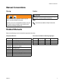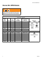
1
Installation - Parts
Xtreme
™
Mix
Plural Component Mixer, OEM Unit
Important Safety Instructions
Read all warnings and instructions in this manual.
Save these instructions.
See page 4 for model information, including maximum working pressure and approvals.
Graco Inc. P.O. Box 1441 Minneapolis, MN 55440-1441
Copyright 2005, Graco Inc. is registered to I.S. EN ISO 9001
OEM
309521J
Contents
Manual Conventions . . . . . . . . . . . . . . . . . . . . . . . . 3
Related Manuals . . . . . . . . . . . . . . . . . . . . . . . . . . . 3
Xtreme Mix OEM Models . . . . . . . . . . . . . . . . . . . . . 4
Warning . . . . . . . . . . . . . . . . . . . . . . . . . . . . . . . . . . . 5
Pressure Relief Procedure . . . . . . . . . . . . . . . . . . . 7
Assemble . . . . . . . . . . . . . . . . . . . . . . . . . . . . . . . . . 8
Pumps and Sensors . . . . . . . . . . . . . . . . . . . . . . 9
Control Box . . . . . . . . . . . . . . . . . . . . . . . . . . . . . 9
Grounding . . . . . . . . . . . . . . . . . . . . . . . . . . . . . 11
Air Controls . . . . . . . . . . . . . . . . . . . . . . . . . . . . 11
User Interface . . . . . . . . . . . . . . . . . . . . . . . . . . 12
Fluid Manifold . . . . . . . . . . . . . . . . . . . . . . . . . . 12
Proper Lifting . . . . . . . . . . . . . . . . . . . . . . . . . . . . . 15
Operation and Repair . . . . . . . . . . . . . . . . . . . . . . 15
Electrical Schematic . . . . . . . . . . . . . . . . . . . . . . . 16
2
Pneumatic Schematic . . . . . . . . . . . . . . . . . . . . . . 18
Parts . . . . . . . . . . . . . . . . . . . . . . . . . . . . . . . . . . . . 20
Xtreme Mix Proportioner . . . . . . . . . . . . . . . . . . 20
Pneumatic Control 245803 . . . . . . . . . . . . . . . . 22
User Interface 245804 . . . . . . . . . . . . . . . . . . . . 24
Pump Air Manifold 245802 . . . . . . . . . . . . . . . . 25
Metering Valve Manifold 245824 . . . . . . . . . . . . 26
Sampling Valve 245143 . . . . . . . . . . . . . . . . . . . 26
Metering Valve 245846 . . . . . . . . . . . . . . . . . . . 27
Fluid Manifold 245833 . . . . . . . . . . . . . . . . . . . . 28
Sensor 245825 . . . . . . . . . . . . . . . . . . . . . . . . . 29
Technical Data . . . . . . . . . . . . . . . . . . . . . . . . . . . . 30
Graco Standard Warranty . . . . . . . . . . . . . . . . . . . 32
Graco Information . . . . . . . . . . . . . . . . . . . . . . . . . 32
309521J
Manual Conventions
Manual Conventions
Warning
Caution
WARNING
A warning alerts you to possible serious injury or
death if you do not follow instructions.
Symbols, such as fire and explosion (shown), alert you
to a specific hazard and direct you to read the indicated hazard warnings (pages 5-6).
CAUTION
A caution alerts you to possible equipment damage or
destruction if you do not follow instructions.
Note
A note indicates additional helpful information.
Related Manuals
Refer to the following manuals for detailed component information.
Component Manuals
Manual
309535
309518
311762
309347
or 309348
312145
309524
309525
308981
309615
309568
309521J
This manual available in following languages:
Description
Manual
Language
Manual
Language
Xtreme Mix Operation
Xtreme Mix Repair
Xtreme Displacement Pump
King Air Motor
King Quiet Air Motor
XTR Spray Gun
VISCON HP Heater
Heated Hose Kit
Husky 716 Diaphragm Pump
Heater Bracket Kit
Remote Manifold Kit
309521
309538
309539
English
French
Spanish
309540
309546
309604
German
Swedish
Japanese
3
Xtreme Mix OEM Models
Xtreme Mix OEM Models
WARNING
Do not install equipment approved only for non-hazardous location in a hazardous area. Substitution of
components may impair intrinsic safety. See page 5.
Approved for Hazardous Location
Class I, Div 1, Group D
Xtreme
Mix
Part No.
233871
233872
233873
233874
233875
233876
233877
233878
234024
Series
Pump
Part No.
Pump
Description
Maximum Working
Pressure
psi (MPa, bar)
A
A
A
A
A
A
A
A
A
249274
249275
249276
249277
249278
249279
249280
249281
none
45:1 King
56:1 King
68:1 King
80:1 King
45:1 Quiet King
56:1 Quiet King
68:1 Quiet King
80:1 Quiet King
4500 (31, 310)
5600 (38.6, 386)
6800 (46.9, 469)
7250 (50, 500)
4500 (31, 310)
5600 (38.6, 386)
6800 (46.9, 469)
7250 (50, 500)
Approvals
ll 2 G
Conforms to
FM std 3600 & 3610 for
use in Class I Div 1
Group D
T3 Hazardous locations
CAN/CSA
22.2 No. 157-92
& No. 1010.1-92
Approved for Non-hazardous Location
233879
233880
233881
233882
233883
233884
233885
233886
234025
4
A
A
A
A
A
A
A
A
A
249274
249275
249276
249277
249278
249279
249280
249281
none
45:1 King
56:1 King
68:1 King
80:1 King
45:1 Quiet King
56:1 Quiet King
68:1 Quiet King
80:1 Quiet King
4500 (31, 310)
5600 (38.6, 386)
6800 (46.9, 469)
7250 (50, 500)
4500 (31, 310)
5600 (38.6, 386)
6800 (46.9, 469)
7250 (50, 500)
Conforms to UL std 61010A-1
CSA std C22.2 No 1010.1-92
309521J
Xtreme Mix OEM Models
Warning
Skin Injection Hazard
High-pressure fluid from gun, hose leaks, or ruptured components will pierce skin. This may look like just
a cut, but it is a serious injury that can result in amputation. Get immediate surgical treatment.
•
Do not point the gun at anyone or at any part of the body.
•
Do not put your hand or fingers over the gun fluid nozzle.
•
Do not stop or deflect leaks with your hand, body, glove, or rag.
•
Do not “blow back” fluid; this is not an air spray system.
•
Follow Pressure Relief Procedure, page 7, when you stop spraying and before cleaning, checking,
or servicing equipment.
•
Use lowest possible pressure when flushing, priming, or troubleshooting.
•
Never spray without tip guard and trigger guard installed.
•
Engage trigger lock when not spraying.
•
Tighten all fluid connections before operating the equipment.
•
Check hoses, tubes, and couplings daily. Replace worn or damaged parts immediately. High pressure hose cannot be recoupled; replace the entire hose.
Fire and Explosion Hazard
Solvent and paint fumes in work area can ignite or explode. To help prevent fire and explosion:
•
Use equipment only in well ventilated area.
•
Eliminate all ignition sources, such as pilot lights, cigarettes and plastic drop cloths (potential static
arc).
•
Do not plug or unplug power cords or turn lights on or off when flammable fumes are present.
•
Keep the work area free of debris, including solvent, rags, and gasoline.
•
Ground equipment and conductive objects. See Grounding, page 11.
•
Hold gun firmly to side of grounded pail when triggering into pail.
•
Use only grounded hoses.
•
If there is static sparking or you feel an electric shock, stop operation immediately. Do not use
equipment until you identify and correct the problem.
•
If connecting PC for data download, PC must be in non-hazardous location and a safety barrier must
be installed. See Xtreme Mix software documentation.
•
Keep a fire extinguisher in the work area.
Electric Shock Hazard
Improper grounding, wiring, or usage of the system can cause electric shock.
309521J
•
All electrical wiring must be done by a qualified electrician and comply with all local codes and regulations.
•
Connect only to grounded power source.
•
Turn off and disconnect power at the main switch before disconnecting any cables and before servicing equipment.
5
Xtreme Mix OEM Models
Warning
Moving parts hazard
Moving parts can pinch or amputate fingers and other body parts. Pressurized equipment can start accidentally and cause serious injury.
•
Keep clear of moving parts.
•
Do not operate equipment with protective guards or covers removed.
•
Before checking or servicing equipment, follow Pressure Relief Procedure, page 7. Disconnect
power or air supply.
•
Do not move or lift pressurized equipment.
Equipment Misuse Hazard
Misuse can cause serious injury or death.
•
For professional use only.
•
Use equipment only for its intended purpose. Call your Graco distributor for information.
•
Read manuals, warnings, tags, and labels before operating equipment. Follow instructions.
•
Check equipment daily. Repair or replace worn or damaged parts immediately.
•
Do not alter or modify equipment. Use only Graco parts and accessories.
•
Do not exceed the maximum working pressure or temperature rating of the lowest rated system component. See Technical Data in all equipment manuals.
•
Use fluids and solvents that are compatible with equipment wetted parts. See Technical Data in all
equipment manuals. Read fluid and solvent manufacturer’s warnings.
•
Route hoses and cables away from traffic areas, sharp edges, moving parts, and hot surfaces.
•
Do not kink or overbend hoses or use hoses to pull equipment.
•
To lift equipment, follow instruction, page 15.
•
Comply with all applicable approval requirements and safety regulations.
Burn Hazard
This equipment is used with heated fluid, which can cause equipment surfaces to become very hot. To
avoid severe burns:
•
Do not touch hot fluid or equipment.
•
Allow equipment to cool completely before touching it.
•
Wear gloves if fluid temperature exceeds 110° F (43° C).
Toxic Fluid or fumes Hazard
Toxic fluids or fumes can cause serious injury or death if splashed in the eyes or on skin, inhaled, or swallowed.
•
Read Material Safety Data Sheet (MSDS) to know the specific hazards of the fluids you are using.
•
Store hazardous fluid in approved containers, and dispose of it according to applicable guidelines.
Personal Protective Equipment
You must wear proper protective equipment when operating, servicing, or when in the operating area of
the equipment to help protect you from serious injury, including eye injury; inhalation of toxic fumes; and
hearing loss. This equipment includes but is not limited to:
•
Protective eyewear
•
Gloves, clothing, and respirator as recommended by the fluid and solvent manufacturer
•
Hearing protection
Recoil Hazard
The gun can recoil when triggered at a very high pressure. If unprepared, this could force your hand back
or cause you to fall and injure yourself. Be sure you have firm footing and hold the gun securely.
6
309521J
Pressure Relief Procedure
Pressure Relief Procedure
6. Hold a metal part of the gun firmly to a grounded
metal pail. Trigger gun to relieve pressure.
WARNING
Follow Pressure Relief Procedure when you stop
spraying and before cleaning, checking, servicing, or
transporting equipment. Read warnings, page 5.
1. Engage trigger lock.
7. Engage trigger lock.
2. Press Stop
8. Place waste container under sampling valves, then
open valves A and B slowly to relieve pressure
between pump and metering valves.
.
SUPPLY AIR
PRESSURE
I
O
PL U RAL COM PON EN T PROPORTI ON ER
3. Close main air shutoff valve on air supply line and on
unit. Turn off air regulator.
Open
Open
Close
Close
4. Close fluid sampling and shutoff valves A and B.
A
B
PSI
Bar
MPa
Close
Close
Close
Close
A
PSI
Bar
MPa
I
9. Close sampling valves A and B.
B
O
Close
5. Disengage trigger lock.
309521J
Close
A
B
7
Assemble
Assemble
5
2
913
910
911
10
901
904
3
905
307
912
903
7
914
915
721
6
4
902
FIG. 1
8
309521J
Assemble
Pumps and Sensors
•
If using feed pumps, do not allow feed pressure
to exceed 25% of spray pressure.
•
For accurate ratios, pump lowers must be
same size.
•
If installing 234024 or 234025, the pump size
has not been set in the software. To set pump
A and B size and A and B sensor calibration
factors, you need Xtreme Mix Data Download
software, part no. 246322 for proportioners
located in a non-hazardous area, or part no.
246397 for proportioners located in a hazardous area.
Calibration values are on pump A and B sensors.
Control Box
1. Mount control box (3) to mounting plate (10). FIG. 1.
a. Slide gasket (307) over back of pneumatic control box (3), against lip. Insert box through
mounting plate (10).
b.
Secure box (3) to plate (10) with 8-32 UNC
screws (912).
Mount box (3) vertically for optimum alternator and
component life.
2. Secure mounting plate (10) to cart/stand. Install fasteners (provided by installer) through six 0.3” (7.62
mm) mounting plate holes.
3. Connect conduit (721) from two sensors (7) to pneumatic control box (3).
Pump Size Values
Pump
Size Value
(cc/cycle)
45:1
250
56:1
220
68:1
180
80:1
145
1. Secure magnet holders (903) to the pump (2) motor
displacement rods with screws (905). FIG. 1.
2. Install a short magnet strip then a long one (904) on
each magnet holder (903). Secure with tape supplied.
3. Secure pumps (2) on mounting brackets with two
3/8 x 1-1/4” screws (913), lockwashers (914), and
nuts (915).
Conduit must be used. Approximately 62” (1575
mm) of cable and conduit provided; do not
lengthen.
4. Wire two sensors (7) to control box 18-pin connector. Connect sensor A, then sensor B wires in pairs
sequentially – black/green, black/red, black/white –
to pins 2-13. See Electrical Schematic, page 16.
5. Connect 18-pin connector to main control board
connector (F). FIG. 2.
10 9 8 7 6 5 4 3
F
3
J2
4. Secure sensors (7) on pumps and pump mounting
brackets with two screws (913), lockwashers (914),
and nuts (915).
3
4
5
J1
6
7
8
9 10
-
+
FIG. 2 Control Box
309521J
9
Assemble
3
A
3
B
2
3
2
501
C
F
D
H
J
G
1
E
902
5
6
901
K
L
Key:
A
B
C
D
E
F
G
H
J
K
L
2
Pump A Air
Pump B Air
Pump A Pilot Air
Pump B Pilot Air
Air Supply
Metering Valve A - CLOSE
Metering Valve A - OPEN
Metering Valve B- CLOSE
Metering Valve B- OPEN
Sensor A Cable
Sensor B Cable
Pump
3
6
501
901
902
Pneumatic Control
Metering Valve Manifold
Pneumatic Valve
Air Filter
Ground Wire Assembly
1
Ground manifold to true earth ground.
2
Ground by connecting ground wire from control box (3) to
manifold (6).
3
Ground by connecting ground wire from pumps (2) to
manifold (6).
FIG. 3
10
309521J
Assemble
Grounding
Standard Setup
FIG. 1 and FIG. 3
WARNING
Read warnings, page 5, and follow instructions below.
1. Connect 12 gauge ground wire (provided by
installer) from pneumatic control box (3) ground
screw (312, page 22) to metering valve manifold (6).
Refer to FIG. 3.
1. Mount pneumatic control assembly (3) to mounting
plate (10). FIG. 1.
2. Connect an air line (A and B) between each pneumatic valve (501) and pump air motor inlet. FIG. 3.
36” (914 mm) hoses provided. Installer may provide different lengths.
2. Connect ground wire from each pump (2) to metering valve manifold (6).
3. Connect air supply from air manifold’s 5 micron air
filter (518) to control box air inlet (not shown).
3. Connect ground wire assembly (902) to fluid manifold (6). Connect clamp end to a true earth ground
before starting unit.
The alternator requires 12-15 scfm of air to function correctly.
•
Do not use 3/8” (9.5 mm) ID air supply tubing
longer than 24” (610 mm) from air filter to
control box air inlet.
•
Do not restrict control box exhaust air.
Air Controls
Do not use air supply hose smaller than 3/4” (19
mm) ID. Smaller hose could restrict air flow and
cause alternator, solenoids, or Mac valves to malfunction. Check air supply gauge at pump
changeover; air pressure should not drop.
Increased back pressure can cause a drop in
alternator power output, resulting in delayed valve
action and processor shutdown and reboot.
4. Connect tubing (C and D) from solenoids to each
pneumatic valve (501).
5. Mount air supply filter (901) to cart/stand and connect air supply (E) to air manifold (5) air inlet.
309521J
11
Assemble
User Interface
10 9 8 7 6 5 4 3
FIG. 4 and FIG. 5
301
1. Connect display board (410) communication cable
(416) to J1 on main circuit board (301).
3
J2
J1
2. Connect data cable (406 - 7-pin connector) to J2.
315
3
4
5
6
7
8
9 10
WARNING
The user interface must be grounded. Read warnings,
page 5.
3. Connect ground wire (315) to ground stud on back
of cover with nut (311).
4. Secure cover (4) to mounting plate (10) with lockwashers (911) and nuts (910). FIG. 1.
-
+
FIG. 5 Control Box
Fluid Manifold
CAUTION
Do not assemble static mixer directly to fluid manifold.
Install static mixer after first 50 ft. (15 m) of hose to
ensure material is completely mixed. Spraying
unmixed material could necessitate rework of part
sprayed. See Setup in Xtreme Mix Operation manual.
410
4
Install Sampling Valves 244683
311
416
Install sampling valves (918) into the metering valves
(601). Install barb fitting (919) and tubing (920) into each
sampling valve. FIG. 7.
406
FIG. 4: Cover - back view
12
309521J
Assemble
Cart-mounted
601
1. Secure metering valve assembly (6) to cart/stand
with screws (913), washer (914), and nuts (915).
FIG. 1, page 8.
918
2. Connect fluid lines (provided by installer) between
pumps and metering valves.
3. Cut air line tubing (included) to length needed to
connect between metering valves (601) and solenoid outlets. FIG. 3, page 10, and FIG. 6.
607
919, 920
A side 606
Bottom of Valve A
B side 611
Bottom of Valve B
FIG. 7
DOSING VALVES
AIR MOTOR
PILOT VALVES
OPEN
Pilot Valve A side
607
Pilot Valve B side
E
606
CLOSE
913
Top of Valve B
Top of Valve A
FIG. 6: Control Box - bottom
611
Remote Fluid Manifold
To install remote fluid manifold, order part no.
15A898. All other parts referred to in the following
procedure are parts you remove from the standard manifold and reuse or parts the installer
must supply.
1. Remove metering valves (601) and shutoff valves
(606, 611) from fluid manifold (607). FIG. 7.
2. Install metering valves (601) and shutoff valves
(606, 611) onto fluid metering manifold 15A898. FIG.
8.
•
Maximum length of tubing is 36” (914 mm).
Locate fluid manifold as close as possible.
15A898
914
915
FIG. 8
CAUTION
Do not assemble static mixer directly to fluid manifold.
Install static mixer after first 50 ft. (15 m) of hose to
ensure material is completely mixed. Spraying
unmixed material could necessitate rework of part
sprayed. See Setup in Xtreme Mix Operation manual.
3. Secure fluid metering manifold 15A898 on the
cart/stand with 2 screws (913), washers (914) and
nuts (915).
309521J
13
Assemble
4. Screw ball valves (606, 611 - purchased separately)
into fluid mix manifold (607).
5. Select appropriate fittings and fluid hose sizes and
lengths to connect between fluid metering manifold
15A898 and mix manifold (607).
Balance pressure drops in the 2 lines as
instructed below to assure an accurate mix ratio.
6. Connect fluid lines (provided by installer) between
pumps and metering valves (601).
7. Connect mixed material hose to fluid mix manifold
(607) outlet (E).
8. Cut air line tubing (included) to length needed to
connect between metering valves (601) and solenoid outlets. FIG. 3, page 10, and FIG. 6, page 13.
To calculate pressure loss:
Pressure Loss = 0.000273 x Q x V L
D4
Q =
V =
L =
D4 =
Flow (GPM)
Viscosity in centipoise
Length of pipe in feet
Pipe diameter to the 4th power
Example: If you need to pump 1 gpm of high solids paint
(40 seconds in a Zahn #2 cup = 100 cp) 100 ft. in a system using 1/4” pipe:
Pressure Loss = 0.000273 x 1 gpm x 100 cp x 100 ft.
(.364 ID) .018 D4 factor
Pressure Loss = 152 psi
Reduce pressure loss by using:
9. Cut air line tubing, included, (F, G, H, J - FIG. 3,
page 10) to length needed to connect between
metering valves (601) and solenoid outlets.
10. Connect ground wires.
Balancing Back Pressure
This procedure is for the remote fluid manifold
only.
Flow rates and/or viscosity differences between component materials can create different pressure drops from
the proportioner to the manifold, causing unequal back
pressure. This will effect mix ratio accuracy.
•
•
•
•
Large diameter pipe or tubing
Constant tubing or pipe size
Long runs without bends
Long radius elbows
You can balance differences in component back pressure by adjusting hose diameter and length.
D4 = .018 for 1/4” pipe
.06 for 3/8” pipe
.15 for 1/2” pipe
Using the previous example (.000273 x 1 x 100 x 100 =
2.73):
Pressure drop:
14
1/4” pipe = 152 psi
3/8” pipe = 46 psi
1/2” pipe = 18 psi
309521J
Proper Lifting
Proper Lifting
WARNING
Follow instructions below to avoid dropping or swinging unit or being struck by the cart handle, which can
cause serious injury or damage to equipment.
Either remove the cart handle or secure it to the cart
before lifting the unit. Connect a bridle swing, hooking
an end to each of the Xtreme Mix air motor rings. Hook
the center ring on a hoist. See FIG. 9. Carefully lift the
Xtreme Mix unit; make sure it balances evenly.
FIG. 9
Operation and Repair
For operating instructions, including data collection, see
Xtreme Mix Operation manual.
309521J
For troubleshooting, alarm information, and repair
instructions, see Xtreme Mix Repair manual.
15
Electrical Schematic
Electrical Schematic
1
J6
1
2
3
1
2
3
Main Circuit
Board
245705
15VDC
COM
R
BL
Jumper (15V)
1
J5
1
2
3
4
5
6
7
8
9
10
11
12
1
2
3
4
5
6
7
8
9
10
11
12
18
17
16
15
14
13
12
11
10
9
8
7
6
5
4
3
2
1
1
1
1
2
3
4
5
6
7
1
1
2
3
4
5
6
J4
Solenoids
+
-
R
BL
R
BL
R
BL
R
BL
R
BL
18
17
16
15
14
13
12
11
10
9
8
7
6
5
4
3
2
1
+
-
Metering
Valves
Metering Valve B
+
-
+
-
Metering Valve A
Pump A
Air Motors
Pump B
S
W
BL-W
R
BL-R
G
BL-G
3
6
1
4
2
5
W
BL-W
R
BL-R
G
BL-G
3
6
1
4
2
5
Sensor
243678
Sensor
243678
S
J2
J1
Case Gnd Clip
1
2
3
4
5
6
7
R
W
BL
J1
1
2
3
4
5
6
1
2
3
4
5
6
1
2
3
4
5
6
Key:
BL Black
BR Brown
BL-GBlack with green
BL-RBlack with red
16
BL-WBlack with white
G Green
GNDGround
R Red
S
W
Shield
White
309521J
Electrical Schematic
301
304
Power
Supply
Barrier
Board
Power
Supply
Air Input
Front Panel
Comport Pin
Front View
Alarm +
Alarm COM
COM Port
RS232
Connector
Alarm 15A849
1
2
3
R
W
BL
1
2
TX
RX
GND
3
Start
3
4
B
A
Start/Stop
Switch
15A851
GND
Light
Display Board
245706
1
2
3
4
5
6
Stop
J2
1
2
3
4
5
1
2
3
4
5
R
W
BR
G
BL
1
2
3
BL
R
G
1
Key Switch
15A852
J3
1
2
3
GND
2
1
7
8
+
309521J
2
1
2
1
2
Key Switch
momentary
-
17
18
3/4” Air Filter
Auto Drain
20 micron
Gauge
507
Air Regulator
Gauge
King Motor A
3/4” Ball Valve
bleed type
3/8” Air Reg.
Auto Drain
5 micron
100 psi (0.7
MPa, 7 bar)
518
306e
To Manifold
3/8” tube
Alternator Air
Regulator
110 psi
(0.8 MPa,
8 bar) Relief
Valve
524
Pump B Pilot
Pump A Pilot
90/110 psi 0.6/0.8
MPa, 6.2/8 bar)
Relief Valve
79
501
King Motor B
Air Supply
1/2” x 24” long
26 psi (79 kPa, 1.8 bar)
Relief Valve
306t
Position 4
12 VDC
Solenoid
Position 3
12 VDC
Solenoid
Position 2
Solenoid
12 VDC
Position 1
12 VDC
Solenoid
Air
Exhaust
Turbine / Power Supply
304
3-way valve
To Pump B Pilot
3-way valve
To Pump A Pilot
e
os
Cl 2”
B 5 /3
en
Op
B
e
os
Cl
A
2”
5 /3
en
Op
A
Manifold
Valve
B Metering
Valve
A Metering
Pneumatic Schematic
Pneumatic Schematic
FIG. 10
309521J
Pneumatic Schematic
309521J
19
Parts
Parts
Xtreme Mix Proportioner
5
2
913
908/909
908
910
911
10
901
904
3
905
307
912
903
7
914
915
721
6
902
20
4
918, 919, 920
309521J
Parts
Xtreme Mix Proportioner
Part Numbers
Approved for Hazardous Location
(Class 1, Div 1, Group D)
Approved for Non-hazardous Location
Xtreme Mix
Pump (2)
Plate (10)
233871
233872
233873
233874
233875
233876
233877
233878
234024
249274 (45:1)
249275 (56:1)
249276 (68:1)
249277 (80:1)
249278 (45:1)
249279 (56:1)
249280 (68:1)
249281 (80:1)
none
246332
246334
246336
246338
246332
246334
246336
246338
246338
Xtreme Mix
Pump (2)
Plate (10)
233879
233880
233881
233882
233883
233884
233885
233886
234025
249274 (45:1)
249275 (56:1)
249276 (68:1)
249277 (80:1)
249278 (45:1)
249279 (56:1)
249280 (68:1)
249281 (80:1)
none
246333
246335
246337
246339
246333
246335
246337
246339
246339
Refer to page 4 for additional model information.
Includes:
Kit 246149, Item 9
Ref.
No.
Part No. Description
2
3
4
5
6
245803
245804
245802
245824
7
9
10
918
919
245825
246149
920
116750
245143
116746
PUMP; see table above; see pump
manual for parts
PNEUMATIC CONTROL; page 22
USER INTERFACE; page 24
PUMP AIR MANIFOLD
METERING VALVE MANIFOLD;
page 26
SENSOR; page 29
KIT; includes 901-917
PLATE; see table above
SAMPLING VALVE; parts page 26
FITTING; 1/8 npt x 1/4” (6.4 mm)
tube; see page 26
TUBE, nylon; 5 in. (12.7 cm); see
page 26
Qty.
2
1
1
1
1
2
1
1
2
2
2
Ref.
No.
901
902
903
904
905
906
907
Part No.
117628
244524
15A847
15A814
104092
511352
054753
908
113498
909
116643
910
911
912
913
914
915
916
100015
100016
103196
100004
100133
100131
054139
917
C12508
Description
Qty.
AIR FILTER; 3/4 npt
1
GROUND WIRE, with clamp
1
MAGNET HOLDER
2
MAGNET STRIP
2
SCREW; 10-24 UNC
4
STATIC MIXER, not shown
1
TUBING, nylon, black; 0.156”
(4 mm), 10 ft. (3 m), not shown
SAFETY RELIEF VALVE; 110 psi
1
(0.8 MPa, 8 bar)
SAFETY RELIEF VALVE; 90 psi
1
(621 kPa, 6.2 bar)
NUT; 1/4-20 UNC
4
LOCKWASHER
4
SCREW; 8/32 UNC
6
SCREW; 3/8 UNC
8
LOCKWASHER
8
NUT; 3/8-16 UNC
8
TUBING, nylon; 0.5” (13 mm); 3 ft.
★
(0.9 m), not shown
TUBING, nylon; 0.375” (9.5 mm); 3
★
ft. (0.9 m), not shown
★ Order length needed from distributor.
309521J
21
Parts
Pneumatic Control 245803
Item 3, page 21
a
d
b
p
k a
n
f h
g
e
e
f
303
m
302
f
t
c
304
315
320
306
c
311
s
j
b
321
301
313
312
TO SOLENOIDS
306r
317
FROM TURBINE
POWER Ref. 304
307
TO PUMP POSITON
SENSOR 314
304
MOTOR A
305
309
MOTOR B
310
306
B PUMP
REF
A PUMP
310
22
316
313
309521J
Parts
Pneumatic Control 245803
Ref.
No.
Part No. Description
301 245705 CIRCUIT BOARD
301a 15C318 FUSE, circuit board
302‡
SCREW; 8-32 UNC
303‡
COVER
304** 245854 ALTERNATOR MODULE; includes
items 304a-304e
304a 193154 • GASKET
304b 15A853 • WIRE HARNESS
304c 111225 • TUBE FITTING; 90°
304d 114380 • SCREW; M5 x 25
304e 249254 • TURBINE ALTERNATOR
305‡
LOCKNUT; 8-32 UNC
306‡
SOLENOID MODULE, IS; includes
items 306a-306t
306a 15A822 • MANIFOLD
306b 117356 • VALVE, 12 VDC, IS
306c 114263 • FITTING; 1/8 npt x 5/32” (4 mm)
tube
306d‡
• NIPPLE; 1/4 npt
306e 115243 • AIR REGULATOR; 1/4 npt
306f 115841 • ELBOW, swivel; 1/4 npt x 3/8”
(9.5 mm) tube
306g 160701 • ELBOW, street; 1/8 npt(m x f)
306h 108190 • GAUGE,
306j‡
• GASKET, neoprene
306k‡
• GASKET, neoprene
309521J
Qty.
1
1
4
1
1
1
1
2
4
1
2
1
1
4
6
1
1
3
1
1
1
1
Ref.
No.
Part No. Description
306n‡
• PLUG, pipe; 1/8-27 ptf
306p 114128 • ELBOW; 1/4 npt x 1/2” (13 mm)
tube
306q† 112512 • WIRE FERRULE, orange, not
shown
306r 117369 • CONNECTOR, 12 position
306s 150278 • ADAPTER, 1/4 x 1/8 npt
306t 117480 • SAFETY RELIEF VALVE, 26 psi
(179 kPa, 1.8 bar)
307 15A800 GASKET, neoprene
309‡
SCREW; M5 x 10
310 590385 TUBE, poly-flo; 3/8” OD; 1 ft. (3 m)
311‡
NUT, KEPS; #10-24
312 104029 GROUNDING STUD
313 15A849 WIRE HARNESS, alarm
314 117442 CONNECTOR, 18 position
315 15B090 GROUNDING WIRE, door
316 15B056 LABEL, air connections
317 111307 LOCKWASHER
320 118132 LOCKWASHER, terminal
321 118129 SPACER, 8-32 UNC x 5” (127 mm)
Qty.
5
1
8
1
1
1
1
2
★
1
1
1
1
1
1
1
1
1
IS = intrinsically safe
**
Alternator bearing repair kit 223688 available.
‡
Not available for order from Graco.
★ Order length needed from distributor.
23
Parts
User Interface 245804
Item 4, page 21
414,
415
Ref.
407
Ref.
403
Ref.
416
Ref. 407
404
15A804
Ref.
406
416
410
411
401
407
Back View
406
418
413
412
Ref. 405
405,419
409
15A806
Ref. 403
403
Ref.
No.
401‡
403
404
405
406
407
409*
410
411‡
412
413‡
24
Part No. Description
15A851
15A801
15C335
15A850
15A852
245706
15A856
COVER
WIRE HARNESS, start/stop
GASKET
KNOB
WIRE HARNESS, data port
WIRE HARNESS, key switch
LABEL, alarm code
CIRCUIT BOARD
SCREW; 4-40
DISPLAY PANEL
NUT; 4-40
Qty.
1
1
1
1
1
1
1
1
2
1
4
Ref.
No.
Part No. Description
Qty.
414‡
MOUNT
415‡
STRAP
416 15A854 WIRE HARNESS, display
418‡
WASHER
419 107232 SET SCREW
3
3
1
4
1
‡ Not available for order from Graco.
*
Alarm Code Labels
Item 409, English provided. To order other languages:
Part No.
Languages
15B843
15B844
Chinese, Finnish, Portuguese, Greek, Swedish, Italian
English, Spanish, French, German, Korean, Japanese
309521J
Parts
Pump Air Manifold 245802
Item 5, page 21
520
516
501
515
523
502
522
504
505
504
506
503 513
507
527
524
508
513
519
528
521
518
1
517
510
511
514
503
525
512
526
TI2295B
1
309521J
Ref.
No.
Part No. Description
501
502
503
504
505
506
507
508
510
511
512
513
514
515
516
517
518
519
520
C59752
108307
101689
112166
15A820
15A821
117332
100840
15A819
160032
117346
117364
108849
15B554
100549
165198
119644
114316
114151
521
522
523
524
100721
512912
100896
113498
525
526
527
528
117443
240900
158962
113911
VALVE, 3-way
ELBOW; 3/4 npt
PRESSURE GAUGE
SCREW; 1/4-20 UNC
MANIFOLD
PLATE, direction
REGULATOR
ELBOW; 1/4 npt
MANIFOLD BLOCK
NIPPLE; 3/4 npt
SHUTOFF VALVE, vented
O-RING, nitrile
SCREW; 1/4-20 UNC
HOSE; 3/4 npt; 4 ft. (1.2 m)
ELBOW, 90°; 3/4 npt
NIPPLE; 1/4 x 3/8 npt
FILTER; 3/8 npt; 5 micron
ELBOW, swivel; 3/8 npt
ELBOW, swivel; 1/8 npt x 5/32” (4
mm) tube
PLUG; 1/4-18 nptf
MUFFLER; 1/2 npt
BUSHING; 3/4 x 1/2 npt
SAFETY RELIEF VALVE; 110 psi
(0.8 MPa, 8 bar)
STANDOFF, aluminum, 8-32 UNC
HOSE; 3/4 npt; 2.5 ft. (0.76 m)
ELBOW, 1/8 (m) x 1/4 (f)
GUAGE, 1/8, air
Qty.
2
2
2
4
1
1
1
1
1
1
1
3
2
2
2
1
1
1
2
3
2
2
1
2
1
1
1
100 psi (0.7 MPa, 7 bar) setting.
25
Parts
Metering Valve Manifold 245824
Item 6, page 21
Ref.
No.
601
606
607
611
601
918
Part No. Description
245846 METERING VALVE; page 27
245861 SHUTOFF VALVE; see manual
306861
245833 FLUID MANIFOLD; page 28
245860 SHUTOFF VALVE; see manual
306861
918c
918h
918g
918d
918f
918b
918e
918a
Qty.
2
1
1
1
606 (A side)
611 (B side)
607
*919
Sampling Valve 245143
*920
Item 918
Ref.
No.
Part No. Description
918a
918b
918c
918d
918e
918f
918h
245110
197681
197332
107536
110082
111457
187060
26
KNOB
HOUSING
SEAT
BALL, carbide
RETAINING RING
O-RING, PTFE
GASKET
Qty.
*
See page 21 for part no. and description.
1
1
1
1
1
2
1
309521J
Parts
Metering Valve 245846
627
621
622
*† 637
*† 634
639*†
*† 638
*† 632
626
628
631
▲ 629
623
636
630†
*† 633
645*†
† 635
644†
645*†
624
646
*† 643
647
625
Ref.
No.
621
622‡
623‡
624‡
625
626
627
628
629▲
630†
631
632*†
633*†
634*†
Part No. Description
598140 ELBOW, 1/8 npt(m) x 5/32” (4 mm)
tube
VALVE CAP
PISTON
CYLINDER
15B545 PISTON ROD
15A834 TIE ROD
15A835 PACKING NUT
15A833 INLET HOUSING
180233 WARNING LABEL
245850 FLUID NEEDLE
111040 LOCKNUT, nylon; 5/16 UNC-3B
O-RING, nitrile
O-RING, nitrile
O-RING, nitrile
309521J
621
Qty.
2
1
1
1
1
2
1
1
1
1
1
1
1
1
Ref.
No.
Part No. Description
635†
636
637*†
638*†
639*†
643*†
644†
645*†
646
647
109141 SPRING
102040 LOCKNUT; 1/4 UNC
V-PACKING, UHMWPE
189901 GLAND, male
V-PACKING, leather
O-RING, buna-n
15A830 SEAT
107079 O-RING, PTFE
15A832 SEAT HOUSING
102637 SCREW; 3/8 UNC-2A
*
†
‡
▲
Qty.
1
2
6
1
5
1
1
2
1
4
Parts included in kit 234098.
Parts included in kit 234131.
Not available for order from Graco.
Replacement Warning labels available at no cost.
27
Parts
Fluid Manifold 245833
Item 607, page 26
676
675
669
674
665
668
661
670
*662
*663
*665
*664
*665
*666
*667
671
Ref.
No.
Part No. Description
661
662*
663*
664*
665*
666*
667*
668
15A823 PLUG
107098 O-RING, PTFE
107313 O-RING, PTFE
SEAT
103341 O-RING, PTFE
BALL, metallic
117333 SPRING
PLUG; 3/8 npt
28
Qty.
2
2
2
2
5
2
2
4
Ref.
No.
Part No. Description
669
670
671‡
674
675
676
15A825 PIPE, outlet
192977 PIPE, center
HOUSING
111307 LOCKWASHER
116343 GROUND SCREW,; M5 x 0.8
159239 NIPPLE; 3/8 x 1/2 npt
*
Parts included in kit 234100.
‡
Not available for order from Graco.
Qty.
1
1
1
2
2
1
309521J
Parts
Sensor 245825
Item 7, page 21
716†
712†
704†
703†
715
720†
†714
710*
†701
1
709*
702*
†707
705*
719*
713*
†706
721*
711*
†708
Ref.
No.
Part No. Description
701†
702*
703†
704†
705*
706†
707†
708†
709*
710*
711*
196280
15A818
243500
115925
117331
115917
110004
196289
116024
101855
112546
CAP
COVER
BOARD
SPACER
CABLE
SENSOR
O-RING, PTFE
CAP
TAB TERMINAL
SCREW; 4-24 UNC
SCREW; 4-40 taptite
Qty.
1
1
1
2
1
1
1
1
1
1
2
Ref.
No.
Part No. Description
712†
713*
714†
715
716†
719*
720†
721*
15A817
117569
154741
245831
104765
117586
C20272
117582
*
1
2
1
1
1
2
1
★
Parts included in kit 246345.
† Parts included in kit 246344.
★ Order length needed from distributor.
1
309521J
NUT; 1/8 npt
FITTING; 3/8 npt x 5/16” conduit
O-RING, buna-n
BRACKET
PLUG; 18-27 ptf
LOCKNUT; 3/8-18 npt
O-RING; fluoroelastomer
CONDUIT, 5 ft. (1.5 m)
Qty.
Calibration label.
29
Technical Data
Technical Data
Mix ratio range . . . . . . . . . . . . . . . . . . . . . . . . . . . . . . . . .
Ratio tolerance range . . . . . . . . . . . . . . . . . . . . . . . . . . . .
Flow rates
Minimum. . . . . . . . . . . . . . . . . . . . . . . . . . . . . . . . . . .
Maximum . . . . . . . . . . . . . . . . . . . . . . . . . . . . . . . . . .
Fluid viscosity range . . . . . . . . . . . . . . . . . . . . . . . . . . . . .
0.0:1-10:1 (in 0.1 increments)
+/- 5%
1 qt./min. (0.95 liter/min.)*
3 gal./min. (11.4 liter/min.)
200-20,000 cps (heavier viscosities can be mixed with use
of optional heaters, heated hoses, and hardware)
Fluid filtration . . . . . . . . . . . . . . . . . . . . . . . . . . . . . . . . . . 60 mesh, (238 micron) standard
Maximum fluid working pressure
45:1 . . . . . . . . . . . . . . . . . . . . . . . . . . . . . . . . . . . . . . 4500 psi (31 MPa, 310 bar)
56:1 . . . . . . . . . . . . . . . . . . . . . . . . . . . . . . . . . . . . . . 5600 psi (38.6 MPa, 386 bar)
68:1 . . . . . . . . . . . . . . . . . . . . . . . . . . . . . . . . . . . . . . 6800 psi (46.9 MPa, 469 bar)
80:1 . . . . . . . . . . . . . . . . . . . . . . . . . . . . . . . . . . . . . . 7250 psi (50 MPa, 500 bar)
Air supply pressure range. . . . . . . . . . . . . . . . . . . . . . . . . 50-110 psi (345-800 kPa, 3.5-8 bar)
Maximum air consumption at 100 psi (0.7 MPa, 7 bar) in cfm (m3/min.)
45:1 . . . . . . . . . . . . . . . . . . . . . . . . . . . . . . . . . . . . . . 110 (3.1)
56:1 . . . . . . . . . . . . . . . . . . . . . . . . . . . . . . . . . . . . . . 125 (3.5)
68:1 . . . . . . . . . . . . . . . . . . . . . . . . . . . . . . . . . . . . . . 155 (4.4)
80:1 . . . . . . . . . . . . . . . . . . . . . . . . . . . . . . . . . . . . . . 180 (5.1)
Ambient temperature range
Operating . . . . . . . . . . . . . . . . . . . . . . . . . . . . . . . . . . 32-130° F (0-54° C)
Storage. . . . . . . . . . . . . . . . . . . . . . . . . . . . . . . . . . . . 30-160° F (–1-71° C)
Environmental Conditions Rating . . . . . . . . . . . . . . . . . . . Indoor/outdoor use
Altitude up to 4000 meters
Maximum relative humidity to 99% up to 54° C
Pollution degree (11)
Installation category (2)
Sound pressure . . . . . . . . . . . . . . . . . . . . . . . . . . . . . . . . 98 dBA at 100 psi (0.7 MPa, 7 bar)
Wetted parts
Suction tubes . . . . . . . . . . . . . . . . . . . . . . . . . . . . . . . aluminum
Pumps . . . . . . . . . . . . . . . . . . . . . . . . . . . . . . . . . . . . carbon steel, alloy steel, 303, 440 & 17-4ph grades stainless steel, zinc and nickel plating, ductile iron, tungsten
carbide, PTFE, leather
Metering Valves . . . . . . . . . . . . . . . . . . . . . . . . . . . . . carbon steel, zinc plating, carbide, polyethylene, leather
Manifold . . . . . . . . . . . . . . . . . . . . . . . . . . . . . . . . . . . carbon steel, zinc plating, carbide, 302 stainless steel
Mixer . . . . . . . . . . . . . . . . . . . . . . . . . . . . . . . . . . . . . stainless steel
Spray gun. . . . . . . . . . . . . . . . . . . . . . . . . . . . . . . . . . See gun manual
PC Communications. . . . . . . . . . . . . . . . . . . . . . . . . . . . . RS-232
*
30
Minimum flow rate is dependent on the material being sprayed and mixing capability. Test your material for specific flow rate.
309521J
Technical Data
309521J
31
Graco Standard Warranty
Graco warrants all equipment referenced in this document which is manufactured by Graco and bearing its name to be free from defects in material
and workmanship on the date of sale to the original purchaser for use. With the exception of any special, extended, or limited warranty published by
Graco, Graco will, for a period of twelve months from the date of sale, repair or replace any part of the equipment determined by Graco to be
defective. This warranty applies only when the equipment is installed, operated and maintained in accordance with Graco’s written
recommendations.
This warranty does not cover, and Graco shall not be liable for general wear and tear, or any malfunction, damage or wear caused by faulty
installation, misapplication, abrasion, corrosion, inadequate or improper maintenance, negligence, accident, tampering, or substitution of
non-Graco component parts. Nor shall Graco be liable for malfunction, damage or wear caused by the incompatibility of Graco equipment with
structures, accessories, equipment or materials not supplied by Graco, or the improper design, manufacture, installation, operation or maintenance
of structures, accessories, equipment or materials not supplied by Graco.
This warranty is conditioned upon the prepaid return of the equipment claimed to be defective to an authorized Graco distributor for verification of
the claimed defect. If the claimed defect is verified, Graco will repair or replace free of charge any defective parts. The equipment will be returned
to the original purchaser transportation prepaid. If inspection of the equipment does not disclose any defect in material or workmanship, repairs will
be made at a reasonable charge, which charges may include the costs of parts, labor, and transportation.
THIS WARRANTY IS EXCLUSIVE, AND IS IN LIEU OF ANY OTHER WARRANTIES, EXPRESS OR IMPLIED, INCLUDING BUT NOT LIMITED
TO WARRANTY OF MERCHANTABILITY OR WARRANTY OF FITNESS FOR A PARTICULAR PURPOSE.
Graco’s sole obligation and buyer’s sole remedy for any breach of warranty shall be as set forth above. The buyer agrees that no other remedy
(including, but not limited to, incidental or consequential damages for lost profits, lost sales, injury to person or property, or any other incidental or
consequential loss) shall be available. Any action for breach of warranty must be brought within two (2) years of the date of sale.
GRACO MAKES NO WARRANTY, AND DISCLAIMS ALL IMPLIED WARRANTIES OF MERCHANTABILITY AND FITNESS FOR A
PARTICULAR PURPOSE, IN CONNECTION WITH ACCESSORIES, EQUIPMENT, MATERIALS OR COMPONENTS SOLD BUT NOT
MANUFACTURED BY GRACO. These items sold, but not manufactured by Graco (such as electric motors, switches, hose, etc.), are subject to
the warranty, if any, of their manufacturer. Graco will provide purchaser with reasonable assistance in making any claim for breach of these
warranties.
In no event will Graco be liable for indirect, incidental, special or consequential damages resulting from Graco supplying equipment hereunder, or
the furnishing, performance, or use of any products or other goods sold hereto, whether due to a breach of contract, breach of warranty, the
negligence of Graco, or otherwise.
FOR GRACO CANADA CUSTOMERS
The Parties acknowledge that they have required that the present document, as well as all documents, notices and legal proceedings entered into,
given or instituted pursuant hereto or relating directly or indirectly hereto, be drawn up in English. Les parties reconnaissent avoir convenu que la
rédaction du présente document sera en Anglais, ainsi que tous documents, avis et procédures judiciaires exécutés, donnés ou intentés, à la suite
de ou en rapport, directement ou indirectement, avec les procédures concernées.
Graco Information
TO PLACE AN ORDER, contact your Graco distributor or call to identify the nearest distributor.
Phone: 612-623-6921 or Toll Free: 1-800-328-0211, Fax: 612-378-3505
All written and visual data contained in this document reflects the latest product information available at the time of publication.
Graco reserves the right to make changes at any time without notice.
This manual contains English. MM 309521
Graco Headquarters: Minneapolis
International Offices: Belgium, China, Japan, Korea
GRACO INC. P.O. BOX 1441 MINNEAPOLIS, MN 55440-1441
www.graco.com
309521J
1/2008