1
NO:
ISSUED:
REVISED:
73076
OCT. 8, 1998
DEC. 14, 2003
HOSHIZAKI
STACKABLE CRESCENT CUBER
MODELS
KM-1300SAF
KM-1300SWF
KM-1300SRF
KM-1300SAF3
KM-1300SWF3
KM-1300SRF3
SERVICE MANUAL
IMPORTANT
Only qualified service technicians should attempt to service or maintain this icemaker.
No such service or maintenance should be undertaken until the technician has
thoroughly read this Service Manual.
HOSHIZAKI provides this manual primarily to assist qualified service technicians in the
service and maintenance of the icemaker.
Should the reader have any questions or concerns which have not been satisfactorily
addressed, please call or write to the HOSHIZAKI Technical Support Department for
assistance.
HOSHIZAKI AMERICA, INC.
618 Highway 74 South
Peachtree City, GA 30269
Attn: HOSHIZAKI Technical Support Department
Phone: 1-800-233-1940 Technical Service
(770) 487-2331
Fax:
(770) 487-3360
NOTE: To expedite assistance, all correspondence/communication MUST include the following
information:
• Model Number
• Serial Number
• Complete and detailed explanation of the problem
2
Please review this manual. It should be read carefully before the icemaker is serviced
or maintenance operations are performed. Only qualified service technicians should
service and maintain the icemaker. This manual should be made available to the
technician prior to service or maintenance.
CONTENTS
PAGE
I. SPECIFICATIONS .................................................................................................... 5
1. KM-1300SAF (Air-cooled) ................................................................................... 5
2. KM-1300SWF (Water-cooled) ............................................................................. 6
3. KM-1300SRF (Remote air-cooled) ...................................................................... 7
4. KM-1300SAF3 (Air-cooled, 3 phase) .................................................................. 8
5. KM-1300SWF3 (Water-cooled, 3 phase) ............................................................ 9
6. KM-1300SRF3 (Remote air-cooled, 3 phase) ................................................... 10
7. CONDENSING UNIT, URC-12F ....................................................................... 11
II. GENERAL INFORMATION .................................................................................... 13
1. CONSTRUCTION ............................................................................................. 13
[a] KM-1300SAF/3............................................................................................ 13
[b] KM-1300SWF/3 ........................................................................................... 14
[c] KM-1300SRF/3 ............................................................................................ 15
2. CONTROLLER BOARD .................................................................................... 16
[a] SOLID-STATE CONTROL .......................................................................... 16
[b] CONTROLLER BOARD .............................................................................. 16
[c] SEQUENCE ................................................................................................ 23
[d] CONTROLS AND ADJUSTMENTS ............................................................ 26
[e] CHECKING THE CONTROLLER BOARD ................................................... 29
III. TECHNICAL INFORMATION ............................................................................... 32
1. WATER CIRCUIT AND REFRIGERANT CIRCUIT ........................................... 32
[a] KM-1300SAF/3............................................................................................ 32
[b] KM-1300SWF/3 ........................................................................................... 33
[c] KM-1300SRF/3 ............................................................................................ 34
2. WIRING DIAGRAMS......................................................................................... 35
[a] KM-1300SAF............................................................................................... 35
[b] KM-1300SWF .............................................................................................. 36
[c] KM-1300SRF ............................................................................................... 37
[d] KM-1300SAF3............................................................................................. 38
[e] KM-1300SWF3 ............................................................................................ 39
[f] KM-1300SRF3 ............................................................................................. 40
3. TIMING CHART ................................................................................................ 41
4. PERFORMANCE DATA.................................................................................... 43
[a] KM-1300SAF............................................................................................... 43
[b] KM-1300SWF .............................................................................................. 44
[c] KM-1300SRF ............................................................................................... 45
[d] KM-1300SAF3............................................................................................. 46
[e] KM-1300SWF3 ............................................................................................ 47
[f] KM-1300SRF3 ............................................................................................. 48
3
IV. SERVICE DIAGNOSIS ........................................................................................... 49
1. NO ICE PRODUCTION........................................................................................ 49
2. EVAPORATOR IS FROZEN UP .......................................................................... 52
3. LOW ICE PRODUCTION ..................................................................................... 53
4. ABNORMAL ICE .................................................................................................. 53
5. OTHERS .............................................................................................................. 53
V. REMOVAL AND REPLACEMENT OF COMPONENTS .......................................... 54
1. SERVICE FOR REFRIGERANT LINES............................................................... 54
[a] REFRIGERANT RECOVERY ........................................................................ 54
[b] EVACUATION AND RECHARGE .................................................................. 54
2. BRAZING ............................................................................................................. 55
3. REMOVAL AND REPLACEMENT OF COMPRESSOR ...................................... 56
4. REMOVAL AND REPLACEMENT OF DRIER ..................................................... 57
5. REMOVAL AND REPLACEMENT OF EXPANSION VALVE .............................. 58
6. REMOVAL AND REPLACEMENT OF HOT GAS VALVE, ......................................
LINE VALVE AND GAS VALVE .......................................................................... 59
7. REMOVAL AND REPLACEMENT OF EVAPORATOR ....................................... 60
8. REMOVAL AND REPLACEMENT OF WATER-REGULATING VALVE ..................
- WATER COOLED MODEL ONLY .................................................................... 61
9. ADJUSTMENT OF WATER-REGULATING VALVE ................................................
- WATER COOLED MODEL ONLY .................................................................... 62
10. REMOVAL AND REPLACEMENT OF CONDENSING PRESSURE .......................
REGULATOR (C.P.R.) - REMOTE AIR-COOLED MODEL ONLY .................. 63
11. REMOVAL AND REPLACEMENT OF THERMISTOR ......................................... 64
12. REMOVAL AND REPLACEMENT OF FAN MOTOR ........................................... 65
13. REMOVAL AND REPLACEMENT OF WATER VALVE ....................................... 66
14. REMOVAL AND REPLACEMENT OF PUMP MOTOR ........................................ 66
15. REMOVAL AND REPLACEMENT OF SPRAY TUBES ....................................... 67
VI. MAINTENANCE AND CLEANING INSTRUCTIONS .............................................. 68
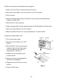
1. PREPARING THE ICEMAKER FOR LONG STORAGE ...................................... 68
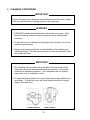
2. CLEANING PROCEDURE ................................................................................... 70
[a] CLEANING PROCEDURE ............................................................................. 71
[b] SANITIZING PROCEDURE ........................................................................... 73
3. MAINTENANCE ................................................................................................... 74
4
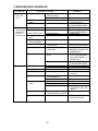
I. SPECIFICATIONS
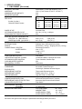
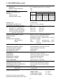
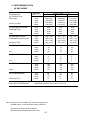
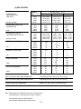
1. KM-1300SAF (Air-cooled)
AC SUPPLY VOLTAGE
AMPERAGE
MINIMUM CIRCUIT AMPACITY
MAXIMUM FUSE SIZE
APPROX. ICE PRODUCTION
PER 24 HR.
lbs./day ( kg./day )
Reference without *marks
208-230/60/1 ( 3 wire with neutral for 115 V )
12.6 A ( 5 min. freeze AT 104° F / WT 80° F )
20A
20A
Ambient
Water Temp. (°F)
Temp. (°F)
50
70
90
70
*1283 (582) 1238 (562) 1135 (515)
80
1249 (566) 1178 (535) 1053 (478)
90
1238 (562) *1129 (512) 1011 (458)
100
1203 (546) 1101 (500) *902 (409)
SHAPE OF ICE
ICE PRODUCTION PER CYCLE
APPROXIMATE STORAGE CAPACITY
ELECTRIC & WATER CONSUMPTION
ELECTRIC W ( KWH/100 lbs. )
WATER gal./24 HR. ( gal./100 lbs. )
EXTERIOR DIMENSIONS ( WxDxH )
EXTERIOR FINISH
WEIGHT
CONNECTIONS - ELECTRIC
- WATER SUPPLY
- DRAIN
Crescent Cube
30.1 lbs. ( 13.7 kg. ) 1440 pcs.
N/A
90° F / 70° F
70° F / 50° F
2235 ( 4.75 )
2180 ( 4.08 )
247 ( 21.9 )
479 ( 37.3 )
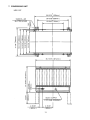
48" x 273¦8" x 273¦8" ( 1219 x 695 x 695 mm. )
Stainless steel, Galvanized Steel ( Rear )
Net 275 lbs. ( 125 kg. ) Shipping 315 lbs. ( 143 kg. )
Permanent Connection
Inlet 1¦2" FPT
Outlet 3¦4" FPT
3 8
¦ " ID Pipe
Float Switch
Hot Gas and Water, Thermistor and Timer
Timer Controlled, Overflow Pipe
N/A
Thermostat
Hermetic, Model CS14K6E-PFV
Air-cooled, Fin and Tube type
Vertical type, Stainless Steel and Copper
Thermostatic Expansion Valve
R404A, 3 lbs. 14 oz. ( 1750 g. )
High 467 PSIG, Low 230 PSIG
High Voltage Cut-out ( Internal )
Auto-reset Overload Protector ( Internal )
Auto-reset High Pressure Control Switch
Float Switch
N/A
Ice Storage Bin
VOLTAGE RANGE
187 - 264 V
AMBIENT TEMP.
45 - 100° F
WATER SUPPLY TEMP.
45 - 90° F
WATER SUPPLY PRESS.
10 - 113 PSIG
CUBE CONTROL SYSTEM
HARVESTING CONTROL SYSTEM
ICE MAKING WATER CONTROL
COOLING WATER CONTROL
BIN CONTROL SYSTEM
COMPRESSOR
CONDENSER
EVAPORATOR
REFRIGERANT CONTROL
REFRIGERANT CHARGE
DESIGN PRESSURE
P.C. BOARD CIRCUIT PROTECTION
COMPRESSOR PROTECTION
REFRIGERANT CIRCUIT PROTECTION
LOW WATER PROTECTION
ACCESSORIES - SUPPLIED
- REQUIRED
OPERATION CONDITIONS
We reserve the right to make changes in specifications and design without prior notice.
5
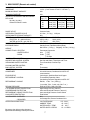
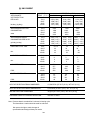
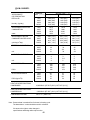
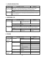
2. KM-1300SWF (Water-cooled)
AC SUPPLY VOLTAGE
AMPERAGE
MINIMUM CIRCUIT AMPACITY
MAXIMUM FUSE SIZE
APPROX. ICE PRODUCTION
PER 24 HR.
lbs./day ( kg./day )
Reference without *marks
208-230/60/1 ( 3 wire with neutral for 115 V )
9.7 A ( 5 MIN. Freeze AT 104° F / WT 80° F )
20A
20A
Ambient
Water Temp. (°F)
Temp. (°F)
50
70
90
*1252
(
568
)
1233
(
559
)
1176
( 533 )
70
80
1238 ( 561 ) 1209 ( 548 ) 1134 ( 514 )
90
1233 ( 559 ) *1188 ( 539 ) 1119 ( 508 )
100
1211 ( 549 ) 1172 ( 532 ) 1056 ( 479 )
SHAPE OF ICE
ICE PRODUCTION PER CYCLE
APPROXIMATE STORAGE CAPACITY
ELECTRIC & WATER CONSUMPTION
ELECTRIC W ( KWH/100 lbs. )
WATER gal./24 HR. ( gal./100 lbs. )
WATER COOLED CONDENSER
gal./24 hr. ( gal./100 lbs. )
EXTERIOR DIMENSIONS ( WxDxH )
EXTERIOR FINISH
WEIGHT
CONNECTIONS - ELECTRIC
- WATER SUPPLY
- DRAIN
Crescent Cube
30.1 lbs. ( 13.7 kg. ) 1440 pcs.
N/A
90° F / 70° F
70° F / 50° F
2050 ( 4.0 )
1975 ( 3.8 )
325 ( 27.4 )
623 ( 49.8 )
1521 ( 128 )
964 ( 77 )
CUBE CONTROL SYSTEM
HARVESTING CONTROL SYSTEM
ICE MAKING WATER CONTROL
COOLING WATER CONTROL
BIN CONTROL SYSTEM
COMPRESSOR
CONDENSER
EVAPORATOR
REFRIGERANT CONTROL
REFRIGERANT CHARGE
DESIGN PRESSURE
P.C. BOARD CIRCUIT PROTECTION
COMPRESSOR PROTECTION
REFRIGERANT CIRCUIT PROTECTION
LOW WATER PROTECTION
ACCESSORIES - SUPPLIED
- REQUIRED
OPERATION CONDITIONS
48" x 273¦8" x 273¦8" ( 1219 x 695 x 695 mm. )
Stainless steel, Galvanized Steel ( Rear )
Net 265 lbs. ( 120 kg. ) Shipping 315 lbs. ( 143 kg. )
Permanent Connection
1 2
1 2
Inlet
¦ " FPT
Condenser Inlet
¦ " FPT
3 4
3 8
¦ " FPT
Condenser Outlet ¦ " FPT
Outlet
3 8
¦ " ID Pipe
Float Switch
Hot Gas and Water, Thermistor and Timer
Timer Controlled, Overflow Pipe
Water Regulator
Thermostat
Hermetic, Model CS14K6E-PFV
Water-cooled, Tube in Tube type
Vertical type, Stainless Steel and Copper
Thermostatic ExpansionValve
R404A, 2 lb. 2 oz. ( 950 g. )
High 427 PSIG, Low 230 PSIG
High Voltage Cut-out ( Internal )
Auto-reset Overload Protector ( Internal )
Auto-reset High Pressure Control Switch
Float Switch
N/A
Ice Storage Bin
VOLTAGE RANGE
187 - 253 V
AMBIENT TEMP.
45 - 100° F
WATER SUPPLY TEMP.
45 - 90° F
WATER SUPPLY PRESS.
10 - 113 PSIG
We reserve the right to make changes in
specifications and design without prior notice.
6
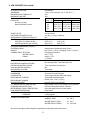
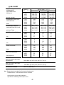
3. KM-1300SRF (Remote air-cooled)
AC SUPPLY VOLTAGE
AMPERAGE
MINIMUM CIRCUIT AMPACITY
MAXIMUM FUSE SIZE
APPROX. ICE PRODUCTION REFERENCE
PER 24 HR.
lbs./day ( kg./day )
Reference without *marks
208-230/60/1 ( 3 wire with neutral for 115 V )
14.5 A ( 5 min. freeze AT 104° F / WT 80° F )
20A
20A
Ambient
Water Temp. (°F)
Temp. (°F)
50
70
90
70
*1296 (588) 1248 (566) 1173 (532)
80
1260 (571) 1185 (538) 1105 (501)
1248 (566) *1133 (514) 1053 (478)
90
100
1230 (558) 1114 (505) *980 (445)
SHAPE OF ICE
ICE PRODUCTION PER CYCLE
APPROXIMATE STORAGE CAPACITY
ELECTRIC & WATER CONSUMPTION
ELECTRIC W ( KWH/100 lbs. )
WATER gal./24 HR. ( gal./100 lbs. )
EXTERIOR DIMENSIONS ( WxDxH )
EXTERIOR FINISH
WEIGHT
CONNECTIONS - ELECTRIC
- WATER SUPPLY
- DRAIN
Crescent Cube
30.1 lbs. ( 13.7 kg. ) 1440 pcs.
N/A
90°F/70°F
70°F/50°F
2350 ( 4.98 )
2300 ( 4.26 )
273 ( 24.1 )
456 ( 35.2 )
48" x 273¦8" x 273¦8" ( 1219 x 695 x 695 mm. )
Stainless steel, Galvanized Steel (Rear)
Net 255 lbs. ( 116 kg. ) Shipping 315 lbs. ( 143 kg. )
Permanent Connection
1 2
¦ " FPT
Inlet
3 4
Outlet ¦ " FPT
3 8
¦ " ID Pipe
Float Switch
Hot Gas and Water, Thermistor and Timer
Timer Controlled, Overflow Pipe
N/A
Thermostat
Hermetic, Model CS14K6E-PFV
Air-cooled remote, Condenser Unit URC-12F
recommended
Vertical type, Stainless Steel and Copper
Thermostatic Expansion Valve,
Condensing Pressure Regulator on URC-12F
R404A, 11 lbs. 7 oz. ( 5200 g. )
( Ice maker 7 lbs.; Cond. unit 4 lbs. 7 oz. )
HIGH 467 PSIG, LOW 230 PSIG
High Voltage Cut-out ( Internal )
Auto-reset Overload Protector ( Internal )
Auto-reset High Pressure Control Switch
Float Switch
N/A
Ice Storage Bin, Remote Condenser Unit
VOLTAGE RANGE
187 - 264 V
AMBIENT TEMP.
45 - 100° F
WATER SUPPLY TEMP.
45 - 90° F
WATER SUPPLY PRESS.
10 - 113 PSIG
CUBE CONTROL SYSTEM
HARVESTING CONTROL SYSTEM
ICE MAKING WATER CONTROL
COOLING WATER CONTROL
BIN CONTROL SYSTEM
COMPRESSOR
CONDENSER
EVAPORATOR
REFRIGERANT CONTROL
REFRIGERANT CHARGE
DESIGN PRESSURE
P.C. BOARD CIRCUIT PROTECTION
COMPRESSOR PROTECTION
REFRIGERANT CIRCUIT PROTECTION
LOW WATER PROTECTION
ACCESSORIES - SUPPLIED
- REQUIRED
OPERATION CONDITIONS
We reserve the right to make changes in
specifications and design without prior notice.
7
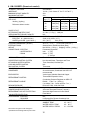
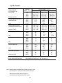
4. KM-1300SAF3 (Air-cooled)
AC SUPPLY VOLTAGE
AMPERAGE
MINIMUM CIRCUIT AMPACITY
MAXIMUM FUSE SIZE
APPROX. ICE PRODUCTION
PER 24 HR.
lbs./day ( kg./day )
Reference without *marks
208-230/60/3
7.8 A ( 5 min. freeze AT 104° F / WT 80° F )
20A
20A
Ambient
Water Temp. (°F)
Temp. (°F)
50
70
90
70
*1320 ( 599 ) 1257 ( 570 ) 1153 ( 523 )
80
1272 ( 577 ) 1174 ( 533 ) 1060 ( 481 )
90
1257 ( 570 ) *1105 ( 501 ) 993 ( 450 )
100
1230 ( 558 ) 1079 ( 489 ) *890 ( 404 )
SHAPE OF ICE
ICE PRODUCTION PER CYCLE
APPROXIMATE STORAGE CAPACITY
ELECTRIC & WATER CONSUMPTION
ELECTRIC W ( KWH/100 lbs. )
WATER gal./24 HR. ( gal./100 lbs. )
EXTERIOR DIMENSIONS ( WxDxH )
EXTERIOR FINISH
WEIGHT
CONNECTIONS - ELECTRIC
- WATER SUPPLY
- DRAIN
Crescent Cube
30.1 lbs. ( 13.7 kg. ) 1440 pcs.
N/A
90° F / 70° F
70° F / 50° F
2275 ( 5.0 )
2150 ( 3.9 )
292 ( 21.9 )
488 ( 37.3 )
3 8
3 8
48" x 27 ¦ " x 27 ¦ " ( 1219 x 695 x 695 mm. )
Stainless steel, Galvanized Steel ( Rear )
Net 275 lbs. ( 125 kg. ) Shipping 315 lbs. ( 143 kg. )
Permanent Connection
Inlet 1¦2" FPT
Outlet 3¦4" FPT
3 8
¦ " ID Pipe
Float Switch
Hot Gas and Water, Thermistor and Timer
Timer Controlled, Overflow Pipe
N/A
Thermostat
Hermetic, Model CS14K6E-TF5
Air-cooled, Fin and Tube type
Vertical type, Stainless Steel and Copper
Thermostatic ExpansionValve
R404A, 3 lbs. 14 oz. ( 1750 g. )
High 467 PSIG, Low 230 PSIG
High Voltage Cut-out; Low Voltage Cut-out (Internal)
Auto-reset Overload Protector ( Internal )
Auto-reset High Pressure Control Switch
Float Switch
N/A
Ice Storage Bin
VOLTAGE RANGE
187 - 253 V
AMBIENT TEMP.
45 - 100° F
WATER SUPPLY TEMP.
45 - 90° F
WATER SUPPLY PRESS.
10 - 113 PSIG
CUBE CONTROL SYSTEM
HARVESTING CONTROL SYSTEM
ICE MAKING WATER CONTROL
COOLING WATER CONTROL
BIN CONTROL SYSTEM
COMPRESSOR
CONDENSER
EVAPORATOR
REFRIGERANT CONTROL
REFRIGERANT CHARGE
DESIGN PRESSURE
P.C. BOARD CIRCUIT PROTECTION
COMPRESSOR PROTECTION
REFRIGERANT CIRCUIT PROTECTION
LOW WATER PROTECTION
ACCESSORIES - SUPPLIED
- REQUIRED
OPERATION CONDITIONS
We reserve the right to make changes in specifications and design without prior notice.
8
5. KM-1300SWF3 (Water-cooled)
AC SUPPLY VOLTAGE
AMPERAGE
MINIMUM CIRCUIT AMPACITY
MAXIMUM FUSE SIZE
APPROX. ICE PRODUCTION
PER 24 HR.
lbs./day ( kg./day )
Reference without *marks
SHAPE OF ICE
ICE PRODUCTION PER CYCLE
APPROXIMATE STORAGE CAPACITY
ELECTRIC & WATER CONSUMPTION
ELECTRIC W ( KWH/100 lbs. )
WATER gal./24 HR. ( gal./100 lbs. )
WATER COOLED CONDENSER
gal./24 hr. ( gal./100 lbs. )
EXTERIOR DIMENSIONS ( WxDxH )
EXTERIOR FINISH
WEIGHT
CONNECTIONS - ELECTRIC
- WATER SUPPLY
- DRAIN
CUBE CONTROL SYSTEM
HARVESTING CONTROL SYSTEM
ICE MAKING WATER CONTROL
COOLING WATER CONTROL
BIN CONTROL SYSTEM
COMPRESSOR
CONDENSER
EVAPORATOR
REFRIGERANT CONTROL
REFRIGERANT CHARGE
DESIGN PRESSURE
P.C. BOARD CIRCUIT PROTECTION
COMPRESSOR PROTECTION
REFRIGERANT CIRCUIT PROTECTION
LOW WATER PROTECTION
ACCESSORIES - SUPPLIED
- REQUIRED
OPERATION CONDITIONS
208-230/60/3
6.9 A ( 5 MIN. Freeze AT 104° F / WT 80° F )
20A
20A
Ambient
Water Temp. (°F)
Temp. (°F)
50
70
90
*1301 ( 590 ) 1273 ( 577 ) 1205 ( 547 )
70
80
1279 ( 580 ) 1235 ( 560 ) 1152 ( 523 )
1273 ( 577 ) *1204 ( 546 ) 1126 ( 511 )
90
1250 ( 567 ) 1186 ( 538 ) *1055 ( 479)
100
Crescent Cube
30.1 lbs. ( 13.7 kg. ) 1440 pcs.
N/A
90° F / 70° F
70° F / 50° F
2125 ( 4.0 )
2075 ( 3.8 )
342 ( 27.7 )
648 ( 49.8 )
1372 ( 112 )
885 ( 68 )
48" x 273¦8" x 273¦8" ( 1219 x 695 x 695 mm. )
Stainless steel, Galvanized Steel ( Rear )
Net 265 lbs. ( 120 kg. ) Shipping 315 lbs. ( 143 kg. )
Permanent Connection
1 2
Inlet
¦ " FPT
Condenser Inlet 1¦2" FPT
3 4
Outlet
¦ " FPT
Condenser Outlet 3¦8" FPT
3 8
¦ " ID Pipe
Float Switch
Hot Gas and Water, Thermistor and Timer
Timer Controlled, Overflow Pipe
Water Regulator
Thermostat
Hermetic, Model CS14K6E-TF5
Water-cooled, Tube in Tube type
Vertical type, Stainless Steel and Copper
Thermostatic ExpansionValve
R404A, 2 lb. 2 oz. ( 950 g. )
High 427 PSIG, Low 230 PSIG
High Voltage Cut-out, Low Voltage Cut-out ( Internal )
Auto-reset Overload Protector ( Internal )
Auto-reset High Pressure Control Switch
Float Switch
N/A
Ice Storage Bin
VOLTAGE RANGE
187 - 253 V
AMBIENT TEMP.
45 - 100° F
WATER SUPPLY TEMP.
45 - 90° F
WATER SUPPLY PRESS.
10 - 113 PSIG
We reserve the right to make changes in specifications and design without prior notice.
9
6. KM-1300SRF3 (Remote air-cooled)
AC SUPPLY VOLTAGE
AMPERAGE
MINIMUM CIRCUIT AMPACITY
MAXIMUM FUSE SIZE
APPROX. ICE PRODUCTION REFERENCE
PER 24 HR.
lbs./day ( kg./day )
Reference without *marks
SHAPE OF ICE
ICE PRODUCTION PER CYCLE
APPROXIMATE STORAGE CAPACITY
ELECTRIC & WATER CONSUMPTION
ELECTRIC W ( KWH/100 lbs. )
WATER gal./24 HR. ( gal./100 lbs. )
EXTERIOR DIMENSIONS ( WxDxH )
EXTERIOR FINISH
WEIGHT
CONNECTIONS - ELECTRIC
- WATER SUPPLY
- DRAIN
CUBE CONTROL SYSTEM
HARVESTING CONTROL SYSTEM
ICE MAKING WATER CONTROL
COOLING WATER CONTROL
BIN CONTROL SYSTEM
COMPRESSOR
CONDENSER
EVAPORATOR
REFRIGERANT CONTROL
REFRIGERANT CHARGE
DESIGN PRESSURE
P.C. BOARD CIRCUIT PROTECTION
COMPRESSOR PROTECTION
REFRIGERANT CIRCUIT PROTECTION
LOW WATER PROTECTION
ACCESSORIES - SUPPLIED
- REQUIRED
OPERATION CONDITIONS
208-230/60/3
10.8 A ( 5 min. freeze AT 104° F / WT 80° F )
20A
20A
Ambient
Water Temp. (°F)
Temp. (°F)
50
70
90
70
*1308 (593) 1282 (581) 1203 (546)
1288 (584) 1247 (566) 1145 (520)
80
90
1282 (581) *1218 (552) 1125 (510)
100
1252 (568) 1196 (543) *1039 (471)
Crescent Cube
30.1 lbs. ( 13.7 kg. ) 1440 pcs.
N/A
90°F/70°F
70°F/50°F
2300 ( 4.53 )2270 ( 4.17 )
252 ( 20.7 )
463 ( 35.4 )
48" x 273¦8" x 273¦8" ( 1219 x 695 x 695 mm. )
Stainless steel, Galvanized Steel (Rear)
Net 255 lbs. ( 116 kg. ) Shipping 315 lbs. ( 143 kg. )
Permanent Connection
1 2
Inlet
¦ " FPT
3 4
Outlet ¦ " FPT
3 8
¦ " ID Pipe
Float Switch
Hot Gas and Water, Thermistor and Timer
Timer Controlled, Overflow Pipe
N/A
Thermostat
Hermetic, Model CS14K6E-TF5
Air-cooled remote, Condenser Unit URC-12F
recommended
Vertical type, Stainless Steel and Copper
Thermostatic Expansion Valve,
Condensing Pressure Regulator on URC-12F
R404A, 11 lbs. 7 oz. ( 5200 g. )
( Ice maker 7 lbs.; Cond. unit 4 lbs. 7 oz. )
HIGH 467 PSIG, LOW 230 PSIG
High Voltage Cut-out ( Internal )
Auto-reset Overload Protector ( Internal )
Auto-reset High Pressure Control Switch
Float Switch
N/A
Ice Storage Bin, Remote Condenser Unit
VOLTAGE RANGE
187 - 264 V
AMBIENT TEMP.
45 - 100° F
WATER SUPPLY TEMP.
45 - 90° F
WATER SUPPLY PRESS.
10 - 113 PSIG
We reserve the right to make changes in
specifications and design without prior notice.
10
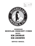
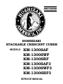
7. CONDENSING UNIT
URC-12F
11
SPECIFICATIONS
MODEL: URC-12F
EXTERIOR
Galvanized Steel
DIMENSIONS (W x D x H)
35 - 11/16” x 15-11/16” x 21-15/16”
(907.2 x 398 x 557.8 mm)
REFRIGERANT CHARGE
URC-12F
R404A 4 lbs. 7 oz. (2000 g)
WEIGHT
Net 80 lbs. (36 kg)
Shipping 87 lbs. (39 kg)
CONNECTIONS
REFRIGERANT
ELECTRICAL
One Shot Couplings (Aeroquip)
Permanent Connection
CONDENSER
Air-cooled
HEAD PRESSURE CONTROL
Condensing Pressure Regulator
AMBIENT CONDITION
Min. -20°F - Max. +122°F
(-29°C to +50°C)
Outdoor use
12
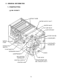
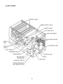
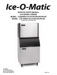
II. GENERAL INFORMATION
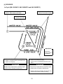
1. CONSTRUCTION
[a] KM-1300SAF/3
13
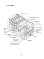
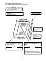
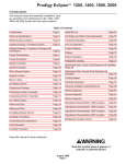
[b] KM-1300SWF/3
14
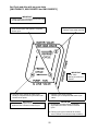
[c] KM-1300SRF/3
15
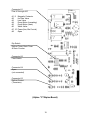
2. CONTROLLER BOARD
[a] SOLID-STATE CONTROL
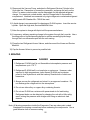
1) A HOSHIZAKI exclusive solid-state control is employed in KM-1300SAF,
KM-1300SWF, KM-1300SRF, KM-1300SAF3, KM-1300SWF3 and KM-1300SRF3
Stackable Crescent Cubers.
2) A Printed Circuit Board (hereafter called “Controller Board”) includes a stable and
high quality control system.
3) All models are pretested and factory-adjusted.
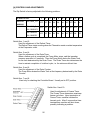
[b] CONTROLLER BOARD
CAUTION
1. Fragile, handle very carefully.
2. A controller board contains integrated circuits, which are susceptible to
failure due to static discharge. It is especially important to touch the
metal part of the unit when handling or replacing the board.
3. Do not touch the electronic devices on the board or the back of the
board to prevent damage to the board.
4. Do not change wiring and connections. Especially, never misconnect
K3, K4 and K5, because the same connector is used for the Thermistor
and Float Switch. K4 is not connected.
5. Do not fix the electronic devices or parts on the board in the field.
Always replace the whole board assembly when it goes bad.
6. Do not short out power supply to test for voltage.
16
KM-1300S_F/3 models use either the Alpine Controller Board (orange):
PART NUMBER
TYPE
2U0127-01
MY9KM910 (Alpine)
MY9KM91B (Alpine)
OR the Control Products Board (green):
PART NUMBER
2A0836-01
TYPE
HOSHIZAKI 001 (Control Products - 8 Pin)
OR the Control Products Improved “E” Board (green):
PART NUMBER
2A1410-01
TYPE
HOS-001A (Control Products - 10 Pin)
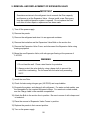
Features of All Three Controller Boards
(1) Maximum Water Supply Period - 6 minutes
Water Solenoid Valve opening, in the Defrost (Harvest) Cycle, is limited by
maximum period of the defrost timer. The Water Valve cannot remain open
longer than the maximum period. The Water Valve can close in less than the
maximum period if the defrost cycle is completed.
(2) Defrost Timer
The defrost cycle starts when the Float Switch opens and completes the
freeze cycle. But the Defrost Timer does not start counting until the Thermistor senses 48°F at the Evaporator outlet. The period from the end of the
freeze cycle up to the point of the Thermistor's sensing varies depending on
the ambient and water temperatures.
(3) High Temperature Safety - 127 ± 7°F
The temperature of the suction line in the refrigerant circuit is limited by the
High Temperature Safety.
During the defrost cycle the Evaporator temperature rises. The Thermistor
senses 48°F and starts the Defrost Timer. After the Defrost Timer counts
down to zero, the normal freeze cycle begins. If the Evaporator temperature
continues to rise, the Thermistor will sense the rise in temperature and at 127
± 7°F the Thermistor operates the High Temperature Safety.
17
This High Temperature Safety shuts down the circuit and the icemaker automatically stops. To reset the safety, turn the power off and back on again.
This High Temperature Safety protects the unit from excessive temperature.
(4) Low Water Safety
If the Pump Motor is operated without water, the mechanical seal can fail. To prevent this type of failure, the Controller Board checks the position of the Float Switch
at the end of the initial one minute water fill cycle and at the end of each defrost
cycle.
If the Float Switch is in the up position (electrical circuit closed), the Controller
Board changes to the ice making cycle. If the Float Switch is in the down position
(electrical circuit open), the Controller Board changes to a one minute water fill
cycle before starting the ice making cycle. This method allows for a Low Water
Safety shut down to protect the Water Pump from mechanical seal failure.
For water-cooled model, if the water is shut off, the unit is protected by the High
Pressure Switch.
(5) High Voltage Cut-out
The maximum allowable supply voltage of this icemaker is limited by the High
Voltage Cut-out.
If miswiring causes excessive voltage on the Controller Board, the High Voltage
Cut-out shuts down the circuit in 3 seconds and the icemaker automatically stops.
When the proper supply voltage is resumed, the icemaker automatically starts
running again.
18
Connector K1
Pins #1 through #10
#1, 9
#2
#3
#4
#5
#6
#7, 10
#8
Magnetic Contactor
Hot Gas Valve
Line Valve
Pump Motor (icemaking)
Pump Motor (drain)
Water Valve
Power (line, Bin Control)
Open
Dip Switch
Defrost Timer, Drain Timer
& Drain Counter
Connector K5
Float Switch
Connector K4
Open
(not connected)
Connector K3
Defrost Control
(Thermistor)
(Alpine “C”/Alpine Board)
19
Features of Control Products “E” Controller Board
The “E” board includes LED lights and audible alarm safeties. The red LED indicates proper control
voltage and will remain on unless a control voltage problem occurs. At startup a 5 second delay
occurs while the board conducts an internal timer check. A short beep occurs when the power
switch is turned ON or OFF.
The green LED’s 1-4 represent the corresponding relays and energize and sequence 5 seconds
from initial startup as follows:
Sequence Step
1 Minute Fill Cycle
Harvest Cycle
Freeze Cycle
Reverse Pump Out
LED’s on
LED4
LED1, 4, & 2
LED1
LED1, 3, & 2
Length: Min.
2 min.
5 min.
10 sec.
Max.
20 min.
60 min.
20 sec.
Avg.
60 sec.
3-5 min.
30-35 min.
Factory set.
{LED 1 – Comp; LED 2 - HGV/CFM; LED 3 – PM; LED 4 - WV}
The built in safeties shut down the unit and have alarms as follows:
1 beep every 3 sec. = High Evaporator Temperature >127 ° F.
Check for defrost problem (stuck HGV or relay), hot water entering unit, stuck headmaster, or
shorted thermistor.
2 beeps every 3 sec. = Defrost Back Up Timer. Defrost >20 minutes.
Orange LED marked 20 MIN energizes.
Check for open thermistor, HGV not opening, TXV leaking by, low charge, or inefficient compressor.
3 beeps every 3 sec. = Freeze Back Up Timer. Freeze > 60 minutes.
Yellow LED marked 60 MIN energizes.
Check for F/S stuck closed (up), WV leaking by, HGV leaking by, TXV not feeding properly, low
charge, or inefficient compressor.
To manually reset the above safeties, depress white alarm reset button with the power supply ON.
6 beeps every 3 sec. = Low Voltage. Voltage is 92 Vac or less.
7 beeps every 3 sec. = High Voltage. Control voltage > 147Vac ±5%.
The red LED will de-energize if voltage protection operates.
The voltage safety automatically resets when voltage is corrected.
The Output Test switch “S3” provides a relay sequence test. With power OFF, place S3 on and
switch power to ICE. The correct lighting sequence should be none, 2, 3, 4, 1, & 4, normal sequence every 5 seconds. S3 should remain in the “OFF” position for normal operation.
The application switch located between relay X3 & X4 must be set to match the original board
application. Place this switch in the ALP position if there is no white wire supplied to the K1 connector. If there is a white wire, place the switch in the C position. If this switch is placed in the wrong
position either the compressor contactor will remain energized with the control switch OFF or the unit
will not start.
The dip switches should be adjusted per the adjustment chart published in the Tech Specs book. 7 &
8 must remain in the OFF position.
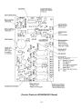
20
(Control Products HOSHIZAKI001 Board)
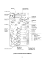
21
(Control Products HOS-001A Board)
22
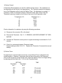
[c] SEQUENCE
1st Cycle [KM-1300SAF/3, KM-1300SWF/3 and KM-1300SRF/3]
3. Thermistor reads 48°F.
Defrost Timer starts counting.
1. Unit energized and Control Switch to “ICE”
position. Water supply cycle starts.
2. After 1 minute.
Defrost cycle starts.
IMPORTANT
Water Valve
opening is limited
to 6 minutes.
5. After the first 5 minutes in freeze cycle.
Ready to complete freeze cycle when Float
Switch circuit opens.
4. Defrost Timer stops counting.
Defrost cycle is completed and freeze cycle
starts.
IMPORTANT
Board never accepts freeze completion signal
within the first 5 minutes in freeze cycle.
IMPORTANT
1. Board never accepts defrost completion signal
within the first 2 minutes in defrost cycle.
2. Defrost cycle time is limited to 20 minutes even
if Defrost Timer does not stop counting.
23
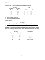
2nd Cycle and after with pump drain
[KM-1300SAF/3, KM-1300SWF/3 and KM-1300SRF/3]
IMPORTANT
Freeze cycle time is limited to 60 minutes even
if Float Switch does not open.
2. Drain timer stops counting.
Pump drain is completed
1. Float Switch opens and signals to complete
freeze cycle.
Drain timer starts counting.
3. Thermistor reads 48° F.
Defrost Timer starts
counting.
IMPORTANT
Water Valve
opening is limited to 6
minutes.
&
5. After the first 5 minutes in freeze cycle.
Ready to complete freeze cycle when Float
Switch circuit opens.
4. Defrost Timer stops counting.
Defrost cycle is completed and freeze cycle
starts.
IMPORTANT
Board never accepts freeze completion signal
within the first 5 minutes in freeze cycle.
IMPORTANT
1. Board never accepts defrost completion
signal within the first 2 minutes in defrost
cycle.
2. Defrost cycle time is limited to 20 minutes
even if Defrost Timer does not stop counting.
24
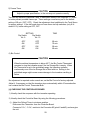
2nd Cycle and after with no pump drain
[KM-1300SAF/3, KM-1300SWF/3 and KM-1300SRF/3]
IMPORTANT
Freeze cycle time is limited to 60 minutes even
if Float Switch does not open.
2. Thermistor reads 48° F.
Defrost Timer starts counting.
1. Float Switch opens and signals to complete
freeze cycle.
IMPORTANT
Water Valve
opening is limited to 6
minutes.
4. After the first 5 minutes in freeze cycle.
Ready to complete freeze cycle when Float
Switch circuit opens.
IMPORTANT
Board never accepts freeze completion signal
within the first 5 minutes in freeze cycle.
3. Defrost Timer stops counting.
Defrost cycle is completed and freeze cycle
starts.
IMPORTANT
1. Board never accepts defrost completion
signal within the first 2 minutes in defrost
cycle.
2. Defrost cycle time is limited to 20 minutes
even if Defrost Timer does not stop counting.
25
[d] CONTROLS AND ADJUSTMENTS
The Dip Switch is factory-adjusted to the following positions:
DIP SWITCH NO.
2U0127-01
KM-1300S_F/3
1
2
3
4
5
6
OFF OFF ON
ON
ON
OFF OFF ON
ON
OFF OFF ON
ON
7
8
9
10
ON
OFF OFF NA
NA
ON
ON
OFF OFF OFF OFF
ON
ON
OFF OFF ON
2A0836-01
2A1410-01
KM-1300S_F,
KM-1300SWF3
KM-1300SAF3
OFF
KM-1300SRF3
Switch Nos. 1 and 2:
Used for adjustment of the Defrost Timer.
The Defrost Timer starts counting when the Thermistor reads a certain temperature
at the Evaporator outlet.
Switch Nos. 3 and 4:
Used for adjustment of the Drain Timer.
When a freeze cycle is completed, the Pump Motor stops, and the icemaker
resumes operation in 2 seconds. Then the Pump Motor drains the Water Tank
for the time determined by the Drain Timer. The Drain Timer also determines the
time to restrain completion of a defrost cycle, i.e. the minimum defrost time.
Switch Nos. 5 and 6:
Used for adjustment of the Drain Counter.
The Pump Motor drains the Water Tank at the frequency determined by the Drain
Counter.
Switch Nos. 7 and 8:
Used only for checking the Controller Board. Usually set in OFF position.
Switch Nos. 9 and 10:
Used for adjustment of Freeze Timer.
The Freeze Timer determines maximum
freeze cycle time. Upon termination of
Freeze Timer, machine initiates the
harvest cycle. After 2 consecutive timer
terminations, machine will shut down,
possibly indicating a problem.
26
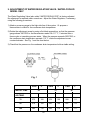
1) Defrost Control
A thermistor (Semiconductor) is used for a defrost control sensor. The resistance varies depending on the Suction Line temperatures. The Thermistor detects the temperature of the Evaporator outlet to start the Defrost Timer. No adjustment is required. If
necessary, check for resistance between Thermistor leads, and visually check the
Thermistor mounting, located on the Suction Line next to the Evaporator outlet.
Temperature (°F)
0
10
32
50
70
90
Resistance (kΩ)
14.401
10.613
6.000
3.871
2.474
1.633
Check a thermistor for resistance by using the following procedures.
(i) Disconnect the connector K3 on the board.
(ii) Remove the Thermistor. See “V. 11. REMOVAL AND REPLACEMENT OF THERMISTOR.”
(iii) Immerse the Thermistor sensor portion in a glass containing ice and water for 2 or 3
minutes.
(iv) Check for a resistance between Thermistor leads.
Normal reading is within 3.5 to 7 kΩ. Replace the Thermistor if it exceeds the normal
reading.
2) Defrost Timer
No adjustment is required under normal use, as the Defrost Timer is adjusted to the
suitable position. However, if necessary when all the ice formed on the Evaporator
does not fall into the bin in the harvest cycle, adjust the Defrost Timer to a longer setting
by adjusting the Dip Switch (No. 1 & 2) on the Controller Board.
SETTING
Dip Switch
Dip Switch
No. 1
No. 2
OFF
ON
OFF
ON
TIME
OFF
OFF
ON
ON
60 seconds
90 seconds
120 seconds
180 seconds
27
3) Drain Timer
The Drain Timer is factory-adjusted, and no adjustment is required.
SETTING
Dip Switch
Dip Switch
No. 3
No. 4
OFF
ON
OFF
ON
TIME
T1
OFF
OFF
ON
ON
10
10
10
20
T2
seconds
seconds
seconds
seconds
150
180
120
180
seconds
seconds
seconds
seconds
T1: Time to drain the Water Tank
T2: Time to restrain defrost completion
4) Drain Counter
CAUTION
Do not adjust the Drain Counter, or the Evaporator may freeze up.
The Drain Counter is factory-adjusted to drain the Water Tank every 10 cycles, and no
adjustment is required. However, where water quality is bad and the icemaker needs a
pump drain more often, the Drain Counter can be adjusted as shown in the table below:
SETTING
Dip Switch
Dip Switch
No. 5
No. 6
OFF
ON
OFF
ON
OFF
OFF
ON
ON
FREQUENCY
every cycle
every 2 cycles
every 5 cycles
every 10 cycles
28
5) Freeze Timer
CAUTION
Adjust to proper specification, or the unit may not operate correctly.
Two new dip switches numbered 9 and 10 have been added to the improved “E” board
to better prevent possible freeze ups. These settings come factory set to the default
setting of 60 min. (OFF, OFF). Check the adjustment chart published in the Tech Specs
for proper settings. If the old board does not have these two dip switches, (only 8 instead of 10), leave setting as OFF, OFF.
SETTING
Dip Switch
Dip Switch
No. 9
No. 10
OFF
ON
OFF
ON
TIME
OFF
OFF
ON
ON
60 min.
70 min.
50 min.
60 min.
6) Bin Control
CAUTION
When the ambient temperature is below 45°F, the Bin Control Thermostat
operates to stop the icemaker even if the Ice Storage Bin is empty. When
the Thermostat is set in the prohibited range, the icemaker operates
continuously even if the Ice Storage Bin is filled with ice. Setting in the
prohibited range might cause severe damage to the icemaker resulting in
failure.
No adjustment is required under normal use, as the Bin Control is factory-adjusted.
Adjust it, if necessary, so that the icemaker stops automatically within 10 seconds after
ice contacts the Bin Control Thermostat Bulb.
[e] CHECKING THE CONTROLLER BOARD
1) Visually check the sequence with the icemaker operating.
2) Visually check the Controller Board by using the following procedures.
(i) Adjust the Defrost Timer to minimum position.
Disconnect the Thermistor from the Controller Board.
Connect a 1.5 kΩ - 3.5 kΩ resistor to the Connector K3 (pins #1 and #2), and energize
the unit.
29
After the 1 minute ± 5 second water supply cycle and the 2 minute ± 10 second defrost
cycle, the unit should start the freeze cycle.
(ii) After the above step (i), disconnect the Float Switch leads from the Controller Board
within the first 5 minutes of the freeze cycle.
The unit should go into the defrost cycle after the first 5 minutes ± 20 seconds of the
freeze cycle.
(iii) Reconnect the Float Switch Connector to the Controller Board. After the first 5
minutes of the freeze cycle, disconnect the Float Switch leads from the Controller
Board.
At this point, the unit should start the defrost cycle.
(iv) After Step (iii), de-energize the unit and confirm that the Defrost Timer is in the
minimum position. Disconnect the resistor from the Controller Board, and energize the unit.
After the 1 minute water supply cycle, the defrost cycle starts.
Re-connect a 1.5 kΩ - 3.5 kΩ resistor to the Connector K3 (pins #1 and #2) after
the first 2 minutes of the defrost cycle. The unit should start the freeze cycle after
1 minute ± 5 seconds from the resistor
connection.
[ALPINE BOARD ONLY]
3) Check the Controller Board by using test program of the Alpine Controller Board
(next page).
(i) Disconnect the Connector K1 from the Controller Board. Set the Dip Switch No. 7
and 8 on the Controller Board to the “ON” position, and energize the unit.
(ii) The current flows to each Relay (from X1 to X4) one after another every time the
float is raised and the contacts close. See the following chart, and check “OPEN”
and “CLOSE” of Pins of the Connector K1 at each step.
(iii) If the checks are completed, turn off the icemaker, plug the Connector K1 into the
Controller Board as before, and set the Dip Switch No. 7 and 8 to the “OFF” position.
[CONTROL PRODUCTS BOARD ONLY]
The Output Test Switch “S3” provides a relay sequence test. With power OFF, place
S3 on and switch power to ICE. The correct lighting sequence should be none, 2, 3, 4,
1, and 4, normal sequence every 5 seconds. S3 should remain in the “OFF” position
for normal operation.
30
• TEST PROGRAM OF ALPINE CONTROLLER BOARD
31
III. TECHNICAL INFORMATION
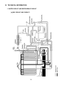
1. WATER CIRCUIT AND REFRIGERANT CIRCUIT
[a] KM-1300SAF, KM-1300SAF3
32
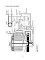
[b] KM-1300SWF, KM-1300SWF3
33
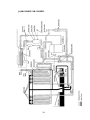
[c] KM-1300SRF, KM-1300SRF3
34
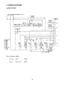
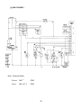
2. WIRING DIAGRAMS
[a] KM-1300SAF
Note: Pressure Switch
Cut-out
412 +21.3
0
PSIG
Cut-in
327 ± 21.3
PSIG
35
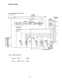
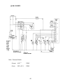
[b] KM-1300SWF
Note: Pressure Switch
Cut-out
384 +21.3
0
PSIG
Cut-in
284.5 ± 21.3
PSIG
36
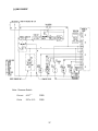
[c] KM-1300SRF
Note: Pressure Switch
Cut-out
412 +21.3
0
PSIG
Cut-in
327 ± 21.3
PSIG
37
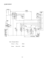
[d] KM-1300SAF3
Note: Pressure Switch
Cut-out
412 +21.3
0
PSIG
Cut-in
327 ± 21.3
PSIG
38
[e] KM-1300SWF3
Note: Pressure Switch
Cut-out
384 +21.3
0
PSIG
Cut-in
284 ± 21.3
PSIG
39
[f] KM-1300SRF3
Note: Pressure Switch
Cut-out
412 +21.3
0
PSIG
Cut-in
327 ± 21.3
PSIG
40
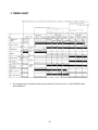
3. TIMING CHART
*1
The icemaker does not complete a defrost cycle in the first 2 or 3 minutes. See “II. 2. [d] CONTROLS AND
ADJUSTMENTS.”
41
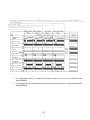
*1
The Pump Motor waits for 2 seconds before starting a drain cycle. See “II. 2. [d] CONTROLS AND
ADJUSTMENTS.”
*2
The icemaker does not complete a defrost cycle in the first 2 or 3 minutes. See “II. 2. [d] CONTROLS AND
ADJUSTMENTS.”
42
4. PERFORMANCE DATA
[a] KM-1300SAF
APPROXIMATE
ICE PRODUCTION
PER 24 HR.
lbs./day (kg./day)
APPROXIMATE ELECTRIC
CONSUMPTION
watts
APPROXIMATE WATER
CONSUMPTION PER 24 HR.
gal./day (m3/day)
FREEZING CYCLE TIME
min.
HARVEST CYCLE TIME
min.
HEAD PRESSURE
PSIG
SUCTION PRESSURE
PSIG (kg/cm2G)
TOTAL HEAT OF REJECTION
AMBIENT
TEMP. ( °F/°C )
50/10
70/21
80/27
90/32
100/38
*1283 (582)
1249 (566)
1238 (562)
1203 (546)
70/21
80/27
90/32
100/38
*2180
2192
2196
2202
70/21
80/27
90/32
100/38
*479 ( 1.82 )
428 ( 1.62 )
411 ( 1.56 )
414 ( 1.57 )
WATER TEMP. ( °F/°C )
70/21
90/32
1238 (562)
1178 (535)
*1129 (512)
1101 (500)
2196
2217
*2235
2241
411 ( 1.56 )
322 ( 1.22 )
*247 ( 0.94 )
237 ( 0.90 )
1135 (515)
1053 (478)
1011 (458)
* 902 (409)
2220
2243
2261
*2284
358 ( 1.36 )
291 ( 1.10 )
205 ( 0.78 )
167 ( 0.63 )
70/21
80/27
90/32
100/38
*30
32
32
33
32
35
*37
38
36
39
41
44
70/21
80/27
90/32
100/38
*4.5
4
4
4
4
3
*2.2
2
4
3
2
2
70/21
80/27
90/32
100/38
*255
268
273
277
273
296
*315
320
296
318
338
360
70/21
80/27
90/32
100/38
*45
46
47
47
47
49
*51
51
49
51
53
55
19,800 Btu/h [AT 90°F (32°C) / WT 70°F (21°C)]
Note: Pressure data is recorded first 5 minutes in freezing cycle.
The data without * marks should be used for reference.
We reserve the right to make changes in
specifications and design without prior notice.
43
[b] KM-1300SWF
APPROXIMATE
ICE PRODUCTION
PER 24 HR.
AMBIENT
TEMP. ( °F/°C )
lbs./day (kg./day)
APPROXIMATE ELECTRIC
CONSUMPTION
watts
APPROXIMATE WATER
CONSUMPTION PER 24 HR.
gal./day (m3/day)
FREEZING CYCLE TIME
min.
HARVEST CYCLE TIME
min.
HEAD PRESSURE
PSIG
SUCTION PRESSURE
PSIG
50/10
WATER TEMP. ( °F/°C )
70/21
90/32
70/21
80/27
90/32
100/38
*1252 ( 568 )
1238 ( 561 )
1233 ( 559 )
1211 ( 549 )
1233 ( 559 )
1209 ( 548 )
*1188 ( 539 )
1172 ( 532 )
70/21
80/27
90/32
100/38
*1975
1992
1997
2012
1997
2026
*2050
2062
70/21
80/27
90/32
100/38
*1587 ( 6.01 )
1645 ( 6.23 )
1663 ( 6.30 )
1750 ( 6.62 )
1663 (
1763 (
*1846 (
1910 (
6.30 )
6.67 )
6.99 )
7.23 )
1176 ( 533 )
1134 ( 514 )
1119 ( 508 )
*1056 ( 479 )
2043
2081
2102
*2150
1890 (
2058 (
2117 (
*2365 (
7.15 )
7.79 )
8.01 )
8.95 )
70/21
80/27
90/32
100/38
*31.75
32
32
33
32
33
*33.6
34
35
36
36
*39
70/21
80/27
90/32
100/38
*4.3
4
4
4
4.0
3
*2.25
2
3
3
2
*2
70/21
80/27
90/32
100/38
*275
277
278
282
278
282
*285
288
288
295
297
*308
70/21
80/27
90/32
100/38
*47
47
48
48
48
48
*49
49
49
49
50
*51
HEAT OF REJECTION FROM CONDENSER
15,560 BTU/h [AT 90°F (32°C) / WT 70°F (21°C)]
HEAT OF REJECTION FROM COMPRESSOR
2,650 Btu/h [AT 90°F (32°C) / WT 70°F (21°C)]
WATER FLOW FOR CONDENSER
88 gal./h [AT 100°F (38°C) / WT 90°F (32°C)]
PRESSURE DROP OF COOLING WATER LINE
less than 10 PSIG
Note: Pressure data is recorded first 5 minutes in freezing cycle.
The data without * marks should be used for reference.
We reserve the right to make changes in
specifications and design without prior notice.
44
[c] KM-1300SRF
APPROXIMATE
ICE PRODUCTION
PER 24 HR.
lbs./day (kg./day)
APPROXIMATE ELECTRIC
CONSUMPTION
watts
APPROXIMATE WATER
CONSUMPTION PER 24 HR.
gal./day (m3/day)
FREEZING CYCLE TIME
min.
HARVEST CYCLE TIME
min.
HEAD PRESSURE
PSIG
SUCTION PRESSURE
PSIG (kg/cm2G)
AMBIENT
TEMP. ( °F/°C )
50/10
70/21
80/27
90/32
100/38
*1296 (588)
1260 (571)
1248 (566)
1230 (558)
70/21
80/27
90/32
100/38
*2300
2311
2315
2321
70/21
80/27
90/32
100/38
*456 ( 1.73 )
415 ( 1.58 )
402 ( 1.52 )
401 ( 1.52 )
WATER TEMP. ( °F/°C )
70/21
90/32
1248 (566)
1185 (538)
*1133 (514)
1114 (505)
2315
2334
*2350
2356
402 ( 1.52 )
332 ( 1.26 )
*273 ( 1.03 )
263 ( 1.00 )
2339
2360
2376
*2400
353 ( 1.34 )
296 ( 1.12 )
230 ( 0.87 )
191 ( 0.72 )
70/21
80/27
90/32
100/38
*29
30
30
31
30
31
*32
33
33
35
36
40
70/21
80/27
90/32
100/38
*5
4
4
4
4
3
*2.2
2
4
3
2
2
70/21
80/27
90/32
100/38
*220
229
232
235
232
247
*260
264
247
262
276
290
70/21
80/27
90/32
100/38
*45
46
47
47
46
48
*50
51
49
51
53
55
HEAT OF REJECTION FROM
CONDENSER
18,300 Btu/h [AT 90°F (32°C) / WT 70°F (21°C)]
HEAT OF REJECTION FROM
COMPRESSOR
2,910 Btu/h [AT 90°F (32°C) / WT 70°F (21°C)]
CONDENSER VOLUME
1173 (532)
1105 (501)
1053 (478)
* 980 (445)
132 cu. in. ( URC-12F )
Note: Pressure data is recorded first 5 minutes in freezing cycle.
The data without * marks should be used for reference.
We reserve the right to make changes in
specifications and design without prior notice.
45
[d] KM-1300SAF3
APPROXIMATE
ICE PRODUCTION
PER 24 HR.
lbs./day (kg./day)
APPROXIMATE ELECTRIC
CONSUMPTION
watts
APPROXIMATE WATER
CONSUMPTION PER 24 HR.
gal./day (m3/day)
FREEZING CYCLE TIME
min.
HARVEST CYCLE TIME
min.
HEAD PRESSURE
PSIG
SUCTION PRESSURE
PSIG (kg/cm2G)
TOTAL HEAT OF REJECTION
AMBIENT
TEMP. ( °F/°C )
50/10
70/21
80/27
90/32
100/38
*1320 ( 599 )
1272 ( 577 )
1257 ( 570 )
1230 ( 558 )
70/21
80/27
90/32
100/38
*2150
2178
2187
2192
70/21
80/27
90/32
100/38
*488 ( 1.85 )
445 ( 1.68 )
431 ( 1.63 )
435 ( 1.65 )
WATER TEMP. ( °F/°C )
70/21
90/32
1257 ( 570 )
1174 ( 533 )
*1105 ( 501 )
1079 ( 489 )
2187
2235
*2275
2284
431 ( 1.63 )
355 ( 1.34 )
*292 ( 1.11 )
285 ( 1.08 )
1153 ( 523 )
1060 ( 481 )
993 ( 450 )
*890 ( 404 )
2228
2271
2314
*2350
388 ( 1.47 )
333 ( 1.26 )
260 ( 0.99 )
231 ( 0.87 )
70/21
80/27
90/32
100/38
*30
32
32
33
32
35
*37.4
38
36
39
41
44.75
70/21
80/27
90/32
100/38
*4
4
4
4
3
3
*2.1
2
3
3
2
2
70/21
80/27
90/32
100/38
*255
270
274
277
274
299
*320
325
296
318
341
360
70/21
80/27
90/32
100/38
*47
48
48
49
48
50
*52
52
50
52
54
55
18,130 Btu/h [AT 90°F (32°C) / WT 70°F (21°C)]
Note: Pressure data is recorded first 5 minutes in freezing cycle.
The data without * marks should be used for reference.
We reserve the right to make changes in
specifications and design without prior notice.
46
[e] KM-1300SWF3
APPROXIMATE
ICE PRODUCTION
PER 24 HR.
AMBIENT
TEMP. ( °F/°C )
lbs./day (kg./day)
APPROXIMATE ELECTRIC
CONSUMPTION
watts
APPROXIMATE WATER
CONSUMPTION PER 24 HR.
gal./day (m3/day)
FREEZING CYCLE TIME
min.
HARVEST CYCLE TIME
min.
HEAD PRESSURE
PSIG
SUCTION PRESSURE
PSIG
70/21
80/27
90/32
100/38
50/10
*1301 ( 590 )
1279 ( 580 )
1273 ( 577 )
1250 ( 567 )
70/21
80/27
90/32
100/38
*2075
2086
2090
2101
70/21
80/27
90/32
100/38
*1533 ( 5.80 )
1574 ( 5.96 )
1586 ( 6.00 )
1664 ( 6.30 )
WATER TEMP. ( °F/°C )
70/21
90/32
1273 ( 577 )
1235 ( 560 )
*1204 ( 546 )
1186 ( 538 )
2090
2109
*2125
2134
1586 (
1656 (
*1715 (
1769 (
6.00 )
6.28 )
6.49 )
6.70 )
1205 ( 547 )
1152 ( 523 )
1126 ( 511 )
*1055 ( 479 )
2124
2151
2164
*2200
1776 (
1911 (
1945 (
*2158 (
6.72 )
7.23 )
7.36 )
8.17 )
70/21
80/27
90/32
100/38
*30.2
31
31
32
31
32
*32.75
33
33
34
35
*36.5
70/21
80/27
90/32
100/38
*4.2
4
4
4
4
3
*2.2
2
3
3
2
*2
70/21
80/27
90/32
100/38
*270
273
274
277
274
280
*285
287
284
291
295
*305
70/21
80/27
90/32
100/38
*48
49
49
49
49
50
*51
51
50
51
52
*53
HEAT OF REJECTION FROM CONDENSER
15,450 Btu/h [AT 90°F (32°C) / WT 70°F (21°C)]
HEAT OF REJECTION FROM COMPRESSOR
2,560 Btu/h [AT 90°F (32°C) / WT 70°F (21°C)]
WATER FLOW FOR CONDENSER
88 gal./h [AT 100°F (38°C) / WT 90°F (32°C)]
PRESSURE DROP OF COOLING WATER LINE
less than 10 PSIG
Note: Pressure data is recorded first 5 minutes in freezing cycle.
The data without * marks should be used for reference.
We reserve the right to make changes in
specifications and design without prior notice.
47
[f] KM-1300SRF3
APPROXIMATE
ICE PRODUCTION
PER 24 HR.
lbs./day (kg./day)
APPROXIMATE ELECTRIC
CONSUMPTION
watts
APPROXIMATE WATER
CONSUMPTION PER 24 HR.
gal./day (m3/day)
FREEZING CYCLE TIME
min.
HARVEST CYCLE TIME
min.
HEAD PRESSURE
PSIG
SUCTION PRESSURE
PSIG (kg/cm2G)
AMBIENT
TEMP. ( °F/°C )
50/10
70/21
80/27
90/32
100/38
*1308 (593)
1288 (584)
1282 (581)
1252 (568)
70/21
80/27
90/32
100/38
*2270
2277
2279
2303
70/21
80/27
90/32
100/38
*463 ( 1.75 )
416 ( 1.58 )
401 ( 1.52 )
405 ( 1.53 )
70/21
80/27
90/32
100/38
*30
30
31
31
70/21
80/27
90/32
100/38
*4.8
4
4
4
WATER TEMP. ( °F/°C )
70/21
90/32
1282 (581)
1247 (566)
*1218 (552)
1196 (543)
2279
2290
*2300
2316
401 ( 1.52 )
320 ( 1.21 )
*252 ( 0.95 )
244 ( 0.92 )
2332
2367
2368
*2430
356 ( 1.35 )
296 ( 1.12 )
218 ( 0.82 )
187 ( 0.72 )
31
32
*33
34
33
35
36
39
4
3
*2.2
2
4
3
2
2
70/21
80/27
90/32
100/38
*230
239
242
246
242
257
*270
274
259
275
288
305
70/21
80/27
90/32
100/38
*50
51
51
52
51
52
*53
54
53
55
56
58
HEAT OF REJECTION FROM
CONDENSER
16,600 Btu/h [AT 90°F (32°C) / WT 70°F (21°C)]
HEAT OF REJECTION FROM
COMPRESSOR
2,500 Btu/h [AT 90°F (32°C) / WT 70°F (21°C)]
CONDENSER VOLUME
1203 (546)
1145 (520)
1125 (510)
*1039 (471)
132 cu. in. ( URC-12F )
Note: Pressure data is recorded first 5 minutes in freezing cycle.
The data without * marks should be used for reference.
We reserve the right to make changes in
specifications and design without prior notice.
48
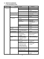
IV. SERVICE DIAGNOSIS
1. NO ICE PRODUCTION
PROBLEM
[1] The icemaker
will not start
POSSIBLE CAUSE
a) Power Supply
1. “OFF” position.
2. Loose connections.
3. Bad contacts.
4. Voltage too high.
b) Fuse (Inside Fused
Disconnect, if any)
c) Control Switch
d) Bin Control
Thermostat
e) High Pressure
Control
f) Transformer
g) Wiring to
Controller Board
h) Thermistor
i) Hot Gas Solenoid
Valve
j) Water Supply Line
k) Water Solenoid
1. Blown out.
1. “OFF” position.
2. Bad contacts.
1. Tripped with bin filled
with ice.
2. Ambient temperature
too cool.
3. Set too warm.
4. Bulb out of position.
5. Bad contacts or leaks in
bulb.
1. Bad contacts.
1. Thermal fuse blown out
or coil winding opened.
1. Loose connections or
open.
1. Leads short-circuit or
open and High
Temperature Safety
operates.
1. Continues to open in
freeze cycle and High
Temperature Safety
operates.
1. Water supply off and
water supply cycle does
not finish.
2. Condenser water
pressure too low or off
and Pressure Control
opens and closes frequently to finally operate
High Temperature Safety.
1. Mesh filter or orifice gets
clogged and water supply
cycle does not finish.
2. Coil winding opened.
3. Wiring to Water Valve.
49
REMEDY
1. Move to “ON” position.
2. Tighten.
3. Check for continuity and
replace.
4. Check and get
recommended voltage.
1. Check for short circuit
and replace.
1. Move to “ICE” position.
2. Check for continuity and
replace.
1. Remove ice.
2. Increase ambient
temperature.
3. See “II.2.[d]
CONTROLS AND
ADJUSTMENTS, 5) Bin
Control.”
4. Place in position.
5. Check for continuity and
replace.
1. Check for continuity and
replace.
1. Replace.
1. Check for continuity and
replace.
1. See “II.2.[d] CONTROLS
AND ADJUSTMENTS, 1)
Defrost Control.”
1. Check for power off in
freeze cycle and replace.
1. Check and get
recommended
pressure.
2. Check and get
recommended
pressure.
1. Clean.
2. Replace.
3. Check for loose
connection or open, and
replace.
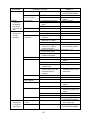
PROBLEM
POSSIBLE CAUSE
l) Controller Board
m) Interlock Switch
(Cleaning Valve)
[2] Water
continues to
be supplied,
and the icemaker will not
start.
[3] Compressor
will not start
or stops
operating
a) Float switch
b) Controller Board
a) Wash Switch
b) High Pressure
Controller
c) Water Regulator
d) Overload Protector
e) Starter
f) Start Capacitor or
Run Capacitor
g) Magnetic Contactor
[4] Water
continues to
be supplied in
freeze cycle.
1. Defective.
1. “OFF” position.
2. Bad contacts.
1. Connector disconnected.
2. Leads opened or defective
switch.
3. Float does not move freely.
1. Defective.
1. “WASH” position.
2. Bad contacts.
1. Dirty Air Filter or
Condenser.
2. Ambient or condenser
water temp. too warm.
3. Refrigerant overcharged.
4. Condenser water pressure
too low or off. [Watercooled model only].
5. Fan not operating. [Except
water-cooled model].
6. Refrigerant line or
components plugged.
1. Set too high.
1. Bad contacts.
2. Voltage too low.
3. Refrigerant overcharged or
undercharged.
4. Line Valve continues to
close in freeze cycle and
Overload Protector
operates.
1. Bad contacts.
2. Coil winding opened.
1. Defective.
1. Bad contacts.
h) Compressor
2. Coil winding opened.
1. Wiring to Compressor.
i) Controller board
2. Defective.
3. Protector tripped.
1. Defective.
a) Water Solenoid
Valve
b) Controller Board
1. Diaphragm does not close.
1. Defective.
50
REMEDY
1. See “II.2[e] CHECKING
CONTROLLER BOARD.”
1. Move to “ON” position.
2. Check for continuity and
replace.
1. Place in position.
2. Check and replace.
3. Clean or replace.
1. Replace.
1. Move to “ICE” position.
2. Check and replace.
1. Clean.
2. Reduce ambient temp.
3. Recharge.
4. Check and get
recommended pressure.
5. See chart 1 - [6].
6. Clean and replace Drier.
1. Adjust lower.
1. Check for continuity and
replace.
2. Increase voltage.
3. Recharge.
4. Check Line Valve's
operation in freeze cycle
and replace.
1. Check and replace.
2. Replace.
1. Replace.
1. Check for continuity and
replace.
2. Replace.
1. Check for loose
connection or open, and
replace.
2. Replace.
3. Reduce temperature.
1. See “II.2. [e] CHECKING
CONTROLLER BOARD.”
1. Check for water leaks
with icemaker off.
1. See “II.2.[e] CHECKING
CONTROLLER BOARD.”
PROBLEM
POSSIBLE CAUSE
[5] No water
a) Water Supply Line
comes from
Spray Tubes.
Water Pump
b) Water Solenoid
will not start, or
Valve
freeze cycle
time is too
c) Water System
short.
d) Pump Motor
e) Controller Board
[6] Fan Motor will a) Fan Motor
not start, or is
not operating.
b) Controller Board
[7] All components a) Refrigerant
run but no ice
is produced.
b) Compressor
c) Hot Gas Solenoid
Valve
d) Line Valve
e) Water Solenoid
Valve
f) Water Supply Line
[Water-cooled model
only]
REMEDY
1. Water pressure too low and 1. Check and get
water level in Water Tank
recommended pressure.
too low.
1. Dirty mesh filter or orifice
1. Clean.
and water level in Water
Tank too low.
1. Water leaks.
1. Check connections for
water leaks, and replace.
2. Clogged.
2. Clean.
3. Pump Out Check Valve
3. Check assembly and
leaking by.
clean.
1. Motor winding opened.
1. Replace.
2. Bearing worn out.
2. Replace.
3. Wiring to Pump Motor.
3. Check for loose
connection or open, and
replace.
4. Defective Capacitor.
4. Replace.
5. Defective or bound impeller. 5. Replace and clean.
6. Mechanical Seal worn out. 6. Check and replace.
1. Defective.
1. See “II.2. [e] CHECKING
CONTROLLER BOARD.”
1. Motor winding opened.
1. Replace.
2. Bearing worn out.
2. Replace.
3. Wiring to Fan Motor.
3. Check for loose
connection or open, and
replace.
4. Defective Capacitor.
4. Replace.
5. Fan blade bound.
5. Check and replace.
1. Defective.
1. See “II.2. [e] CHECKING
CONTROLLER BOARD.”
1. Undercharged.
1. Check for leaks and
recharge.
2. Air or moisture trapped.
2. Replace Drier, and
recharge.
1. Defective valve.
1. Replace.
1. Continues to open in freeze 1. Check and replace.
cycle.
1. Continues to close in
1. Check and replace
freeze cycle.
1. Water Solenoid Valve is
1. Check for water leaks
open during freeze.
with icemaker off.
1. Condenser water pressure 1. Check and get
too low or off and Pressure
recommended pressure.
Control opens and closes
frequently.
51
2. EVAPORATOR IS FROZEN UP
PROBLEM
[1] Freeze cycle
time is too
long.
POSSIBLE CAUSE
a) Float Switch
a) Evaporator
b) Water Supply Line
1. Scaled up.
1. Water pressure too low.
c) Water Filter System
d) Water Solenoid
Valve
e) Ambient and/or
water temperature
f) Line Valve
1. Dirty/Restricted.
1. Dirty mesh filter or orifice.
1. Too cool.
1. Increase temperature.
1. Continues to open in
harvest cycle.
1. Out of position or loose
attachment.
1. Check operation in
harvest cycle and replace.
1. See “V. 11. REMOVAL
AND REPLACEMENT OF
THERMISTOR.”
1. Adjust longer, referring
to “II. 2. [d] CONTROLS
AND ADJUSTMENT, 2)
Defrost Timer.”
2. See “II. 2.[e] CHECKING
CONTROLLER BOARD.”
1. Clean.
2. Place in position.
1. Clean.
1. Check for leaks and
recharge.
1. Place in position.
g) Thermistor
h) Controller Board
1. Defective.
1. Defrost Timer is set too
short.
2. Defective.
[3] Others
REMEDY
1. Check and replace.
2. Clean or replace.
1. Check for water leaks
with icemaker off.
1. See “II.2[e] CHECKING
CONTROLLER BOARD.”
1. Clean.
1. Check and get
recommended pressure.
1. Replace filter.
1. Clean.
b) Water Solenoid
Valve
c) Controller Board
[2] All ice formed
on Evaporator
does not fall
into bin in
harvest cycle.
1. Leads short-circuit or
defective switch.
2. Float does not move freely.
1. Diaphragm does not close.
a) Spray Tubes
b) Water System
c) Refrigerant
d) Expansion Valve
e) Hot Gas Solenoid
Valve
f) Water Supply Line
g) Water filter
1. Clogged.
2. Out of position.
1. Dirty.
1. Undercharged.
1. Bulb out of position or
loose attachment.
2. Defective.
1. Coil winding opened.
2. Plunger does not move.
3. Wiring to Hot Gas Valve.
2. Replace.
1. Replace.
2. Replace.
3. Check for loose
connection or open, and
replace.
1. Too small; requires 1/2" OD 1. Increase water line size.
line dedicated per machine.
1. Flow rate too small.
1. Replace with filter that
has larger flow rate.
52
3. LOW ICE PRODUCTION
PROBLEM
[1] Freeze cycle
time is long.
[2] Harvest cycle
time is long
POSSIBLE CAUSE
REMEDY
a) See chart 1 - [3], and check dirty Air Filter or Condenser, ambient or water
temperature, water pressure, Water Regulator or refrigerant charge.
b) See chart 2 - [1], and check Float Switch, Water Solenoid Valve or Controller
Board.
a) See chart 2 - [2], and check Controller Board, Thermistor, Evaporator, ambient
and/or water temperature, water supply line, Water Solenoid Valve, Line Valve,
or Hot Gas Valve.
4. ABNORMAL ICE
PROBLEM
[1] Small Cube
POSSIBLE CAUSE
REMEDY
a) Ice Cube Guide
1. Out of position.
1. Place in position.
Circulated water falls into
bin.
b) See chart 1 - [5], and check water supply line, Water Solenoid Valve, water system,
Pump Motor or Controller Board.
c) Pump Out Check Valve 1. Dirty.
1. Clean.
[2] Cloudy or
a) See chart 2 - [1] and - [3], and check Float Switch, Water Solenoid Valve,
irregular cube
Controller Board, Spray Tubes, water system, refrigerant charge or Expansion
Valve.
b) Spray Guide
1. Dirty.
1. Clean.
c) Water Quality
1. High hardness or contains 1. Install a water filter or
impurities.
softener.
5. OTHERS
PROBLEM
POSSIBLE CAUSE
[1] Icemaker will a) Bin Control
not stop when
Thermostat
bin is filled
with ice.
[2] Abnormal
a) Pump Motor
noise
b) Fan Motor
c) Compressor
d) Refrigerant Lines
[3] Ice in storage
bin often
melts.
a) Bin Drain
b) Icemaker and Bin
REMEDY
1. Set too cold.
2. Defective.
1. Adjust warmer.
2. Replace.
1. Bearings worn out.
1. Bearings worn out.
2. Fan blade deformed.
3. Fan blade does not move
freely.
1. Bearings worn out, or
cylinder valve broken.
2. Mounting pad out of
position.
1. Rub or touch lines or other
surfaces.
1. Plugged.
1. Drains not run separately.
1. Replace.
1. Replace.
2. Replace fan blade.
3. Replace.
53
1. Replace.
2. Reinstall
1. Replace.
1. Clean.
1. Separate the Drain Lines.
V.
REMOVAL AND REPLACEMENT OF COMPONENTS
IMPORTANT
Ensure all components, fasteners and thumbscrews are securely in place after
the equipment is serviced.
IMPORTANT
1. The Polyol Ester (POE) oils used in R-404A units can absorb moisture
quickly. Therefore it is important to prevent moisture from entering the system when replacing or servicing parts.
2. Always install a new filter drier every time the sealed refrigeration system is
opened.
3. Do not leave the system open for longer than 5 minutes when
replacing or servicing parts.
1. SERVICE FOR REFRIGERANT LINES
[a] REFRIGERANT RECOVERY
The icemaker unit is provided with two Refrigerant Access Valves–one on the low-side and
one on the high-side line. Using proper refrigerant practices recover the refrigerant from the
Access Valves and store it in an approved container. Do not discharge the refrigerant into
the atmosphere.
[b] EVACUATION AND RECHARGE [R-404A]
1) Attach Charging Hoses, a Service Manifold and a Vacuum Pump to the system. Be
sure to connect charging hoses to both High and Low -side Access Valves.
IMPORTANT
The vacuum level and Vacuum Pump may be the same as those for
current refrigerants. However, the rubber hose and gauge manifold to be used
for evacuation and refrigerant charge should be exclusively for POE oils.
2) Turn on the Vacuum Pump. Never allow the oil in the Vacuum Pump to flow
backward.
3) Allow the Vacuum Pump to pull down to a 29.9" Hg vacuum. Evacuating period depends
on pump capacity.
4) Close the Low-side Valve and High-side Valve on the Service Manifold.
54
5) Disconnect the Vacuum Pump, and attach a Refrigerant Service Cylinder to the
High-side line. Remember to loosen the connection, and purge the air from the
Hose. For water-cooled models, see the Nameplate for the required refrigerant
charge. For remote air-cooled models, see the Charge Label in the machine
compartment. Hoshizaki recommends only virgin refrigerant or reclaimed refrigerant
which meets ARI Standard No. 700-88 be used.
6) A liquid charge is recommended for charging an R-404A system. Invert the service
cylinder. Open the High-side, Service Manifold Valve.
7) Allow the system to charge with liquid until the pressures balance.
8) If necessary, add any remaining charge to the system through the Low-side. Use a
throttling valve or liquid dispensing device to add the remaining liquid charge
through the Low-side access port with the unit running.
9) Close the two Refrigerant Access Valves, and disconnect the Hoses and Service
Manifold.
10) Cap the Access Valves to prevent a possible leak.
2. BRAZING
DANGER
1. Refrigerant R-404A itself is not flammable at atmospheric pressure and
temperatures up to 176° F.
2. Refrigerant R-404A itself is not explosive or poisonous. However, when
exposed to high temperatures (open flames) R-404A can be decomposed to form hydrofluoric acid and carbonyl fluoride both of which are
hazardous.
3. Always recover the refrigerant and store it in an approved container. Do
not discharge the refrigerant into the atmosphere.
4. Do not use silver alloy or copper alloy containing Arsenic.
5. Do not use R-404A as a mixture with pressurized air for leak testing.
Refrigerant leaks can be detected by charging the unit with a little refrigerant, raising the pressure with nitrogen and using an electronic leak
detector.
Note: All brazing-connections inside the Evaporator Case are clear-paint coated.
Sandpaper the brazing connections before unbrazing the components. Use a
good abrasive cloth to remove coating.
55
3. REMOVAL AND REPLACEMENT OF COMPRESSOR
IMPORTANT
Always install a new Drier every time the sealed refrigeration system is
opened. Do not replace the Drier until after all other repair or replacement
has been made.
Note: When replacing a Compressor with a defective winding, be sure to install the new
Start Capacitor and Start Relay supplied with the replacement Compressor. Due
to the ability of the POE oil in the compressor to absorb moisture quickly, the
Compressor must not be opened more than 15 minutes for replacement or
service, . Do not mix lubricants of different compressors even if both are charged
with R-404A, except when they use the same lubricant.
1) Turn off the power supply.
2) Remove the panels.
3) Recover the refrigerant and store it in an approved container.
4) Remove the Terminal Cover on the Compressor, and disconnect the Compressor
Wiring.
5) Remove the Discharge and Suction Pipes using brazing equipment.
6) Remove the Hold-down Bolts, Washers and Rubber Grommets.
7) Slide and remove the Compressor. Unpack the new Compressor package. Install
the new Compressor.
8) Attach the Rubber Grommets of the prior Compressor.
9) Sandpaper the Suction, Discharge and Process Pipes.
10) Place the Compressor in position, and secure it using the Bolts and Washers.
11) Remove plugs from the Suction, Discharge and Process Pipes.
12) Braze the Process, Suction and Discharge lines (Do not change this order), while
purging with nitrogen gas flowing at the pressure 3-4 PSIG.
13) Install the new Filter Drier.
14) Check for leaks using nitrogen gas (140 PSIG) and soap bubbles.
56
15) Evacuate the system, and charge it with refrigerant. See the Nameplate for the
required refrigerant charge.
16) Connect the Terminals, and replace the Terminal Cover in its correct position.
17) Replace the panels in their correct positions.
18) Turn on the power supply.
4. REMOVAL AND REPLACEMENT OF DRIER
IMPORTANT
Always install a new Drier every time the sealed refrigeration system is
opened. Do not replace the Drier until after all other repair or replacement
has been made.
1) Turn off the power supply.
2) Remove the panels.
3) Recover the refrigerant and store it in an approved container.
4) Remove the Drier.
5) Install the new Drier, with the arrow on the Drier, in the direction of the refrigerant flow.
Use nitrogen gas at the pressure of 3 - 4 PSIG when brazing the tubings.
6) Check for leaks using nitrogen gas (140 PSIG) and soap bubbles.
7) Evacuate the system, and charge it with refrigerant. For water-cooled models, see the
Nameplate for the required refrigerant charge. For remote air-cooled models, see the
Charge Label in the machine compartment.
8) Replace the panels in their correct positions.
9) Turn on the power supply.
57
5. REMOVAL AND REPLACEMENT OF EXPANSION VALVE
IMPORTANT
Sometimes moisture in the refrigerant circuit exceeds the Drier capacity
and freezes up at the Expansion Valve. Always install a new Drier every
time the sealed refrigeration system is opened. Do not replace the Drier
until after all other repair or replacement has been made.
1) Turn off the power supply.
2) Remove the panels.
3) Recover the refrigerant and store it in an approved container.
4) Remove the insulation and the Expansion Valve Bulb on the suction line.
5) Remove the Expansion Valve Cover, and disconnect the Expansion Valve using
brazing equipment.
6) Braze the new Expansion Valve, with nitrogen gas flowing at the pressure of
3-4 PSIG.
WARNING
1. Do not heat the wall. Place a steel barrier for protection.
2. Always protect the valve body by using a damp cloth to prevent the
valve from overheating. Do not braze with the valve body exceeding
250°F.
7) Install the new Drier.
8) Check for leaks using nitrogen gas (140 PSIG) and soap bubbles.
9) Evacuate the system, and charge it with refrigerant. For water-cooled models, see
the Nameplate for the required refrigerant charge. For remote air-cooled models,
see the Charge Label in the machine compartment.
10) Attach the Bulb to the suction line in position. Be sure to secure it with clamps and
to insulate it.
11) Place the new set of Expansion Valve Covers in position.
12) Replace the panels in their correct position.
13) Turn on the power supply.
58
6. REMOVAL AND REPLACEMENT OF HOT GAS VALVE, LINE VALVE
AND GAS VALVE
CAUTION
Always use a copper tube of the same diameter and length when replacing
the hot gas lines; otherwise the performance may be reduced.
IMPORTANT
Always install a new Drier every time the sealed refrigeration system is
opened. Do not replace the Drier until after all other repair or replacement
has been made.
1) Turn off the power supply.
2) Remove the panels.
3) Recover the refrigerant and store it in an approved container.
4) Remove the screw and the Solenoid.
5) Disconnect the Hot Gas Valve, Line Valve or Gas Valve using brazing equipment.
6) Install the new valve.
WARNING
Always protect the valve body by using a damp cloth to prevent the valve
from overheating. Do not braze with the valve body exceeding 250°F.
7) Install the new Drier.
8) Check for leaks using nitrogen gas (140 PSIG) and soap bubbles.
9) Evacuate the system, and charge it with refrigerant. For air-cooled and watercooled models, see the Nameplate for the required refrigerant charge. For remote
air-cooled models, see the Charge Label in the machine compartment.
10) Cut the leads of the Solenoid allowing enough lead length to reconnect using
closed end connectors.
59
11) Connect the new Solenoid leads.
12) Attach the Solenoid to the valve body, and secure it with a screw.
13) Replace the panels in their correct positions.
14) Turn on the power supply.
7. REMOVAL AND REPLACEMENT OF EVAPORATOR
IMPORTANT
Always install a new Drier every time the sealed refrigeration system is
opened. Do not replace the Drier until after all other repairs or replacement
have been made.
1) Turn off the power supply.
2) Remove the panels and the Top Insulation over the Evaporator.
3) Recover the refrigerant and store it in an approved container.
4) Remove the Spray Tubes and the Insulations at the “U” shaped notch where the
refrigeration tubings go through the molded chassis.
5) Remove the Insulation Tube, and disconnect the Evaporator Inlet Tubing at the Tee
next to the Expansion Valve.
6) Lift up the Evaporator, and disconnect the Evaporator Outlet Tubing.
7) Install the new Evaporator.
8) Install the new Drier.
9) Check for leaks using nitrogen gas (140 PSIG) and soap bubbles.
10) Evacuate the system, and charge it with refrigerant. For water-cooled models, see
the Nameplate for the required refrigerant charge. For remote air-cooled models,
see the Charge Label in the machine compartment.
11) Replace the removed parts in the reverse order of which they were removed.
12) Replace the Top Insulation and the panels in their correct positions.
13) Turn on the power supply.
60
8. REMOVAL AND REPLACEMENT OF WATER REGULATING VALVE WATER-COOLED MODEL ONLY
IMPORTANT
Always install a new Drier every time the sealed refrigeration system is
opened. Do not replace the Drier until after all other repair or replacement
has been made.
1) Turn off the power supply.
2) Close the Water Supply Line Shut-off Valve.
3) Remove the panels.
4) Recover the refrigerant and store it in an approved container.
5) Disconnect the Capillary Tube at the Condenser outlet using brazing equipment.
6) Disconnect the Flare-connections of the valve.
7) Remove the screws and the valve from the Bracket.
8) Install the new valve, and braze the Capillary Tube.
9) Install the new Drier.
10) Check for leaks using nitrogen gas (140 PSIG) and soap bubbles.
11) Evacuate the system, and charge it with refrigerant. See the Nameplate for the
required refrigerant charge.
12) Connect the Flare-connections.
13) Open the Water Supply Line Shut-off Valve.
14) Check for water leaks.
15) Replace the panels in their correct positions.
16) Turn on the power supply.
61
9. ADJUSTMENT OF WATER REGULATING VALVE - WATER-COOLED
MODEL ONLY
The Water Regulating Valve (also called “WATER REGULATOR”) is factory-adjusted.
No adjustment is required under normal use. Adjust the Water Regulator, if necessary,
using the following procedures.
1) Attach a pressure gauge to the high-side line of the system. Or prepare a
thermometer to check for the condenser drain temperature.
2) Rotate the adjustment screw by using a flat blade screwdriver, so that the pressure
gauge shows 280 PSIG or the thermometer reads 108–117° F, 5 minutes after a
freeze cycle or icemaking process starts. When the pressure exceeds 280 PSIG, or
the condenser drain temperature exceeds 115° F, rotate the adjustment screw
counterclockwise. See Fig. 1 and the chart below.
3) Check that the pressure or the condenser drain temperature holds a stable setting.
Fig. 1
PSIG
WATER TEMP.
°F
PSIG
50
°F
PSIG
70
°F
90
AIR TEMP.
70
275
108
278
108
288
111
90
278
108
285
109
297
113
100
282
110
288
110
308
117
62
10. REMOVAL AND REPLACEMENT OF CONDENSING PRESSURE
REGULATOR (C.P.R.) - REMOTE AIR-COOLED MODEL ONLY
IMPORTANT
Always install a new Drier every time the sealed refrigeration system is
opened. Do not replace the Drier until after all other repair or replacement
has been made.
1) Turn off the power supply.
2) Remove the panels from the remote condenser unit.
3) Recover the refrigerant and store it in an approved container.
4) Before heating, break off the stub on the dome to release the dome charge.
5) Disconnect the C.P.R. using brazing equipment.
6) Install the new C.P.R. Use nitrogen gas at the pressure of 3-4 PSIG when brazing the
C.P.R.
WARNING
Always protect the C.P.R. body by using a damp cloth to prevent the C.P.R.
from overheating. Do not braze with the C.P.R. body exceeding 250°F.
7) Install the new Drier in the icemaker.
8) Check for leaks using nitrogen gas (140 PSIG) and soap bubbles.
9) Evacuate the system and charge it with refrigerant. See the Charge Label in the
machine compartment in the icemaker.
10) Replace the panels in their correct positions.
11) Turn on the power supply.
63
11. REMOVAL AND REPLACEMENT OF THERMISTOR
CAUTION
1. Fragile, handle very carefully.
2. Always use a recommended sealant (High Thermal Conductive Type),
Model KE4560RTV manufactured by SHINETSU SILICONE, Part Code
60Y000-11, or Part Code 4A0683-01 equivalent.
3. Always use a recommended foam insulation (Non-absorbent Type) or
equivalent.
1) Turn off the power supply.
Thermistor Lead
2) Remove the panels.
Cable Tie
3) Remove the Control Box Cover.
4) Disconnect the Thermistor leads from
the K3 Connector on the Controller Board.
5) Remove the Plastic Cable Ties, Foam
Insulation, Thermistor Holder and
Thermistor. See Fig. 2.
Foam Insulation
Thermistor Holder
Fig. 2
6) Scrape away the old sealant on the
Thermistor Holder and the Suction Pipe.
7) Wipe off moisture or condensation on the Suction Pipe.
8) Smoothly apply recommended sealant (KE4560RTV, Part Code 60Y000-11 or
4A0683-01) to the Thermistor Holder concave.
9) Attach the new Thermistor to the Suction Pipe very carefully to prevent damage to
the leads. And secure it using the Thermistor Holder and recommended foam
insulation.
64
10) Secure the insulation using the Plastic Cable Ties.
11) Connect the Thermistor leads through the bushing of the Control Box to the K3
Connector on the Controller Board.
Note: Do not cut the leads of the Thermistor while installing it.
12) Replace the Control Box Cover and the panels in their correct positions.
13) Turn on the power supply.
12. REMOVAL AND REPLACEMENT OF FAN MOTOR
Note: When replacing a Fan Motor with defective winding, it is recommended that a new
capacitor be installed.
1) Turn off the power supply.
2) Remove the panels.
3) Remove the Junction Box Cover from the remote condenser unit (Remote Air-cooled
model).
4) Remove the closed end connectors from the Fan Motor leads.
5) Remove the Fan Motor Bracket and Fan Motor.
6) Install the new Fan Motor, and replace the removed parts in the reverse order of
which they were removed.
7) Replace the panels in their correct positions.
8) Replace the Junction Box Cover in its correct position (Remote Air-cooled model).
9) Turn on the power supply.
65
13. REMOVAL AND REPLACEMENT OF WATER VALVE
1) Turn off the power supply.
2) Close the Water Supply Line Shut-off Valve.
3) Remove the Front Panel.
4) Remove the Valve Outlet Tubing by releasing the Clamp.
5) Remove the Bracket from the unit.
6) Remove the Fitting Nut and Water Valve.
7) Disconnect the Terminals from the Water Valve.
8) Install the new Water Valve, and replace the removed parts in the reverse order of
which they were removed.
9) Open the Water Supply Line Shut-off Valve.
10) Turn on the power supply.
11) Check for leaks.
12) Replace the Front Panel in its correct position.
14. REMOVAL AND REPLACEMENT OF PUMP MOTOR
1) Turn off the power supply.
2) Remove the Front Panel.
3) Drain the Water Tank by removing the Insulation Panel
and the cap at the front of the ice dropping hole.
See Fig. 3.
4) Replace the removed parts in their correct positions.
5) Disconnect the Pump Suction and Discharge Hoses.
6) Remove the screws and the Pump Motor Bracket.
Fig. 3
66
7) Remove the closed end connectors from the Pump Motor leads.
8) Remove the two screws and the Pump Motor Bracket.
9) Remove the Pump Housing, and check the Impeller.
10) If the Impeller is defective, install a new Impeller.
11) Install the new motor or new parts, and replace the removed parts in the reverse
order of which they were removed.
12) Turn on the power supply, and check for leaks.
13) Replace the Front Panel in its correct position.
15. REMOVAL AND REPLACEMENT OF SPRAY TUBES
1) Turn off the power supply.
2) Remove the Front Panel and the Insulation Panel.
3) Remove the Rubber Hoses from the Spray Tubes (Water Supply Pipe).
4) Release the Clamps, and disconnect the Rubber Hoses.
5) Remove the Spray Tubes by squeezing the side tabs.
6) Install the new Spray Tubes, and replace the removed parts in the reverse order of
which they were removed.
7) Replace the panels in their correct positions.
8) Turn on the power supply.
67
VI.
MAINTENANCE AND CLEANING INSTRUCTIONS
IMPORTANT
Ensure all components, fasteners and thumbscrews are securely in place
after any maintenance or cleaning is done to the equipment.
1. PREPARING THE ICEMAKER FOR LONG STORAGE
WARNING
When shutting off the icemaker for an extended time, drain out all water from
the water tank and remove the ice from the Storage Bin. The Storage Bin
should be cleaned and dried. Drain the icemaker to prevent damage to the
water supply line at sub-freezing temperatures, using air or carbon dioxide.
Shut off the icemaker until the proper ambient temperature is resumed.
• When the icemaker is not used for two or three days, it is sufficient to only move the
Control Switch to the “OFF” position, unless the icemaker will be at sub-freezing
temperatures.
[1] On water-cooled model only, first remove the water from the water-cooled condenser:
1) Remove the Front Panel.
2) Move the Control Switch, on the Control Box, to the “OFF” position.
3) Wait 3 minutes.
4) Move the Control Switch to the “ICE” position.
5) Allow 5 minutes for the icemaker to fill with water and the Water Pump to start
operating.
6) Close the Water-cooled Condenser Water Supply Line Shut-off Valve.
7) Open the Drain Valve for the water-cooled condenser water supply line.
8) Allow the line to drain by gravity.
9) Attach compressed air or carbon dioxide supply to the Condenser Water Line Drain
Valve.
10) Quickly blow the water-cooled condenser out using compressed air or carbon dioxide
until water stops coming out.
68
[2] Remove the water from the potable water supply line:
1) Remove the Front Panel. (Except water-cooled model)
2) Move the Control Switch, on the Control Box, to the “OFF” position.
3) Wait 3 minutes.
4) Close the Potable Water Supply Line Shut-off Valve and open the Potable Water
Supply Line Drain Valve.
5) Allow the line to drain by gravity.
6) Attach compressed air or carbon dioxide supply to the Potable Water Line Drain Valve.
7) Move the Control Switch to the “ICE” position.
8) Blow the potable water line out using compressed air or carbon dioxide.
[3] Drain the Potable Water Tank:
1) Turn off the power supply.
2) Move the Control Switch to the “OFF”
position.
3) Drain the Water Tank by removing the
Insulation Panel and the Cap located
on the front bottom part of the Ice
Dropping Hole. See Fig. 4.
4) Replace the removed parts in their
correct positions.
5) Remove all ice from the Storage Bin,
and clean the Storage Bin.
6) Replace the Front Panel in its correct
position.
Fig. 4
7) Close the Drain Valve.
69
2. CLEANING PROCEDURE
IMPORTANT
Ensure all components, fasteners and thumbscrews are securely in place
after any maintenance or cleaning is done to the equipment.
WARNING
1. HOSHIZAKI recommends cleaning this unit at least once a year. More
frequent cleaning, however, may be required in some existing water
conditions.
2. To prevent injury to individuals and damage to the icemaker, do not use
ammonia type cleaners.
3. Always wear liquid-proof gloves for safe handling of the cleaning and
sanitizing solution. This will prevent irritation in case the solution comes
into contact with skin.
IMPORTANT
1. The Cleaning Valve is used to allow solution flow to the inside of the
Evaporator during the cleaning and sanitizing operation. It should be
closed for all icemaking operation. The Compressor will not operate
unless this valve is completely closed.
2. To open the Cleaning Valve, the Valve Handle should be parallel to the
valve body. To close the valve, the Valve Handle should be at a right
angle to the valve body.
70
[a] CLEANING PROCEDURE
1) Dilute 27 fl. oz. of the recommended cleaner Hoshizaki “Scale Away” or
“LIME-A-WAY” (Economics Laboratory, Inc.) with 5 gal. of water.
2) Remove all ice from the Evaporator and the Storage Bin.
Note: To remove cubes on the Evaporator, turn off the power supply and turn
it on after 3 minutes. The defrost cycle starts and the cubes will be
removed from the Evaporator.
3) Turn off the power supply.
4) Remove the Front Panel and then remove the Insulation Panel, by first removing
the thumbscrew, lifting the panel slightly and pulling it toward you.
5) Drain the Water Tank by removing the Cap located on the front bottom part of
the Ice Dropping Hole. See Fig. 4.
6) After tank has drained, replace the removed parts in their correct positions.
7) Pour the cleaning solution into the Water Tank.
8) Fully open the Cleaning Valve on the left side wall of the machine compartment.
9) Move the Control Switch, on the Control Box, to the “WASH” position.
10) Replace the Insulation Panel and the Front Panel in their correct positions.
11) Turn on the power supply, and start the washing process.
12) Turn off the power supply after 30 minutes.
13) Remove the Front Panel and the Insulation Panel.
14) Drain the Water Tank. (See the above step 5).
15) Replace the tubing and the Insulation Panel in their correct positions.
16) Move the Control Switch to the “ICE” position.
17) Close the Cleaning Valve.
Note: The icemaker will not operate unless the Cleaning Valve is completely closed.
18) Replace the Front Panel in its correct position.
71
19) Turn on the power supply to fill the Water Tank with water.
20) Turn off the power supply after 3 minutes.
21) Remove the Front Panel, and fully open the Cleaning Valve.
22) Move the Control Switch to the “Wash” position.
23) Replace the Front Panel in its correct position.
24) Turn on the power supply to rinse off the cleaning solution.
25) Turn off the power supply after 5 minutes.
26) Remove the Front Panel and Insulation Panel.
27) Drain the Water Tank by removing the Cap located on the front bottom part of
the Ice Dropping Hole. See Fig. 4.
28) After the tank has drained, replace the removed parts in their correct positions.
Note: Do not replace the Insulation Panel when you proceed to
“[b] SANITIZING PROCEDURE.”
29) Repeat the above steps 16) through 28) three more times to rinse thoroughly.
Note: If you do not sanitize the icemaker, go to step 9) in “[b] SANITIZING
PROCEDURE.”
72
[b] SANITIZING PROCEDURE - Following Cleaning Procedure
1) Dilute a 5.25% Sodium Hypochlorite solution (chlorine bleach) with water (Add 2.5
fl. oz. of sanitizer to 5 gal. of water).
2) Remove the Insulation Panel, if it is in its normal position.
3) Pour the sanitizing solution into the Water Tank.
4) Replace the Insulation Panel and the Front Panel in their correct positions.
Note: Make sure that the Control Switch is in the “WASH” position and the
Cleaning Valve is in the “Open” position.
5) Turn on the power supply, and start the sanitizing process.
6) Turn off the power supply after 15 minutes.
7) Remove the Front Panel and if necessary, the Insulation Panel.
8) Drain the Water Tank. See the above step 5) in “[a] CLEANING PROCEDURE.”
9) Replace the removed parts and the Insulation Panel in their correct positions.
10) Repeat the above steps 16) through 28) in “[a] CLEANING PROCEDURE” two
times to rinse thoroughly.
11) Close the Cleaning Valve.
12) Move the Control Switch to the “ICE” position.
13) Replace the Front Panel in its correct position.
14) Clean the Storage Bin with water.
15) Turn on the power supply, and start the automatic icemaking process.
73
3. MAINTENANCE
IMPORTANT
This icemaker must be maintained individually, referring to the instruction
manual and labels provided with the icemaker.
1) Stainless Steel Exterior
To prevent corrosion, wipe the exterior occasionally with a clean and soft cloth. Use a
damp cloth containing a neutral cleaner to wipe off oil or dirt build up.
2) Storage Bin and Scoop
• Wash your hands before removing ice. Use the plastic scoop provided.
• The Storage Bin is for ice use only. Do not store anything else in the bin.
• Keep the scoop clean. Clean it by using a neutral cleaner and rinse thoroughly.
• Clean the bin liner by using a neutral cleaner. Rinse thoroughly after cleaning.
3) Condenser (Except water-cooled model)
Check the Condenser once a year, and clean if required by using a brush or vacuum
cleaner. More frequent cleaning may be required depending on the
location of the icemaker.
74