1
89/336
73/23
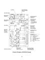
MODULAR CRESCENT CUBER
NUMBER:
73125
ISSUED: December 17, 2004
KM-280MAH-E
KM-500MAH-E
KM-630MAH-E
SERVICE MANUAL
FOR QUALIFIED SERVICE PERSON
HOSHIZAKI
IMPORTANT
Only qualified service technicians should attempt to service or maintain this
icemaker. No service or maintenance should be undertaken until the technician
has thoroughly read this Service Manual.
HOSHIZAKI provides this manual primarily to assist qualified service technicians in the
service and maintenance of the icemaker.
Should the reader have any questions or concerns which have not been satisfactorily
addressed, please call HOSHIZAKI CARE for assistance.
TEL: +44 (0) 1707322493
FAX: +44 (0) 1707322315
Hoshizaki Care Branch Offices:
Benelux
TEL: +31 (0) 206918499
FAX: +31 (0) 206918768
Germany
TEL: +49 (0) 215492810
FAX: +49 (0) 2154928128
France
TEL: +33 (0) 148137130
FAX: +33 (0) 148130992
Note:To expedite assistance, all correspondence/communication MUST include the
following information:
• Model Number
• Serial Number
• Complete and detailed explanation of the problem
2
Please review this manual. It should be read carefully before the icemaker is serviced or
maintenance operations performed. Only qualified service technicians should service and
maintain the icemaker. This manual should be made available to the technician prior to
service or maintenance.
CONTENTS
I. Specifications .................................................................................................................... 5
A. KM-280MAH-E (air-cooled) .......................................................................................... 5
B. KM-500MAH-E (air-cooled) .......................................................................................... 6
C. KM-630MAH-E (air-cooled) ......................................................................................... 7
II. General Information .......................................................................................................... 8
A. Dimensions .................................................................................................................. 8
1. KM-280MAH-E ....................................................................................................... 8
2. KM-500MAH-E ....................................................................................................... 9
3. KM-630MAH-E ..................................................................................................... 10
B. Construction ............................................................................................................... 11
1. KM-280MAH-E ..................................................................................................... 11
2. KM-500MAH-E ..................................................................................................... 12
3. KM-630MAH-E ..................................................................................................... 13
C. Controller Board......................................................................................................... 14
1. Solid-State Control ............................................................................................... 14
2. Controller Board ................................................................................................... 14
3. Sequence ............................................................................................................. 19
4. Controls and Adjustments .................................................................................... 22
5. Checking the Controller Board ............................................................................. 25
D. Mechanical Bin Control .............................................................................................. 26
1. Proximity Switch ................................................................................................... 26
2. Explanation of Operation ...................................................................................... 26
3. Troubleshooting (Mechanical Bin Control Only) .................................................... 27
III. Technical Information ..................................................................................................... 28
A. Water Circuit and Refrigerant Circuit .......................................................................... 28
1. KM-280MAH-E ..................................................................................................... 28
2. KM-500MAH-E, KM-630MAH-E ........................................................................... 29
B. Wiring Diagrams......................................................................................................... 30
1a. KM-280MAH-E (auxiliary codes L-0 through M-1) .............................................. 30
1b. KM-280MAH-E (auxiliary codes M-2 and later) ................................................... 31
2a. KM-500MAH-E (auxiliary codes L-0 through M-1) .............................................. 32
2b. KM-500MAH-E (auxiliary codes M-2 and later) ................................................... 33
3a. KM-630MAH-E (auxiliary codes L-0 through M-1) .............................................. 34
3b. KM-630MAH-E (auxiliary codes M-2 and later) ................................................... 35
C. Timing Chart .............................................................................................................. 36
D. Performance Data ...................................................................................................... 38
1. KM-280MAH-E ..................................................................................................... 38
2. KM-500MAH-E ..................................................................................................... 39
3. KM-630MAH-E ..................................................................................................... 40
3
IV. Service Diagnosis .......................................................................................................... 41
A. No Ice Production ...................................................................................................... 41
B. Evaporator is Frozen Up ............................................................................................ 45
C. Low Ice Production .................................................................................................... 46
D. Abnormal Ice .............................................................................................................. 46
E. Other .......................................................................................................................... 46
V. Removal and Replacement of Components ................................................................... 47
A. Service for Refrigerant Lines ...................................................................................... 47
1. Refrigerant Recovery ............................................................................................ 47
2. Evacuation and Recharge [R-404A] ..................................................................... 47
B. Brazing ....................................................................................................................... 49
C. Removal and Replacement of Compressor ............................................................... 49
D. Removal and Replacement of Drier ........................................................................... 50
E. Removal and Replacement of Expansion Valve ........................................................ 51
F. Removal and Replacement of Hot Gas Valve ............................................................. 52
G. Removal and Replacement of Evaporator ................................................................. 53
H. Removal and Replacement of Thermistor .................................................................. 54
I. Removal and Replacement of Fan Motor .................................................................... 55
J. Removal and Replacement of Water Valve ................................................................. 56
K. Removal and Replacement of Pump Motor................................................................ 56
L. Removal and Replacement of Float Switch................................................................ 57
M. Removal and Replacement of Spray Tubes ............................................................... 58
N. Removal and Replacement of Transformer ................................................................ 58
VI. Cleaning and Maintenance Instructions ....................................................................... 59
A. Preparing the Icemaker for Long Storage ................................................................... 59
B. Cleaning and Sanitizing Procedures ......................................................................... 60
1. Cleaning Procedure ............................................................................................. 60
2. Sanitizing Procedure - Following Cleaning Procedure ......................................... 62
C. Maintenance .............................................................................................................. 63
4
I. Specifications
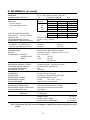
A. KM-280MAH-E (air-cooled)
AC SUPPLY VOLTAGE
AMPERAGE
MAXIMUM FUSE SIZE
APPROXIMATE ICE PRODUCTION
PER 24 HR.
lbs./day ( kg/day )
Reference without *marks
FOR THE EUROPEAN MARKET
ICE CAPACITY
SHAPE OF ICE
ICE PRODUCTION PER CYCLE
APPROXIMATE STORAGE CAPACITY
ELECTRIC & WATER CONSUMPTION
ELECTRIC W (kWH/100 lbs.)
WATER gal./24HR (gal./100 lbs.)
EXTERIOR DIMENSIONS (WxDxH)
EXTERIOR FINISH
WEIGHT
CONNECTIONS - ELECTRIC
- WATER SUPPLY
- DRAIN
CUBE CONTROL SYSTEM
HARVESTING CONTROL SYSTEM
ICE MAKING WATER CONTROL
COOLING WATER CONTROL
BIN CONTROL SYSTEM
COMPRESSOR
CONDENSER
EVAPORATOR
REFRIGERANT CONTROL
REFRIGERANT CHARGE
DESIGN PRESSURE
P.C. BOARD CIRCUIT PROTECTION
COMPRESSOR PROTECTION
REFRIGERANT CIRCUIT PROTECTION
LOW WATER PROTECTION
ACCESSORIES -SUPPLIED
-REQUIRED
OPERATING CONDITIONS
220-240/50/1
5.1 A ( 5 Min. Freeze AT 104°F / WT 80°F)
15 A
MINIMUM CIRCUIT AMPACITY 15A
Ambient
WATER TEMP. (°F)
Temp.(°F)
50
70
90
70
*258 (117)
231 (105)
204 (93)
80
237 (108)
196 (89)
175 (79)
90
231 (105)
*166 (75)
142 (164)
100
229 (104)
160 (73)
120 (54)
10/10°C
304 (138)
21/15°C
252 (114)
30/25°C
178 (81)
Crescent Cube
4.7 lbs. ( 2.16 kg ) 240 pcs.
N/A
90/70°F
70/50°F
802 (11.6)
763 (7.1)
59 (35.3)
99 (38.3)
22" x 27-3/8" x 30-5/16" (560 x 695 x 770 mm)
Stainless Steel, Galvanized Steel (Rear)
Net 151 lbs. ( 69 kg ), Shipping 175 lbs. (80 kg)
Cord - Connection
Inlet
1/2" FPT
Outlet
3/4" FPT
3/8" OD Pipe
Float Switch
Hot Gas and Water, Thermistor and Timer
Timer Controlled. Overflow Pipe
N/A
Thermostat
Hermetic,
Model AKA9438ZXC
Air-cooled, Fin and tube type
Vertical type, Stainless Steel and Copper
Thermostatic Expansion Valve
R-404A,
12 oz. ( 340 g )
High 467 PSIG, Low 230 PSIG
High Voltage Cut-out ( Internal )
Auto-reset Overload Protector ( Internal )
Auto-reset High Pressure Control Switch
Float Switch
N/A
Ice Storage Bin
VOLTAGE RANGE
198 - 254 V
AMBIENT TEMP.
45 -100° F
WATER SUPPLY TEMP.
45 - 90° F
WATER SUPPLY PRESSURE
10 - 113 PSIG
Note: We reserve the right to make changes in specifications and design without prior
notice.
5
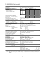
B. KM-500MAH-E (air-cooled)
AC SUPPLY VOLTAGE
AMPERAGE
MINIMUM CIRCUIT AMPACITY
APPROXIMATE ICE PRODUCTION
PER 24 HR.
lbs./day ( kg/day )
Reference without *marks
FOR THE EUROPEAN MARKET
ICE CAPACITY
lbs./day ( kg/day )
SHAPE OF ICE
ICE PRODUCTION PER CYCLE
APPROXIMATE STORAGE CAPACITY
ELECTRIC & WATER CONSUMPTION
ELECTRIC W (kWH/100 lbs.)
WATER gal./24HR (gal./100 lbs.)
EXTERIOR DIMENSIONS (WxDxH)
EXTERIOR FINISH
WEIGHT
CONNECTIONS - ELECTRIC
- WATER SUPPLY
- DRAIN
CUBE CONTROL SYSTEM
HARVESTING CONTROL SYSTEM
ICE MAKING WATER CONTROL
COOLING WATER CONTROL
BIN CONTROL SYSTEM
COMPRESSOR
CONDENSER
EVAPORATOR
REFRIGERANT CONTROL
REFRIGERANT CHARGE
DESIGN PRESSURE
P.C. BOARD CIRCUIT PROTECTION
COMPRESSOR PROTECTION
REFRIGERANT CIRCUIT PROTECTION
LOW WATER PROTECTION
ACCESSORIES -SUPPLIED
-REQUIRED
OPERATING CONDITIONS
220-240/50/1
5.5 A ( 5 Min. Freeze AT 104°F / WT 80°F)
15 A
MAXIMUM FUSE SIZE
15 A
Ambient
WATER TEMP. (°F)
Temp.(°F)
50
70
90
70
*480 (218)
446 (202)
403 (183)
80
454 (206)
402 (182)
360 (163)
90
446 (202)
*365 (166)
321 (146)
100
438 (199)
355 (161)
281 (127)
10/10 °C
540 (245)
21/15 °C
471 (214)
30/25 °C
355 (161)
Crescent Cube
9.5 lbs. ( 4.3 kg ) 480 pcs.
N/A
90/70°F
70/50°F
1019 (6.7)
940 (4.7)
149 (40.8)
242 (50.5)
22" x 27-3/8" x 30-5/16" (560 x 695 x 770 mm)
Stainless Steel, Galvanized Steel (Rear)
Net 146 lbs. ( 66 kg ), Shipping 170 lbs. ( 77 kg )
Cord - Connection
Inlet
1/2" FPT
Outlet
3/4" FPT
3/8" OD Pipe
Float Switch
Hot Gas and Water, Thermistor and Timer
Timer Controlled. Overflow Pipe
N/A
Thermostat
Hermetic,
Model AKA9455ZXC
Air-cooled, Fin and Tube type
Vertical type, Stainless Steel and Copper
Thermostatic Expansion Valve
R-404A,
1 lbs. 10 oz. ( 735 g )
High 467 PSIG, Low 230 PSIG
High Voltage Cut-out ( Internal )
Auto-reset Overload Protector ( Internal )
Auto-reset High Pressure Control Switch
Float Switch
N/A
Ice Storage Bin
VOLTAGE RANGE
198 - 254 V
AMBIENT TEMP.
45 -100° F
WATER SUPPLY TEMP.
45 - 90° F
WATER SUPPLY PRESSURE
10 - 113 PSIG
Note: We reserve the right to make changes in specifications and design without prior
notice.
6
C. KM-630MAH-E (air-cooled)
AC SUPPLY VOLTAGE
AMPERAGE
MINIMUM CIRCUIT AMPACITY
APPROXIMATE ICE PRODUCTION
PER 24 HR.
lbs./day ( kg/day )
Reference without *marks
FOR THE EUROPEAN MARKET
ICE CAPACITY
lbs./day ( kg/day )
SHAPE OF ICE
ICE PRODUCTION PER CYCLE
APPROXIMATE STORAGE CAPACITY
ELECTRIC & WATER CONSUMPTION
ELECTRIC W (kWH/100 lbs.)
WATER gal./24HR (gal./100 lbs.)
EXTERIOR DIMENSIONS (WxDxH)
EXTERIOR FINISH
WEIGHT
CONNECTIONS - ELECTRIC
- WATER SUPPLY
- DRAIN
CUBE CONTROL SYSTEM
HARVESTING CONTROL SYSTEM
ICE MAKING WATER CONTROL
COOLING WATER CONTROL
BIN CONTROL SYSTEM
COMPRESSOR
CONDENSER
EVAPORATOR
REFRIGERANT CONTROL
REFRIGERANT CHARGE
DESIGN PRESSURE
P.C. BOARD CIRCUIT PROTECTION
COMPRESSOR PROTECTION
REFRIGERANT CIRCUIT PROTECTION
LOW WATER PROTECTION
ACCESSORIES -SUPPLIED
-REQUIRED
OPERATING CONDITIONS
220-240/50/1
9 A ( 5 Min. Freeze AT 104°F / WT 80°F)
15 A
MAXIMUM FUSE SIZE
15 A
Ambient
WATER TEMP. (°F)
Temp.(°F)
50
70
90
70
*624 (283)
576 (261)
520 (236)
80
587 (266)
513 (233)
463 (210)
90
576 (261)
*460 (209)
406 (184)
100
568 (258)
447 (203)
357 (162)
10/10 °C
701 (318)
20/15 °C
611 (277)
30/25 °C
461 (209)
Crescent Cube
14.3 lbs. ( 6.5 kg ) 720 pcs.
N/A
90/70°F
70/50°F
1399 (7.3)
1300 (5.0)
153 (33.2)
208 (33.3)
22" x 27-3/8" x 37-7/16" (560 x 695 x 950 mm)
Stainless Steel, Galvanized Steel (Rear)
Net 165 lbs. ( 75 kg ), Shipping 185 lbs. ( 84 kg )
Permanent - Connection
Inlet
1/2" FPT
Outlet
3/4" FPT
3/8" OD Pipe
Float Switch
Hot Gas and Water, Thermistor and Timer
Timer Controlled. Overflow Pipe
N/A
Thermostat
Hermetic,
Model RS64C2E-IAZ-219
Air-cooled, Fin and Tube type
Vertical type, Stainless Steel and Copper
Thermostatic Expansion Valve
R-404A,
1 lbs. 6 oz. ( 635 g )
High 467 PSIG, Low 230 PSIG
High Voltage Cut-out ( Internal )
Auto-reset Overload Protector ( Internal )
Auto-reset High Pressure Control Switch
Float Switch
N/A
Ice Storage Bin
VOLTAGE RANGE
198 - 254 V
AMBIENT TEMP.
45 -100° F
WATER SUPPLY TEMP.
45 - 90° F
WATER SUPPLY PRESSURE
10 - 113 PSIG
Note: We reserve the right to make changes in specifications and design without prior
notice.
7
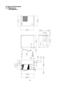
II. General Information
A. Dimensions
1. KM-280MAH-E
8
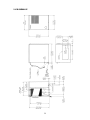
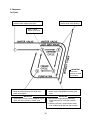
2. KM-500MAH-E
9
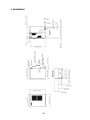
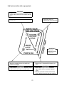
3. KM-630MAH-E
10
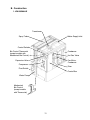
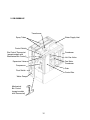
B. Construction
1. KM-280MAH-E
Transformer
Spray Tube
Water Supply Inlet
Control Switch
Bin Control Thermostat
(except models with
Mechanical Bin Control)
Condenser
Expansion Valve
Fan Motor,
Condenser
Hot Gas Valve
Compressor
Drier
Float Switch
Control Box
Water Pump
Mechanical
Bin Control
(except models
with Thermostat)
11
2. KM-500MAH-E
Transformer
Spray Tubes
Water Supply Inlet
Control Switch
Bin Control Thermostat
(except models with
Mechanical Bin Control)
Condenser
Expansion Valve
Fan Motor
Condenser
Hot Gas Valve
Compressor
Drier
Float Switch
Control Box
Water Pump
Mechanical
Bin Control
(except models
with Thermostat)
12
3. KM-630MAH-E
Transformer
Spray Tubes
Water Supply Inlet
Control Switch
Bin Control Thermostat
(except models with
Mechanical Bin Control)
Condenser
Expansion Valve
Fan Motor
Condenser
Hot Gas Valve
Compressor
Drier
Float Switch
Control Box
Water Pump
Mechanical
Bin Control
(except models
with Thermostat)
13
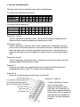
C. Controller Board
1. Solid-State Control
a) A HOSHIZAKI exclusive solid-state control is employed in Modular Crescent Cubers.
b) A printed circuit board (hereafter called “controller board”) includes a stable and high
quality control system.
c) All models are pretested and factory-adjusted.
2. Controller Board
CAUTION
1. Fragile, handle very carefully.
2. A controller board contains integrated circuits, which are susceptible to
failure due to static discharge. It is especially important to touch the metal
part of the unit when handling or replacing the board.
3. Do not touch the electronic devices on the board or the back of the board to
prevent damage to the board.
4. Do not change wiring and connections. Do not misconnect K3, K4 and K5,
because the same connector is used for the thermistor (white), float switch
(black), and mechanical bin control (red).
(For machines with thermostat, there is no connection on K4.)
5. Always replace the whole board assembly when it goes bad.
6. Do not short out power supply to test for voltage.
Part Number
2A1410-01
Controller Board
Type
HOS-001A (Control Products - 10 Pin)
Features of Control Products “E” Controller Board
a) Maximum Water Supply Period - 6 minutes
Water solenoid valve opening in the defrost (harvest) cycle is limited by the defrost timer.
The water valve cannot remain open longer than the maximum period. The water valve
can close in less than six minutes if the defrost cycle is completed.
b) Defrost Timer
The defrost cycle starts when the float switch opens and completes the freeze cycle. But
the defrost timer does not start counting until the thermistor senses 9°C at the evaporator
outlet. The period from the end of the freeze cycle up to the point of the thermistor's
sensing varies depending on the ambient and water temperatures.
14
c) High Temperature Safety — 53 ± 4°C
The temperature of the suction line in the refrigerant circuit is limited by the high
temperature safety. During the defrost cycle the evaporator temperature rises. The
thermistor senses 9°C and starts the defrost timer. After the defrost timer counts down to
zero, the normal freeze cycle begins. If the evaporator temperature continues to rise, the
thermistor will sense the rise in temperature and at 53 ±4°C the thermistor operates the
high temperature safety. This high temperature safety shuts down the circuit and the
icemaker automatically stops. This high temperature safety protects the unit from
excessive temperature. To reset the safety, turn the power off and back on again. This
high temperature safety protects the unit from excessive temperature. The control board
will beep every 3 seconds. The white reset button on the control board must be pressed
with power on to reset the safety.
d) Low Water Safety
If the pump motor is operated without water, the mechanical seal can fail. To prevent this
type of failure, the controller board checks the position of the float switch at the end of the
initial one minute water fill cycle and at the end of each defrost cycle.
If the float switch is in the up position (electrical circuit closed), the controller board
changes to the ice making cycle. If the float switch is in the down position (electrical
circuit open), the controller board changes to a one minute water fill cycle before starting
the ice making cycle. This method allows for a low water safety shut down to protect the
water pump from mechanical seal failure.
e) High Voltage Cut-out — control voltage > 147Vac ±5%
The maximum allowable supply voltage of this icemaker is limited by the high voltage
cut-out. If miswiring causes excessive voltage on the controller board, the high voltage
cut-out shuts down the circuit in 3 seconds and the icemaker automatically stops. When
the proper supply voltage is resumed, the icemaker automatically starts running again.
The control board will signal this problem using 7 beeps every 3 seconds.
f) LED Lights and Audible Alarm Safeties
The red LED indicates proper control voltage and will remain on unless a control voltage
problem occurs. At startup a 5 second delay occurs while the board conducts an internal
timer check. A short beep occurs when the power switch is turned ON or OFF.
15
The green LEDs 1-4 represent the corresponding relays and energize and sequence
5 seconds from initial startup as follows:
Sequence Step
1 Minute Fill Cycle
Harvest Cycle
Freeze Cycle
Reverse Pump Out
Time LEDs are Lit
Min.
Max.
Avg.
4
60 seconds
1, 4, and 2 2 minutes 20 minutes 3 to 5 minutes
1
5 minutes 60 minutes 30 to 35 minutes
1, 3, and 2 10 seconds 20 seconds factory setting
LED
{LED 1 – Comp; LED 2 - HGV/CFM; LED 3 – PM; LED 4 - WV}
The built in safeties shut down the unit and have alarms as follows:
No. of Beeps
Type of Alarm
(every 3 sec.)
1
High Evaporator Temp.
(temperature > 53°C)
2
Defrost Backup Timer
(defrost > 20 min.)
3
Freeze Backup Timer
(freeze > 60 min.)
4
Short Circuit
(machines with
mechanical bin control
ONLY)
Open Circuit
(machines with
mechanical bin control
ONLY)
5
Notes
Check for defrost problem (stuck HGV or
relay), hot water entering unit, stuck
headmaster, or shorted thermistor.
Orange LED marked 20 MIN lights up.
Check for open thermistor, HGV not
opening, TXV leaking by, low charge, or
inefficient compressor.
Yellow LED marked 60 MIN lights up.
Check for F/S stuck closed (up), WV
leaking by, HGV leaking by, TXV not
feeding properly, low charge, or
inefficient compressor.
Short circuit between the K4 connection
on the control board and the bin control
relay. Check connections and replace
wire harness if necessary.
Open circuit between the K4 connection
on the control board and the bin control
relay. Check connections and replace
wire harness if necessary.
To manually reset the above safeties, press the white alarm reset button with the
power supply on.
6
Low Voltage
(92Vac or less)
7
High Voltage
Red LED will turn off if voltage protection
(control voltage
operates.
> 147Vac ±5%)
The voltage safety automatically resets
when voltage is corrected.
16
The Output Test switch “S3” provides a relay sequence test. With power OFF, place S3 ON
and switch power to ICE. The correct lighting sequence should be none, 2, 3, 4, 1, & 4,
normal sequence every 5 seconds. (The LEDs are not in numerical order on the board. See
the diagram on the next page for the location and numbering of LEDs). S3 should remain in
the “OFF” position for normal operation.
The application switch located between relay X3 & X4 must be set to match the original
board application. Place this switch in the ALP position if there is no white wire supplied to
the K1 connector. If there is a white wire, place the switch in the C position. If this switch is
placed in the wrong position either the compressor contactor will remain energized with the
control switch OFF or the unit will not start.
The dip switches should be adjusted per the adjustment chart in II.C.4., “Controls and
Adjustments.” Number 8 must remain in the OFF position.
17
(Control Products HOS-001A Board)
18
3. Sequence
1st Cycle
1. Unit energized and control switch to “ICE”
position. Water supply cycle starts.
3. Thermistor reads 9°C.
Defrost timer starts counting.
2. After 1 minute,
defrost cycle starts.
IMPORTANT
Water valve
opening is limited
to 6 minutes.
4. Defrost timer stops counting.
Defrost cycle is completed and freeze cycle
starts.
5. After the first 5 minutes in freeze cycle.
Ready to complete freeze cycle when float
switch circuit opens.
IMPORTANT
1. Board never accepts defrost completion
signal within the first 2 minutes in defrost
cycle.
2. Defrost cycle time is limited to 20 minutes
even if defrost timer does not stop counting.
IMPORTANT
Board never accepts freeze completion signal
within the first 5 minutes in freeze cycle.
19
2nd Cycle and after with pump drain
IMPORTANT
Freeze cycle time is limited by the freeze timer
factory setting even if the float switch does not
open.
2. Drain timer stops counting.
Pump drain is completed.
1. Float switch opens and signals to complete
freeze cycle.
Drain timer starts counting.
3. Thermistor reads 9°C.
Defrost timer starts
counting.
IMPORTANT
Water valve
opening is limited
to 6 minutes.
5. After the first 5 minutes in freeze cycle.
Ready to complete freeze cycle when float
switch circuit opens.
IMPORTANT
Board never accepts freeze completion signal
within the first 5 minutes in freeze cycle.
4. Defrost timer stops counting.
Defrost cycle is completed and freeze cycle
starts.
IMPORTANT
1. Board never accepts defrost completion
signal within the first 2 minutes in defrost
cycle.
2. Defrost cycle time is limited to 20 minutes
even if defrost timer does not stop counting.
20
2nd Cycle and after with no pump drain
IMPORTANT
Freeze cycle time is limited by the freeze timer
factory setting even if the float switch does not
open.
2. Thermistor reads 9°C.
Defrost timer starts counting.
1. Float switch opens and signals to complete
freeze cycle.
IMPORTANT
Water valve
opening is limited
to 6 minutes.
3. Defrost timer stops counting.
Defrost cycle is completed and freeze cycle
starts.
4. After the first 5 minutes in freeze cycle.
Ready to complete freeze cycle when float
switch circuit opens.
IMPORTANT
Board never accepts freeze completion signal
within the first 5 minutes in freeze cycle.
21
IMPORTANT
1. Board never accepts defrost completion
signal within the first 2 minutes in defrost
cycle.
2. Defrost cycle time is limited to 20 minutes
even if defrost timer does not stop counting.
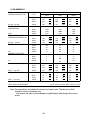
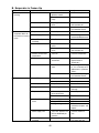
4. Controls and Adjustments
The dip switch is factory-adjusted to the positions outlined below.
For models with mechanical bin control.
Dip Switch No.
KM-280MAH-E
KM-500MAH-E
KM-630MAH-E
1
2
3
4
5
6
7
8
9
10
ON OFF OFF OFF OFF OFF ON OFF ON OFF
OFF OFF OFF OFF OFF OFF ON OFF ON OFF
OFF OFF OFF OFF OFF OFF ON OFF ON OFF
For models with bin thermostat.
Dip Switch No.
KM-280MAH-E
KM-500MAH-E
KM-630MAH-E
1
2
3
4
5
6
7
8
9
10
ON OFF OFF OFF OFF OFF OFF OFF ON OFF
OFF OFF OFF OFF OFF OFF OFF OFF ON OFF
OFF OFF OFF OFF OFF OFF OFF OFF ON OFF
Switch Nos. 1 and 2:
Used for adjustment of the defrost timer. The defrost timer starts counting when the
thermistor reads a certain temperature at the evaporator outlet.
Switch Nos. 3 and 4:
Used for adjustment of the drain timer. When a freeze cycle is completed, the pump
motor stops, and resumes operation in reverse after 2 seconds. Then the pump motor
drains the water tank for the time determined by the drain timer. The drain timer also
determines the time to restrain completion of a defrost cycle, i.e. the minimum defrost
time.
Switch Nos. 5 and 6:
Used for adjustment of the drain counter. The pump motor drains the water tank at the
frequency determined by the drain counter.
Switch No. 7:
Used only on models with mechanical bin control. Should be ON for models with
mechanical bin control, and OFF for models with bin thermostat.
Switch No. 8:
Used only for checking the controller board. Usually OFF.
Switch Nos. 9 and 10:
Used for adjustment of freeze
timer. The freeze timer
determines maximum freeze
cycle time. Upon termination of
freeze timer, machine initiates the
harvest cycle. After 2 consecutive
timer terminations, machine will
shut down, possibly indicating a
problem.
22
a) Defrost Control
A thermistor (semiconductor) is used for a defrost control sensor. The resistance varies
depending on the suction line temperatures. The thermistor detects the temperature of
the evaporator outlet to start the defrost timer. No adjustment is required. If necessary,
check for resistance between thermistor leads, and visually check the thermistor
mounting, located on the suction line next to the evaporator outlet.
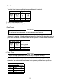
Temperature (°C)
Resistance (kΩ)
-18
-12
0
10
21
32
14.401
10.613
6.000
3.871
2.474
1.633
Check a thermistor for resistance by using the following procedures.
(1) Disconnect the connector K3 on the board.
(2) Remove the thermistor. See “V. H. Removal and Replacement of Thermistor.”
(3) Immerse the thermistor sensor portion in a glass containing ice and water for 2 or 3
minutes.
(4) Check for a resistance between thermistor leads.
Normal reading is within 3.5 to 7 kΩ. Replace the thermistor if it exceeds the normal
reading.
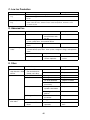
b) Defrost Timer
No adjustment is required under normal use, as the defrost timer is adjusted to the
suitable position. However, if necessary because all the ice formed on the evaporator
does not fall into the bin in the harvest cycle, adjust the defrost timer to a longer setting
by adjusting the dip switch (No. 1 & 2) on the controller board.
Dip Switch Setting
Time
No. 1
No. 2 (seconds)
OFF
OFF
60
ON
OFF
90
OFF
ON
120
ON
ON
180
23
c) Drain Timer
The drain timer is factory-adjusted and no adjustment is required.
Dip Switch Setting
No. 3
No. 4
OFF
OFF
ON
OFF
OFF
ON
ON
ON
Time (seconds)
T1
10
10
10
20
T2
150
180
120
180
T1: Time to drain the water tank
T2: Time to restrain defrost completion
d) Drain Counter
CAUTION
Do not adjust the drain counter, or the evaporator may freeze up.
The drain counter is factory-adjusted to drain the water tank every 10 cycles, and no
adjustment is required. However, where water quality is bad and the icemaker needs a
pump drain more often, the drain counter can be adjusted as shown in the table below.
Dip Switch Setting
Frequency
No. 5
No. 6
OFF
OFF
every cycle
ON
OFF
every 2 cycles
OFF
ON
every 5 cycles
ON
ON
every 10 cycles
e) Freeze Timer
CAUTION
Adjust to proper specification, or the unit may not operate correctly.
The freeze timer is factory adjusted and no adjustment is required. This setting
determines the maximum allowed freeze time to prevent possible freeze-up issues.
Dip Switch Setting
Time
No. 9
No. 10 (minutes)
OFF
OFF
60
OFF
ON
50
ON
OFF
70
ON
ON
75
24
f) Bin Control
(1) Models with Thermostat
CAUTION
When the ambient temperature is below 7°C, the bin control thermostat
operates to stop the icemaker even if the ice storage bin is empty. When the
thermostat is set in the prohibited range, the icemaker operates continuously
even if the ice storage bin is filled with ice. Setting in the prohibited range
might cause severe damage to the icemaker resulting in failure.
No adjustment is required under normal use, as the bin control is factory-adjusted.
Adjust it, if necessary, so that the icemaker stops automatically within 10 seconds after
ice contacts the bin control thermostat bulb.
(2) Models with Mechanical Bin Control
CAUTION
Dip switch no. 7 must be set to the ON position. If no. 7 is set to the OFF
position, the machine will run continuously, causing a freeze-up condition.
No adjustment is required. The bin control is factory-adjusted.
5. Checking the Controller Board
1) Visually check the sequence with the icemaker operating.
2) Visually check the controller board by using the following procedures:
(i) Adjust the defrost timer to minimum position.
Disconnect the thermistor (K3) from the controller board.
Connect a 1.5 kΩ - 3.5 kΩ resistor to the connector K3 (pins #1 and #2), and energize
the unit.
After the 1 minute ± 5 second water supply cycle and the 2 minute ± 10 second defrost
cycle, the unit should start the freeze cycle.
25
(ii) After the above step (i), disconnect the float switch leads (K5) from the controller board
within the first 5 minutes of the freeze cycle.
The unit should go into the defrost cycle after the first 5 minutes ± 20 seconds of the
freeze cycle.
(iii) Reconnect the float switch connector to the controller board. After the first 5 minutes of
the freeze cycle, disconnect the float switch leads from the controller board.
At this point, the unit should start the defrost cycle.
(iv) After step (iii), de-energize the unit and confirm that the defrost timer is in the minimum
position. Disconnect the resistor from the controller board, and energize the unit.
After the 1 minute water supply cycle, the defrost cycle starts.
Re-connect a 1.5 kΩ - 3.5 kΩ resistor to the connector K3 (pins #1 and #2) after the first
2 minutes of the defrost cycle. The unit should start the freeze cycle after 1 minute ± 5
seconds from the resistor connection.
3) Check the controller board using the controller board’s test program.
The output test switch “S3” provides a relay sequence test. With power OFF, place S3 on
and switch power to ICE. The correct lighting sequence should be none, 2, 3, 4, 1, and 4,
normal sequence every 5 seconds. S3 should remain in the “OFF” position for normal
operation.
D. Mechanical Bin Control
(These instructions are not applicable to models with thermostat.)
1. Proximity Switch
This machine uses a lever-actuated proximity switch (hereafter called “mechanical bin
control”) to control the ice level in the storage bin.
2. Explanation of Operation
a) The startup and shutdown of the ice machine is controlled via the controller board. Dip
switch number 7 must be in the ON position for the controller board to receive input from
the bin control.
(1) The controller board receives a resistance value input via the red K4 connector
from the bin control. A resistor wire harness is connected from the bin control to
the controller board.
(2) When the bin control is activated in the bin full position (pushed to the right), a
15.8 KΩ signal will be sent to the control board to shut down the unit.
(3) When the bin control is in the normal position (bin is not full), a 7.9 KΩ reading is
sent to the control board to continue operation.
26
b) During operation, the controller board will only shut down the machine if a 15.8 KΩ signal
is received from the bin control during the first 5 minutes of the freeze cycle.
(1) If ice pushes the lever to the right after the first five minutes of the freeze cycle,
the controller board will allow the machine to complete the freeze cycle and the
following harvest cycle before shutting down the machine. This will prevent
incomplete batches of ice from forming on the evaporator.
3. Troubleshooting (Mechanical Bin Control Only)
a) Machine will not start
(1) Move dip switch No. 7 to the “OFF” position. If the machine starts up within a few
seconds, the bin control is the likely problem. If the machine does not start up,
refer to Section “IV. Service Diagnosis” to verify that non-bin control related issues
are resolved.
(2) Check to make sure shipping tape has been removed and the wires are connected
properly.
(3) Check to make sure no obstruction prevents the lever from moving to the bin empty
position.
b) Machine will not shut off
(1) Refer to Section “IV. Service Diagnosis” to verify that non-bin control related issues
are resolved.
(2) Dip switch No. 7 should be in the on position. If the switch is in the off position, the
controller board will not receive input from the bin control.
(3) Move the lever to the far right.
(a) If the machine does not shut off, check the resistance values of the resistor wire
harness. You should read approximately 15.8 KΩ between the black terminal and
the red terminal that connect to the K4 connector on the controller board, when the
lever is in the bin full position (far right). If this reads approximately 7.9 KΩ, the
resistors may be miswired. Switch the black and white wires in the terminal
housing or order a replacement wire harness.
(b) Check the stainless steel bracket that the bin control is mounted to.
(c) If the preceding items do not resolve the problem, replace the bin control
assembly.
27
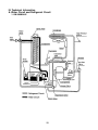
III. Technical Information
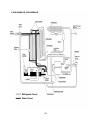
A. Water Circuit and Refrigerant Circuit
1. KM-280MAH-E
28
2. KM-500MAH-E, KM-630MAH-E
29
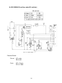
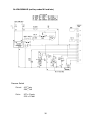
B. Wiring Diagrams
1a. KM-280MAH-E (auxiliary codes L-0 through M-1)
Pressure Switch
Cut-out
412 +21
- 0 psig
28.4 +1.5
- 0 bar
Cut-in
327 ± 21 psig
22.5 ± 1.5 bar
30
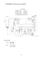
1b. KM-280MAH-E (auxiliary codes M-2 and later)
Pressure Switch
Cut-out
412 +21
- 0 psig
28.4 +1.5
- 0 bar
Cut-in
327 ± 21 psig
22.5 ± 1.5 bar
31
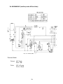
2a. KM-500MAH-E (auxiliary codes L-0 through M-1)
Pressure Switch
Cut-out
412 +21
- 0 psig
28.4 +1.5
- 0 bar
Cut-in
327 ± 21 psig
22.5 ± 1.5 bar
32
2b. KM-500MAH-E (auxiliary codes M-2 and later)
Pressure Switch
Cut-out
412 +21
- 0 psig
28.4 +1.5
- 0 bar
Cut-in
327 ± 21 psig
22.5 ± 1.5 bar
33
3a. KM-630MAH-E (auxiliary codes L-0 through M-1)
Pressure Switch
Cut-out
412 +21
- 0 psig
28.4 +1.5
- 0 bar
Cut-in
327 ± 21 psig
22.5 ± 1.5 bar
34
3b. KM-630MAH-E (auxiliary codes M-2 and later)
Pressure Switch
Cut-out
412 +21
- 0 psig
28.4 +1.5
- 0 bar
Cut-in
327 ± 21 psig
22.5 ± 1.5 bar
35
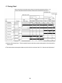
C. Timing Chart
*1 Mechanical Bin Control Only—The bin control will only shut off the ice machine during the first five minutes of the
freeze cycle.
*2 The icemaker does not complete a defrost cycle in the first 2 or 3 minutes. See “II.C.4. Controls and Adjustments.”
36
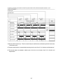
*1 Mechanical Bin Control Only—The bin control will only shut off the ice machine during the first five minutes
of the freeze cycle.
*2 The pump motor waits for 2 seconds before starting a drain cycle. See “II.C.4. Controls and Adjustments.”
*3 The icemaker does not complete a defrost cycle in the first 2 or 3 minutes. See “II.C.4. Controls and
Adjustments.”
37
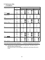
D. Performance Data
1. KM-280MAH-E
APPROXIMATE ICE
PRODUCTION PER 24 HR.
lbs./day kg./day
APPROXIMATE ELECTRIC
CONSUMPTION
watts
APPROXIMATE WATER
CONSUMPTION PER 24 HR.
3
gal./day m /day
FREEZING CYCLE TIME
min.
HARVEST CYCLE TIME
min.
HEAD PRESSURE
PSIG
2
kg/cm G
SUCTION PRESSURE
PSIG
2
kg/cm G
WATER TEMP. (ºF/ºC)
AMBIENT TEMP.
(ºF/ºC)
50/10
70/21
90/32
70/21
258
117
231
105
204
93
80/27
237
108
196
89
175
79
90/32
100/38
231
229
105
104
166
160
75
73
142
120
64
54
70/21
763
775
783
80/27
90/32
772
775
790
802
795
809
100/38
70/21
99
0.37
87
0.33
77
0.29
80/27
90
0.34
72
0.27
64
0.24
90/32
87
0.33
59
0.22
50
0.19
100/38
80
0.30
50
0.19
41
0.16
789
804
815
70/21
80/27
20
22
23
28
30
35
90/32
23
31
39
100/38
25
33
45
70/21
3.1
3.1
3.0
80/27
90/32
3.1
3.1
3.0
2.9
2.5
2.9
100/38
3.0
2.9
2.9
70/21
245
17.2
267
18.8
290
20.4
80/27
262
18.4
296
20.8
315
22.1
90/32
267
18.8
320
22.5
341
24.0
100/38
269
18.9
325
22.8
360
25.3
70/21
55
3.9
58
4.1
61
4.3
80/27
57
4.0
62
4.3
64
4.5
90/32
58
4.1
65
4.6
68
4.8
100/38
58
4.1
66
4.6
70
4.9
8159 BTU/h [AT 90ºF (32ºC) / WT 70ºF (21ºC)]
TOTAL HEAT OF REJECTION FROM CONDENSER
Note: Pressure data is recorded at 5 minutes into freeze cycle. The data not in bold
should be used for reference only.
We reserve the right to make changes in specifications and design without prior
notice.
38
2. KM-500MAH-E
APPROXIMATE ICE
PRODUCTION PER 24 HR.
lbs./day kg./day
APPROXIMATE ELECTRIC
CONSUMPTION
watts
APPROXIMATE WATER
CONSUMPTION PER 24 HR.
3
gal./day m /day
FREEZING CYCLE TIME
min.
HARVEST CYCLE TIME
min.
HEAD PRESSURE
PSIG
2
kg/cm G
SUCTION PRESSURE
PSIG
2
kg/cm G
WATER TEMP. (°F/°C)
AMBIENT TEMP.
(°F/°C)
50/10
70/21
90/32
70/21
480
218
446
202
403
183
80/27
454
206
402
182
360
163
90/32
446
202
365
166
321
146
100/38
438
199
355
161
281
127
70/21
940
963
1039
80/27
958
994
1095
90/32
963
1019
1111
1041
993
1196
100/38
70/21
242
0.92
215
0.81
193
0.73
80/27
222
0.84
179
0.68
166
0.63
90/32
215
0.81
149
0.56
132
0.50
100/38
194
0.73
145
0.55
116
0.44
70/21
80/27
29
31
32
36
37
41
90/32
32
39
44
100/38
33
40
50
70/21
3.4
3.3
3.2
80/27
90/32
3.3
3.3
3.1
2.9
3.0
2.9
3.3
100/38
2.9
2.8
70/21
250
17.6
268
18.8
293
20.6
80/27
263
18.5
291
20.4
316
22.3
90/32
268
18.8
310
21.8
336
23.6
100/38
273
19.2
316
22.2
360
25.3
70/21
50
3.5
53
3.7
55
3.8
80/27
52
3.7
56
3.9
57
4.0
90/32
53
3.7
59
4.1
61
4.3
100/38
53
3.7
59
4.2
62
4.4
TOTAL HEAT OF REJECTION
7371 BTU/h [AT 90°F (32°C) / WT 70°F (21°C)
Note: Pressure data is recorded at 5 minutes into freeze cycle. The data not in bold
should be used for reference only.
We reserve the right to make changes in specifications and design without prior
notice.
39
3. KM-630MAH-E
APPROXIMATE ICE
PRODUCTION PER 24 HR.
lbs./day kg./day
APPROXIMATE ELECTRIC
CONSUMPTION
watts
APPROXIMATE WATER
CONSUMPTION PER 24 HR.
3
gal./day m /day
FREEZING CYCLE TIME
min.
HARVEST CYCLE TIME
min.
HEAD PRESSURE
PSIG
2
kg/cm G
SUCTION PRESSURE
PSIG
2
kg/cm G
WATER TEMP. (°F/°C)
AMBIENT TEMP.
(°F/°C)
50/10
70/21
90/32
70/21
624
283
576
261
520
236
80/27
587
266
513
233
463
210
90/32
576
261
460
209
406
184
100/38
568
258
447
203
357
162
70/21
1300
1329
1361
80/27
1322
1367
1395
90/32
1329
1399
1430
100/38
70/21
208
0.79
192
0.73
173
0.66
80/27
195
0.74
170
0.65
154
0.58
90/32
192
0.73
153
0.58
135
0.51
100/38
189
0.72
149
0.56
119
0.45
1333
1406
1458
70/21
80/27
32
35
35
40
42
47
90/32
35
44
51
100/38
37
45
57
70/21
3
3
3
80/27
90/32
3
3
3
2.9
3
2.9
100/38
3
2.8
2.8
70/21
270
19.0
291
20.4
309
21.7
80/27
286
20.1
318
22.3
330
23.2
90/32
291
20.4
340
23.9
356
25.0
100/38
291
20.5
344
24.2
370
26.0
70/21
50
3.5
51
3.6
52
3.7
80/27
50
3.5
51
3.6
53
3.7
90/32
51
3.6
52
3.7
54
3.8
100/38
51
3.6
52
3.7
55
3.9
10375 BTU/h [AT 90°F (32°C) / WT 70°F (21°C
TOTAL HEAT OF REJECTION
Note: Pressure data is recorded at 5 minutes into freeze cycle. The data not in bold
should be used for reference only.
We reserve the right to make changes in specifications and design without prior
notice.
40
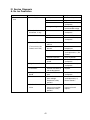
IV. Service Diagnosis
A. No Ice Production
Problem
Possible Cause
[1] The icemaker will not a) Power Supply
start.
Remedy
1. OFF position.
1. Move to ON position.
2. Loose connection.
2. Tighten.
3. Bad contacts.
3. Check for continuity
and replace.
4. Voltage too high.
4. Check and get
recommended voltage.
1. Check for short circuit
and replace.
b) Fuse (Inside fused
disconnect, if any)
1. Blown.
c) Control Switch
1. OFF position.
1. Move to ICE position.
2. Bad contacts.
2. Check for continuity
and replace.
d) Bin Control Thermostat 1. Tripped with bin filled
with ice.
(For mechanical bin
2. Ambient temperature
control, see II.D.3.)
too cool.
1. Remove ice.
2. Increase ambient
temperature.
3. Set too warm.
3. See "II.C.4. Controls
and Adjustments, f) Bin
Control."
4. Bulb out of position.
4. Place in position.
5. Bad contacts or leaks
in bulb.
5. Check for continuity
and replace.
e) High Pressure Control
1. Bad contacts.
1. Check for continuity
and replace.
f) Transformer
1. Thermal fuse blown or
coil winding opened.
1. Replace.
g) Wiring to Controller
Board
1. Loose connections or
open.
1. Check for continuity
and replace.
h) Thermistor
1. Leads short-circuit or
open and high
temperature safety
operates.
1. See "II.C.4. Controls
and Adjustments, a)
Defrost Control."
i) Hot Gas Solenoid
Valve
1. Continues to open in
freeze cycle and high
temperature safety
operates.
1. Check for power off in
freeze cycle and
replace.
41
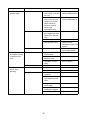
Problem
Possible Cause
Remedy
[1] Continued from
previous page.
j) Water Supply Line
1. Water supply off and
1. Check and get
water supply cycle does
recommended pressure.
not finish.
2. Condenser water
2. Check and get
pressure too low or off
recommended pressure.
and pressure control
opens and closes
frequently to finally
operate high
temperature safety.
k) Water Solenoid
1. Mesh filter or orifice
1. Clean.
gets clogged and water
supply cycle does not
finish.
2. Coil winding opened.
2. Replace.
3. Wiring to water valve.
[2] Water continues to
be supplied, and the
icemaker will not
start.
[3] Compressor will not
start or stops
operating.
3. Check for loose
connection or open, and
replace.
1. See "II.C.5. Checking
the Controller Board."
l) Controller Board
1. Defective.
a) Float Switch
1. Connector
disconnected.
2. Leads opened or
defective switch.
1. Place in position.
3. Float does not move
freely.
3. Clean or replace.
b) Controller Board
1. Defective.
1. Replace.
a) Wash Switch
1. WASH position.
1. Move to ICE position.
2. Bad contacts.
2. Check and replace.
1. Dirty air filter or
condenser.
1. Clean.
2. Ambient or condenser
water temperature too
warm.
2. Reduce temperature.
3. Refrigerant
overcharged.
3. Recharge.
4. Refrigerant line or
components plugged.
4. Clean and replace drier.
5. Fan not operating.
5. See chart A.[6]
b) High Pressure Control
42
2. Check and replace.
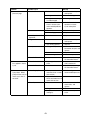
Problem
Possible Cause
[3] Continued from
previous page.
c) Overload Protector
Remedy
1. Bad contacts.
1. Check for continuity
and replace.
2. Voltage too low.
2. Increase voltage.
3. Refrigerant overcharged 3. Recharge.
or undercharged.
4. Line valve continues to 4. Check line valve's
operation in freeze
close in freeze cycle
cycle and replace.
and overload protector
operates.
d) Starter
1. Bad contacts.
1. Check and replace.
2. Coil winding opened.
2. Replace.
e) Start Capacitor or Run 1. Defective.
Capacitor
1. Replace.
f) Magnetic Contactor
1. Bad contacts.
1. Check for continuity
and replace.
2. Coil winding opened.
2. Replace.
1. Wiring to compressor.
2. Defective.
1. Check for loose
connection or open, and
replace.
2. Replace.
3. Protector tripped.
3. Reduce temperature.
1. Defective.
1. See "II.C.5. Checking
the Controller Board."
1. Diaphragm does not
close.
1. Check for water leaks
with icemaker off.
1. Defective.
1. See "II.C.5. Checking
the Controller Board."
g) Compressor
h) Controller Board
[4] Water continues to
a) Water Solenoid Valve
be supplied in freeze
cycle.
b) Controller Board
[5] No water comes from a) Water Supply Line
spray tubes. Water
pump will not start, or
freeze cycle time is b) Water Solenoid Valve
too short.
c) Water System
1. Water pressure too low 1. Check and get
and water level in water
recommended pressure.
tank too low.
1. Dirty mesh filter or
1. Clean.
orifice and water level in
water tank too low.
1. Water leaks.
1. Check connections for
water leaks, and
replace.
2. Clogged.
2. Clean.
3. Pump out check valve
leaking by.
43
3. Check assembly and
clean.
Problem
Possible Cause
[5] Continued from
previous page.
d) Pump Motor
Remedy
1. Motor winding opened.
1. Replace.
2. Bearing worn out.
2. Replace.
3. Wiring to pump motor.
3. Check for loose
connection or open, and
replace.
4. Replace.
4. Defective capacitor.
[6] Fan motor will not
start, or is not
operating.
[7] All components run,
but no ice is
produced.
5. Defective or bound
impeller.
5. Replace and clean.
6. Check and replace.
e) Controller Board
6. Mechanical seal worn
out.
1. Defective.
a) Fan Motor
1. Motor winding opened.
1. Replace.
2. Bearing worn out.
2. Replace.
3. Wiring to fan motor.
4. Defective capacitor.
3. Check for loose
connection or open, and
replace.
4. Replace.
5. Fan blade bound.
5. Check and replace.
b) Controller Board
1. Defective.
1. See "II.C.5. Checking
the Controller Board."
a) Refrigerant
1. Undercharged.
1. Check for leaks and
recharge.
1. See "II.C.5. Checking
the Controller Board."
2. Air or moisture trapped. 2. Replace drier and
recharge.
b) Compressor
1. Defective valve.
1. Replace.
c) Hot Gas Solenoid
Valve
1. Continues to open in
freeze cycle.
1. Check and replace.
44
B. Evaporator is Frozen Up
Problem
Possible Cause
[1] Freeze cycle time is
too long.
a) Float Switch
1. Leads short-circuit or
defective switch.
1. Check and replace.
2. Float does not move
freely.
2. Clean or replace.
b) Water Solenoid Valve
1. Diaphragm does not
close.
1. Check for water leaks
with icemaker off.
c) Controller Board
1. Defective.
1. See "II.C.5. Checking
the Controller Board."
1. Scaled up.
1. Clean.
[2] All ice formed on
a) Evaporator
evaporator does not b) Water Supply Line
fall into bin in harvest
cycle.
c) Water Filter System (if
installed)
d) Water Solenoid Valve
1. Water pressure too low. 1. Check and get
recommended pressure.
1. Dirty/Restricted
1. Replace filter.
1. Dirty mesh filter or
orifice.
2. Diaphragm does not
close.
1. Clean.
2. Check for water leaks
with icemaker off.
e) Ambient and/or water
temperature.
1. Too cool.
1. Increase temperature.
f) Thermistor
1. Out of position or loose 1. See "V.H. Removal and
attachment.
Replacement of
Thermistor."
1. Defrost timer is set too 1. Adjust longer, referring
short.
to "II.C.4. Controls and
Adjustments, b) Defrost
Timer."
g) Controller Board
[3] Other
Remedy
2. Defective.
2. See "II.C.5. Checking
the Controller Board."
1. Clogged.
1. Clean.
2. Out of position.
2. Place in position.
b) Water System
1. Dirty.
1. Clean.
c) Refrigerant
1. Undercharged.
1. Check for leaks and
recharge.
d) Expansion Valve
1. Bulb out of position or
loose attachment.
1. Place in position.
2. Defective.
2. Replace.
1. Coil winding opened.
1. Replace.
a) Spray Tubes
e) Hot Gas Solenoid
Valve
f) Water Supply Line
g) Water Filter (if
installed)
2. Plunger does not move. 2. Replace.
3. Wiring to hot gas valve. 3. Check for loose
connection or open, and
replace.
1. Too small; requires 3/8" 1. Increase water line
size.
OD line dedicated per
machine.
1. Flow rate too small.
1. Replace with filter that
has larger flow rate.
45
C. Low Ice Production
P roblem
P ossible Cause
Rem edy
[1] Freez e c y c le tim e is
long.
a) S ee c hart A .[3] and c hec k high pres s ure c ontroller.
b) S ee c hart B .[1] and c hec k float s witc h, water s olenoid v alv e and c ontroller
board.
[2] Harv es t c y c le tim e is a) S ee c hart B .[2] and c hec k ev aporator, water s upply line, water filter s y s tem ,
long.
water s olenoid v alv e, am bient and/or water tem perature, therm is tor, and
c ontroller board.
D. Abnormal Ice
Problem
Possible Cause
[1] Small cubes.
a) Ice Cube Guide
1. Out of position.
1. Place in position.
Circulated water falls
into bin.
b) See chart A.[5] and check water supply line, water solenoid valve, water
system, pump motor, and controller board.
c) Pump Out Check
Valve
[2] Cloudy or irregular
cubes.
Remedy
1. Dirty.
1. Clean.
a) See chart B.[1] and B.[3], and check float switch, water solenoid valve,
controller board, spray tubes, water system, refrigerant charge, and expansion
valve.
1. Dirty.
1. Clean.
b) Spray Guide
c) Water Quality
1. High hardness or
contains impurities.
1. Install a water softener
or filter.
E. Other
Problem
Possible Cause
Remedy
[1] Icemaker will not
a) Bin Control Thermostat 1. Set too cold.
stop when bin is filled
(For mechanical bin
2. Defective.
with ice.
control, see II.D.3.)
[2] Abnormal noise.
a) Pump Motor
1. Bearings worn out.
b) Fan Motor
c) Compressor
[3] Ice in storage bin
often melts.
1. Adjust warmer.
2. Replace.
1. Replace.
1. Bearings worn out.
1. Replace.
2. Fan blade deformed.
2. Replace fan blade.
3. Fan blade does not
move freely.
3. Replace.
1. Bearings worn out or
cylinder valve broken.
1. Replace.
2. Mounting pad out of
position.
2. Reinstall.
d) Refrigerant Lines
1. Rub or touch other lines 1. Replace.
or surfaces.
a) Bin Drain
1. Plugged.
1. Clean.
b) Icemaker and Bin
Drains
1. Drains not run
separately.
1. Separate the drain
lines.
46
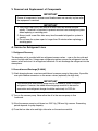
V. Removal and Replacement of Components
IMPORTANT
Ensure all components, fasteners and thumbscrews are securely in place after
the equipment is serviced.
IMPORTANT
1. The Polyol Ester (POE) oils used in R-404A units can absorb moisture
quickly. Therefore it is important to prevent moisture from entering the system
when replacing or servicing parts.
2. Always install a new filter drier every time the sealed refrigeration system is
opened.
3. Do not leave the system open for longer than 15 minutes when replacing or
servicing parts.
A. Service for Refrigerant Lines
1. Refrigerant Recovery
The icemaker unit is provided with two refrigerant access valves – one on the low-side and
one on the high-side line. Using proper refrigerant practices recover the refrigerant from the
access valves and store it in an approved container. Do not discharge the refrigerant into the
atmosphere.
2. Evacuation and Recharge [R-404A]
1) Attach charging hoses, a service manifold and a vacuum pump to the system. If possible,
use quick-release connectors on the access valves (especially the high side).
IMPORTANT
The vacuum level and vacuum pump may be the same as those for current
refrigerants. However, the rubber hose and gauge manifold to be used for
evacuation and refrigerant charge should be exclusively for POE oils.
2) Turn on the vacuum pump. Never allow the oil in the vacuum pump to flow
backward.
3) Allow the vacuum pump to pull down to a 29.9" Hg (760 mm Hg) vacuum. Evacuating
period depends on pump capacity.
4) Close the low-side valve and high-side valve on the service manifold.
47
5) Disconnect the vacuum pump, and attach a refrigerant service cylinder to the high-side
line. Remember to loosen the connection, and purge the air from the hose. See the
nameplate for the required refrigerant charge. Hoshizaki recommends only virgin
refrigerant or reclaimed refrigerant which meets ARI Standard No. 700-88 be used.
6) A liquid charge is recommended for charging an R-404A system. Invert the service
cylinder. Open the high-side, service manifold valve.
7) Allow the system to charge with liquid until the pressures balance.
8) If necessary, add any remaining charge to the system through the low-side. Use a
throttling valve or liquid dispensing device to add the remaining liquid charge through
the low-side access port with the unit running.
9) Close the two refrigerant access valves and disconnect the hoses and service manifold.
10) Cap the access valves to prevent a possible leak.
B. Brazing
DANGER
1. Refrigerant R-404A itself is not flammable at atmospheric pressure and
temperatures up to 80°C.
2. Refrigerant R-404A itself is not explosive or poisonous. However, when
exposed to high temperatures (open flames) R-404A can be decomposed to
form hydrofluoric acid and carbonyl fluoride both of which are hazardous.
3. Always recover the refrigerant and store it in an approved container. Do not
discharge the refrigerant into the atmosphere.
4. Do not use silver alloy or copper alloy containing arsenic.
5. Do not use R-404A as a mixture with pressurized air for leak testing.
Refrigerant leaks can be detected by charging the unit with a little refrigerant,
raising the pressure with nitrogen and using an electronic leak detector.
Note: All brazing-connections inside the evaporator case are clear-paint coated.
Sandpaper the brazing connections before unbrazing the components. Use a
good abrasive cloth to remove coating.
48
C. Removal and Replacement of Compressor
IMPORTANT
Always install a new drier every time the sealed refrigeration system is opened.
Do not replace the drier until after all other repair or replacement has been
made.
Note: When replacing a compressor with a defective winding, be sure to install the new
start capacitor and start relay supplied with the replacement compressor. Due to
the ability of the POE oil in the compressor to absorb moisture quickly, the
compressor must not be opened more than 15 minutes for replacement or service.
Do not mix lubricants of different compressors even if both are charged with
R-404A, except when they use the same lubricant.
1) Turn off the power supply, and unplug the icemaker.
2) Remove the panels.
3) Recover the refrigerant and store it in an approved container. (See “V.A.1. Refrigerant
Recovery”.)
4) Remove the terminal cover on the compressor, and disconnect the compressor wiring.
5) Remove the discharge and suction pipes using brazing equipment.
6) Remove the hold-down bolts, washers and rubber grommets.
7) Slide and remove the compressor. Unpack the new compressor package. Install the new
compressor.
8) Attach the rubber grommets of the prior compressor.
9) Sandpaper the suction, discharge and process pipes.
10) Place the compressor in position, and secure it using the bolts and washers.
11) Remove plugs from the suction, discharge and process pipes.
12) Braze the process, suction and discharge lines (Do not change this order), while
purging with nitrogen gas flowing at a pressure of 3 to 4 psig (.21 to .28 bar).
13) Install the new filter drier. (See “V.D. Removal and Replacement of Drier”.)
14) Check for leaks using nitrogen gas at 140 psig (9.65 bar) and soap bubbles.
15) Evacuate the system, and charge it with refrigerant. See the nameplate for the required
refrigerant charge. (See “V.A.2. Evacuation and Recharge [R-404A]”.)
49
16) Connect the terminals, and replace the terminal cover in its correct position.
17) Replace the panels in their correct positions.
18) Plug in the icemaker. Turn on the power supply.
D. Removal and Replacement of Drier
IMPORTANT
Always install a new drier every time the sealed refrigeration system is
opened. Do not replace the drier until after all other repair or replacement has
been made.
1) Turn off the power supply. Unplug the icemaker.
2) Remove the panels.
3) Recover the refrigerant and store it in an approved container. (See “V.A.1. Refrigerant
Recovery”.)
4) Remove the drier.
5) Install the new drier with the arrow on the drier in the direction of the refrigerant flow.
Use nitrogen gas at a pressure of 3 to 4 psig (.21 to .28 bar) when brazing the tubings.
6) Check for leaks using nitrogen gas at 140 psig (9.65 bar) and soap bubbles.
7) Evacuate the system and charge it with refrigerant. See the nameplate for the required
refrigerant charge. (See “V.A.2. Evacuation and Recharge [R-404A]”.)
8) Replace the panels in their correct positions.
9) Plug in the icemaker. Turn on the power supply.
50
E. Removal and Replacement of Expansion Valve
IMPORTANT
Sometimes moisture in the refrigerant circuit exceeds the drier capacity and
freezes up at the expansion valve. Always install a new drier every time the
sealed refrigeration system is opened. Do not replace the drier until after all
other repair or replacement has been made.
1) Turn off the power supply. Unplug the icemaker.
2) Remove the panels.
3) Recover the refrigerant and store it in an approved container. (See “V.A.1. Refrigerant
Recovery”.)
4) Remove the insulation and the expansion valve bulb on the suction line.
5) Remove the expansion valve cover, and disconnect the expansion valve using
brazing equipment. Protect adjacent components from excessive heat using damp cloths
or similar.
6) Braze the new expansion valve, with nitrogen gas flowing at a pressure of 3 to 4 psig (.21
to .28 bar).
WARNING
1. Do not heat the wall. Place a steel barrier for protection.
2. Always protect the valve body by using a damp cloth to prevent the valve
from overheating. Do not braze with the valve body exceeding 121°C.
7) Install the new drier.
8) Check for leaks using nitrogen gas at 140 psig (9.65 bar) and soap bubbles.
9) Evacuate the system, and charge it with refrigerant. See the nameplate for the required
refrigerant charge. (See “V.A.2. Evacuation and Recharge [R-404A]”.)
10) Attach the bulb to the suction line in position. Be sure to secure it with clamps and to
insulate it.
11) Place the new set of expansion valve covers in position.
12) Replace the panels in their correct position.
13) Plug in the icemaker. Turn on the power supply.
51
F. Removal and Replacement of Hot Gas Valve
CAUTION
Always use a copper tube of the same diameter and length when replacing the
hot gas lines; otherwise performance may be reduced.
IMPORTANT
Always install a new drier every time the sealed refrigeration system is opened.
Do not replace the drier until after all other repair or replacement has been
made.
1) Turn off the power supply. Unplug the icemaker.
2) Remove the panels.
3) Recover the refrigerant and store it in an approved container. (See “V.A.1. Refrigerant
Recovery”.)
4) Remove the screw and the solenoid.
5) Disconnect the hot gas valve or line valve using brazing equipment.
6) Install the new valve, with nitrogen gas flowing at a pressure of 3 to 4 psig (.21 to .28 bar).
WARNING
Always protect the valve body by using a damp cloth to prevent the valve from
overheating. Do not braze with the valve body exceeding 121°C.
7) Install the new drier.
8) Check for leaks using nitrogen gas at 140 psig (9.65 bar) and soap bubbles.
9) Evacuate the system and charge it with refrigerant. See the nameplate for the required
refrigerant charge. (See “V.A.2. Evacuation and Recharge [R-404A]”.)
10) Cut the leads of the solenoid allowing enough lead length to reconnect using closed
end connectors.
11) Connect the new solenoid leads.
12) Attach the solenoid to the valve body, and secure it with a screw.
52
13) Replace the panels in their correct positions.
14) Plug in the icemaker. Turn on the power supply.
G. Removal and Replacement of Evaporator
IMPORTANT
Always install a new drier every time the sealed refrigeration system is opened.
Do not replace the drier until after all other repair or replacement has been
made.
1) Turn off the power supply. Unplug the icemaker.
2) Remove the panels and the top and front insulation from the evaporator.
3) Recover the refrigerant and store it in an approved container. (See “V.A.1. Refrigerant
Recovery”.)
4) Remove the spray tubes and the insulations at the “U” shaped notch where the
refrigeration tubings go through the chassis.
5) Remove the insulation tube and disconnect the evaporator inlet tubing at the tee next to
the expansion valve using brazing equipment. (Protect the valve from excessive heat.)
6) Lift up the evaporator, and disconnect the evaporator outlet tubing.
7) Install the new evaporator, with nitrogen gas flowing at a pressure of 3 to 4 psig (.21 to
.28 bar).
8) Install the new drier.
9) Check for leaks using nitrogen gas at 140 psig (9.65 bar) and soap bubbles.
10) Evacuate the system, and charge it with refrigerant. See the nameplate for the required
refrigerant charge. (See “V.A.2. Evacuation and Recharge [R-404A]”.)
11) Replace the removed parts in the reverse order of which they were removed.
12) Replace the top and front insulation and the panels in their correct positions.
13) Plug in the icemaker. Turn on the power supply.
53
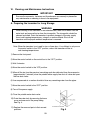
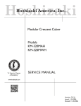
H. Removal and Replacement of Thermistor
CAUTION
1. Fragile, handle very carefully.
2. Always use a recommended sealant (high thermal conductive type), Model
KE4560RTV manufactured by Shinetsu Silicone, Part Code 60Y000-11, or
Part Code 4A0683-01, or equivalent.
3. Always use a recommended foam insulation (non-absorbent type) or
equivalent.
4. Do not shorten or cut the thermistor leads when installing it.
Thermistor Lead
1) Turn off the power supply. Unplug the icemaker.
Cable Tie
2) Remove the panels.
3) Remove the control box cover.
4) Disconnect the thermistor leads from
the K3 connector on the controller board.
5) Remove the plastic cable ties, foam
insulation, thermistor holder and
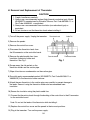
thermistor. See Fig. 1.
Foam Insulation
Thermistor Holder
Fig. 1
6) Scrape away the old sealant on the
thermistor holder and the suction pipe.
7) Wipe off moisture or condensation on the suction pipe.
8) Smoothly apply recommended sealant (KE4560RTV, Part Code 60Y000-11 or
4A0683-01) to the thermistor holder concave.
9) Attach the new thermistor to the suction pipe very carefully to prevent damage to
the leads. Secure it using the thermistor holder and recommended foam
insulation.
10) Secure the insulation using the plastic cable ties.
11) Connect the thermistor leads through the bushing of the control box to the K3 connector
on the controller board.
Note: Do not cut the leads of the thermistor while installing it.
12) Replace the control box cover and the panels in their correct positions.
13) Plug in the icemaker. Turn on the power supply.
54
I. Removal and Replacement of Fan Motor
Note: When replacing a fan motor with defective winding, it is recommended that a new
capacitor be installed.
1) Turn off the power supply. Unplug the icemaker.
2) Remove the panels.
3) Remove the closed end connectors from the fan motor leads.
4) Remove the fan motor bracket and fan motor.
5) Install the new fan motor, and replace the removed parts in the reverse order of which
they were removed.
6) Replace the panels in their correct positions.
7) Plug in the icemaker. Turn on the power supply.
55
J. Removal and Replacement of Water Valve
1) Turn off the power supply. Unplug the icemaker.
2) Close the water supply line shut-off valve.
3) Remove the top panel and front panel.
4) Remove the valve outlet tubing by releasing the clamp.
5) Remove the bracket from the unit.
6) Remove the fitting nut and water valve. (Do not lose the packing/gasket.)
7) Disconnect the terminals from the water valve.
8) Install the new water valve, and replace the removed parts in the reverse order of
which they were removed.
9) Open the water supply line shut-off valve.
10) Plug in the icemaker. Turn on the power supply.
11) Check for leaks.
12) Replace the top and front panels in their correct positions.
K. Removal and Replacement of Pump Motor
Note: When replacing a pump motor with defective winding, it is recommended that a
new capacitor be installed.
1) Turn off the power supply. Unplug the icemaker.
2) Remove the front panel.
3) Remove the base cover.
4) Drain the water tank by removing one end of the pump tubing. (See Fig. 2.) Refit the
hose back into position.
5) Disconnect the pump suction and discharge hoses.
6) Remove the closed end connectors from the
pump motor leads.
7) Remove the two screws to remove the pump complete
with the bracket. Remove the bracket from the pump.
56
Fig. 2
8) Remove the pump housing and check the impeller.
9) If the impeller is defective, install a new impeller.
10) Install the new motor or new parts, and replace the removed parts in the reverse
order of which they were removed.
11) Plug in the icemaker. Turn on the power supply and check for leaks.
12) Replace the base cover in its correct position.
13) Replace the front panel in its correct position.
L. Removal and Replacement of Float Switch
1) Turn off the power supply. Unplug the icemaker.
2) Remove the front panel.
3) Remove the base cover.
4) Drain the water tank by removing one end of the pump tubing. (See Fig. 3.) Refit the hose
back into position.
5) Remove the black rubber connector from the base of the float switch.
6) Remove the screws securing the float switch bracket and
the stainless steel adjusting guide.
7) Take off the hose sleeving the float switch leads.
8) Sleeve the leads of the new float switch with the hose.
9) Install the new float switch, and replace the removed parts in the reverse order of
which they were removed.
10) Plug in the icemaker. Turn on the power supply and check for leaks.
11) Replace the base cover in its correct position.
12) Replace the front panel in its correct position.
57
Fig. 3
M. Removal and Replacement of Spray Tubes
1) Turn off the power supply. Unplug the icemaker.
2) Remove the front panel and the insulation panel.
3) Remove the rubber hoses from the spray tubes (water supply pipe).
4) Release the clamps and disconnect the rubber hoses.
5) Remove the spray tubes by squeezing the side tabs.
6) Install the new spray tubes, and replace the removed parts in the reverse order of which
they were removed.
7) Replace the panels in their correct positions.
8) Plug in the icemaker. Turn on the power supply.
N. Removal and Replacement of Transformer
1) Turn off the power supply. Unplug the icemaker.
2) Remove the panels.
3) Remove the closed end connectors from the transformer leads.
4) Remove the transformer cover.
5) Remove the transformer.
6) Install the new transformer.
7) Replace the transformer cover.
8) Install new closed end connectors.
9) Refit the panels.
10) Plug in the icemaker. Turn on the power supply.
58
VI. Cleaning and Maintenance Instructions
IMPORTANT
Ensure all components, fasteners and thumbscrews are securely in place after
any maintenance or cleaning is done to the equipment.
A. Preparing the Icemaker for Long Storage
WARNING
When shutting off the icemaker for an extended time, drain out all water from the
water tank and remove the ice from the storage bin. The storage bin should be
cleaned and dried. Drain the icemaker to prevent damage to the water supply
line at sub-freezing temperatures, using air or carbon dioxide. Shut off the
icemaker until the proper ambient temperature is resumed.
Note: When the icemaker is not used for two or three days, it is sufficient to only move
the control switch to the “OFF” position, unless the icemaker will be at
sub-freezing temperatures.
1) Remove the front panel.
2) Move the control switch on the control box to the “OFF” position.
3) Wait 3 minutes.
4) Move the control switch to the “ICE” position.
5) When all the ice from the previous ice making cycle has defrosted from the evaporator,
(approximately 2 minutes) close the potable water supply line shut-off valve and open
the line drain valve.
6) Use compressed air or carbon dioxide to blow any remaining water from the pipes.
7) Move the control switch to the “OFF” position.
8) Turn off the power supply.
9) Close the potable water drain valve.
10) Drain the water tank by removing the base
cover and one end of the pump tubing.
See Fig. 4.
11) Replace the removed parts in their correct
positions.
59
Fig. 4
12) Remove all ice from the storage bin, and
clean the storage bin.
13) Refit the front panel in its correct position.
B. Cleaning and Sanitizing Procedures
WARNING
1. HOSHIZAKI recommends cleaning this unit at least once a year. More
frequent cleaning, however, may be required in some existing water
conditions.
2. To prevent injury to individuals and damage to the icemaker, do not use
ammonia type cleaners.
3. Always wear suitable protection, e.g. liquid-proof gloves, eye protectors, etc.
for safe handling of the cleaner and sanitizer.
4. Use the cleaners and sanitizers recommended by Hoshizaki. Contact your
local Hoshizaki office for further details. (The instructions below give an
example of those recommended cleaners and sanitizers.)
5. Never mix cleaning and sanitizing solutions in an attempt to shorten
cleaning time.
6. Wipe off any splashed or spilt cleaner/sanitizer immediately.
1. Cleaning Procedure
1) Mix 3 gallons (11.4 l) of water with Hoshizaki “Scale-Away” (or “LIME-A-WAY,”
Economics Laboratory, Inc.) or Hoshizaki Cleaner (Rector Seal Corp.) using a mixing
rate as recommended on the package.
2) Remove all ice from the evaporator and the storage bin.
Note: To remove cubes on the evaporator, turn off the power supply and turn it on after
3 minutes. The defrost cycle starts and the cubes will be removed from the
evaporator.
3) Turn off the power supply.
4) Remove the front panel and then remove the insulation panel by lifting the panel slightly
and pulling it toward you.
5) Remove the base cover.
6) Drain the water tank by removing one end of the pump tubing.
See Fig. 5.
7) Refit the pump tubing in its correct position.
60
Fig. 5
8) Pour the cleaning solution into the water tank.
9) Move the control switch on the control box to the “WASH” position.
10) Refit the insulation panel and the front panel in their
correct positions.
11) Turn on the power supply, and start the washing process.
12) Turn off the power supply after 30 minutes.
13) Remove the front panel and the insulation panel.
14) Drain the water tank. (See step 6 above).
15) Refit the pump tubing in its correct position.
16) Move the control switch to the “ICE” position.
17) Refit the front panel in its correct position.
18) Turn on the power supply to fill the water tank with water.
19) Turn off the power supply after 3 minutes.
20) Remove the front panel.
21) Move the control switch to the “WASH” position.
22) Refit the front panel in its correct position.
23) Turn on the power supply to rinse off the cleaning solution.
24) Turn off the power supply after 5 minutes.
25) Remove the front panel.
26) Drain the water tank by removing one end of the pump tubing. See Fig. 5.
27) Refit the pump tubing in its correct position.
28) Repeat the above steps 16) through 27) three more times to rinse thoroughly.
Note: Sanitizing should always be completed after cleaning or alternatively as an
individual procedure if conditions exist to make it necessary.
If you do not sanitize the icemaker, go to step 11) in “2. Sanitizing Procedure.”
61
2. Sanitizing Procedure - Following Cleaning Procedure
1) Mix 3 gallons (11.4 l) of water and 1.5 fl. oz. (44.4 ml) of a 5.25% sodium hypochlorite
solution (chlorine bleach).
2) Complete steps 2) through 7) as detailed in “1. Cleaning Procedure.”
3) Pour the sanitizing solution into the water tank.
4) Replace the insulation panel and the front panel in their correct positions.
Note: Make sure that the control switch is in the “WASH” position.
5) Turn on the power supply, and start the sanitizing process.
6) Turn off the power supply after 15 minutes.
7) Remove the front panel.
8) Drain the water tank. See step 6) in “1. Cleaning Procedure.”
9) Refit the pump tubing in its correct position.
10) Repeat the above steps 16) through 27) in “1. Cleaning Procedure” two times to rinse
thoroughly.
11) Move the control switch to the “ICE” position.
12) Replace the front panel and the base cover in their correct positions.
13) Clean the storage bin with water.
14) Turn on the power supply, and start the automatic icemaking process.
62
C. Maintenance
IMPORTANT
This icemaker must be maintained individually, referring to the instruction
manual and labels provided with the icemaker.
1. Stainless Steel Exterior
To prevent corrosion, wipe the exterior occasionally with a clean and soft cloth. Use a
damp cloth containing a neutral cleaner to wipe off oil or dirt build up.
2. Storage Bin and Scoop
• Wash your hands before removing ice. Use the plastic scoop provided.
• The storage bin is for ice use only. Do not store anything else in the bin.
• Keep the scoop clean. Clean it by using a neutral cleaner and rinse thoroughly.
• Clean the bin liner by using a neutral cleaner. Rinse thoroughly after cleaning.
3. Air Filter
A plastic mesh air filter removes dirt or dust from the air, and keeps the condenser from
getting clogged. As the filter becomes clogged, the icemaker's performance will be
reduced. Check the filter at least twice a month. When it is clogged, use warm water and
a neutral cleaner to wash the filter.
4. Condenser
Check the condenser once a year, and clean if required by using a brush or vacuum
cleaner. More frequent cleaning may be required depending on the location of the
icemaker.
63