1
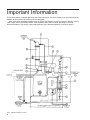
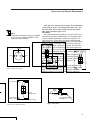
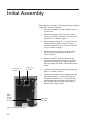
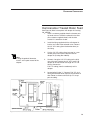
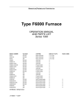
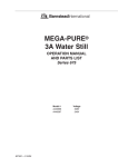
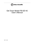
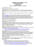
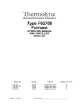
MEGA-PURE®
One Liter Water Still
OPERATION MANUAL
AND PARTS LIST
SERIES 798
Model Number
A440266
A440267
A7981
A7982
LT798X1 • 7/31/02
Voltage
120V
120V
240V
240V
Without Bottle
With Bottle
Without Bottle
With Bottle
Important Information
This manual contains important operating and safety information. You must carefully read and understand the
contents of this manual prior to the use of this equipment.
Water purification technology employes one or more of the following: chemicals, electrical devices, mercury
vapor lamps, steam and heated vessels. Care should be taken when installing, operating or servicing
Barnstead products. The specific safety notes pertinent to this Barnstead product are listed on page 4.
Figure 1 MEGA-PURE One Liter Still
2
Table of Contents
Important Information....................................................................................................................................2
Table of Contents..........................................................................................................................................3
Safety Information ........................................................................................................................................4
Alert Boxes ............................................................................................................................................4
Warnings ................................................................................................................................................4
Introduction ..................................................................................................................................................6
Unpacking ....................................................................................................................................................7
Installation and Service Requirements ........................................................................................................8
Location of Unit ......................................................................................................................................8
Service Requirements ............................................................................................................................8
Power ....................................................................................................................................................9
Water Supply Requirements ..................................................................................................................9
Drain ....................................................................................................................................................10
Initial Assembly ..........................................................................................................................................10
Feedwater Connections ..............................................................................................................................11
Tap Water Boiler Feed..........................................................................................................................11
Pretreated Boiler Feed ........................................................................................................................12
Demineralizer Treated Boiler Feed ....................................................................................................13
In-House Treated Boiler Feed ............................................................................................................14
Still Output Connections ............................................................................................................................16
Storage Bottle Installation ....................................................................................................................16
Automatic Collection System Installation ............................................................................................17
Operation ....................................................................................................................................................18
High Temperature Cut-off Switch ........................................................................................................19
Maintenance and Servicing ........................................................................................................................20
Cleaning ..............................................................................................................................................20
Troubleshooting....................................................................................................................................21
General ................................................................................................................................................21
Electrical ..............................................................................................................................................23
Still Troubleshooting ............................................................................................................................23
Automatic Collection System Troubleshooting ....................................................................................24
Parts List ....................................................................................................................................................25
Parts arranged by Exploded View key number....................................................................................25
Exploded View ............................................................................................................................................26
Wiring Diagram ..........................................................................................................................................27
Ordering Procedures ..................................................................................................................................28
One Year Limited Warranty ........................................................................................................................32
3
Safety Information
Your Barnstead MEGA-PURE One Liter Water Still has been
designed with function, reliability, and safety in mind. It is your
responsibility to install it in conformance with local electrical
codes. For safe operation, please pay attention to the alert
signals throughout the manual.
Alert Signals
Warning
Warnings alert you to a possibility of
personal injury.
Warnings
To avoid electrical shock, always:
1. Use a properly grounded electrical outlet of correct
voltage and current handling capacity.
2.
Ensure that the equipment is connected to electrical service according to local and national standards. Failure to properly connect may create a
fire or shock hazard.
3.
Do not mount the MEGA-PURE One Liter Water
Still directly over equipment that requires electrical
service. Routine maintenance of this unit may
involve water spillage and subsequent electrical
shock hazard if improperly located.
4.
Replace fuses with those of the same type and rating.
5.
Disconnect from power supply before servicing.
6.
Do not connect unit to electrical service until
instructed to do so.
Caution
Cautions alert you to a possibility of
damage to the equipment.
Note
Notes alert you to pertinent facts
and conditions.
To avoid personal injury:
1. Do not use in the presence of flammable or combustible materials; fire or explosion may result.
This device contains components which may ignite
such materials.
4
2.
Wear eye and hand protection when using acid for
cleaning, as acid spattering may occur.
3.
Use this device with water feed only. Failure to
comply with the above could result in explosion
and personal injury.
4.
Ensure all piping connections are tight to avoid
leakage of chemicals.
SAFETY INFORMATION
5.
Always depressurize chemical lines before disassembly.
6.
To avoid exposure to chemical fumes, ensure adequate ventilation when using chemicals for cleaning.
7.
Follow carefully the manufacturers’ safety instructions on labels of chemical containers and Material
Safety Data Sheets (M.S.D.S.).
8.
“Caution - Hot Surface. Avoid Contact.” Glass portions of still become hot when still is operating. To
avoid burns, do not touch hot glass.
9.
Refer servicing to qualified personnel.
C. To ensure safe mounting:
1. Wall composition and construction, as well as fastener type, must be considered when mounting
this unit. The mounting surface and fasteners
selected must be capable of supporting a minimum
of 60 lbs.; inadequate support and/or fasteners
may result in damage to mounting surface and/or
equipment. If you are unsure of mounting surface
composition, condition and construction, or correct
fasteners, consult your building maintenance group
or contractor.
5
Introduction
Warning
Use a properly grounded electrical outlet
of correct voltage and current handling
capacity.
Ensure that the equipment is connected
to electrical service according to local
and national standards. Failure to properly connect may create a fire or shock
hazard.
Do not mount the MEGA-PURE One
Liter Water Still directly over equipment
that requires electrical service. Routine
maintenance of this unit may involve
water spillage and subsequent electrical
shock hazard if improperly located.
Do not connect unit to electrical service
until instructed to do so.
Note
Operation of the still at a voltage
less than the stated voltage will
cause a drop in still output.
6
Your Barnstead MEGA-PURE One Liter Water Still is a compact, all glass unit with Teflon® connectors designed to provide 1.4 liter per hour of high purity distilled water. The product water is non-pyrogenic per USP XIX. Resistivity will be
greater than 1.0 megohm-cm at the condenser outlet using
most tap water as feed. This water still can be used as a discrete unit or with customer supplied pretreated water. It can
also be connected to the Barnstead Automatic Collection
System for completely automatic operation.
Your MEGA-PURE One Liter Water Still allows you to
replace tap water boiler feed with demineralized, distilled or
R.O. water for low maintenance operation and high purity distillate. Distilled water storage can be easily handled in the
optional 6-liter polyethylene or 9-liter Pyrex brand storage
bottle. Either fits conveniently inside the water still cabinet
and dispenses distilled water through a valve which is accessible at the front of the still.
Choice of a location for your MEGA-PURE One Liter Water
Still is primarily a matter of convenience. This unit may be
located on a bench or wall mounted.
Your MEGA-PURE One Liter Water Still is rated at either
120 volts, 50/60 Hz, 1000 watts, single phase or 240 volts,
50/60 Hz, 1000 watts, single phase. This unit requires
approximately 11 to 15 liters per hour of cooling water.
The cabinet and glassware are protected against damage
from overheating by a thermal switch.
Unpacking
Tools required: Diagonal cutting pliers.
1.
Remove parts box and still from shipping carton
and place on workbench.
2.
Check glassware inside the main cabinet for
damage. Check parts in the accessory box for
damage. Identify any broken or damaged parts
and report them to your dealer immediately.
Refer to Figure 1 (page 2) for the following step:
3. Using diagonal cutting pliers, cut and remove
the five (5) plastic shipping ties. The shipping
tie locations are: Two (2) on the condenser "B",
two (2) on the boiler "I", and one (1) on the trap
"N."
7
Installation and Service
Requirements
Location of Unit
Warning
Do not mount the MEGA-PURE One
Liter Water Still directly over equipment that requires electrical service.
Routine maintenance of this unit
may involve water spillage and subsequent electrical shock hazard if
improperly located.
Wall composition and construction,
as well as fastener type, must be
considered when mounting this
unit. The mounting surface and
fasteners selected must be capable of supporting a minimum of
60 lbs.; inadequate support
and/or fasteners may result in
damage to mounting surface
and/or equipment. If you are
unsure of mounting surface composition, condition and construction, or correct fasteners, consult
your building maintenance group
or contractor.
Warning
Ensure that the equipment is connected to electrical service according to local and national standards.
Failure to properly connect may create a fire or shock hazard.
Do not connect unit to electrical service until instructed to do so.
8
Choice of location for the MEGA-PURE One Liter Water Still
is primarily a matter of convenience as long as the service
requirements, listed on the next page, are met.
A. The still may be bench or wall mounted. Allow 4"6" clearance at the sides and top for circulation of
ambient air to prevent buildup of heat in the cabinet.
B.
Unit Dimensions: 18" wide x 10" deep x 34" high.
C.
Wall Mounting: The still is supplied with slotted
mounting holes located 16" on center in the rear of
the cabinet and
22 7/8" from the bottom. The weight of the unit
with a full storage bottle is 45-60 lbs.
Service Requirements
Power
Your water still is supplied with a power cord (5 feet long) and
plug. The plug on the 120V unit requires a standard North
American 120V, 15A, 3-prong receptacle. The plug on the
240V unit requires a standard European 240 volt receptacle.
(See Figure 2.) If you do not have the required receptacle
available within 5 feet of your still, a certified electrician
should install one in accordance with local and national standards. As an alternate method of power supply for a 240 volt
unit, your electrician may remove the supplied plug and wire
the cord to a 15A-250V breaker box.
(See Figure 3.)
Water Supply Requirements
Barnstead recommends one of the following options for supplying water to operate your MEGA-PURE One Liter Water
Still.
OPTION #1
A single, untreated cold water supply. The supply must be
capable of providing a minimum of 4 gallons (15 liters) per
hour at a pressure of 20-100 psi and be located within 4 feet
(1.2 meters) of the MEGA-PURE One Liter Water Still. You
must provide a shut off valve and reducer as shown in Figure
4.
INSTALLATION AND SERVICE REQUIREMENTS
Note
The double solenoid valve kit is not needed
if you are using a MEGA-PURE D1 or D2
deionizer for pretreatment.
Ground
Line
Line
Drain
An open or atmospherically vented drain located lower than
the still is necessary to allow for gravity flow. Barnstead supplies a 5 foot length of 1/2" I.D. vinyl tubing for the drain.
Additional tubing may be purchased from your laboratory
dealer.
Figure 2 240 Volt Receptacle
Line Ground
With Option #1, approximately 4 gallons of untreated water
will be used per hour in the cooling section of the still, 1 gallon of this water will be used as boiler feed. Water connections are discussed on pages 13-14.
OPTION #2
An untreated cold water supply plus a source of RO, demineralized or previously distilled water. The untreated supply
must be capable of providing a minimum of 4 gallons (15
liters) per hour at a pressure of 20-100 psi and be located
within 4 feet (1.2 meters) of the water still. The treated supply
must be capable of providing 1 gallon (3.75 liters) per hour
and be located within 4 feet of the water still. You must provide a shut-off valve and reducer at each water supply (see
Figure 4). In addition you will require the optional double solenoid valve kit (Catalog No. RY798X2A (120V) or 440236
(240V)).
With Option #2, approximately 4 gallons of untreated water
will be used each hour for cooling. The second (treated)
water supply of 1 gallon per hour will be used as boiler feed.
Water connections are discussed on pages 14-18.
Line
Water
Supply
Load
(Brown Wire)
Reducer
Load Ground
(Green Wire)
Figure 3 15A - 250V Breaker Box
Load
(Blue Wire)
2"-3"Lengthofpipe
with
1/8"
N.P.T.
Figure 4 Shut-offValve
9
Initial Assembly
Tools required for assembly: 7/16" open end wrench, diagonal
cutting pliers, common screwdriver.
1. Unwrap the condenser “B” and thoroughly flush all
of the salt out.
Solenoid Power
Receptacle
Heater Power
Receptacle
MEGAPURE
Deionizer
Control
Receptacle
Figure 5 Control Bottom Connections
10
2.
Reattach the condenser “B” to the still and then
attach the two Teflon connectors “D” and “P” to the
condenser “B” as shown in Figure 1.
3.
Check orientation of trap "N." If it is not level or tilted back toward the boiler as shown in Figure 1,
move the condenser "B" up in its bracket. This will
tilt trap as shown in Figure 1.
4.
Remove the packing material and rotate tube "L"
into the constant level chamber of boiler "I" as
shown in Figure 1.
5.
Unpack the Vycor® immersion heater "M" and
check the voltage rating on the top cap. It should
agree with the voltage of your power supply. If it
does not, contact your dealer and order the correct
heater.
6.
Insert the immersion heater into the top opening of
boiler "I" as shown in Figure 1.
7.
Thread the heater plug and cord through the large
hole above the boiler "I," then back through the
hole below the control box "H." Plug heater plug
into the receptacle on the bottom of the control
box. The plug is twist-lock type and requires 1/4
clockwise turn to lock in place.
ACS Control
Receptacle
Feedwater Connections
Note
Barnstead strongly recommends that
you install the optional flowmeter
(Catalog Number 440092) into your
feedwater line(s). This will allow you
to control the flow of water to your
still easily and precisely.
This still always uses tap water for cooling the steam in the
condenser. However, you have the option of feeding your
boiler with higher purity pretreated water, thereby reducing
the need to drain and clean your boiler.
If you will be using tap water as your boiler feedwater, proceed to the Tap Water Boiler Feed section. If you will be
using a supply of distilled, deionized or reverse osmosis
water as your boiler feed, proceed to the Pretreated Boiler
Feed section.
Tap Water Boiler Feed
See Figure 6
1. Install a customer supplied shutoff valve onto your
tap water source. Thread the solenoid valve onto
your customer supplied shutoff, with the side
marked “in" toward the shutoff.
2.
Install the supplied fitting to the “out” side of the
solenoid valve. Connect the 5/16" I.D. tubing (from
the condenser) to this fitting.
3.
Route 3/8" I.D. vinyl drain tubing to an atmospherically vented drain.
Figure 6 Tap Water Feed Only
11
FEEDWATER CONNECTIONS
4.
Plug the solenoid valve power cord (not shown)
into the receptacle on the bottom of the control box
"H." (See Figure 5.)
5.
Go to the Still Output Connections section to complete your still's setup.
Pretreated Boiler Feed
When a supply of distilled, deionized or reverse osmosis
water is to be used as boiler feed, first revise the still connections as follows:
1. Remove boiler fill tube "O" from still and set aside.
2.
Locate the 3/8" I.D. x 44" long vinyl tubing and one
barbed tee (3/8" I.D. x 3/8" I.D. x 3/8" I.D.) in the
parts box.
3.
Install one end of the vinyl tubing to the cooling
water outlet located on the top right of the condenser "B" (where boiler fill tube "O" was
attached). Route the other end through the cabinet
and down the back as shown in Figure 7.
4.
Cut the 3/8" I.D. vinyl drain tubing and install the
barbed tee. Connect the 3/8" I.D. vinyl tubing from
condenser to the barbed tee. Push the vinyl tubing
all the way onto the tee to assure a leak free seal.
5.
Route the drain tubing to an atmospherically vented drain.
If you will be using a MEGA-PURE D1 or D2 demineralizer to
provide pretreated boiler feed, go to the Demineralizer
Treated Boiler Feed section. If you will be using an "in-house"
source of pretreated water for boiler feed, go to the In-House
Treated Boiler Feed section.
Figure 7 Tubing Connections
12
FEEDWATER CONNECTIONS
Demineralizer Treated Boiler Feed
See Figure 8. (Must have optional still adapter kit: Catalog
No. 440376)
1. Install a customer supplied shutoff valve onto your
tap water source. Thread the solenoid valve onto
your customer supplied shutoff, with the side
marked “in" toward the shutoff.
Note
If using the optional flowmeter,
install it at this point instead of the
adapter.
2.
Install the fitting supplied with the still adapter kit
into the “out” side of the solenoid valve. Connect
the 1/4" O.D. tubing (from the demineralizer) to
this fitting.
3.
Cut the 1/4" O.D. tubing (from last step) at a convenient point and install the tee from the still
adapter kit (Catalog No. 440376).
4.
Connect a length of 1/4" O.D. tubing to the third
arm of the tee. Connect the 1/4" O.D. to 3/8" I.D.
adapter to the free end of this length of 1/4" O.D.
tubing. Connect the
5/16" I.D. tubing (from the condenser) to this
adapter.
5.
Locate boiler fill tube "L." Connect 7/16" I.D. vinyl
tubing from demineralizer output to end of boiler fill
tube. Route as shown and install clip "S" to support the tubing.
Figure 8 Deionizer Feed
13
FEEDWATER CONNECTIONS
6.
Route 3/8" I.D. vinyl drain tubing to atmospherically vented drain.
7.
Plug solenoid valve power cord (not shown) into
receptacle in control box "H."
8.
Plug still adapter kit cable into right side of demineralizer and receptacle in control box "H."
9.
Go to the Still Output Connections section on page
19 to complete the setup of your still.
In-House Treated Boiler Feed
See Figure 9. (Must have optional double solenoid valves:
Catalog No. 440236 (240V), RY798X2A (120V))
1. Install customer supplied shutoff valves onto your
tap water source and your in-house treated water
source. Thread the solenoid valves onto your customer supplied shutoffs, with the sides marked “in"
toward the shutoffs.
2.
Figure 9 In-house Treated Feed
14
Install the supplied 5/16" fitting to the “out” side of
the solenoid valve on your tap water source.
Connect the 5/16" I.D. tubing (from the condenser)
to this fitting.
FEEDWATER CONNECTIONS
3.
Connect the 3/8" fitting and 3/8" I.D. vinyl tubing
from the double solenoid valve kit to the “out” side
of the solenoid valve on your treated water supply.
4.
Locate the boiler fill tube "L." Connect 3/8" I.D.
from treated water supply solenoid to the end of
the boiler fill tube. Route as shown and install clip
"S" to support the tubing.
5.
Route the 3/8" I.D. vinyl drain tubing to an atmospherically vented drain.
6.
Plug the solenoid valve power cord (not shown)
into the receptacle in control box "H" (See Figure
5.)
7.
Go to the Still Output Connections section on page
19 to complete the setup of your still.
15
Still Output Connections
If you are using one of the optional Storage Bottles, go to the
Storage Bottle Installation section. If you are connecting your
still to an Automatic Collection System, go to the Automatic
Collection System Installation section.
Note
The storage bottles do not automatically control the still.
Figure 10 Storage Bottle Installation
16
Storage Bottle Installation
To install the optional 6 or 9 liter storage bottle inside the one
liter still cabinet, first locate the following parts in the storage
bottle parts box:
Product delivery tube "F"
Teflon Connector "E"
20" length of 1/2" vinyl tubing
Plastic tee (1/2 X 1/2 X 1/2)
1.
Place storage bottle (with product delivery tube "F"
installed) inside still cabinet below condenser "B."
Connect product delivery tube to condenser with
Teflon connector "E."
2.
Locate plastic tee (1/2 x 1/2 X 1/2) and 20" length
of 1/2" vinyl tubing in parts box. Connect to bottle
overflow tubulation and drain as shown in Figure
10 below.
STILL OUTPUT CONNECTIONS
Automatic Collection System
Installation
Before connecting your MEGA-PURE One Liter Water Still to
the Barnstead Automatic Collection System, move the still to
its final location.
1. Locate ACS tube "Q" and Teflon connector "E" in
the ACS parts box. Locate distillate outlet tube
(TU798X1) in the still parts box. Assemble to tubing from collection system as shown in Figure 11.
2.
Plug input jack from ACS into ACS receptacle on
bottom of still control box "H." (See Figure 5)
Figure 11 Complete System Layout (Not to scale)
17
Operation
Warning
Use a properly grounded electrical
outlet of correct voltage and current
handling capacity.
Ensure that the equipment is connected to electrical service according to local and national standards.
Failure to properly connect may create a fire or shock hazard.
Do not use in the presence of flammable or combustible materials; fire
or explosion may result. This device
contains components which may
ignite such materials.
Plug electrical power cord into appropriate receptacle.
Refer to Figure 1, page 2 for referenced locations.
1. Close drain clamp "G" on bottom of boiler "I."
2.
Open valve at tap water source and treated water
source if so installed.
3.
Switch on the main power breaker on control at
customer power source.
4.
Push “Water” switch on control box "H". Green
indicator will light and solenoid will open. Allow
boiler to fill.
5.
Push “OPERATE” switch. Indicator will light and
heaters will come on.
6.
Allow the still to operate for 15-20 minutes. For
maximum volume of distillate, increase the flow of
cooling water to the point where only a slight wisp
of steam is visible at the condenser vent "A." If you
are using a separate source of pretreated water for
your boiler feed, adjust the boiler feed flow so that
a constant overflow from the boiler is maintained.
7.
Your MEGA-PURE One Liter Water Still should
now be operational. Run the still for 4-5 hours to
cleanse itself before collecting water for use.
8.
To shut your water still off push the OFF switch.
This will shut the water supply and the heaters off.
Use this device with water feed only.
Failure to comply with the above
could result in explosion and personal injury.
“Caution - Hot Surface. Avoid
Contact.” Glass portions of still
become hot when still is operating.
To avoid burns, do not touch hot
glass.
If any difficulties are encountered in operating this water still,
check all operating and assembly steps to be sure the still
was assembled and is being operated correctly. If the difficulty still exists, consult the Troubleshooting section of this manual.
18
OPERATION
Note
If you are feeding an ACS with your
still, note that when the ACS is full, it
will signal the still to shut down.
During this shut-down, the heater
and the water supply will both shut
off and the front panel lights on the
still will be extinguished. This normal
operation can mimic the effects of
an overheating boiler, but does not
represent any problem with the still.
High Temperature Cut-off Switch
Your MEGA-PURE One Liter Water Still is protected against
overheating by a thermal switch located in the control box at
the right hand side of the boiler. Should the boiler overheat,
the switch will open causing the heater and water supply to
shut off. When the boiler cools (5-15 minutes), the switch will
reset automatically, but the still will have to be restarted by
the operator. When unit has cooled, press the “WATER”
switch and then the “OPERATE” switch to restore normal
operation. Check boiler occasionally for proper water level.
19
Maintenance and Servicing
Warning
Disconnect from the power supply
before servicing.
Wear eye and hand protection when
using acid for cleaning, as acid spattering may occur.
Ensure all piping connections are
tight to avoid leakage of chemicals.
Always depressurize chemical lines
before disassembly.
Cleaning
For top performance and efficiency, the MEGA-PURE One
Liter Water Still should be kept clean and free of scale. It is
recommended that the boiler be drained and refilled with
fresh water daily to flush the boiler of the concentration of
contaminants from the previous day’s run.
When using untreated boiler feed, cleaning is recommended after every 15-20 hours of operation. The unit should be
cleaned with a hydrochloric acid solution. This is done as follows:
1. Push unit “OFF” switch.
2.
Disconnect output tubing at condenser "B" from
collection vessel and temporarily place a beaker
under condenser outlet.
3.
Drain boiler by opening clamp "G." Close clamp
"G" after boiler has completely drained. Refill boiler.
4.
Use the spare pinch clamp from the parts box to
shut off overflow tube from constant level chamber
"K" as close as possible to overflow stem.
5.
Carefully pour approximately 260 ml. of 10%
hydrochloric acid solution into top of constant level
chamber "K."
6.
Wait approximately 10 minutes or until residue disappears. If additional cleaning is required, drain
boiler down 1 inch and turn unit on for a few minutes until residue disappears. Do not boil. Turn the
still off.
7.
Carefully drain the unit, remove clamp from overflow tube and refill with fresh water. Drain boiler,
refill with fresh water and operate for 30 minutes.
Reconnect tubing from collection vessel to condenser "B."
To avoid lung injury or suffocation,
ensure adequate ventilation when
using chemicals for cleaning.
Follow carefully the manufacturers’
safety instructions on labels of
chemical containers and Material
Safety Data Sheets (M.S.D.S.).
Refer servicing to qualified personnel.
20
MAINTENANCE AND SERVICING
Troubleshooting
General
Problem
Leaks.
Rough Boiling.
Scale Build-up.
Heater Failure.
Heater failure due to scale
build-up or alkali attack will
not be replaced under
warranty.
Causes
The most common leak is one
occurring in the vinyl drain
tubing. Hot water causes
softening and pulling loose at
the plastic barbed connectors.
Rough boiling is the result of
alkali attack to the matte finish
on the heaters. The most
common cause is using water
pretreated with NaCI
regenerated water softeners.
A brownish-white scale in the
boiler indicates that the boiler
requires cleaning.
Solution
Runs of vinyl tubing should be
supported to reduce the pull
on the plastic connectors.
Small clamps may be used to
firmly hold the vinyl tubing.
Remove heater and lightly
roughen surface with 150 grit
sandpaper.
Clean boiler per cleaning
instructions. Scale should not
be allowed to accumulate as
heaters may be damaged.
Short life on Vycor®
immersion heaters can usually
be attributed to use of water
pretreated with NaCI
regenerated water softeners
or excessive scale buildup.
Softened water used as a
boiler feed causes a
concentration of sodium ions
and alkaline attack of the
Vycor® glass. Rough boiling
will be the first indication of
alkaline attack. At failure, the
heaters will usually pinhole
and water entering will short
out the element.
If softened water must be
used, heater life can be
prolonged somewhat by
draining boiler every day.
Scale build-up will occur when
boiler feed is not being
deionized.
When using the still without a
deionizer, scale build-up must
be removed after every 15-20
hours of operation (see
"Cleaning Instructions").
Failure to do so will cause
heaters to build up heat
internally and fail or cause
glass envelope failure.
21
MAINTENANCE AND SERVICING
General (con't)
Problem
Steam at Condenser Vent.
Causes
A slight wisp of steam exiting
at the condenser vent is
normal. Gases in the steam are
also being removed.
No Steam at Condenser Vent.
Water Pressure Variations.
Output Less Than 1 Liter/Hr.
Pressure fluctuations in your
tap water line will cause erratic
flow in cooling water and may
cause water level in boiler to
drop.
Heaters will produce in excess
of 1 L/hr. of distilled water
when run at the rated voltage.
At lower voltages, output will
drop accordingly.
Also see "Steam at
Condenser Vent" as excess
steam at this point will reduce
output.
22
Solution
If there is an excessive amount
of steam leaving the
condenser vent, increase the
cooling water flow rate.
If no steam is visible, decrease
cooling water flow rate.
Have a plumber install a
pressure regulator in your tap
water line and regulate to 2025 psi.
OPERATION
Electrical
Before troubleshooting can begin, the problem component must be determined. That is accomplished as follows:
1. Disconnect the demineralizer and ACS jacks from the still control box and attempt to run the still. If still
fails, see “Still Troubleshooting.” If still runs, go to step #2.
2.
Connect the demineralizer input jack back up to the still control box and attempt to run the still. If still
fails to run see “Demineralizer Troubleshooting” (in the Demineralizer Manual). If still runs, see
“Automatic Collection System Troubleshooting.”
Still Troubleshooting
Problem
Heaters and water will not stay
on.
Heater not boiling, heater light
on.
Cause
Hi-temp cut-off switch open.
Heater not working.
Water will not come on, but
light works.
No lights in switches.
Heater element burnt out.
Solenoid valve not working.
Heater element burnt out.
ACS full; still off.
Indicator lights burnt out.
Fuse(s) blown.
Heater shorted.
Solution
Remove control box and
replace switch.
Check heater (13.9Ω for 120V
or 55.9Ω for 240V) and
replace.
Replace heater.
Check plug for connection.
Replace solenoid valve.
This is normal operation when
the still is used to feed an
ACS. When water level in the
ACS dropps, still will reactivate
and lights will come back on
automatically.
Replace switches (switches
will operate without lights).
Check heater (13.9Ω for 120V
or 55.9Ω for 240V) and
replace.
High voltage.
Unit off, but water still flowing.
Solenoid valve installed
backwards.
Check input voltage against
heater rating. Correct.
Solenoid labeled "in" on input
side. Check.
Solenoid valve stuck open.
Replace solenoid valve.
23
MAINTENANCE AND SERVICING
Warning
Replace fuses with those of the same type and rating.
Automatic Collection System Troubleshooting
Problem
Will not turn still on or off as it
should.
24
Cause
Float stuck.
Solution
Remove level control cover
and free-up.
Switch not working.
Replace switch.
Input jack not plugged in.
Check and reconnect.
Jack board defective.
Replace jack board.
Parts List
All replacement parts must be ordered through your laboratory dealer.
Parts arranged by Exploded View key number
Exploded View
Key Number
1
2
3
4
5
6
7
8
9
10
11
12
13
14
15
16
17
Figure 1 Item Key
A
C
B
P
D
N
O
L
I
G
H
F
J
M
M
Q
Not Shown
Not Shown
Not Shown
Not Shown
Not Shown
Optional Accessories
18
18
Description
Steam Vent Tubing
Boiler/Condenser Spring (set of 4)
Condenser
Teflon® Connector (3/8" I.D.)
Inlet Tubing
Teflon® Connector (1 5/32" I.D.)
Steam Trap
Boiler Fill Tube (Cond. to Conn.)
Teflon® Connector (3/8" I.D.)
Boiler Fill Tube (Conn. to Boiler)
Boiler
Constant Level Overflow Tubing
Boiler Drain Tubing Clamp
Boiler Drain Tubing
Drain "T"
Drain Tubing
Electrical Control Box (120V)
Electrical Control Box (240V)
Distillate Outlet Tube - Tubing/Bottle
Water, Operate, Off Switches
Vycor Immersion Heater, 120V-1000W
Vycor Immersion Heater, 240V-1000W
Distillate Outlet Tube - ACS
Electrical Control Box PC Board
Solenoid Valve (120V)*
Solenoid Valve (240V)
Fuse (Buss Type ABC-12A, 250V)
Hi-Temperature Cutoff Switch
6-Liter Polyethylene Bottle
9-Liter Pyrex Brand Bottle
Flowmeter Kit
Dual Solenoid Valve (120V)
Dual Solenoid Valve (240V)
19
Connector** within electrical box
*RY798X1A Solenoid Valve ( supplied with still)
**CE798X1A #19 is shown in Figure 5
Part Number
TU674X6
416104
401203
401398
TU674X7
401397
401202
401215
401398
401216
401201
TU674X3
927917
TU674X2
927326
TU674X1
CN798X1A
CN798X2A
TU798X2
SW745X1A
740880
EL798X1B
TU798X1
PC798X1A
RY798X1A
440093
410148
SWX150
413964
410535
440092
RY798X2A
440236
CE798X1A
25
Exploded View
26
Wiring Diagram
27
27
Ordering Procedures
Please refer to the Specification Plate for the complete model number, serial number, and series
number when requesting service, replacement parts or in any correspondence concerning this
unit.
All parts listed herein may be ordered from the Barnstead International dealer from whom
you purchased this unit or can be obtained promptly from the factory. When service or replacement parts are needed we ask that you check first with your dealer. If the dealer cannot handle
your request, then contact our Customer Service Department at 563-556-2241 or 800-553-0039.
Prior to returning any materials to Barnstead International, please contact our Customer
Service Department for a “Return Goods Authorization” number (RGA). Material returned without
a RGA number will be refused.
Teflon is a registered trademark of the DuPont Company
PYREX is a registered trademark of Corning, Inc.
MEGA-PURE is a registered trademark of Barnstead International
28
29
30
31
One Year Limited Warranty
Barnstead International (“BARNSTEAD”) warrants that if a product manufactured by Barnstead shall be free of
defects in materials and workmanship for one (1) year from the first to occur of (i) the date the product is sold by
BARNSTEAD or (ii) the date the product is purchased by the original retail customer (the “Commencement
Date”). Except as expressly stated above, BARNSTEAD MAKES NO OTHER WARRANTY, EXPRESSED OR
IMPLIED, WITH RESPECT TO THE PRODUCTS AND EXPRESSLY DISCLAIMS ANY AND ALL WARRANTIES,
INCLUDING BUT NOT LIMITED TO, WARRANTIES OF DESIGN, MERCHANT ABILITY AND FITNESS FOR A
PARTICULAR PURPOSE.
An authorized representative of BARNSTEAD must perform all warranty inspections. In the event of a defect
covered by BARNSTEAD’s warranty, BARNSTEAD shall, as its sole obligation and exclusive remedy, provide free
replacement parts to remedy the defective product. In addition, for products sold by BARNSTEAD within the continental United States or Canada, BARNSTEAD shall provide provide free labor to repair the products with the
replacement parts, but only for a period of ninety (90) days from the Commencement Date.
BARNSTEAD’s warranty provided hereunder shall be null and void and without further force or effect if there is
any (i) repair made to the product by a party other than BARNSTEAD or its duly authorized service representative, (ii) misuse (including use inconsistent with written operating instructions for the product), mishandling, contamination, overheating, modification or alteration of the product by any customer or third party or (iii) use of
replacement parts that are obtained from a party who is not an authorized dealer of BARNSTEAD.
Heating elements, because of their susceptibility to overheating and contamination, must be returned to the
BARNSTEAD factory and if, upon inspection, it is concluded that failure is due to factors other than excessive
high temperature or contamination, BARNSTEAD will provide warranty replacement. As a condition to the return
of any product, or any constituent part thereof, to BARNSTEAD’s factory, it shall be sent prepaid and a prior written authorization from BARNSTEAD assigning a Return Goods Number to the product or part shall be obtained.
IN NO EVENT SHALL BARNSTEAD BE LIABLE TO ANY PARTY FOR ANY DIRECT, INDIRECT, SPECIAL, INCIDENTAL, OR CONSEQUENTIAL DAMAGES, OR FOR ANY DAMAGES RESULTING FROM LOSS OF USE OR
PROFITS, ANTICIPATED OR OTHERWISE, ARISING OUT OF OR IN CONNECTION WITH THE SALE, USE
OR PERFORMANCE OF ANY PRODUCTS, WHETHER SUCH CLAIM IS BASED ON CONTRACT, TORT
(INCLUDING NEGLIGENCE), ANY THEORY OF STRICT LIABILITY OR REGULATORY ACTION.
The name of the authorized Barnstead International dealer nearest you may be obtained by calling 1-800-4466060 (563-556-2241) or writing to:
2555 Kerper Boulevard
P.O. Box 797
Dubuque, Iowa 52001-0797
Phone: 563-556-2241 or 800-553-0039
Fax: 563-589-0516
E-mail: [email protected]
www.barnstead.com