1
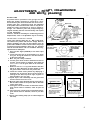
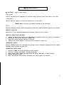
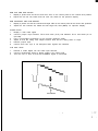
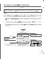
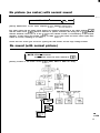
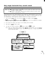
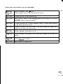
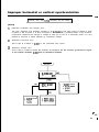
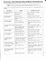
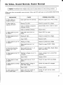
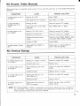
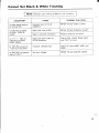
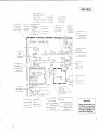
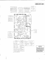
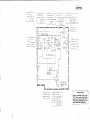
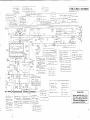
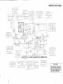
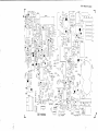
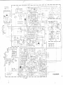
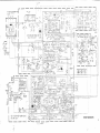
SERVICE MANUAL
MODEL 1701/1 702 MONITOR
ADJUSTMENTS - PI
AND WHIT
PICTURE TUBE
The picture tube is a precision in-line gun type. For this
picture tube, dynamic convergence is carried out by a precision deflection yoke which eliminates the use of a convergence yoke and a convergence circuit. The adjustment
of the picture tube is therefore made easier as only the adjustment of static convergence by using a magnet is
enough. The deflection yoke and purity/convergency
magnets assembly has been set at the factory and requires
no field adjustments.
However, should the assembly be accidentally jarred or
tampered with, some or all adjustment may be necessary.
COLOR PURITY & VERTICAL CENTER
Loosen yoke retaining clamp (Fig. 2-l ). With a sharp knife,
cut between the picture tube and the wedge. Remove
wedges completely and clean off dried adhesive from the
picture tube. PAINT is used to lock the tabs of the purity/
convergence magnet assembly in place (Fig. 2-I). The paint
must be removed with the end of a screwdriver before any
adjustments are attempted.
1. Inject a Video Signal (RASTER) to the Video input
terminal.
2. Let the purity tabs come in line horizontally as is shown
in Fig. 2-3. A long tab should be in the same direction
as the other short tab.
3 Move the yoke slowly backward.
4. Turn the green cut-off control to maximum and the red
and blue cut-off controls to minimum. Then adjust the
screen control so that the green band can be seen best.
(Fig. 2-4)
e direction with them
5 Rotate the two tabs in the opposite
kept at an angle. Move them in either direction so that
the green band is centered on the picture tube.
6. Check the vertical center position by displaying a
horizontal line. If incorrect, bring it to the center by
rotating the two tabs, kept at an angle, together in
either direction. (Fig. 2-5, 2-6)
7. Repeat steps 5 and 6 alternately until the green band
and the vertical centre are in line.
8. Move the yoke slowly towards the bell of the tube so
that the whole surface of the picture tube is filled with
a pure green raster.
9. Turning the red cut-off control to maximum and the
green cut-off control to minimum, check for pure red
raster.
10. Turning the blue cut-off control to maximum and the
green cut-off control to minimum, check for pure blue
raster.
1 1. Secure yoke retaining clamp (do not install wedges at
this time).
ITY, CON VERGENCE
3ALANC
.
/=I
<WEDGE
,DEF. YOKE
RETAINING CLAMP
FOUR POLES
LOCKING RING PURITY
MAGNETS (mark “P”)
Fig. 2-1
(REAR VIEW)
SHORT AND LONG
LONG AND SHORT
PROTRUSIONS
Let the protrusions come in line
Fig. 2-3
BA
(FRONT VIEW)
ND
CENTRE
Bring the green band to the centre.
(FRONT VIEW)
I
Bring the horizontal line
nearest to the white
notches shown in the
dotted circles.
Fig. 2-5
1
Fig. 2-4
(TOP VIEW)
Select the cut-off service
switch from N to S, and a
horizontal line will appear.
Fig. 2-6
4
(FRONT VIEW)
STATIC CONVERGENCE & DYNAMIC CONVERGENCE
Static convergence is achieved by four magnets located
on the neck, nearest the base of the picture tube. The front
pair of magnetic rings (closest to the purity tabs) are adjusted to converge the red and blue crosshatch lines.
The rear pair of convergence rings (closest to the base of
the picture tube) are adjusted to converge the magenta
(Red/Blue) and green crosshatch lines.
Dynamic convergence is achieved by tilting the deflection
yoke, Up-Down and Left-Right.
1. Inject Video Signal (CROSSHATCH) to the Video input terminal and adjust BRIGHTNESS and CONTRAST
control for distinct pattern.
2. Adjust the convergence around the edges of the picture tube tilting the yoke, up-down and left-right.
Temporarily install one wedge at the top of the yoke.
(Fig. 2-9, 2-l 0, 2-l 1)
3. Rotate the front pair of tabs as a unit to minimize the
separation of the red and blue lines around the center
of the screen. To adjust the convergence of red and
blue, vary the angle between the tabs.
4. Rotate the rear pair of tabs as a unit to minimize the
separation of the magenta and green lines. (Fig. 2-8)
5. Adjust the spacing of the rear tabs to converge the
magenta and green lines.
6. Apply paint to fix 6 magnets.
7. Remove the wedge installed temporarily on the yoke.
8. Tilting the angle of the yoke up, down and sideways,
adjust the yoke so as to obtain the circumference
convergence. (Fig. 2-10, 2-l 1)
9. Insert three wedges to the positions as shown in Fig.
2-l 2 to obtain the best circumference convergence.
10. Secure wedges in position with the adhesive backing
provided or use a non-conductive silicon/rubber
compound.
11. White balance adjustment (Black & White tracking) can
now be performed.
(FRONT VIEW)
I
1
Fig. 2-7
Fig. 2-8
(REAR VIEW)
l--is/ WEDGE
0)
\
DEF. YOKE
Fig. 2-9
(FRONT VIEW)
Tilting the yoke upward will move the lines
as shown with the arrows.
Fig. 2-10
(FRONT VIEW)
WHITE BALANCE ADJUSTMENT
(Black and White Tracking)
1. Inject a Video Signal (RASTER) to the Video input
terminal.
2. Set the red and green drive controls for their
mechanical center.
3. Turn the red, green and blue cut off controls and the
screen control fully counterclockwise.
4. Change the service switch as shown in Fig. 2-6, to
the “S” position.
5. Turn screen control slowly clockwise until a very faint
horizontal line appears.
6. Turn the cut off control of the color which has appeared first, clockwise by about 10° and then adjust
the screen control again so that the color may shine
faintly.
7. Turn the other color cut off controls slowly clockwise
until a reasonable white line appears.
8. Return the service switch to normal (N) position. (Fig.
2-6)
9. Adjust the red and green drive controls for best white
highlights.
Tilting the yoke upward will move the
lines as shown with the arrows.
Fig. 2-11
(REAR VIEW)
ANODE CAP
Fig. 2-12
5
NOTE: 1702 locations in (
).
Bl VOLTAGE - inject a video signal
1701 (11OV)
Regulate VR, R109, for B, adjustment so that D C voltage between TP-91 and earth is 110 volts.
1702 (125V.)
Confirm that the voltage at TP-94 and IC901 pin 4 is 125 volts.
NOTE: Meter should be periodically calibrated at 20K ohms/volt.
FOCUS
Adjust the FOCUS control for best overall definition and picture detail at normal brightness and contrast.
VERTICAL POSITION
Adjust the V. center VR R428 (R429) to the optimum vertical picture position.
VERTICAL HEIGHT AND LINEARITY
1.
2.
3.
4.
Display a pattern which allows easy
Reduce the vertical size with the V.
Adjust the vertical linearity with the
Readjust the vertical height, so that
confirmation of symmetry (such as a circle or crosshatch).
HEIGHT VR.
V. LIN. VR.
the picture extends to normal size.
HORIZONTAL WIDTH
Adjust H. WIDTH control coil L503 (L522) by turning it with a hexagonal adjusting bar only if RIGHT
and LEFT sides of picture can’t be seen.
HORIZONTAL OSCILLATOR
1.
2.
3.
4.
5.
Set the H. FREQ. VR to the mechanical center position.
Connect a jumper clip between TP-33A and TP-33B.
While rotating the H. FREQ. VR, R504, keep the picture stationary or slowly moving.
Remove the jumper wire.
Make sure that the set maintains horizontal sync, when signals are switched.
6
SUB TINT AND SUB COLOR
1.
2.
Display a picture and set the tint and color VRs on the control panel to the central click position.
Adjust the sub tint VR, R305 and sub color VR, R303 for the optimum display.
SUB CONTRAST AND SUB BRIGHT
1.
2.
Display a picture and set the contrast and bright VRs on the control panel to the center click positions.
Adjust the sub contrast VR, R209 and sub bright VR, R22 (R863) for optimum display.
COLOR SYNC
1.
2.
3.
4.
5.
6.
Display a color video signal.
Connect jumper clips between TP-40 and earth (TP-E) and between TP-51 and IC301 pin 15
(TP-51B).
Use a non-metallic screwdriver to turn trimmer capacitor C308.
Adjust so that the rolling color stripes become thick and the rolling slows or stops.
Remove jumper clips.
Confirm that color sync is not disrupted when signals are switched.
3.58 MHz TRAP
1.
2.
3.
Receive a Video Signal into the Video input terminal.
Connect oscilloscope probe to DL201 (Delay Line) output side.
Turn the core of T201 so that that 3.58MHz signal is minimized.
I
MINIMUM
TROUBLESHOOTING GUIDE
_. . -
No raster, no sound (BI is. normal)
I--- ~ NOTE: 1702 locations in (
1.
I
[Cause] Horizontal deflection circuit
Problems in the horizontal deflection circuit hinder generation of high focusing voltage, B H 16OV and
82 12V, resulting in no raster, no sound.
1.
As long as normal B H 160V is generated, the horizontal output circuit properly operates, producing pulses during the flyback period of the saw-tooth wave current passing through the horizontal deflection coil. If a problem is found with normal B H voltage, the problem area should be the
secondary coil of the flyback transformer.
2.
When the AC voltage between base and emitter of the horizontal output transistor X01 (Q522)
is about 0.8V, it is supplied with input pulses. The problem is therefore in the horizontal output
circuit. When, however, X01 (05221 is shorted, this AC voltage is not indicated even if there
are input pulses at X01 (0522).
3.
AC voltage is measured between the collector and ground of X501 IQ521 1 horizontal drive as
shown. When the specified voltage is shown on the meter, the horizontal output circuit is the
problem; while, when there is no voltage indication, the trouble is in some element(s) preceding
X501 (Q521 I. Check if those transistors and ICs are damaged using a voltage measurement.
ABNORMAL
I
Check X701 (Cl5011
1
Vc, Ve at X701 (Q501)
X-Ray protector
I
II
1I NORMAL
Is normal l3H
16OV generated?
NORMAL
NO
4
Failure in T502, L504 (TOI. L523)
or high voltage module
I’
II
I
I
More than AC 50 V
Check Vc at X01 IQ5221
horizontal output transistor
ABNORMAL (Trouble in horizontal
output circuit)
Check AC voltage between base &
emitter of X01 (Q522) horizontal
output transistor
AC = 0.5V*Trouble in horizontal output circuit
11 ov
I
Check T501 (T5211 primary coil,
Check AC voltaf- h-+S-,nacollector & grou
fC52T 1 ~__:_.._.*,
lurlrvllral drive
L’
.
Il
*. -.i*.
No raster, no sound (BI is abnormal)
_. . -
NOTE
.
1. The regulator PCB assembly used in 1702 models differs from the 1701
1702 locations in (
power PCB assembly. The B1 voltage circuits should be checked beginning with IC901.
[Cause]
Abnormal Bt voltage indicates trouble in the power supply circuit. When B1 voltage is not only low
but also abnormally high, X701 (Q501) of the X-ray protector is turned on, setting the collector voltage
to 0 V. The horizontal oscillator is then disabled resulting in no raster and no sound.
1.
When D105, R105, R108, R109 are open, the base voltage of Xl01 and X102 rise to increase
Bl voltage to more than 13OV. This causes the X-ray protector to work, resulting in no raster.
2
If the base voltage drops as when R103 is open or Cl 05 is shorted, the B1 voltage is reduced
to less than 40 V. This will mostly result in no raster, no sound.
3
When the B1 voltage drops to about 70 V, because R910 is open and D105 is shorted, the screen
becomes dark and the raster size is reduced because of insufficient horizontal and vertical
amplitude.
4 YES
NO
Can BI be adjusted to 1 IO V with
BI ADJ RI09?
r--- ------------______ -I NO
YES
Misadjustment Horizontal deflection
circuit has failed when picture is
1 smaiiwithB1 = I I O V .
Rectifier including power
transformer has failed.
supply
Does the base voltage at XI01 change
pJ+&_
+ YES
Is the emitter voltage of XI02
correct?
Does the emitter voltage of XI 01
change with BI ADJ RI09?
I
NO +
YES
X101, RIO3
open
X02 has
failed
* *.-.i.
=*__
18
.
No picture (no raster) with normal sound
.
NOTE: 1702 locations are in (
1.
I
[Cause] Malfunction of the video amplifier IC201, X202 (lC201, Q201)
The video signal and the audio signal output are supplied respectively to the video amplifier IC201
and the audio circuit IC601. Sound is had but no picture; therefore, the faulty part is IC201 and its
external elements. Since pin 16 of the IC201 to the cathode of CRT is connected by a DC-coupled
amplifier, a fault raising the emitter voltage of X202 (Q201) will cause the three initial ouptut transistors to cut off, resulting in no raster.
Check also the screen grid circuit for igniting the CRT heater and the high voltage module.
No sound (with normal picture)
NOTE: 1701 - Flowchart
1702 - Audio circuit has been reduced to IC601.
[Cause] Trouble in the audio circuit IC601, X601, X603 or X604 are faulty.
NO
YES 17V at IC601
- pin 14?
NO
l
l
C608
(short)
R605 open
_
* . . . “___
..i _
19
.
Only single horizontal line, normal sound
.
NOTE: 1701 - First check if FR401 is broken or not. If this is broken, the trouble is due to short
of X401 or break of D401.
1702 - Circuits in 1702 monitor differ but the operation remains the same. Check
vertical controls/deflection circuits.
[Cause] Malfunction of the vertical deflection circuit. When the vertical deflection circuit is faulty,
saw-tooth current is not applied to the vertical deflection coil, resulting in a single horizontal line. D u r ing troubleshooting, reduce brightness contrast to prevent an ion spot on the CRT.
1.
R401 broken, C403, D402, C413 short: B2 12V is not supplied, disabling IC501.
2.
R411, R412 broken, C407 short: the voltage at IC501 pin 3 is set to zero disabling the V-amplifier
and the voltage at pin 2 is set to zero to turn off X402.
3.
R414, R415 are broken: V B of X401 is zero disabling X401 and X402.
4.
Also check if C402 is short or open.
5.
Too high VB of X402 is because of C401 short or failure in IC501 or X402.
Note: When the voltage generator fails to supply 82 12V to the secondary coil of the flyback
transformer of the horizontal output circuit due to malfunction, a single horizontal line
and no sound will result.
VB at the vertical output
- transistor X402 is nearly zero
Vc. Ve. VE of X401 and
Vc of X402 are very high
(more than 100 V)
R413 broken. C403,
D402, C407, D405 short
X402 open IC501
faulty
Vc of X401 is very high
while VB, VE of X401
and Vc of X402 are
very low
R414, R415 broken,
X402 short,
IC501 faulty
_
^ _.
. . . ..i.
20
.
E
[Faulty parts and problems other than described]
X401 open
D401 short
C408 short
Vertical amplitude small (6 - 8 cm)
R403 faulty
A single thick (ca. 5 mm) horizontal line
R404 faulty
When turning V. HOLD, a black belt IV blanking signal) appears at the center
of screen.
The whole screen is dark and flickers.
R405 faulty
A single horizontal line. A picture flashing at about 1 second interval appears
on the upper half of the screen.
R407 faulty
A picture of about 4 cm at the center of the screen. About 25 irregular lines
appear on the upper half of the screen.
R408 and
R409 faulty
Vertical amplitude small (about 15 cm)
R410 faulty
Vertical amplitude small (about 2 cm). Picture goes slightly up and down and
flickers.
_. . .-
Picture appears only on the lower half of the screen
R416 faulty
C409 open
Vertical flyback line appears.
R419 faulty
Small number of irregular lines
_
* . ..-.i_
- ___
21
.
Improper horizontal or vertical synchronization
-. .
NOTE: 1701 and 170’2 locations are the same.
[Cause]
1)
Defective horizontal and vertical sync:
The sync separator and amplifier consists of an IC(IC201). The main cause of failure is often
a failure of the IC itself. It is also necessary to be careful of a possible failure of the external
components. Because the change of voltage at each pin of the IC is extremely small, it is very
difficult to discover a failed element by measuring voltage.
2)
Defective horizontal sync:
This is due to a failure of IC501 or the horizontal AFC circuit.
3)
Defective vertical sync:
This is due to a failure of either the separator and amplifier for the vertical synchronous signal,
or the vertical oscillator IC501 and its peripheral elements.
8.8V R IC201
pin
8?
NO
l
C202 short
1-1
9V at IC201
l
C201 short
L
l
l
R201 open
C211 short
_
* . ..-.i_
-___
22
.
Monitor parts may be secured locally. JVC part numbers have been provided for your convenience. ONLY Commodore part numbers (C 314-xxx-xx) will be available from Commodore at this time.
1701 CHASSIS PARTS
JVC PART #
DESCRIPTION
LOCATION
COM PART #
* C 314916-01
DYOI
Deflection Yoke
* CJZ6 134-OOA
JO1
Pin Jack Vid In
c39227-224
JO2
Pin Jack Aud In
L21
Deg. Coil
* A39477-T
R05
Nonflammable Res. 220 ohm, 25W, + 10%
* QRF258K-22 1
* c 314917-01
so1
Power Switch
* CEX40097-002
* C 314918-01
c39227-223
EAS-1 OP225S
SPOI
Speaker
TO1
Power Transformer
* CE30074-BOA
T502
HV Module
* CJ26107-OOA
VOl
Picture Tube
* 370FVB22(E)
x01
Transistor
x02
Regulator
* c 314919-01
* c 314920-01
Sub:
* 370ESB22(E)
* 2SD869 Sub:
c 314921-01
* 2SD898
l
+ 2SC1106A
* c 314922-01
*SAFETY COMPONENTS - Use EXACT replacement ONLY.
1701 CABINET PARTS
L OCATION
DESCRIPTION
JVC PART #
COM PART #
1 701 /1702
Front Cabinet
c 314900-01
1 701/l 702
Front Cntrl Panel Door
c 314901-01
1 701 /1702
Power Button
c 314902-01
1 701
Front Model I.D. Plate
c 314903-01
1 701/l 702
RT Side Handle
c 3 14904-01
1 701 I1 702
LT Side Handle
c 3 14905-01
1 701 /1702
Rear Cabinet
C 314906-01
1 701 /1702
Rear A/V Terminal Assy
c 314907-01
1 701/1702
1 701/l 702
Top Cabinet Panel
C 314908-01
1 701
Users Manual
c 314910-01
1 701 /1702
Namplate (Logo)
c 31491 I-01
Replacement AC Cord
+ QMPl460-244K
* c 314909-01
*SAFETY COMPONENTS - Use EXACT replacement ONLY.
* *.-.i_
.-*__
23
.
TROUBLESHOOTING GUIDE - 1702
Additional inform&ion to aid in the troubleshooting of the 1702 monitor has become available
from our technical sipport group. It has be& collated into chart form and is being provided
to facilitate repairs on this model. The 1702 is the most common monitor in the field at this
time.
”
CHART TERMINOLOGY:
CHECKPOINTS
. . . . . . . . . Point of circuit to be tested
CAUSE . . . . . . . . . . . . . . . . Possible reason for INCORRECT
signal or voltage
POSSIBLE SOLUTION ....... Most likely failure
MISSING ................ Signal or voltage not present or
INCORRECT
PATH . . . . . . . . . . . . . . . . . COMPONENTS or TRACES directly
related to that portion of the circuit
being checked
TIPS:
l
l
l
l
l
l
When testing IC circuits, always check for proper BIAS and B+ voltages
on all legs of the chip.
An open horizontal oscillator or driver circuit will cause the Bl, 125 volt
line, to raise to 158 VDC. To troubleshoot this failure, use the DEAD
SET, B+ ABNORMAL Chart.
An improperly regulated Bl will cause a BLOOMING effect. Use the
DEAD SET, B+ ABNORMAL to troubleshoot this SYMPTOM.
When the horizontal oscillator is triple firing, the monitor makes a
BUZZING sound and may blow the 1A. FUSE. The horizontal/vertical
oscillator chip, IC 501, is the most common problem.
If the monitor blows the 1A. fuse, it may short out the horizontal output
transistor. A common problem is that the 2 matched diodes, D523, test
good but actually are shorted.
A wavy picture and weak video are often repaired by replacing Cl 0 1 ,
the 47OpF, 6.3V. cap.
* . ..-.i_
=w__
32
.
E
TROUBLESHOOTING GUIDE
Dead Set, B+ Abnormal
-. .
.-
NOTE: DC Voltages may be LOWEREDqdue to open ELECTROLYTIC CAPACITORS.
When more than one possible cause is given, follow each DC path back to its SCANNED RECTIFIED
SOURCE.
CHECKPOINT
Is F901 open?
POSSIBLE SOLUTION
CAUSE
(4 amp fuse)
Possible short in bridge
rectifiers.
Check for shorted diode(s) D901904, T901 or D905.
Is F902 open?
(1 amp fuse)
Possible short in high voltage
or excessive load.
Check for shorted 0522, D523 or
scan voltage source.
Is voltage at pin 1
of IC901 148 VDC?
(voltage regulator)
Possible open path from bridge
to regulator.
Check for open R902, R907, or
C904 or F902.
Is voltage at pin 2
of IC901 126 VDC?
(voltage regulator)
Possible open reference circuit.
Check for open R904, R908, R906
or C907.
Is voltage at pin 4 of
IC901 125 VDC?
(voltage regulator)
Possible open feed back path
or defective chip.
Check for open R901 or IC901.
Is voltage at positive
side of C905 18 VDC?
Possible defective bridge.
Check for open or shorted 0905.
I
If the DC fuse (902) is open and no SHORTED parts are readily apparent, then TEMPORARILY jump
it out with a 100 watt 125 volt LIGHT BULB. This will absorb MOST OF THE OVER CURRENT ON
THE (125) Bl LINE. EXTREME caution should be used in this operation, as some resistors on the
scan voltage lines may start to burn due to shorted components.
LIGHT BULB GLOWS AT 75% INTENSITY
I
Is voltage at pin 4 of
IC901 or 125 VDC?
High resistance short or short
on secondary side of Flyback.
Check Q522 for leakage CONTINUE to next line.
Is voltage on cathode
side of D422 25 VDC?
Defective diode or short on
125V line.
Check D422 for a short or open CONTINUE to next line.
Is R421 open or
BURNING?
Short in 25.8 VDC line.
Check IC421 for a short.
_
A
- ___
. ..-.i_
33
E
Dead Set, B+ Abnormal (Continued)
CHECKPOINT
CAUSE
POSSIBLE SOLUTION
Is voltage on cathode
side of D522 13 VDC?
Short on 13.8 VDC line.
.
Open legs on 13.8 volt line until
short clears.
Is voltage on cathode
side of D551 12 VDC?
Defective diode.
Check D551 for a short or open.
Short on 12.5 VDC line.
CONTINUE to next line.
Is R551 open or
BURNING?
Short on 12.5 VDC line.
Check IC601 for a short.
Is voltage on cathode
side of 0521 200 VDC?
Defective diode.
Check D521 for a short or open.
Short on 200 VDC line.
Check line for shorted parts.
NOTE: The above chart may also be used without the light bulb to isolate missing scan
voltages.
No Raster, Sound Normal, High Voltage Normal
NOTE: Make sure that the heaters in the CRT are lit before using this chart.
CHECKPOINT
CAUSE
POSSIBLE SOLUTION
Is Video signal present
at terminal C4?
Improper bias to R-G-B
amplifiers.
REFER TO NO VIDEO CHART.
Is 200 VDC at positive
side of C351?
No scan voltage.
Check D521 for open or short,
L523 for open.
Is 171 VDC at collectors
of 0351, Q352, Q353?
Open path from C351 to
R-G-B amplifiers.
Check L351, R359, R358 and R357
for open.
Is 400 VDC at pin 8
of CRT?
Missing screen voltage.
Check for open R363, HV bleeder
resistor or shorted C352.
* *.-.i_
.--_
34