1
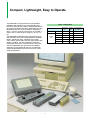
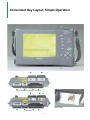
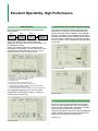
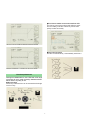
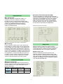
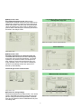
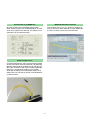
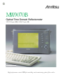
MW9070B
Optical Time Domain Reflectometer
1.31/1.55 µ m (SM), 0.85/1.3 µ m (GI)
Keyboard sold separately
High-performance mini-OTDR for installing and maintaining optical fiber cables
Compact, Lightweight, Easy to Operate
The MW9070B is a high-performance mini-OTDR for
installation and maintenance of subscriber fiber optic
lines and other fiber optic cables. It automatically detects
the positions of faults in the cable, and displays an event
table listing faults, and a trace waveform. Despite the
large 7” screen, the high-performance mini-OTDR is
just the size of a B5 file and it weighs in at only 3.2
kg.
The MW9070B is designed with a wide dynamic range
and short dead zone, and is indispensable for detecting
faults in optical trunk lines, subscriber lines, optical
CATV cables, optical LANs, and other types of fiber optic
cables. In addition, it is also invaluable in measuring
transmission line losses, connection losses, return loss
and other parameters. Six optical units are available
depending on the wavelength and type of optical fiber,
making the MW9070B an economic choice for a wide
range of applications.
Basic configuration
Models
Main frame MW9070B
Optical
units
2
Wavelength Optical
(µm)
fiber
—
—
Dynamic range
dB (SNR=1)
—
MW0970B
1.31
SM
36
MW0972B
1.31/1.55
SM
36/34
MW0972C
1.31/1.55
SM
41.5/39.5
MW0973J
0.85
GI
18
MW0975J
0.85/1.3
GI
22/22
Full Complement of Features and Functions
File storage
Data measured in the field can be stored in the internal
RAM, in a memory card, or on a 3.5” floppy disk. The
volatile internal RAM is back-up by battery. Files can be
copied from one storage medium to another.
Compact, lightweight, battery-operated
The MW9070B is the size of a B5 file (19.4 x 29 x
7.5 cm) and weights about 3.2 kg; it has a dustproof
construction suitable for outdoor use. It can be used
continuously for more than 5 hours. The 7” LCD simultaneously displays the trace waveform and event table; it
is a semi-transparent type to provide clear displays both
indoors and outdoors.
MX3607B OTDR Emulation Software
Data measured by the MW9070A/B can be downloaded
to a personal computer, analyzed in detail in the
Microsoft Windows environment, and compared with
previously-recorded waveforms using the MX3607B
OTDR Emulation Software. (For details, please refer to
the MX3607B data sheet.)
Easy operation and fully-automated measurements
In the fully-automatic mode (FULL AUTO), simply pressing the Start key sets the optimum distance range, pulse
width and averaging processing for the optical fiber
cable being measured, and automatically detects the
positions of any faults.
Furthermore, the real-time sweep function can be used
to update the waveform at 0.4 s/one sweep
(MW0970B/0972B/0972C), to confirm the status of the
connected fiber cable in real-time, so trouble from loose
connectors can be prevented in advance.
RS-232C interface
On-site data can be sent via the RS-232C interface to a
remote computer.
Ghost Fresnel reflection detection
Since the * marker can jump to twice the range of the x
marker, ghost Fresnel reflection can be detected easily.
In addition, a ghost marker is displayed at ghost Fresnel
events in the Event Table.
Event registration
File printing
Several selected files can be printed continuously.
Events (splices, far end, and breaks) in each fiber of
a multifiber optical fiber may sometimes occur at the
same position. Consequently, events in the first fiber
that are not detected at the threshold set previously
in the event table are registered on a second fiber
when using fully automatic mode. These events can
be added to the table using the event addition function and then events are set to the Fixed Mode. Next,
when the measurement fiber is changed, and the
Start key is pressed, all the target events of the second and subsequent fibers are measured
repeatedly and efficiently.
Visible LD light source (optical unit: option 05)
The optional visible LD light source enables direct visual
detection of optical leakage and faults even in the dead
zone. It is also useful for core identification in multicore fibers and blinks at contrast. intervals for simple
confirmation even with weak optical output.
System software upgrading
MW9070B system software can be upgraded using
memory cards. The software is read from a memory
card to add new functions. (For information on system
software upgrading, consult your sales representative.)
Functions for convenient on-site use
OLTS function
The MW0972C has a light source function (standard)
and a power meter function (Option 07). The total optical
loss of an optical fiber can be measured easily by using
the MW9070B as an OLTS (Optical Loss Test
Set).
Automatic optical connector connection status
check
This function checks the status of the connection
between the optical connector and the mini-OTDR.
It automatically detects whether or not there are any
problems with the connector such as dirt in the connector or a poor fit, and outputs an alarm.
Monitoring function (Option 02)
With this option, the MW9070B can be setup from an
external host to monitor an optical fiber; monitoring can
be performed at specified measurement intervals and an
alarm is generated if the measured loss exceeds the set
value.
Battery pack
The Ni-Cd battery and dry cell battery pack can be used.
3
Convenient Key Layout, Simple Operation
(MW0970B, MW0972B, MW0973J, MW0975J)
Optical connector
(MW0972C)
4
Display
7” LCD for large, bright images
Start key
Starts measurement
Function keys (F1 to F5)
Set measurement conditions, manual operation, saving
data in memory, printing, and other tasks
Arrow keys
Select items from on-screen menu, enter characters, move
markers, and other operations
Status lamps
Indicate state of power supply (whether power on or off)
battery charge (whether batteries charging), display backlighting (whether LCD backlight or not), and memory
(whether memory card or floppy disk being accessed)
Select button
Switches between event, zoom, shift and other modes
Optical output connector (OTDR pulse/MW0972C Unit
light source output)
Outputs measured optical signals. On removing the
connector adapter, cables with FC, SC, ST, DIN or
Diamond (PC type) optical connectors can be connected.
The connector facet can be easily cleaned by removing the
adapter.
Visible LD light source output connector (optional)
Outputs bright visible red light (wavelength 635 nm)
Optical power meter connector (MW0972C Option 07)
This option can measure an optical power of +23 dBm
(CW).
Printer connector
Connected to parallel printer (Centronics interface).
The recommended printer is the DPU-411.
RS-232C connector
Connected to serial-interface printer, or to external
computer for remote control
Memory card slot
Saves results on memory card
Floppy disk drive (optional)
Saves results on 3.5” MS-DOS format floppy disk
DC power supply input connector
Connected to AC adapter
(standard accessory with MW9070B)
Power switch
Backlighting on/off switch, contrast adjustment
Toggles backlighting on and off. When it is turned the contrast is adjusted.
Keyboard Connector
Connects full-size keyboard for inputting comments,
titles and headers
Loop for carrying strap
The screen can be viewed easily during operation by hanging the main frame from the neck.
Optical unit
Changeable by removing two screws from rear panel
Stand
Supports unit on desk or other level surface
Battery pack
Changeable by removing two screws from rear panel. The
Ni-Cd battery pack can be recharged using the AC adapter
either while it is in the unit, or after removal.
In addition, it can be replaced with a dry-cell battery
pack for emergency use.
5
Excellent Operability, High Performance
Simple operation
Dual waveform and waveform difference display
In the fully-automatic mode, faults can be detected in
just three steps.
Step 1
Step 2
Step 3
Turn on
power
Connect
cable for
>
>
measurement
Press start
key
This screen is useful for monitoring aging changes in
optical fiber by comparison of current waveform data
with the same data at fiber installation. The MW9070B
waveform comparison function displays two waveforms
simultaneously making it easy to detect large changes in
loss at any range. Furthermore, the difference between
the two waveforms can be displayed and the loss values
can be read.
Fully automatic measurement
When a fault (event) is detected, measured results are
output. The waveform trace and event table are
displayed on the same screen, so the event position can
be confirmed accurately.
Arrows on the trace waveform show detected faults
exceeding the set threshold. The event where the cursor
is positioned is reverse displayed. The FULL AUTO
measured results screen is shown below.
Dual waveform display
1
2
3
4
5
6
Total loss up to each event from near end
Return loss at connector position
Connection loss
Distance to each event from near end
Event (fault) number, counted from near end
The arrows on the trace waveform indicate detected faults
exceeing the measured threshold.
7 The event where the cursor is positioned is reverse displayed.
The highlighted-displayed event can be zoomed
automatically to the optimum scale for viewing by
pressing the Auto Zoom key.
Difference display
0.5 m* measurement resolution at 200 km far-end
Since the number of measured data points is limited,
usually, the data resolution gets worse as the distance
range increases meaning that it is difficult to accurately
measure the far-end distance of long fibers.
However, this problem is solved by using the MW9070B
variable sampling resolution function to sample the farend section of the fiber at higher resolution.
*MW0972C Unit
Auto Zoom screen
6
● Fine/Coarse marker move and waveform shift
The fine key moves the markers and shifts the waveform accurately, while the Coarse key moves them
quickly but less accurately.
125.073 km far-end waveform measured at 200 km full scale
● Title auto-increment
The title is incremented by 1 automatically each time a
Waveform measured at 1 m resolution at 125.073 km far-end
Excellent performance
Although the MW9070B is a mini-OTDR with a full range
of functions for every need, the design details described
below make it very easy to use.
● Shortcut keys
Commonly-used functions can be executed at the single
touch of a key.
7
● Common OTDR format (GR-196-CORE)
The GR-196-CORE is an OTDR common file format
proposed by Bellcore that is independent of markers and
instruments. The MW9070B can save both waveform
data and fault (event) data in this format. In addition,
data in this format can be read using the MX3607B
emulation software. (However, note that files saved in
this format cannot be read by the MW9070B.)
High performance
● 0.01 dB threshold
At periodic inspection of optical fiber cables, it is
necessary to check increases in connection
loss due to aging. The loss level that must not be
exceeded as a result of aging can be called the threshold level. The MW9070B allows the threshold
to be set anywhere from 0.01 dB to a maximum
9 dB in 0.01 dB increments.
Measurement data print out example
Detection of 0.05 dB loss event using 0.01 dB threshold
● Event editing
In fully automatic measurement, splice points with
levels below 0.01 dB but which are not judged faults
can be added to the event table, events which were
mistakenly determined to be faults due to noise can
be removed, and event points can be moved and set
to their correct positions. In addition, both ends of the
cable can be specified on the trace waveform(end-toend registration). These event editing functions can
be used to modify results to produce accurate measurement data. An asterisk is appended to edited
events to discriminate them from other events.
Setup screen
When the power is turned on, the setup screen is
displayed. The setup screen consists of one page <1/3>
to set measurement conditions and other parameters,
and another page <3/3> to set system parameters.
● Setup screen <1/3>
When the measurement mode is set to the fully
automatic mode, the optimum distance range, pulse
width, and number of averaging times are set automatically. After averaging, fault positions are detected automatically. The MW0972C has an OTDR/OLTS (Optical
Loss Test Set) switchable item.
Saving and printing data
● Saving measured data
In addition to internal RAM, data can also be saved in
memory cards and on floppy disks. All saved waveforms
can be printed at once, or only selected files can be
printed continuously.
● Number of saved screens (print mode)
Medium
Internal RAM
Memory card
(1 MB)
Floppy disk
(2HD, 1.44 MB)
Number of
screens
170
280
400
Note: The number of screens are for reference only.
Setup screen <1/3>
8
● Setup screen <2/3>
Print mode and analysis mode: When saving
measurement results in memory, the print mode can be
selected to increase the number of screens that can be
saved. Files saved in the print mode can be printed but
cannot be viewed in the zoom mode or otherwise analyzed in detail. If data analysis is necessary, files should
be saved in the analysis mode.
Long-distance fiber measurements using
wide dynamic range unit
Measurement approx. 182 km single-mode fiber
Short dead zone
Setup screen <2/3>
● Setup screen <3/3>
Automatic backlighting off, automatic power off:
The MW9070B can be set so that the backlighting
and power are turned off automatically, if no panel
operations are performed within a fixed period of
time, helping to save power and permit use over
longer periods of time. In this case, the displayed
waveform immediately before auto power-off is
backed-up automatically.
Visible LD light source on/off function
Loss measurement in 12 m dead zone
Multimode fiber measurement
Setup screen <3/3>
● Function for saving settings
Parameters entered from the setup screen <1/3> can be
saved in dedicated DFN memory. Even after using the
panel to change measurement parameters, saved settings can be recalled to return the MW9070B to its previous setting state.
Measurement of multimode fiber at 0.85 µm wavelength
9
OLTS function (only MW0972C)
MX3607B Emulation Software
By using the light source (standard) and the power
meter functions (Option 07), the MW9070B can be used
as an OLTS (Optical Loss Test Set). The total loss of an
optical fiber can be measured easily.
This software can be run on a personal computer to
analyze waveform data obtained from the MW9070B
at multi-core fiber or both-end measurements.
Visible LD light source
In OTDR measurements, there are some regions (dead
zones) where faults cannot be observed. It is particularly
difficult to detect faults in the dead zone at near end of a
fiber cable. A visible LD light source emitting visible light
at 635 nm is connected to the fiber, so the position
where light is leaking from a fault (break, bend) can be
determined. This can also be used for core identification
in multicore fibers.
10
Specifications
◆ MW9070B (main frame)
Display
640 x 480 dot semi-transparent LCD, 7-inch (with backlight on/off function)
Serial: RS-232C, 1 port (D-sub 9P connector)
Printer: 8 bit parallel (Centronics, D-sub 25P connector)
Keyboard: For IBM US English keyboard (101 keys), DIN 5P connector
Interface
Waveform storage
Calendar clock
Measurement items
Threshold
Auto
measurements
No. of detection
points
Automatic
setting items
Event registration
function
Connection check
Manual measurements
Distance unit
Relative distance measurement
Functions*2
Keyboard input
IOR
Title input
Power supply
Dimensions and mass
Environmental conditions*1
EMC*3
Safety
Internal memory (battery back-up), memory card slot: 1 (memory card slot conforms to
PCMCIA R1.0 standard), 3.5-inch FDD: 1 (option), saves GR-196-CORE format files*2
Displays year, month, day, hour, minute (battery back-up, on/off display)
Event distance, loss, return loss, loss from near end, and total return loss
Connection loss: 0.01 to 9 dB (in 0.01 dB steps)
Return loss: 20 to 60 dB (in 1 dB steps)
Fiber end: 1 to 10 dB (in 1 dB steps)
99 max.
Pulse width, distance range, averaging times
Event points are registered, and the loss, return loss, etc. for these points are measured
and used to create an event table
On/off switchable
Real-time sweeping, point-to-point distance/loss measurements, point-to-point loss measurements
per unit length, return loss measurements, splice/connection loss measurements and total return loss
m, km, ft, kft, mi
Zero cursor settable
Waveform comparison: Dual or difference waveform display
Variable sampling resolution: Switchable from 1 to 40 m
Shortcut keys: Save, recall, print, switch waveform
Ghost detection: Moves marker to ghost Fresnel reflection and indicates ghost events with ghost
marker
Allows input of file names, titles, headers and event comments
1.400000 to 1.699999 (in 0.000001 steps)
32 characters max. (Title Auto-increment*2)
Battery: MZ5018A Battery Pack (sold separately), MZ5020A Dry-cell Battery Pack (sold separately)
DC input: 10 to 18 V/14 W,
AC input: 90 to 250 V, 50/60 Hz, 50 VA (with SWA1702W AC Adaptor: standard accessory)
194 (H) x 290 (W) x 75 (D) mm, <3.2 kg (including optical unit and MZ5018A Battery Pack)
Temperature: –10° to +40°C (operate), –20° to +60°C (storage)
Humidity: 85% (operate and storage)
Vibration: Conforms to MIL-T-28800E (Class 3)
Shock: Height 76 cm, 6 surfaces, 8 corners
EMI: CISPR Pub 22 (Class A)
Dustproofing: MIL-T-28800E
Water proofing: MIL-T-28800E
EN55011: 1991, Group 1, Class A
EN50082-1: 1992
Harmonic current emissions: Not applicable to EN61000-3-2 (1995)
EN61010-1: 1993 (Installation Category II, Pollution Degree II)
*1 Not applied to AC adaptor. When using memory card, limited by memory card’s specifications.
*2 Only software version 3.0 and later.
*3 EMC: Electromagnetic Compatibility.
11
◆ MW0970B, MW0972B/C, MW0973J, MW0975J Optical Unit
(All typical values are given for reference only to assist in the use the unit, and are not guaranteed specifications.)
Model
MW0970B
MW0972B
10/125 µm SM fiber ✽ITU-T (formerly CCITT) G.652
Fiber
Center wavelength
Optical connector
Pulse width (ns)
Dynamic range (S/N=1)
range*10
Fresnel reflection
1310/1550 ±30 nm*2
(typical: ±15/20 nm)
1310 ±30 nm*2
(typical: ±15 nm)
1310/1550 ±25 nm*2
(typical: ±15/20 nm)
FC, ST, DIN, SC, DIAMOND (HMS-10/A)*4 ✽Replaceable and cleanable (all PC type)
Distance range (km)
Measurement
MW0972C
2.5, 5, 10, 25, 50, 100, 200 (2.5 km is added to only MW0972C)
20, 50, 100, 500, 1000, 2000, 4000, 10000, 20000 (20000 ns is added to only MW0972C)
36 dB*6
36 dB at 1.31 µm*6
34 dB at 1.55 µm*6
41.5 dB at 1.31 µm*7
39.5 dB at 1.55 µm*7
22 dB*11
(typical: 25 dB)
22 dB at 1.31 µm*11
(typical: 25 dB),
20 dB at 1.55 µm*11
(typical: 23 dB)
—
5m
5m
3m
25 m*12
25 m*12
8 m*12
Dead zone
Back-scattered light
Marker-resolution
1 m (at 5 km range)
Accuracy
Distance measurements: ±2 m*16(1m*17) ± (10–4 x distance) ± marker resolution ✽Excluding uncertainly cause
Loss measurements (linearity): ±0.05 dB/dB or 0.1 dB (whichever greater)
Return loss measurements: ±4 dB
Measurement time*18
180 s max. (auto-measurement mode)
Real-time sweep
0.5m (at 2.5 km range)
0.4 s*19
Dimensions
120H x 290W x 35D mm
Safety
Laser: 21CFR Class 1, IEC Class 1
Environmental conditions
Same as mainframe
EMC
Same as mainframe
*12:At ≥40 dB return loss with 20 ns pulse width
*13:Refer to the figure below
*1: When used with 50/125 µm fiber, the dynamic range is
decreased by approx. 4 dB, and the dead zone (defined using
0.5 dB back-scattered light) will increase to approx. 20 m at
850 nm, and 30 m at 1300 nm.
*2: Pulse width of 1 µs at 25°C
*3: Pulse width of 100 ns at 25°C
*4: One of these connectors is attached. D4 and Biconic
connectors are factory options (not user replaceable).
*5: One of these connectors is attached. D4, Biconic and
Amphenol 906 connectors are factory options (not user
replaceable).
6
* : Pulse width of 10 µs at 25°C
*7: Pulse width of 20 µs at 25°C
*8: 100 ns pulse width during auto-measurement
*9: 500 ns pulse width during auto-measurement
*10:0.5 dB splice detectable range with ±0.1 dB accuracy (test
method of optical unit for SM fiber depends on Bellcore
TR-NWT-001138)
*11: Pulse width of 4 µs during auto-measurement
l1: Fresnel reflection
l2: Back-scattered light
*14:At ≥20 dB return loss with 20 ns pulse width
*15:Typical value at ≥30 dB return loss
12
◆ Function (MW0972C only)
Light source (standard)
MW0973J
MW0975J
62.5/125 µm multimode
fiber*1
nm*3
850/1300 ±30
(typical: ±20 nm)
850 ±30 nm*3
FC, ST, DIN, SC, DIAMOND (HFS-13/A)*5
*Replaceable and cleanable (all PC type)
5, 10, 25, 50, 100
20, 50, 100, 500 (500 ns is added to only 1300 nm wavelength)
10
6
dB*8
m*13
10
14
dB*9
Center wavelength
1310/1550 nm ±25 nm*21
Short-term stability
≤0.1 dB*22
Spectrum width
≤5 nm (1.31 µm)*21, ≤10 nm (1.55 µm)*21
Output waveform
CW, 270 Hz, 1 kHz, 2 kHz
Safety
21CFR Class 1, IEC 825-1 Class 1
Wavelength range
1.2 to 1.7 µm
Measurement range
+23 to –50 dBm (CW), +20 to –55 dBm (MOD)
Measurement accuracy
±5 %*23
Return loss
≥40 dB*24
◆ MW9070B (main unit) Option 02: Monitoring function
6 m at 0.85 µm*13, *14
(typical: 5 m*15)
8 m at 1.3 µm*13, *14
0
(typical: 6 m*15)
*14
15 m*13, *14
dB*8,
–3 dBm ±1.5 dB*21
Optical power meter (Option 07)
18 dB at 0.85 µm*8
(typical: 22 dB),
22 dB at 1.3 µm*90
18 dB*8
Output level accuracy
50 m*13
(at 0.85/1.3 µm, D=±0.1 dB),
15 m*13 (at 0.85 µm, D=±0.5 dB,
typical: 9 m*15),
20 m*13 (at 1.3 µm, D=±0.5 dB,
typical: 13 m*15),
Form
Installed in MW9070B (main unit)
Functions
Detects optical-fiber fault (high-speed scan, full scan,
near-end scan),scheduler, modem setting/communication, alarm generation control, optical switch control
(able to control total of 8 ports for optical switches and
alarm generators)
Functions:
Read/write files, set OTDR measurement conditions,
execute OTDR measurement functions, read OTDR
waveforms, manipulate waveforms, define optical
switch/alarm port, set modem controlling OTDR, select
basic data types, set threshold values for fault points,
set evaluation range, save basic data, create/download/execute schedule, set serial port/modem, connect/disconnect line
Installation Operating requirements
program
Computer: i486™ or higher processor
(Pentium 75 MHz or higher recommended)
running Windows95
Memory required: 16 MB or more
(32 MB or more recommended)
Hard disk space: 16 MB or more
(20 MB or more recommended)
FDD: 3.5" (1.44 MB ✕ 1)
Display: 800 ✕ 600 or more higher resolution, color
Mouse
RS-232C: 1 port or more
1m (at 5 km range)
iber IOR
1.0 s*20
*16:Excepts MW0972C
*17:MW0972C only
*18:Measurement time is the period from when the Start key is
pressed until the measurement results is displayed in the table
with full-auto mode. This time changes according to the fiber
loss, pulse width, and level of Fresnel reflection, and to
whether or not distance range and pulse width are set to Auto.
The typical measurement time is 45 seconds when measuring
a 5 km fiber (0.35 dB/km loss) at a wavelength of 1.31 µm with
distance range and pulse width to set Auto.
*19:For loss measurements (2 point method) of 25 km fiber, the 50
km distance range and displayed with full scale (5 km/div).
*20:For loss measurements (2 point method) of 2 km fiber, the 5
km distance range and displayed with full scale (500 m/div).
*21: CW, 25°C
*22:Temperature variation: ≤±1°C (1 minute), SM fiber (2 m)
*23:–10 dBm, 1.31/1.55 µm, CW
*24:1550 ±20 nm
13
◆ MW9070B Option 01: Built-in 3.5-inch FDD
Storage media
Format
Capacity
File copying
Operating temperature
Operating humidity
Operating conditions
Mass
◆ MZ5018A Battery Pack
3.5" FD (2DD, 2HD)
MS-DOS
2DD: 720 Kbyte, 2HD: 1.44 Mbyte
Between FD, memory card and internal
memory
+5 to +40°C
≤80%
Horizontal or tilted
<300 g
Power, capacity
Type
10.8 V, 2.8 AH (nominal value)
Ni-Cd secondary cell
14 hours (at 25°C using SWA1702W
AC Adaptor)
Charging time
Temperature range
when charging
Drive time
Dimensions
0° to +40°C
≥5 hours (at 25°C with backlight off)
74 (H) x 290 (W) x 35 (D) mm
◆ MZ5020A Dry-cell Battery Pack
◆ Optical units Option 05: Visual LD light source
Wavelength
Output
Output fiber
Optical connector
Optical safety
Environmental
conditions
Batteries
635 nm ±10 nm at 25°C
–3.0 dBm ±1.5 dBm
(blinks at constant intervals*1)
10/125 µm, SM fiber
FC, SC, ST, DIN, Diamond (user
replaceable), D4, Biconic (factory
option)
IEC 825 Class 2, FDA (21CFR 1040.10)
class 2
Life*1
Ambient temperature
Dimension and mass
Ten C/BABY-size alkaline or
manganese (LR14, R14) dry cells
(provided by user)
4 hours (backlight on),
13 hours (backlight off)
Same as with main frame
74 (H) x 290 (W) x 35 (D) mm,
<450 g (excluding batteries)
*1: Typical continuous at room temperature using LR14 dry cells
See respective units
◆ SWA1702W AC Adaptor (Tamura Corporation)
AC input
DC output
Dimensions
Safety standards
Safety measures for laser products
This option complies with the optical safety standards in
Class 2 of the IEC pub. 825 and the FDA (21CFR
1040.10, USA); the following descriptive labels are
affixed to the product (FDA label is only affixed to product for export to the USA).
Temperature
Humidity
90 to 250 Vac, 50/60 Hz
17.5 Vdc, 1.2 A
36 (H) x 163 (W) x 63 (D) mm
UL1950, CSA1402C, EN60-950
0° to +40°C (operate),
–10° to +70°C (storage)
90% (operate), 95% (storage)
◆ MX3607B OTDR Emulation Software
Functions
IEC
FDA (CFR)
Only software version 3.0 and later*1
The maximum output is indicated under *2, and the wavelength under *3.
Caution: Do not look directly into the laser beam.
Operating
environment
Waveform display, manual measurement,
auto search, auto zoom, event editing, continuous
printing, waveform comparison, waveform
difference, both ends measurement, multi-wave
form display, text output, multi fiber measurement
Personal computer: i486™ or higher processor,
and capable of running Microsoft Windows 3.1 or
Windows 95
OS: Microsoft Windows 3.1 or Windows 95
Memory required: 8 MB to run this program (Extra
15 MB may be required depending on functions.)
Hard disk required: At least 5 MB of free disk space
FDD: 3.5” (1.44 MB) x 1 drive
Display: 640 x 480 dots or higher resolution color
monitor
Others: Mouse or other pointing device
*4: Supported in MX3607B version 2.0 or later
14
Ordering Information
Please specify model/order number, name and quantity when ordering.
Model/Order No.
MW9070B
SWA1702W
W1046AE
W1046BE
W1047AE
MW0970B
MW0972B
MW0972C
MW0973J
MW0975J
Name
Remarks
Main frame
Optical Time Domain Reflectometer
Standard accessories (for main frame)
AC adaptor:
Power cord, 2.5 m:
MW9070B operation manual:
MW9070B service manual:
MW9070B serial interface manual:
Short-cut label:
1 pc
1 pc
1 copy
1 copy
1 copy
1 copy
Tamura Corporation
Optical units
SMF 1.31 µm Unit
SMF 1.31/1.55 µm Unit
SMF 1.31/1.55 µm Unit
GIF 0.85 µm Unit
GIF 0.85/1.3 µm Unit
Standard accessories (for optical unit)
Replaceable optical connector*1:
1 pc
MZ5018A
MZ5020A
Battery pack
Battery Pack
Dry-cell Battery Pack
MW9070B-01
MW9070B-02
MW9070B-10
MW9070B-12
MW9070B-13
MW9070B-14
MW9070B-15
MW9070B-17
MW9070B-18
MW9070B-19
Options (for main frame)
3.5-inch FDD
Monitoring function
English language display*2
German language display*2
French language display*2
Italian language display*2
Spanish language display*2
Japanese language display*2
Chinese language display*2
Finnish language display*2
Ni-cd secondary cell
Ten C/BABY size alkaline or manganese (LR14, R14)
dry cells (provided by user)
15
Model/Order No.
Name
Remarks
MW0970B-05
MW0972B-05
MW0972C-05
MW0973J-05
MW0975J-05
Options (for optical unit)
Visual LD light source for MW0970B*3
Visual LD light source for MW0972B*3
Visual LD light source for MW0972C*3
Visual LD light source for MW0973J*3
Visual LD light source for MW0973J*3
Factory option
Factory option
Factory option
Factory option
Factory option
MW0972C-07
Optical power meter
Factory option
MW0970B-21
MW0972B-21
MW0972C-21
MW0973J-21
MW0975J-21
D4 connector
D4 connector
D4 connector
D4 connector
D4 connector
Factory option
Factory option
Factory option
Factory option
Factory option
MW0970B-22
MW0972B-22
MW0972C-22
MW0973J-22
MW0975J-22
Biconic (AT&T) connector
Biconic (AT&T) connector
Biconic (AT&T) connector
Biconic (AT&T) connector
Biconic (AT&T) connector
Factory option
Factory option
Factory option
Factory option
Factory option
MW0973J-23
MW0975J-23
Amphenol 906 connector*4
Amphenol 906 connector*4
Factory option
Factory option
MW0970B-38
MW0972B-38
MW0972C-38
MW0973J-38
MW0975J-38
ST connector
ST connector
ST connector
ST connector
ST connector
User replaceable
User replaceable
Factory option
User replaceable
User replaceable
MW0970B-39
MW0972B-39
MW0972C-39
MW0973J-39
MW0975J-39
DIN connector
DIN connector
DIN connector
DIN connector
DIN connector
User replaceable
User replaceable
User replaceable
User replaceable
User replaceable
MW0970B-40
MW0972B-40
MW0972C-40
MW0973J-40
MW0975J-40
SC connector
SC connector
SC connector
SC connector
SC connector
User replaceable
User replaceable
User replaceable
User replaceable
User replaceable
MW0973J-42
MW0975J-42
DIAMOND (HFS-13/A) connector
DIAMOND (HFS-13/A) connector
User replaceable
User replaceable
MW0970B-43
MW0972B-43
MW0972C-43
DIAMOND (HMS-10/A) connector
DIAMOND (HMS-10/A) connector
DIAMOND (HMS-10/A) connector
User replaceable
User replaceable
User replaceable
MW0970B-45
MW0972B-45
MW0972C-45
MW0973J-45
MW0975J-45
FC connector
FC connector
FC connector
FC connector
FC connector
User replaceable
User replaceable
User replaceable
User replaceable
User replaceable
16
Model/Order No.
*1:
*2:
*3:
*4:
*5:
Name
Remarks
MX3607B
Application software
OTDR Emulation Software
W1058AE
Standard accessories (for MX3607B)
MX3607B operation manual:
Z0301A
JS256G3-C-13
JS512G3-C-13
JS1024G3-C-13
JS2048G3-C-13
FC-AP
J0486M *5
MZ8012A
Z0242
Z0243
J0617B
J0618D
J0618E
J0618F
J0619B
J0699 *5
J0700 *5
J0701 *5
J0654A
J0661A
Optional accessories
Keyboard
256 KB memory card
512 KB memory card
1024 KB memory card
2048 KB memory card
Adaptor
Optical fiber cable
Connector Cleaning Set
Soft carrying Bag
Hard carrying Case
Replaceable optical connector (FC)
Replaceable optical connector (ST)
Replaceable optical connector (DIN)
Replaceable optical connector (HMS-10/A, HFS-13/A)
Replaceable optical connector (SC)
FDDI-FC conversion cord
FDDI-ST conversion cord
FDDI-SC conversion cord
Serial interface cable
Serial interface cable
DPU-414-31B
PW-4007-U1
DPU-414-31B
PW-4007-E1
J0614
Peripherals
Thermal Printer
AC Adapter
Thermal Printer
AC Adapter
Printer connection cable (parallel)
TP411-28CL
Supplies
Printer Paper for DPU-414
Supplied on 3.5" (2HD); includes setup program
1 copy
Conforms to PCMCIA R1.0
Conforms to PCMCIA R1.0
Conforms to PCMCIA R1.0
Conforms to PCMCIA R1.0
With FC-PC at both ends (SM)
Holds main frame and thermal printer
For remote control with IBM-PC/AT or J-3100
For connection with peripherals
120 V ±10%, 60 Hz, 0° to +40°C (Seiko Instruments Inc.),
Printer cable sold separately
230 V ±10%, 50 Hz, 0° to +40°C (Seiko Instruments Inc.),
Printer cable sold separately
10 rolls/set
Specify one of FC, ST, DIN, SC or DIAMOND. When the connector type is not specified, FC is supplied.
If the display language is not specified, the English version is installed.
Supplied with same connector as optical unit.
FC type and dead zone is varied.
Specify the optical fiber length as A, B, or C (A: 1 m, B: 2 m, C: 3 m).
Microsoft is a registered trademark of Microsoft Corporation.
Microsoft Windows is a registered trademark of Microsoft Corporation in the USA and other countries.
Pentium is a registered trademark of Intel Corporation, USA.
i486 are trademarks of Intel Corporation.
The full name for Windows is Microsoft Windows Operating System.
17
Specifications are subject to change without notice.
ANRITSU CORPORATION
5-10-27, Minamiazabu, Minato-ku, Tokyo 106-8570, Japan
Phone: +81-3-3446-1111
Telex: J34372
Fax: +81-3-3442-0235
Overseas Subsidiaries
• U.S.A.
ANRITSU COMPANY
North American Region Headquarters
1155 East Collins Blvd., Richardson, Tx 75081, U.S.A.
Phone: +1- 972-644-1777
Fax: +1-972-644-3416
• Canada
ANRITSU ELECTRONICS LTD.
Unit 102, 215 Stafford Road West
Nepean, Ontario K2H 9C1, Canada
Phone: +1-613-828-4090
Fax: +1-613-828-5400
• Brazil
ANRITSU ELETRÔNICA LTDA.
Praia de Botafogo 440, Sala 2401 CEP 22250-040,
Rio de Janeiro, RJ, Brasil
Phone: +55-21-5276922
Fax: +55-21-537-1456
• U.K.
ANRITSU LTD.
200 Capability Green, Luton, Bedfordshire LU1 3LU, U.K.
Phone: +44-1582-433200
Fax: +44-1582-731303
• Germany
• Hong Kong
Grafenberger Allee 54-56, 40237 Düsseldorf 1,
Germany
Phone: +49-211-96855-0
Fax: +49-211-96855-55
Suite 719, 7/F., Chinachem Golden Plaza, 77 Mody
Road, Tsimshatsui East, Kowloon, Hong Kong, China
Phone: +852-2301-4980
Fax: +852-2301-3545
ANRITSU GmbH
ANRITSU COMPANY LTD.
• France
ANRITSU S.A.
• Korea
ANRITSU CORPORATION
9, Avenue du Québec Z.A. de Courtabœuf 91951 Les
Ulis Cedex, France
Phone: +33-1-60-92-15-50
Fax: +33-1-64-46-10-65
• Italy
ANRITSU S.p.A.
Room No. 901, Daio Bldg., 26-5, Yeoido-Dong,
Young Deung Po-Ku, Seoul, Korea
Phone: +82-2-782-7151 to 7156
Fax: +82-2-782-4590
• Australia
ANRITSU PTY LTD.
Via Elio Vittorini, 129, 00144 Roma EUR, Italy
Phone: +39-06-502-26-66
Fax: +39-06-502-24-25
• Sweden
Unit 3/170 Forster Road Mt. Waverley, Victoria, 3149,
Australia
Phone: +61-3-9558-8177
Fax: +61-3-9558-8255
• Taiwan
ANRITSU AB
Botvid Center, Fittja Backe 1-3 145 84 Stockholm,
Sweden
Phone: +46-853470700
Fax: +46-853470730
• Singapore
ANRITSU COMPANY INC.
6F, 96, Sec. 3, Chien Kou North Rd. Taipei, Taiwan,
R.O.C.
Phone: +886-2-2515-6050
Fax: +886-2-2509-5519
ANRITSU PTE LTD.
6, New Industrial Rd., #06-01/02, Hoe Huat Industrial
Building, Singapore 536199
Phone: +65-282-2400
Fax: +65-282-2533
Catalog No. MW9070B-E-A-1-(4.00)
Printed in Japan 1998-9 50KL/O