1
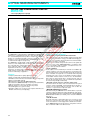
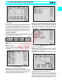
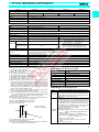
Test Equipment Solutions Datasheet
Test Equipment Solutions Ltd specialise in the second user sale, rental and distribution of
quality test & measurement (T&M) equipment. We stock all major equipment types such as
spectrum analyzers, signal generators, oscilloscopes, power meters, logic analysers etc from
all the major suppliers such as Agilent, Tektronix, Anritsu and Rohde & Schwarz.
We are focused at the professional end of the marketplace, primarily working with customers
for whom high performance, quality and service are key, whilst realising the cost savings that
second user equipment offers. As such, we fully test & refurbish equipment in our in-house,
traceable Lab. Items are supplied with manuals, accessories and typically a full no-quibble 2
year warranty. Our staff have extensive backgrounds in T&M, totalling over 150 years of
combined experience, which enables us to deliver industry-leading service and support. We
endeavour to be customer focused in every way right down to the detail, such as offering free
delivery on sales, covering the cost of warranty returns BOTH ways (plus supplying a loan
unit, if available) and supplying a free business tool with every order.
As well as the headline benefit of cost saving, second user offers shorter lead times, higher
reliability and multivendor solutions. Rental, of course, is ideal for shorter term needs and
offers fast delivery, flexibility, try-before-you-buy, zero capital expenditure, lower risk and off
balance sheet accounting. Both second user and rental improve the key business measure of
Return On Capital Employed.
We are based near Heathrow Airport in the UK from where we supply test equipment
worldwide. Our facility incorporates Sales, Support, Admin, Logistics and our own in-house
Lab.
All products supplied by Test Equipment Solutions include:
- No-quibble parts & labour warranty (we provide transport for UK mainland addresses).
- Free loan equipment during warranty repair, if available.
- Full electrical, mechanical and safety refurbishment in our in-house Lab.
- Certificate of Conformance (calibration available on request).
- Manuals and accessories required for normal operation.
- Free insured delivery to your UK mainland address (sales).
- Support from our team of seasoned Test & Measurement engineers.
- ISO9001 quality assurance.
Test equipment Solutions Ltd
Unit 8 Elder Way
Waterside Drive
Langley
Berkshire
SL3 6EP
T: +44 (0)1753 596000
F: +44 (0)1753 596001
Email: [email protected]
Web: www.TestEquipmentHQ.com
OPTICAL MEASURING INSTRUMENTS
OPTICAL TIME DOMAIN REFLECTOMETER
MW9070B
1.31/1.55 µm (SM), 0.85/1.3 µm (GI)
The MW9070B is a high-performance mini-OTDR for installation and
maintenance of subscriber fiber optic lines and other fiber optic cables. It automatically detects the positions of faults in the cable, and
displays an event table listing faults, and a trace waveform. Despite
the large 7” screen, the high-performance mini-OTDR is just the size
of a B5 file and it weighs in at only 3.2 kg.
The MW9070B is designed with a wide dynamic range and short
dead zone, and is indispensable for detecting faults in optical trunk
lines, subscriber lines, optical CATV cables, optical LANs, and other
types of fiber optic cables. In addition, it is also invaluable in measuring transmission line losses, connection losses, return loss and other
parameters. Six optical units are available depending on the wavelength and type of optical fiber, making the MW9070B an economic
choice for a wide range of applications.
Features
• Compact (smaller than footprint), lightweight (3.2 kg)
• Simple operation with automated fault measurement
• Simultaneous waveform trace and event table display on large LCD
• Built-in 3.5-inch FDD (optional)
• Wide-dynamic range: 36/34 dB (MW0970B/0972B)
• Short dead zone (MW0970B/0972B): 5 m (Event), 25 m (Attenuation)
• High-speed real-time sweep to check fiber connections
• Manual operation for novice and experienced operators
• Visual LD Light Source (option for units)
• Emulation software runs on any personal computer under Microsoft
Windows environment (sold separately)
64
Functions and performance
• Easy operation and fully-automated measurements
In the fully-automatic mode (FULL AUTO), simply pressing the Start
key sets the optimum distance range, pulse width and averaging processing for the optical fiber cable being measured, and automatically detects the positions of any faults.
Furthermore, the real-time sweep function can be used to update the
waveform at 0.4 s sweep (MW0970B/0972B), to confirm the status
of the connected fiber cable in real-time, so trouble from loose connectors can be prevented in advance.
• Event registration
Events (splices, far end, and breaks) in each fiber of a multifiber optical may sometimes occur at the same position. Consequently events
in the first cable that are not detected at the threshold set previously
in the event table are registered on a second fiber when using fully
automatic mode. These events can be added to the table using the
event addition function and then events are set to the Fixed Mode.
Next, when the measurement fiber is changed and the start key
pressed, all of the target events of the second and subsequent fibers
are measured repeatedly and efficiently.
• Automatic optical connector connection status check
This function checks the status of the connection between the optical
connector and the mini-OTDR. It automatically detects whether or
not there are any problems with the connector, such as dirt in the
connector or a poor fit. It then outputs an alarm.
• MX3607B OTDR Emulation Software
Data measured by the MW9070B can be downloaded to a personal
computer, analyzed in detail in the Microsoft Windows environment,
and compared with previously-recorded waveforms using the MX3607B
OTDR Emulation Software. (For details, please refer to the MX3607B
data sheet.)
• 0.01 dB threshold
At periodic inspection of optical fiber cables, it is necessary to check
increases in connection loss due to aging. The loss level that must
not be exceeded as a result of aging can be called the threshold level. The MW9070B allows the threshold to be set anywhere from 0.01
dB to a maximum 9 dB in 0.01 dB increments.
OPTICAL MEASURING INSTRUMENTS
1
Detection of 0.05 dB loss event using 0.01 dB threshold
• Event editing
In fully automatic measurement, splice points with levels below 0.01
dB but which are not judged faults can be added to the event table,
events which were mistakenly determined to be faults due to noise
can be removed, and the events points can be moved and set to
their correct positions. In addition, both ends of the cable can be
specified on the trace waveform (end-to-end registration). These
event editing functions can be used to modify results to produce accurate measurement data. An asterisk is appended to edited events
to discriminate them from other events.
• Saving and printing data
In addition to internal RAM, data can also be saved in memory cards
and on floppy disks. All saved waveforms can be printed at once, or
only selected files can be printed continuously.
Number of saved screens
Medium
Number of screens
Internal RAM
Memory card
(1 MB)
Floppy disk
(2HD, 1.44 MB)
170
280
400
Setup screen <2/3>
Setup screen <3/3>: Automatic backlighting off, automatic power off
The MW9070B can be set so that the backlighting and power are
turned off automatically if no panel operations are performed within
a fixed period of time, helping to save power and permit use over
longer periods of time. In this case, the displayed waveform immediately before auto power-off is backed-up automatically.
Note: The number of screens are for reference only.
• Setup screen
When the power is turned on, the <1/3> to <3/3> setup screen is displayed.
Setup screen <1/3>
When the measurement mode is set to the fully automatic mode, the
optimum distance range, pulse width, and number of averaging times
are set automatically. After averaging, fault positions are detected
automatically.
Setup screen <3/3>
• Function for saving settings
Parameters entered from the setup screen <1/3> can be saved in
dedicated DFN memory. Even after using the panel to change measurement parameters, saved settings can be recalled to return the
MW9070B to its previous setting state.
• Long-distance fiber measurements using wide dynamic range
unit
Setup screen <1/3>
Setup screen <2/3>: Print mode and analysis mode
When saving measurement results in memory, the print mode can be
selected to increase the number of screens that can be saved. Files
saved in the print mode can be printed but cannot be viewed in the
zoom mode or otherwise analyzed in detail. If data analysis is necessary, files should be saved in the analysis mode.
Measurement approx. 147 km single-mode fiber
• Visible LD light source (optical unit: Option 05)
In OTDR measurements, there are some regions (dead zones)
where faults cannot be observed. It is particularly difficult to detect
faults in the dead zone at near end of a fiber cable. A visible LD light
source emitting visible light at 635 nm is connected to the fiber, so
the position where light is leaking from a fault (break, bend) can be
determined. This can also be used for core identification in fibers.
65
OPTICAL MEASURING INSTRUMENTS
Specifications
• MW9070B (main frame)
Display
640 x 480 dot semi-transparent LCD, 7-inch (with backlight on/off function)
Interface
Serial: RS-232C, 1 port (D-sub 9P connector)
Printer: 8 bit parallel (Centronics, D-sub 25P connector)
Keyboard: For IBM US English keyboard (101 keys), DIN 5P
Waveform storage
Internal memory (battery back-up), memory card slot: 1 (memory card slot conforms to PCMCIA R1.0 standard),
3.5-inch FDD: 1 (option), saves GR-196-CORE format files*1
Calendar clock
Displays year, month, day, hour, minute (battery back-up, on/off display)
Auto
measurements
Measurement items
Event distance, loss, return loss, loss from near end, and total return loss
Threshold
Connection loss: 0.01 to 9 dB (in 0.01 dB steps)
Return loss: 20 to 60 dB (in 1 dB steps)
Fiber end: 1 to 10 dB (in 1 dB steps)
No. of detection points
99 max.
Automatic setting items
Pulse width, distance range, averaging times
Event registration function
Event points are registered, and the loss, return loss, etc. for these points are measured and used to create
an event table
Connection check
Manual measurements
On/off switchable
Real-time sweeping, point-to-point distance/loss measurements, point-to-point loss measurements per unit
length, return loss measurements, splice/connection loss measurements and total return loss
Distance unit
m, km, ft, kft, mi
Relative distance measurement
Zero cursor settable
Functions*1
Waveform comparison: Dual or difference waveform display
Variable sampling resolution: Switchable from 1 to 40 m
Shortcut keys: Save, recall, print, switch waveform
Ghost detection: Moves marker to ghost Fresnel reflection and indicates ghost events with ghost marker
Keyboard input
Allows input of file names, titles, headers and event comments
IOR
1.400000 to 1.699999 (in 0.000001 steps)
Title input
32 characters max. (Title Auto-increment*1)
Power supply
Battery: MZ5018A Battery Pack (sold separately), MZ5020A Dry-cell Battery Pack (sold separately)
DC input: 10 to 18 V/14 W
AC input: 90 to 250 V, 50/60 Hz, 50 VA (with SWA1702W AC Adapter: standard accessory)
Dimensions and mass
290 (W) x 194 (H) x 75 (D) mm, ≤3.2 kg (including optical unit and MZ5018A Battery Pack)
Environmental conditions*2
Temperature: –10˚ to +40˚C (operate), –20˚ to +60˚C (storage)
Humidity: 85% (operate and storage)
Vibration: Conforms to MIL-T-28800E (Class 3)
Shock: Height 76 cm, 6 surfaces, 8 corners
EMI: CISPR Pub 22 (Class A)
Dustproofing: MIL-T-28800E
Water-proofing: MIL-T-28800E
EMC*3
EN55011 (1991, Group 1, Class A), EN50082-1 (1992)
Safety
EN61010-1: 1993 (Installation Category ΙΙ, Pollution Degree ΙΙ)
software version 3.0 and later.
*1: Onlyapplied
to AC adapter. When using memory card, limited by memory card’s specifications.
*2:3: Not
* Electromagnetic Compatibility
• MW0970A/B, MW0972A/B, MW0973J, MW0975J Optical Units
(all typical values are given for reference only to assist in the use the unit, and are not guaranteed specifications.)
Model
Fiber
MW0970A
10/125 µm SM fiber
Center wavelength
*
MW0970B
MW0972A
MW0972B
1310 ±30 nm*1
(typical: ±15 nm)
1310/1550 ±30 nm*1
1310/1550 ±30 nm*1
(typical: ±15/20 nm)
ITU-T G.652
1310 ±30 nm*1
Optical connector
FC, ST, DIN, SC, DIAMOND (HMS-10/A)*2
Distance range (km)
5, 10, 25, 50, 100, 200 (200 km is added to only MW0970B/0972B)
Pulse width (ns)
20, 50, 100, 500, 1000, 2000, 4000, 10000 (4000/10000 ns are added to only MW0970B/0972B)
Dynamic range (S/N=1)
23 dB at 1.31 µm*3
(typical: 25.5 dB)
Measurement range*5
15.5 dB at 1.31 µm*3
(typical: 18 dB)
Dead zone
36
*Replaceable and cleanable (all PC type)
dB*4
22 dB*6 (typical: 25 dB)
23 dB at 1.31 µm*3
(typical: 25.5 dB),
20.5 dB at 1.55 µm*3
(typical: 22.5 dB)
36 dB at 1.31 µm*4
34 dB at 1.55 µm*4
15.5 dB at 1.31 µm*3
(typical: 18 dB),
13 dB at 1.55 µm*3
(typical: 15 dB)
22 dB at 1.31 µm*6
(typical: 25 dB),
20 dB at 1.55 µm*6
(typical: 23 dB)
Fresnel reflection
10 m*7
5m
10 m*7
5m
Back-scattered light
50 m*7
25 m*8
50 m*7
25 m*8
Marker-resolution
1 m (at 5 km range)
Accuracy
Distance measurements: ±2 m ± (10–4 x distance) ±marker resolution Excluding uncertainly caused by fiber IOR
Loss measurements (linearity): ±0.05 dB/dB or 0.1 dB (whichever greater)
Return loss measurements: ±4 dB
*
Continued on next page
66
OPTICAL MEASURING INSTRUMENTS
Model
MW0970A
Measurement time*9
MW0970B
MW0972A
MW0972B
0.4 s*10
0.9 s*10
0.4 s*10
180 s max. (auto-measurement mode)
0.9 s*10
Real-time sweep
Dimensions
Safety
Laser: 21CFR Class 1, IEC Class 1
Environmental conditions
Same as mainframe
EMC
Same as mainframe
Model
MW0973J
MW0975J
62.5/125 µm multimode fiber*1
Fiber
850 ±30 nm*12
Center wavelength
(HFS-13/A)*13
850/1300 ±30 nm*12 (typical: ±20 nm)
Optical connector
FC, ST, DIN, SC, DIAMOND
Distance range (km)
5, 10, 25, 50, 100
Pulse width (ns)
20, 50, 100, 500 (500 ns is added to only 1300 nm wavelength)
Dynamic range (S/N=1)
18 dB*14
Measurement range*5
10 dB*14
m*16,
*Replaceable and cleanable (all PC type)
18 dB at 0.85 µm*14 (typical: 22 dB), 22 dB at 1.3 µm*15
10 dB*14, 14 dB*15
6 m at 0.85 µm*16, *17(typical: 5 m*18),
8 m at 1.3 µm*16, *17(typical: 6 m*18)
*17
Fresnel reflection
6
Back-scattered light
15 m*16, *17
Dead zone
*
*
*
*
*
*
*
*
*
*
*
1
290 (W) x 120 (H) x 35 (D) mm
50 m*16(at 0.85/1.3 µm, D=±0.1 dB),
15 m*16 (at 0.85 µm, D=±0.5 dB, typical: 9 m*18),
20 m*16 (at 1.3 µm, D=±0.5 dB, typical: 13 m*18)
Marker-resolution
1 m (at 5 km range)
Accuracy
Distance measurements: ±2 m ± (10–4 x distance) ±marker resolution Excluding uncertainly caused by fiber IOR
Loss measurements (linearity): ±0.05 dB/dB or 0.1 dB (whichever greater)
Return loss measurements: ±4 dB
Measurement time*9
180 s max. (auto-measurement mode)
*
Real-time sweep
1.0 s*19
Dimensions
290 (W) x 120 (H) x 35 (D) mm
Safety
Laser: 21CFR Class 1, IEC Class 1
Environmental conditions
Same as mainframe
EMC
Same as mainframe
1: Pulse width of 1 µs at 25˚C
2: One of these connectors is attached. D4 and Biconic connectors are factory options (not user replaceable)
3: Pulse width of 2000 ns during auto-measurement
4: Pulse width of 10 µs at 25˚C
5: 0.5 dB splice detectable range with ±0.1 dB accuracy (test method of optical unit for SM fiber depends on Bellcore TR-NWT-001138)
6: Pulse width of 4 µs during auto-measurement
7: At ≥25 dB return loss with 20 ns pulse width
8: At ≥40 dB return loss with 20 ns pulse width
9: Measurement time is the period from when the start key is pressed until
the measurement results is displayed in the displayed in the table with fullauto mode. This time changes according to the fiber loss, pulse width, and
level of Fresnel reflection, and to whether or not distance range and pulse
width are set to Auto. The typical measurement time is 45 seconds when
measuring a 5 km fiber (0.35 dB/km loss) at a wavelength of 1.31 µm with
distance range and pulse width to set Auto.
10: For loss measurements (2 point method) of 25 km fiber, the 50 km distance range and displayed with full scale (5 km/div).
11: When used with 50/125 µm fiber, the dynamic range is decreased by approx. 4 dB, and the dead zone (defined using 0.5 dB back-scattered light)
will increase to approx. 20 m at 850 nm, and 30 m at 1300 nm.
12: Pulse width of 100 ns at 25˚C
13: One of these connectors is attached. D4, Biconic and Amphenol 906 connectors are factory options (not user replaceable).
14: 100 ns pulse width during auto-measurement
15: 500 ns pulse width during auto-measurement
16: Refer to the figure below
• MW9070B Option 01: Built-in 3.5-inch FDD
Storage media
MS-DOS
Capacity
2DD: 720 KB, 2HD: 1.44 MB
File copying
Between FD, memory card and internal memory
Operating temperature
+5˚ to +40˚C
Operating humidity
≤80%
Operating conditions
Horizontal or tilted
Mass
≤300 g
• MW9070B Option 02: Monitoring function
Form
Installed in MW9070B Optical Time Domain Reflectometer
Functions
Detects optical fiber faults (quick scan, normal scan, and
near-end scan), scheduler, modem/communication setting,
controls alarm generator and optical switch (eight ports for
optical switches and alarm generator)
Installation
program
Functions
Reads and records files, sets OTDR measurement conditions,
executes OTDR measurement, reads OTDR waveform, manipulates waveform, sets optical switches and alarm ports,
sets OTDR modem, select reference data type, sets fault
threshold value, sets evaluation range, saves reference data,
creates/downloads/executes scheduler, sets serial port/
modem, connects/disconnects network
Operating requirements
Computer: i486TM or higher processor (Pentium 75 MHz or
higher recommended) running Windows95
Memory required:
16 MB or more (32 MB or more recommended)
Hard disk required: 16 MB or more free space (20 MB or
more recommended)
FDD: 3.5” (1.44 MB) x 1 drive
Display: 800 x 600 or higher resolution color monitor
Mouse
RS-232C: 1 port or more
*
*
*
*
*
1.5 dB
ι1: Fresnel reflection
ι 2: Back-scattered light
D
1
2
At ≥20 dB return loss with 20 ns pulse width
*17: Typical
value at ≥30 dB return loss
*18:
loss measurements (2 point method) of 2 km fiber, the 5 km distance
*19: For
range and displayed with full scale (500 m/div).
3.5” FD (2DD, 2HD)
Format
67
OPTICAL MEASURING INSTRUMENTS
• Optical units Option 05: Visual LD light source
Ordering information
Please specify model/order number, name and quantity when ordering.
Wavelength
635 nm ±10 nm at 25˚C
Output
–3.0 ±1.5 dBm (blinks at constant intervals*1)
Output fiber
10/125 µm, SM fiber
Optical connector
FC, SC, ST, DIN, Diamond (user replaceable),
D4, Biconic (factory option)
MW9070B
Optical safety
IEC 825 Class 2, FDA (21CFR 1040.10) Class 2
Environmental conditions
See respective units
SWA1702W
*1: Only software version 3.0 and later
Safety measures for laser products
This option complies with the optical safety standards in Class 2 of
the IEC pub. 825 and the FDA (21CFR 1040.10, USA); the following
descriptive labels are affixed to the product (FDA label is only affixed
to product for export to the USA).
Model/Order No.
W1046AE
W1047AE
W1046BE
MW0970A
MW0970B
MW0972A
MW0972B
MW0973J
MW0975J
Optical units
SMF 1.31 µm Unit (economy type)
SMF 1.31 µm Unit (wide-dynamic range type)
SMF 1.31/1.55 µm Unit (economy type)
SMF 1.31/1.55 µm Unit (wide-dynamic range type)
GIF 0.85 µm Unit
GIF 0.85/1.3 µm Unit
Standard accessory (optical unit)
Replaceable optical connector*1:
*
*
• MZ5018A Battery Pack
Power, capacity
10.8 V, 2.8 AH (nominal value)
Type
Ni-Cd secondary cell
Charging time
14 hours (at 25˚C using SWA1702W AC adapter)
Temperature range
when charging
0˚ to +40˚C
Drive time
≥5 hours (at 25˚C with backlight off)
Dimensions
290 (W) x 74 (H) x 35 (D) mm
• MZ5020A Dry-cell Battery Pack
Batteries
Ten C/BABY-size alkaline or manganese (LR14,
R14) dry cells (provided by user)
Life*1
4 hours (backlight on), 13 hours (backlight off)
Ambient temperature
Same as main frame
Dimensions and mass
290 (W) x 74 (H) x 35 (D) mm, ≤ 450 g
(excluding batteries)
*1: Typical continuous at room temperature using LR14 dry cells
• SWA1702W AC adapter (Tamura Corporation)
90 to 250 Vac, 50/60 Hz
DC output
17.5 Vdc, 1.2 A
Dimensions
163 (W) x 36 (H) x 63 (D) mm
Safety standards
UL1950, CSA1402C, EN60-950
Temperature
0˚ to +40˚C (operate), –10˚ to +70˚C (storage)
Humidity
90% (operate), 95% (storage)
• MX3607B OTDR Emulation Software
Functions*1
Waveform display, manual measurement, auto search, auto
zoom, event editing, continuous printing, waveform comparison, waveform difference, both ends measurement, multiwaveform display, text output
Operating
environment
Personal computer: i486TM or higher processor, and capable
of running Microsoft Windows 3.1 or Windows 95
OS: Microsoft Windows 3.1 or Windows 95
Memory required: 8 MB to run this program
Hard disk required: At least 5 MB of free disk space
FDD: 3.5” (1.44 MB) x 1 drive
Display: 640 x 480 dots or higher resolution color monitor
Others: Mouse or other pointing device
*1: Supported in MX3607B version 2.0 or later
68
1
1
1
1
1
1
pc
pc
copy
copy
copy
copy
1 pc
MZ5018A
MZ5020A
Battery pack
Battery Pack (Ni-cd secondary cell)
Dry-cell Battery Pack [Ten C/BABY size alkaline or
manganese (LR14, R14) dry cells (provided by user)]
MX3607B
Application software
OTDR Emulation Software
Supplied on 3.5” FD (2HD), includes setup program
FDA (CFR)
The maximum output is indicated under 1, and the wavelength under 2.
Caution: Do not look directly into the laser beam.
AC input
Main frame
Optical Time Domain Reflectometer
Standard accessories (main frame)
AC adapter (Tamura Corporation):
Power cord, 2.5 m:
Short-cut label:
MW9070B operation manual:
MW9070B serial interface manual:
MW9070B service manual:
*2
IEC
Name
W1058AE
Standard accessory for MX3607B
MX3607B operation manual:
MW9070B-01
MW9070B-02
MW9070B-10
MW9070B-12
MW9070B-13
MW9070B-14
MW9070B-15
MW9070B-17
MW9070B-18
MW9070B-19
Options (main frame)
3.5-inch FDD
Monitoring function
English language display*2
German language display*2
French language display*2
Italian language display*2
Spanish language display*2
Japanese language display*2
Chinese language display*2
Finnish language display*2
MW0970A-05
MW0970B-05
MW0972A-05
MW0972B-05
MW0973J-05
MW0975J-05
MW0970A-21
MW0970B-21
MW0972A-21
MW0972B-21
MW0973J-21
MW0975J-21
MW0970A-22
MW0970B-22
MW0972A-22
MW0972B-22
MW0973J-22
MW0975J-22
MW0973J-23
MW0975J-23
Options (optical unit)
Visible LD light source for MW0970A*3 (factory option)
Visible LD light source for MW0970B*3 (factory option)
Visible LD light source for MW0972A*3 (factory option)
Visible LD light source for MW0972B*3 (factory option)
Visible LD light source for MW0973J*3 (factory option)
Visible LD light source for MW0975J*3 (factory option)
D4 connector (factory option)
D4 connector (factory option)
D4 connector (factory option)
D4 connector (factory option)
D4 connector (factory option)
D4 connector (factory option)
Biconic (AT&T) connector (factory option)
Biconic (AT&T) connector (factory option)
Biconic (AT&T) connector (factory option)
Biconic (AT&T) connector (factory option)
Biconic (AT&T) connector (factory option)
Biconic (AT&T) connector (factory option)
Amphenol 906 connector*4 (factory option)
Amphenol 906 connector*4 (factory option)
1 copy
Continued on next page
OPTICAL MEASURING INSTRUMENTS
Model/Order No.
MW0970A-38
MW0970B-38
MW0972A-38
MW0972B-38
MW0973J-38
MW0975J-38
MW0970A-39
MW0970B-39
MW0972A-39
MW0972B-39
MW0973J-39
MW0975J-39
MW0970A-40
MW0970B-40
MW0972A-40
MW0972B-40
MW0973J-40
MW0975J-40
MW0973J-42
MW0975J-42
MW0970A-43
MW0970B-43
MW0972A-43
MW0972B-43
MW0970A-45
MW0970B-45
MW0972A-45
MW0972B-45
MW0973J-45
MW0975J-45
Z0301A
JS256G3-C-13
JS512G3-C-13
JS1024G3-C-13
JS2048G3-C-13
FC-AP
J0635[ ]*5
MZ8012A
Z0242
Z0243
J0617B
J0618D
J0618E
J0618F
J0619B
J0699[ ]*5
J0700[ ]*5
J0701[ ]*5
J0654A
J0661A
Name
ST connector (user replaceable)
ST connector (user replaceable)
ST connector (user replaceable)
ST connector (user replaceable)
ST connector (user replaceable)
ST connector (user replaceable)
DIN connector (user replaceable)
DIN connector (user replaceable)
DIN connector (user replaceable)
DIN connector (user replaceable)
DIN connector (user replaceable)
DIN connector (user replaceable)
SC connector (user replaceable)
SC connector (user replaceable)
SC connector (user replaceable)
SC connector (user replaceable)
SC connector (user replaceable)
SC connector (user replaceable)
DIAMOND (HFS-13/A) connector (user replaceable)
DIAMOND (HFS-13/A) connector (user replaceable)
DIAMOND (HMS-10/A) connector (user replaceable)
DIAMOND (HMS-10/A) connector (user replaceable)
DIAMOND (HMS-10/A) connector (user replaceable)
DIAMOND (HMS-10/A) connector (user replaceable)
FC connector (user replaceable)
FC connector (user replaceable)
FC connector (user replaceable)
FC connector (user replaceable)
FC connector (user replaceable)
FC connector (user replaceable)
Optional accessories
Keyboard
256 KB memory card (conforms to PCMCIA R1.0)
512 KB memory card (conforms to PCMCIA R1.0)
1024 KB memory card (conforms to PCMCIA R1.0)
2048 KB memory card (conforms to PCMCIA R1.0)
Adapter
Optical fiber cable (with FC-PC at both ends, SM)
Connector Cleaning Set
Soft carrying bag
Hard carrying case (holds main frame and thermal printer)
Replaceable optical connector (FC)
Replaceable optical connector (ST)
Replaceable optical connector (DIN)
Replaceable optical connector (HMS-10/A, HFS-13/A)
Replaceable optical connector (SC)
FDDI-FC conversion cord
FDDI-ST conversion cord
FDDI-SC conversion cord
Serial interface cable (for remote control with IBM-PC/AT
or J-3100)
Serial interface cable (for connection with peripherals)
J0614
Peripherals
Thermal printer (120 V ±10%, 60 Hz, 0˚ to +40˚C,
Seiko Instruments Inc., printer cable sold separately)
Thermal printer (220 V ±10%, 50 Hz, 0˚ to +40˚C,
Seiko Instruments Inc., printer cable sold separately)
Printer connection cable (parallel)
TP411-28CL
Supplies
Printer paper for DPU-411-21BU/BE (10 rolls/set)
DPU-411-21BU
DPU-411-21BE
1
one of FC, ST, DIN, SC or DIAMOND. When the connector type is
*1: Specify
not specified, FC is supplied.
language is not specified, the English version is installed.
*2: If the display
with same connector as optical unit.
*3:4: Supplied
* FC type and dead zone is varied.
*5: Specify the optical fiber length as A, B, or C (A: 1 m, B: 2 m, C: 3 m).
MS-DOS is a registered trademark of Microsoft Corporation.
Windows is a registered trademark of Microsoft Corporation.
IBM is a registered trademark of International Business Machines Corporation.
i386/i486 are trademarks of Intel Corporation.
69