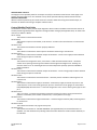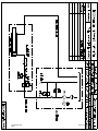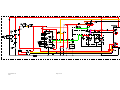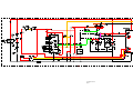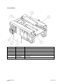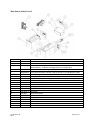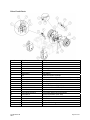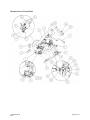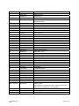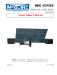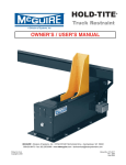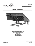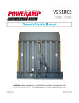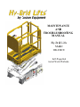
1
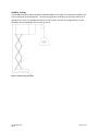
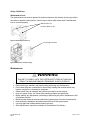
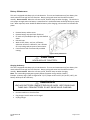
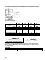
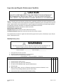
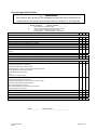
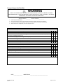
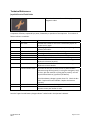
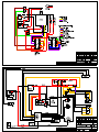
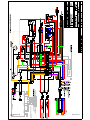
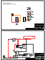
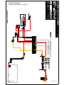
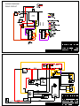
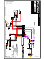
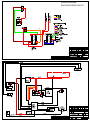
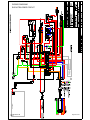
MAIINTEN NANC CE AND D T TROUB BLESH HOOT TING M MANU UAL H Hy-Bridd Lifts Moddel HB-8330CE Self-Proopelled Aerial Workk Platform m TableofContents Safety ............................................................................................................................................................ 5 Safety Symbols .......................................................................................................................................... 5 General Rules and Precautions ................................................................................................................. 5 Stability Testing ......................................................................................................................................... 6 Safety Guidelines ...................................................................................................................................... 7 Maintenance Lock ..................................................................................................................................... 7 Maintenance ................................................................................................................................................. 7 Battery Maintenance ................................................................................................................................ 8 Lubrication ................................................................................................................................................ 9 Components requiring adjustment ......................................................................................................... 10 Examination, repair, replacement of limited life components ............................................................... 10 Safety devices and systems requiring checks ......................................................................................... 10 Storage .................................................................................................................................................... 10 Major Alterations or Repairs ................................................................................................................... 10 Inspection and Regular Maintenance Checklists ........................................................................................ 11 Monthly Battery Care .............................................................................................................................. 11 Prestart Inspection Checklist .................................................................................................................. 12 Frequent Inspection Checklist ................................................................................................................. 13 Pre‐Delivery/Annual Inspection Checklist ............................................................................................... 14 Technical References .................................................................................................................................. 15 Joystick Service Flash Codes ................................................................................................................... 15 Control Module—GP102 Help Messages ................................................................................................ 16 Control Module Flash Codes ................................................................................................................... 18 Hydraulic Schematic ................................................................................................................................ 19 Electrical Schematic ................................................................................................................................ 20 Wiring Diagrams .......................................................................................................................................... 22 Wiring Diagram ....................................................................................................................................... 22 Main Power & Safety .............................................................................................................................. 24 Drive Circuit ............................................................................................................................................. 26 Elevate/Lower Circuit .............................................................................................................................. 28 Troubleshooting .......................................................................................................................................... 30 Part #SUPO-613E REV J Page 2 of 42 Troubleshooting Flowchart ..................................................................................................................... 30 Troubleshooting Flowchart—Drive& Steer Circuit ................................................................................. 32 Troubleshooting Flowchart—Elevate & Lower Circuit ........................................................................... 34 Replacement Parts ...................................................................................................................................... 36 Safety and Control Decals ....................................................................................................................... 36 Covers/Other........................................................................................................................................... 37 Main Power/Safety Circuit ...................................................................................................................... 38 Drive Circuit Parts ................................................................................................................................... 39 Elevate/Lower Circuit Parts ..................................................................................................................... 40 Warranty ..................................................................................................................................................... 42 Figure 1: Stability Testing, Equivalent ........................................................................................................... 6 Figure 2: Maintenance Lock Pin Use ............................................................................................................. 7 Figure 3: Maintenance Lock Pin Storage ....................................................................................................... 7 Figure 4: Battery Maintenance ..................................................................................................................... 8 Figure 5: Battery Charger LED Display .......................................................................................................... 9 Revision Table: Revision A (06/29/2010): Initial Release Revision J (10/24/2012): Revised logos Part #SUPO-613E REV J Page 3 of 42 Original instructions are written in English Foreword The purpose of this Maintenance Manual is to provide qualified service personnel with information for servicing and maintaining Hy-Brid Lifts. All information in this manual must be read and understood before any attempt is made to service this machine. The operation and safety manual is considered a part of the work platform and contains instructions and operating procedures essential to properly and safely operate the Custom Equipment Hy-Brid Lift. Users must read and understand all information in the Safety and Operations Manual before operation. DANGER THE OPERATION AND SAFETY MANUAL MUST BE READ AND UNDERSTOOD PRIOR TO OPERATING THE MACHINE. THE USER/OPERATOR SHOULD NOT ACCEPT OPERATING RESPONSIBILITY UNTIL THE MANUAL HAS BEEN READ AND UNDERSTOOD AS WELL AS HAVING OPERATED THE LIFT UNDER SUPERVISION OF AN EXPERIENCED AND QUALIFIED OPERATOR. BECAUSE THE MANUFACTURER HAS NO DIRECT CONTROL OVER MACHINE APPLICATION AND OPERATION, PROPER SAFETY PRACTICES ARE THE RESPONSIBILITY OF THE USER AND ALL OPERATING PERSONNEL. WARNING ANY MODIFICATION ON THIS MACHINE WITHOUT THE EXPRESS WRITTEN CONSENT OF THE MANUFACTURER IS PROHIBITED. If there is a question on application and/or operation, contact: Custom Equipment, Inc. 2647 Hwy 175 Richfield, WI 53076 USA Phone: 262-644-1300 Fax: 262-644-1320 www.hybridlifts.com Part #SUPO-613E REV J Page 4 of 42 Safety Safety Symbols DANGER FAILURE TO FOLLOW THIS WARNING WILL CAUSE DEATH OR PERSONAL INJURY. WARNING FAILURE TO FOLLOW THIS WARNING MAY CAUSE DEATH OR PERSONAL INJURY. "DANGER" indicates an imminently hazardous situation, which, if not avoided, will result in death or serious injury. "WARNING" indicates a potentially hazardous situation, which, if not avoided, could result in death or serious injury "CAUTION" indicates a potentially hazardous situation which, if not avoided, could result in FAILURE TO FOLLOW THIS WARNING minor or moderate injury or damage to MAY CAUSE INJURY OR DAMAGE EQUIPMENT equipment CAUTION General Rules and Precautions Custom Equipment, Inc. designed the Hy‐Brid Lift self‐propelled scissor lift to be safe and reliable. It is intended for elevating personnel, along with their necessary tools and materials to overhead work locations. Vibration does not create significant hazards on this machine. An operator of any type of work platform is subject to certain hazards that cannot be protected by mechanical means. It is therefore essential that operators be competent, careful, physically and mentally fit and thoroughly trained in safe operation of this machine. Although Custom Equipment, Inc. conforms to specified EN: 280 requirements, it is the responsibility of the owner to instruct operators with the safety requirements made not only by Custom Equipment, Inc., but by the various safety boards in your area, as well as additional requirements set forth by EN: 280 If you come across a situation that you think might be unsafe, stop the platform and request further information from qualified sources before proceeding. WARNING MAINTENANCE INFORMATION IS FOR USE BY TRAINED PERSONNEL ONLY WARNING NEVER REACH BETWEEN SCISSORS LINKS OR PROP UP PLATFORM UNLESS MAINTENANCE PINS ARE IN PLACE. Part #SUPO-613E REV J Page 5 of 42 Stability Testing The HB‐830CE has been stability tested to standards EN280 or AS 14180. The most adverse stability test is the traveling forward configuration. The overturning moment created by the test loads and forces is equivalent to a test on an unloaded machine on a level surface, as shown in the figure below. For the HB‐830CE, the test weight/pull force is 50.3 kg /111 lb. Figure 1: Stability Testing, Equivalent Part #SUPO-613E REV J Page 6 of 42 Safety Guidelines Maintenance Lock The maintenance lock must be placed into position whenever the machine is being serviced in the raised or partially raised position. Serious injury and/or death could result if maintenance lock is not used properly. Maintenance Pin Location When in Use Figure 2: Maintenance Lock Pin Use Pin Storage Location Figure 3: Maintenance Lock Pin Storage Maintenance WARNING • • • • • • • • • • FAILURE TO COMPLY WITH THE LISTED SAFETY PRECAUTIONS MAY RESULT IN MACHINE DAMAGE, PERSONNEL INJURY OR DEATH. Never work under an elevated platform until maintenance locks have been engaged. Remove all rings, watches, and jewelry when performing any maintenance. Do not wear long hair unrestrained or loose fitting clothing and neckties which may become caught on or entangled in equipment. Observe and obey all warnings and cautions on machine and in manual. Keep oil, grease, water, etc. wiped from standing surfaces and handholds. Before making any adjustments, lubricating or performing any other maintenance, shut off all power controls. Battery should always be disconnected during replacement of electrical components. Keep all support equipment and attachments stowed in their proper place. Use only approved nonflammable cleaning solvents. After maintenance, inspect the machine as described for Pre-delivery. Part #SUPO-613E REV J Page 7 of 42 Battery Maintenance This unit is equipped with deep cycle 12‐volt batteries. The care and maintenance of your battery has much to do with how well this unit functions. Battery wiring and water level should be checked monthly. Do not overfill. When the cells are too full, fluid will seep out when charging. The solution is at its proper strength when the battery is manufactured. Use distilled water and keep fluid up to proper level. When required, water should be added to battery after charging, unless water level is below the plates. • Remove battery cabinet cover. • Remove battery caps and check fluid level. • Fill each cell (if needed) to split ring with distilled water. • Reinstall caps. • Wash all dirt, debris, acid, etc., off battery whenever corrosion is detected. Use a solution of 5‐tsp. baking soda per quart of warm water. • Coat terminals with a commercially available coating. Figure 4: Battery Maintenance CAUTION NEVER ADD ACID TO BATTERY! Charging the Battery This unit is equipped with deep cycle 12‐volt batteries. The care and maintenance of your battery has much to do with how well this unit functions. Battery wiring and water level should be checked monthly. Do not overfill. When the cells are too full, fluid will seep out when charging. Note: The surrounding temperature greatly affects the power reserve within a battery. Example: A battery that is 100% charged at 80° F (27°C) drops to 65% at 32°F (0°C) At 0°F (‐18°C), this battery will drop to 40% efficiency. WARNING LEAD-ACID BATTERIES GENERATE EXPLOSIVE GASES. KEEP SPARKS AND FLAME AWAY FROM BATTERIES. DO NOT SMOKE WHILE CHARGING. • Park the machine on a level surface. • Plug charger into AC outlet until charged. • Unplug charger. Part #SUPO-613E REV J Page 8 of 42 The charger will not begin charging on severely discharged batteries. This will be evident by the three indicators blinking simultaneously. Figure 5: Battery Charger LED Display 50% 75% 100% GEL 0 to 50% charged Blinking Off Off NA 50% to 75% charged On Blinking Off NA 75% to 100% charged On On Blinking NA 100% charged On On On NA Charge for flooded type batteries NA NA NA Off Charge for Sealed type batteries NA NA NA On Abnormal Cycle Off Off Blinking NA Charger LED Display Charging State WARNING DO NOT OPERATE UNIT WHILE CHARGING. DO NOT DISABLE CHARGER INTERLOCK. CAUTION NEVER ADD ACID TO BATTERY! The solution is at its proper strength when the battery is manufactured. Use distilled water and keep fluid up to proper level. When required, water should be added to battery after charging, unless water level is below the plates. Lubrication Item Wheels Part #SUPO-613E REV J Specification Teflon Spray Frequency of Lubrication Quarterly Page 9 of 42 Components requiring adjustment Under normal use, no components should require adjustment. Contact the manufacturer if adjustments are required. Examination, repair, replacement of limited life components With proper use, battery maintenance, and regular inspection, there are no limited life components that require routine replacement. Safety devices and systems requiring checks Check safety functions as part of daily inspection. Check that the electromagnetic brakes are holding. Storage After periods of storage, exposure to extremes of ambient conditions‐heat, cold, moisture, dust etc. inspect the machine. Refer to the Pre‐Delivery/ Frequent Inspection Checklist in the Maintenance Manual. Major Alterations or Repairs Any alterations must be approved by the manufacturer. Major repairs, which affect the stability, strength, or performance of the machine must also be approved by the manufacturer, recorded, and include machine inspection and testing. Never attach pipe racks, material lifting devices, or make any other alteration that is not part of the intended design of the machine. Part #SUPO-613E REV J Page 10 of 42 Inspection and Regular Maintenance Checklists CAUTION FAILURE TO PERFORM INSPECTIONS AND PREVENTITIVE MAINTENANCE AT RECOMMENDED INTERVALS MAY RESULT IN THE UNIT BEING OPERATED WITH A DEFECT THAT MAY RESULT IN INJURY OR DEATH OF THE OPERATOR. Regular inspection and conscientious maintenance is important to efficient economical operation of this machine. It will help to assure that equipment will perform satisfactorily with a minimum of service and repair. Make checks at the stated intervals or more frequently if required by local operating conditions. The following inspection checklists are required and included in this manual: Pre‐Start (Required before operation at each work shift) Monthly Battery Maintenance Frequent (Required at intervals not more than three months) Pre‐Delivery/Annual (Required at intervals not more than twelve months) The rated life of the machine is Light Intermittent Duty (typical use 10 years, 40 weeks per year, 20h per week, 5 load cycles per h). Monthly Battery Care WARNING THIS CHECKLIST MUST BE USED AT MONTHLY OR AFTER EVERY 100 HOURS OF USE. FAILURE TO DO SO COULD AFFECT THE SAFETY OF THE OPERATOR. MODEL NUMBER _____________ SERIAL NUMBER ______________ 1. 2. 3. Keep inspection records up‐to‐date. Record and report all discrepancies to your supervisor. A dirty machine cannot be properly inspected. Y‐Yes/Acceptable N‐No/Unacceptable R‐Repaired Description Y N Monthly Battery Care: 1. Remove battery cabinet cover. 2. Remove battery caps and check fluid level. 3. Fill each cell (if needed) to split ring with distilled water. 4. Reinstall caps. 5. Wash all dirt, debris, acid, etc., off battery whenever corrosion is detected. Use a solution of 5‐tsp. baking soda per quart of warm water. 6. Coat terminals with a commercially available coating. Part #SUPO-613E REV J Page 11 of 42 R Prestart Inspection Checklist WARNING THIS CHECKLIST MUST BE USED AT THE BEGINNING OF EACH SHIFT OR AFTER EVERY SIX TO EIGHT HOURS OF USE. FAILURE TO DO SO COULD AFFECT THE SAFETY OF THE OPERATOR. MODEL HB830CE 1. 2. 3. SERIAL NUMBER ______________ Keep inspection records up-to-date. Record and report all discrepancies to your supervisor. A dirty machine cannot be properly inspected. Y-Yes/Acceptable N-No/Unacceptable R-Repaired Y Description N Visual Inspections Check that there are no damaged, dented, or bent structural members. There are no loose or missing parts. Check that warning and instructional labels are legible and secure. Ensure that load capacity is clearly marked. Check the platform rails and safety gate for damage. Platform and base controls are not missing, damaged, or disconnected. Electrical cables and wires are not torn, frayed, or disconnected. Hydraulic hoses are not torn or loose, and there are no leaks. Check that hoses and the cables have no worn areas or chafing. Check the hydraulic fluid level with the platform fully lowered. Check the tires for damage. Check that wheel axle retaining rings and set screw in rear wheel are tight. Check that all snap rings are secure in grooves on pivot pins. Functional Tests Gate closes automatically and latches (alignment can be adjusted with screw on toe board or railing if necessary). Platform Controls: Check all switches and push buttons for proper operation. Emergency Stop (Stops all movement) Drive Enable (Must be activated to drive) Joystick (Return to neutral, drives forward, reverse, left, right) Lift Enable (Must be activated to elevate) Rocker Switch (Elevates, Lowers) Horn Tilt & Overload LED Indicators Base Controls: Check all switches and push buttons for proper operation. Emergency Stop (Stops all movement) Key Switch (Selects Platform Control, Ground Control, or Off) Up/Down Rocker Switch (Elevates, Lowers) Hour meter (Displays Drive Hours) Alarms (Not damaged, sounds for descent, overload) LED (Flashes when overloaded) Wheels: Front and rear wheels rotate, pivot freely. Drives in slow speed when elevated. Brakes: Machine stops when joystick released. Pothole guards deploy and lock when platform is raised. Lift does not elevate when pothole guards are blocked. DATE _______________ INSPECTED BY ____________________________ Part #SUPO-613E REV J Page 12 of 42 R Frequent Inspection Checklist WARNING AERIAL PLATFORMS SHALL BE INSPECTED, SERVICED AND ADJUSTED TO MANUFACTURER'S REQUIREMENTS BY A QUALIFIED MECHANIC PRIOR TO EACH SALE, LEASE, OR RENTAL, AND EVERY 3 MONTHS OR 150 HOURS, WHICHEVER COMES FIRST. MODEL NUMBER ___________ SERIAL NUMBER ______________ • • • • Check each item listed below. Use proper operating, service, and maintenance manual for specific information and settings If an item is found to be unacceptable make the necessary repairs and check the “repaired” box. When all items are “acceptable”, the unit is ready for service. Description Y N Visual Inspections Perform all checks on the Pre‐Start Inspection Checklist. Inspect the condition of hydraulic fluid in reservoir. Oil should have a clear amber color. Inspect the entire machine for signs of damage, broken welds, loose bolts, or improper repairs. (Check for corrosion, cracking, abrasion, etc.) Check that all snap rings are secure in grooves on pivot pins. Check if tires are leaning in or out. Check electrical motor brushes (every 150 hours) Verify that maintenance and inspection records are up to date. Functional Tests Perform all checks on the Pre‐Start Inspection Checklist. Functions operate smoothly. Functions operate over full range of motion. Elevated and Lowered drive speeds do not exceed specifications listed in Operators manual. Emergency Lowering—Manual override functions properly. Ground Controls override platform controls. Check that the platform does not drift down with a full load. Wheels lubricated if needed. Comments: DATE _______________ INSPECTED BY _______________________________ Part #SUPO-613E REV J Page 13 of 42 R PreDelivery/Annual Inspection Checklist WARNING AERIAL PLATFORMS SHALL BE INSPECTED, SERVICED AND ADJUSTED TO MANUFACTURER'S REQUIREMENTS BY A QUALIFIED MECHANIC PRIOR TO EACH SALE, LEASE, OR RENTAL, AND EVERY 12 MONTHS. MODEL NUMBER: HB830CE SERIAL NUMBER ______________ • • • • Check each item listed below. Use proper operating, service, and maintenance manual for specific information and settings If an item is found to be unacceptable make the necessary repairs and check the “repaired” box. When all items are “acceptable”, the unit is ready for service. Check Y N R Base: Inspect roller tracks for damage All frame bolts tight Pump Secure DC motors secure Battery Hold Downs Secure Batteries Fully Charged Wheels: Snap Rings Secure Wheels: Bolts/Nuts Tight Maintenance Locks: Pins in cabinet All Shields/Guards in place Hydraulic Oil Level 1” from top Check all hydraulic hoses for leaks Check all hydraulic fittings for leaks Scissors: Broken Welds Bent Beam Members All rollers Turn Freely Ret. Rings Secure On Pivots Broken welds Platform: All rails in place/secure No bent rails No broken welds 110V outlet safe/working (if installed) Entrance gate Closes Freely Operator/Service Manual Included Cables in place/secure Extending platform extends freely Extending platform Locks in Stowed Position Extending platform Locks in Extended Position Comments: Check Y N R Decals: Legibility Correct capacity noted Proper placement quantity Wiring: Switches secure Contactor(s) secure Tight on terminals (No loose wiring) Functions: Drive, Lift, Steer Functions Operational Emergency Stop Breaks Circuits Slow Speed limit switch Set properly Emergency Down Operational Pothole guards deploy when platform Pothole interlock functions correctly Brakes: Operational Tilt sensor Functional Warning Horn Alarms Motion Alarms Functional Hour meter operational Battery indication operational Verify Overload Calibration Battery Charger Secure/Operational DATE _______________ INSPECTED BY _______________________________ Part #SUPO-613E REV J Page 14 of 42 Technical References Joystick Service Flash Codes The amber Service Indicator LED displays diagnostic codes. A sequence of flashes, separated by a pause, followed by a repetition of the sequence. The number of flashes indicates a condition. Flash Code Description Notes 1 User Fault Possible stall timeout or user error. Release the joystick to neutral and try again. 2 Battery Fault Try charging batteries. Batteries may require replacing. Check batteries and cables. 3 Left Motor Fault Check left motor, connections, and cabling 4 Right Motor Fault Check right motor, connections, and cabling. 5 Left Park Brake Fault Check left park brake, connections, and cabling. 6 Right Park Brake Fault Check the right park brake, connections and cabling 7 Remote Fault Check the Communications Bus connectors and wiring. Replace the Remote (Joystick). 8 Power Module Fault Check the Communications Bus connectors and wiring. Replace the Power Module. 9 Communications Fault One cause of this error is when the unit is powered down without turning off the joystick (i.e. using the emergency stop). To clear, with the machine on (using the key switch), turn the joystick off and back on (joystick on/off button). Check that battery voltage is greater than 17V. Check the Bus Cable. Replace the Power Module. Replace the Remote (Joystick). 10 Unknown Fault Check all connections and wiring. Contact manufacturer. 11 Incompatible Remote The Remote is incompatible with the Power Module. Ensure that the correct part number is used. See also “Upper Control Battery Gauge Indicator” codes listed in the Operator’s Manual. Part #SUPO-613E REV J Page 15 of 42 Control Module—GP102 Help Messages When the EZcal hand‐held device is connected to the GP102 control module, the first menu available is “HELP” – just press the ENTER button to see a message describing the current status of the GP102; this can be very helpful in diagnosing problems with the system. When an EZcal is unavailable, an LED on the GP102 flashes to provide limited diagnostics (see Appendix Four). The following messages might be displayed: EVERYTHING OK The GP102 is in platform mode and detects no problems. If problems are being experienced with the system, use the DIAGNOSTICS menus to check for faulty sensors and/or switches. LED on steady. IN GROUND MODE! The GP102 is in ground mode and detects no problems. IMPORTANT: Normally the overload cutout system is inhibited in ground mode. The vehicle should not be used to raise heavy loads in ground mode, in case the platform is overloaded. LED on steady. ARMGUARD ACTIVE! The GP102 has stopped descent at the Armguard height, and is delaying to “give the operator the opportunity to see whether persons … could be injured” (per EN 280 5.4.4). Vehicle movement will continue to be stopped after the delay until all functions are released. LED flash code 4. B+ SUPPLY TOO LOW The GP102 is designed for use on 12V and 24V battery powered vehicles; it cannot operate with a supply below about 9V. The “BATTERY” voltage can be checked in the “SENSORS” menu (available in the “DIAGNOSTICS” menu). LED flash code 7. DRIVE/LIFT SELECT INPUTS FAULTY! Neither the drive select (P2‐7) nor the lift select (P2‐8) input is active, or both are active – the GP102 cannot determine the vehicle use. All vehicle operation will be prevented until the problem is corrected. LED flash code 2. ELEVATION SWITCH SHIFTED? The GP102 uses the elevation switch in combination with the height sensor to ensure correct functionality of both; any of the following faults may be detected: • The elevation switch should change state near the point at which it did during load calibration All vehicle operation will be prevented until the problem is corrected. LED flash code 4. ELEVATION SWITCH STUCK? The GP102 uses the elevation switch in combination with the height sensor to ensure correct functionality of both; any of the following faults may be detected: • When the platform is elevated, the measured height should be above that stored during load calibration. • When the platform is not elevated, the measured height should be below that stored during load calibration. All vehicle operation will be prevented until the problem is corrected. LED flash code 4. EMS INPUTS FAULTY! The EMS platform (P2‐1) and EMS ground (P2‐2) inputs are either both active or both inactive – the GP102 cannot determine whether to be in platform or ground mode. All vehicle operation will be prevented until the problem is corrected. LED flash code 2. FACTORY OVERRIDE To allow vehicle movement during manufacture, the GP102 is delivered in a “FACTORY OVERRIDE” state which disables all functionality. The first load calibration (even if not completed) will terminate this state. LED flash code 15. FAULT: BAD TILT SENSOR The GP102 has detected that its integral tilt sensor is faulty – the module may need to be replaced. IMPORTANT: If the GP102 is installed incorrectly, this fault may occur erroneously. LED flash code 8. HEIGHT NOT CALIBRATED During the first phase of load calibration (“DYNAMIC”), the GP102 calibrates the minimum and maximum output of the height sensor so that platform height can be determined. This calibration must be successfully completed! LED flash code 1. IDLE TIMEOUT ACTIVE! Part #SUPO-613E REV J Page 16 of 42 If configured, the GP102 will turn off all its outputs after a set time with no vehicle functions operated; this saves battery power and silences any alarm still sounding when the vehicle was left. Any vehicle function will end the idle timeout and restore normal operation of the GP102 outputs. LED stays off. INVALID HEIGHT – CHECK SENSORS There is a problem which prevents the vehicle height being determined; there may be a fault with the height sensor, or the vehicle may have been modified or damaged since the last calibration occurred. All vehicle operation will be prevented until the problem is corrected. LED flash code 9. INVALID LOAD – CHECK SENSORS There is a problem which prevents the estimated load being determined; there may be a fault with the height sensor or the load sensor, or the vehicle may have been modified or damaged since the last calibration occurred. All vehicle operation will be prevented until the problem is corrected. LED flash code 6. LOAD NOT CALIBRATED During the second and third phases of load calibration (“LOADED” and “EMPTY”), the GP102 calibrates the lift cylinder pressure at various heights corresponding to a fully loaded and unloaded platform. This calibration must be successfully completed! LED flash code 1. NO LAST CALDATE! At the end of load calibration, the GP102 prompts for entry of the current date to aid in vehicle maintenance. A non‐zero date must be entered! When load (re)calibration is begun, the last CALDATE is erased and cannot be re‐ entered until calibration is completed; this ensures that a partly calibrated vehicle cannot be operated. LED flash code 1. P3‐4 SHORT TO 0V? The GP102 startup tests detected that something is overloading the output on P3‐4. All vehicle operation will be prevented until the problem is corrected. LED flash code 5. P3‐4 SHORT TO SUPPLY? The GP102 startup tests (or the continuous monitoring during any prevention of vehicle movement) detected that something is providing a permanent supply on P3‐4 (defeating the internal cutout). All vehicle operation will be prevented until the problem is corrected. LED flash code 3. P3‐6 SHORT TO 0V? The GP102 startup tests detected that something is overloading the output on P3‐6. All vehicle operation will be prevented until the problem is corrected. LED flash code 5. P3‐6 SHORT TO SUPPLY? The GP102 startup tests detected that something is providing a permanent supply on P3‐6 (defeating the internal cutout). All vehicle operation will be prevented until the problem is corrected. LED flash code 3. P4‐1 OR P5‐1 SHORT TO 0V? The GP102 startup tests detected that something is overloading the 5V supply provided on P4‐1 or P5‐1. All vehicle operation will be prevented until the problem is corrected. LED flash code 7. TESTING HWFS When the GP102 is powered up, it carries out various tests to ensure that it is functioning safely. TOO HIGH – DRIVE PREVENTED A drive function has been selected but the platform is raised above the “MAX DRIVE” setting. The drive function will be prevented until the platform is lowered. LED flash code 8. TOO HIGH – LIFT UP PREVENTED The lift/up function has been selected but the platform is raised above the “MAX LIFT” setting. The lift/up function will be prevented until the platform is lowered. LED flash code 8. UP/DOWN SELECT INPUTS ACTIVE TOGETHER! The up select (P2‐3 and/or P2‐5) and the down select (P2‐4 and/or P2‐6) are active together – the GP102 cannot determine the vehicle use. All vehicle operation will be prevented until the problem is corrected. LED flash code 2. VEHICLE OVERLOADED The estimated load in the platform exceeds the “OVERLOAD AT” setting in the “ADJUSTMENTS” “LOAD” menu. The GP102 will activate the cutout to prevent vehicle operation until the platform load is reduced. LED flash code 8. VEHICLE TILTED Either the “X” or “Y” tilt (measured by the GP102 integral tilt sensor) exceeds the “X TRIP” or “Y TRIP” setting in the “ADJUSTMENTS” “TILT” menu. LED flash code 8. Part #SUPO-613E REV J Page 17 of 42 WAITING FOR B+ ON P2‐12 The supply on P2‐12 provides power for the outputs P3‐1/2/3/4. The GP102 cannot function if the supply is not present. Since the supply on P2‐12 is switched to P3‐4, vehicle operation will be prevented. LED flash code 7. WAITING FOR NEUTRAL When the GP102 is powered up, all controls must be in neutral to allow safe testing of the failsafe output; no functions are allowed until testing is complete. LED flash code 2. Control Module Flash Codes The GP102 has a built‐in LED to provide simple diagnostics when no EZcal is available. Please note that the use of an EZcal provides significantly better diagnostics through the HELP messages (see Appendix Three). An EZcal is also necessary to calibrate a GP102. LED on steady This indicates no fault with the GP102 LED off always This indicates no power to the GP102, or idle timeout – activate a lift or drive function to cancel the idle timeout. LED flash code 1 This indicates the GP102 has not been properly calibrated. LED flash code 2 This indicates a fault with the switch inputs to the GP102. Check wiring to connector P2. LED flash code 3 This indicates a fault with the shutdown outputs of the GP102 – a short to the supply has been detected. Check wiring from pins P3‐4 and P3‐6. LED flash code 4 This indicates that armguard is active, or that there is a fault with the elevation switch – the GP102 verifies correct opening and closing of the elevation switch against the height sensor. Checking the elevation switch on P2‐10. If the height sensor has been adjusted or replaced, repeat the CALIBRATE HEIGHT procedure. LED flash code 5 This indicates a fault with the shutdown outputs of the GP102 – a short to 0V (ground) has been detected. Check wiring from pins P3‐4 and P3‐6. LED flash code 6 This indicates a fault with the load measurement – check the pressure transducer and wiring from it to connector P4. LED flash code 7 This indicates a fault with the supply to the GP102 – check battery supply at least 8V on pin P2‐12; also check that there is not a short to 0V (ground) on pin P4‐1. If load cells or strain gauges are connected to P5A/P5B/P6A/P6B, disconnect them – if the fault changes then one or more is shorting the supply on each pin 1. LED flash code 8 This is not a fault – it indicates the GP102 has prevented a function; functions can be prevented if the platform is overloaded, if the machine is tilted too far, or if the platform is too high. LED flash code 9 This indicates a fault with the height measurement – check the height transducer (EZfit) and wiring from it to connector P4. LED flash code 10 This indicates the GP102 is carrying out startup tests. LED flash code 15 This indicates the GP102 is in “FACTORY OVERRIDE” (see Appendix Nine) and overload functions are disabled – this aids manufacture by allowing vehicle movement before the machine is built sufficiently to be calibrated. Part #SUPO-613E REV J Page 18 of 42 Part #SUPO-613E REV J Page 19 of 42 Part #SUPO-613E REV J Page 20 of 42 Part #SUPO-613E REV J Page 21 of 42 Part #SUPO-613E REV J Page 22 of 42 Part #SUPO-613E REV J Page 23 of 42 WIRING DIAGRAM MAIN POWER/SAFETY CIRCUIT Part #SUPO-613E REV J Page 24 of 42 WIRING DIAGRAM MAIN POWER/SAFETY CIRCUIT Part #SUPO-613E REV J Page 25 of 42 WIRING DIAGRAM DRIVE CIRCUIT Part #SUPO-613E REV J Page 26 of 42 WIRING DIAGRAM DRIVE CIRCUIT Part #SUPO-613E REV J Page 27 of 42 WIRING DIAGRAM ELEVATE/LOWER CIRCUIT Part #SUPO-613E REV J Page 28 of 42 WIRING DIAGRAM ELEVATE/LOWER CIRCUIT Part #SUPO-613E REV J Page 29 of 42 Does the machine have any function: (Drive, Steer Elevate/Lower) Yes, but some function(s) are not working properly No Are the batteries connected? Check per wiring diagram. Yes Connect batteries. See wiring diagram & battery connection sequence. Is master disconnect switch open? Yes Is key switch turned on? Yes Are both E-Stop buttons off? No No No Close Switch. Turn key switch on Reset E-Stop buttons. Pull out at both upper control and lower control locations. Does Platform Control Display a Fault Code? Yes Is unit in Sleep Mode? Turn the power off and back on using the key switch at the base controls. No Is Upper Control plugged in? Yes Is charger plugged in? No Yes Connect Upper Control box. Unplug charger. Unit will not operate while charging. No Are the batteries fully charged? Yes Is short protection fuse at pump blown? Yes Is unit overloaded? No Check Component or Condition Referenced by Fault Code No Yes Yes (Check voltmeter at lower control or check voltage across battery terminals using voltmeter/multi-meter) Charge batteries. Replace Fuse Remove load. Safety function activated. If batteries do not take charge Replace batteries Or Replace charger (Load test batteries, individually, disconnected from machine) See Drive & Steer Problems Flowchart Check for loose wiring connections. Check for ground connection at pump. See wiring diagrams. Check for continuity in connections use Voltmeter/ Multi-meter at 400V setting. Still no functions? Contact CEI for further troubleshooting Consider charger failure (interlock contacts) See Elevating & Lowering Problems Flowcharts Is there a different problem? Contact CEI for further troubleshooting SUPO-613E HB-830CE Troubleshooting Flowchart Revision A: Initial Release 06/01/2010 Revision B: Added Sleep Timer 06/29/2010 Part #SUPO-613E REV J Page 30 of 42 Does the machine have any function: (Drive, Steer Elevate/Lower) Yes, but some function(s) are not working properly No Are the batteries connected? Check per wiring diagram. Yes Connect batteries. See wiring diagram & battery connection sequence. Is master disconnect switch open? Yes Is key switch turned on? Yes Are both E-Stop buttons off? No No No Close Switch. Turn key switch on Reset E-Stop buttons. Pull out at both upper control and lower control locations. Does Platform Control Display a Fault Code? Yes Is unit in Sleep Mode? Turn the power off and back on using the key switch at the base controls. No Is Upper Control plugged in? Yes Is charger plugged in? No Yes Connect Upper Control box. Unplug charger. Unit will not operate while charging. No Are the batteries fully charged? Yes Is short protection fuse at pump blown? Yes Is unit overloaded? No Check Component or Condition Referenced by Fault Code No Yes Yes (Check voltmeter at lower control or check voltage across battery terminals using voltmeter/multi-meter) Charge batteries. Replace Fuse Remove load. Safety function activated. If batteries do not take charge Replace batteries Or Replace charger (Load test batteries, individually, disconnected from machine) See Drive & Steer Problems Flowchart Check for loose wiring connections. Check for ground connection at pump. See wiring diagrams. Check for continuity in connections use Voltmeter/ Multi-meter at 400V setting. Still no functions? Contact CEI for further troubleshooting Consider charger failure (interlock contacts) See Elevating & Lowering Problems Flowcharts Is there a different problem? Contact CEI for further troubleshooting SUPO-613E HB-830CE Troubleshooting Flowchart Revision A: Initial Release 06/01/2010 Revision B: Added Sleep Timer 06/29/2010 Part #SUPO-613E REV J Page 31 of 42 Does the machine drive? (Elevate, Lower, and Steer OK) Is there a trouble code displayed? Is either or two brakes manually released? Refer to trouble code table No Is drive unit damaged? No Are all connections to drive joystick and drive control board secure? Yes Is there moisture or corrosion in any connections? No Yes Yes Yes No Yes Flip brake handle(s) at rear of machine to engage brakes. Replace brake switch. Note that brake limit switch tabs are delicate. Use caution not to break off. Replace drive unit Reconnect Allow to dry for 24 hours and try again. Board probably will need replacement. Apply dielectric grease to connectors at main wire harness. Yes, but not properly Check connections at both pump and board. See wiring diagrams. Is either of two brake switches damaged or disconnected? No Driving slowly? Are batteries fully charged? Is a drive motor damaged? Are brakes hot? Replace drive control board and/or joystick. Still no drive? Replace drive motor. Contact CEI for further troubleshooting. Consider brake damage, broken joystick handle (drive enable), bad hour meter, loose connections in lower and upper control If resistor is installed, check using Ohmmeter/Multi-meter (400 Ω setting). Resistance across resistor should be approx. 4 Ω) Drives slow when lowered? Drives fast when elevated? Is mode limit switch damaged or blocked with debris? Do pothole guards and lock deploy properly? Yes Clean any debris from limit switch area. Check for proper connection inside limit switch. (See wiring diagram). Replace mode limit switch. Yes Is mode limit switch damaged or blocked with debris? Yes Contact CEI for further troubleshooting. Consider board failure or incorrect wiring. Clean any debris from limit switch area. Check for proper connection inside limit switch. (See wiring diagram). Replace mode limit switch. Contact CEI for further troubleshooting. Consider board failure or loose wiring. Clean any debris from pothole arm mechanism Does not drive when elevated? Is machine tilted? Drives intermittently? Check wiring connection integrity. Contact CEI for further troubleshooting. Consider board failure, pothole interlock limit switch failure Is there moisture or corrosion in any connections? Allow to dry for 24 hours and try again. Board probably will need replacement. Apply dielectric grease to connectors at main wire harness. Contact CEI for further troubleshooting. Consider board failure SUPO-613E HB-S830CE Troubleshooting Flowchart Drive Problems Revision A: Initial Release 06/01/2010 Part #SUPO-613E REV J Page 32 of 42 Does the machine drive? (Elevate, Lower, and Steer OK) Is there a trouble code displayed? Is either or two brakes manually released? Refer to trouble code table No Is drive unit damaged? No Are all connections to drive joystick and drive control board secure? Yes Is there moisture or corrosion in any connections? No Yes Yes Yes No Yes Flip brake handle(s) at rear of machine to engage brakes. Replace brake switch. Note that brake limit switch tabs are delicate. Use caution not to break off. Replace drive unit Reconnect Allow to dry for 24 hours and try again. Board probably will need replacement. Apply dielectric grease to connectors at main wire harness. Yes, but not properly Check connections at both pump and board. See wiring diagrams. Is either of two brake switches damaged or disconnected? No Driving slowly? Are batteries fully charged? Is a drive motor damaged? Are brakes hot? Replace drive control board and/or joystick. Still no drive? Replace drive motor. Contact CEI for further troubleshooting. Consider brake damage, broken joystick handle (drive enable), bad hour meter, loose connections in lower and upper control If resistor is installed, check using Ohmmeter/Multi-meter (400 Ω setting). Resistance across resistor should be approx. 4 Ω) Drives slow when lowered? Drives fast when elevated? Is mode limit switch damaged or blocked with debris? Do pothole guards and lock deploy properly? Yes Clean any debris from limit switch area. Check for proper connection inside limit switch. (See wiring diagram). Replace mode limit switch. Yes Is mode limit switch damaged or blocked with debris? Yes Contact CEI for further troubleshooting. Consider board failure or incorrect wiring. Clean any debris from limit switch area. Check for proper connection inside limit switch. (See wiring diagram). Replace mode limit switch. Contact CEI for further troubleshooting. Consider board failure or loose wiring. Clean any debris from pothole arm mechanism Does not drive when elevated? Is machine tilted? Drives intermittently? Check wiring connection integrity. Contact CEI for further troubleshooting. Consider board failure, pothole interlock limit switch failure Is there moisture or corrosion in any connections? Allow to dry for 24 hours and try again. Board probably will need replacement. Apply dielectric grease to connectors at main wire harness. Contact CEI for further troubleshooting. Consider board failure SUPO-613E HB-S830CE Troubleshooting Flowchart Drive Problems Revision A: Initial Release 06/01/2010 Part #SUPO-613E REV J Page 33 of 42 Does machine raise/ lower? No Does pump operate? Is hydraulic fluid low? Is down valve stuck open? Is up/down switch damaged? With platform lowered, fill pump reservoir to 1" below top of reservoir Flush valve by simultaneously pressing up switch at base and down switch on platform control for 30 sec. Replace rocker switch at upper or lower control. Is emergency down valve open? Yes Contact CEI for further troubleshooting. No Check for power connection. See Main Troubleshooting Yes, but not properly Is power solenoid damaged? Check GP102 for flash codes and diagnose if possible. Close emergency down valve or cable connections Replace solenoid. Are diodes functioning properly? Measure resistance across diode—Ohm meter/multi-meter at 40 kΩ setting. With black lad on stripe side and red on other side, should get a resistance reading. Switch leads, no reading. Replace bad diode. Replace pump assembly Ascent speed slow or erratic? Starts elevating, then stops? Are any structural members bent? Is battery fully charged? Contact manufacturer to arrange replacement. Charge battery. Are pothole guards blocked? Is pothole limit switch functionning? Is emergency down valve open? Is there a restriction in hydraulic hose? Close emergency down valve. Replace hydraulic hose. Flush down valve by simultaneously pressing up switch at base and down switch on platform control for 30 sec. There may be foreign matter lodged. Check integrity of electrical connections, There may be a loose connection or momentary short. Replace pump. May be worn or defective. Replace limit switch or repair connections. Remove obstruction. Will not descend? Creeps down? Has key switch been turned off? Is an E-Stop activated? Is battery charged? Turn key to on position. Pull out emergency stop button at upper and lower controls. Charge batteries. Is emergency down valve open? Foreign matter lodged in up or down valve? Faulty down valve? Disassemble and clean. Look for residue in screen and on O-ring or damage to O-ring. Close emergency down valve. Check cable connections. Part #SUPO-613E REV J Electrical problem? Disconnect coil. Check if unit stops drifting. Check voltage at coil—should be 0 V when not energized. Replace down valve. Page 34 of 42 Replace down coil. Damaged cylinder or damaged seal in cylinder? Check for loose electrical connections. Coil mounting nut too tight? Nut should only be lightly snug: 30 in.-lb. Replace coil and lightly tighten nut. Run unit up and then check for oil flow out of return line. Bad cylinder seal if oil is flowing from return line. Might be able to repair with seal kit;, probably need to replace cylinder. If walls inside cylinder are scratched or pitted, cylinder needs replacement. Faulty check valve in pump? Listen carefully near motor when not energized—may be running backwards. Replace pump SUPO-613E HB-S830CE Troubleshooting Flowchart Elevate & Lower Problems Revision A: Initial Release 06/01/2010 Does machine raise/ lower? No Does pump operate? Is emergency down valve open? Yes Is hydraulic fluid low? Is down valve stuck open? Is up/down switch damaged? With platform lowered, fill pump reservoir to 1" below top of reservoir Flush valve by simultaneously pressing up switch at base and down switch on platform control for 30 sec. Replace rocker switch at upper or lower control. Contact CEI for further troubleshooting. No Yes, but not properly Check for power connection. See Main Troubleshooting Is power solenoid damaged? Check GP102 for flash codes and diagnose if possible. Close emergency down valve or cable connections Replace solenoid. Are diodes functioning properly? Measure resistance across diode—Ohm meter/multi-meter at 40 kΩ setting. With black lad on stripe side and red on other side, should get a resistance reading. Switch leads, no reading. Replace bad diode. Replace pump assembly Ascent speed slow or erratic? Starts elevating, then stops? Are any structural members bent? Is battery fully charged? Contact manufacturer to arrange replacement. Charge battery. Are pothole guards blocked? Is pothole limit switch functionning? Is emergency down valve open? Is there a restriction in hydraulic hose? Close emergency down valve. Replace hydraulic hose. Flush down valve by simultaneously pressing up switch at base and down switch on platform control for 30 sec. There may be foreign matter lodged. Check integrity of electrical connections, There may be a loose connection or momentary short. Replace pump. May be worn or defective. Replace limit switch or repair connections. Remove obstruction. Will not descend? Creeps down? Has key switch been turned off? Is an E-Stop activated? Is battery charged? Turn key to on position. Pull out emergency stop button at upper and lower controls. Charge batteries. Is emergency down valve open? Foreign matter lodged in up or down valve? Faulty down valve? Disassemble and clean. Look for residue in screen and on O-ring or damage to O-ring. Close emergency down valve. Check cable connections. Electrical problem? Replace down coil. Damaged cylinder or damaged seal in cylinder? Disconnect coil. Check if unit stops drifting. Check voltage at coil—should be 0 V when not energized. Replace down valve. Check for loose electrical connections. Coil mounting nut too tight? Nut should only be lightly snug: 30 in.-lb. Replace coil and lightly tighten nut. Run unit up and then check for oil flow out of return line. Bad cylinder seal if oil is flowing from return line. Might be able to repair with seal kit;, probably need to replace cylinder. If walls inside cylinder are scratched or pitted, cylinder needs replacement. Part #SUPO-613E REV J Faulty check valve in pump? Listen carefully near motor when not energized—may be running backwards. Replace pump SUPO-613E HB-S830CE Troubleshooting Flowchart Elevate & Lower Problems Revision A: Initial Release 06/01/2010 Page 35 of 42 Replacement Parts CAUTION USE ONLY MANUFACTURER APPROVED REPLACEMENT PARTS. USE OF NON‐OEM PARTS WILL VOID WARRANTY. DANGER REPLACEMENT OF THE FOLLOWING COMPONENTS WILL AFFECT THE STRENGTH, STABILITY, OR SAFETY FUNCTION OF THE UNIT: BATTERY, HYDRAULIC CYLINDER, JOYSTICK AND CONTROL MODULES, AND ALL STRUCTURAL COMPONENTS. Listed below are replacement parts that may be available and listed for reference. These represent current revisions. Refer to our website, www.hybridlifts.com for more complete part listings and earlier revisions. Several parts are model, serial number, or manufacture date specific. Contact your dealer for replacement part availability and pricing. Safety and Control Decals Refer to Operator’s Manual for decal part numbers and locations. Part #SUPO-613E REV J Page 36 of 42 Covers/Other Item # 1 2 3 4 5 6 7 Part #SUPO-613E REV J Part # 1000500201 HARD‐633C HARD‐633B 1000103001 1000500701 1000500201 1000500601 Description Cover, Side Cabinet Latch Cam Cabinet Latch Handle Step Cover, Pump Top Cover, Side Cover, Pump End Page 37 of 42 Main Power/Safety Circuit Description B‐ “Ground” Connection on Pump B+ Power Connection on Pump Not available as a replacement part. Replace with 12V, Group 27 Deep Cycle Marine Battery. Replacement weight must be minimum 50 lb. 4 1000106550 Drive Control Module, Program Specific to this Model/Series Only 5 1000106450 Load Control Module (GP102), Program Specific to this Model/Series Only 6 ELEC‐645 Battery Charger 7 ELEC‐639‐1 Charger Cord (NEMA 5‐15‐P/IED‐320 C13) 8 ELEC‐551 Joystick 9 ELEC‐071‐KIT Emergency Stop Button with Contact Block 10 ELEC‐633‐1 Master Power Switch Lever 11 ELEC‐633 Master Power Switch 12 ELEC‐071‐KIT Emergency Stop Button with Contact Block 13 ELEC‐073E Key Switch 14 ELEC‐073E‐1 Spare Key 15 ELEC‐819 Sleep Timer Relay 16 1002101051 Lower Control Assembly 17 1002101351 Upper Control Assembly Not Pictured SUB A13 Main Cable Not Pictured ELEC‐670‐2 20 A AGC Fuse Not Pictured 1002100193 Battery Cable Kit Not Pictured 1002101099 Drive Power Cable Kit Item # 1 2 3 Part #SUPO-613E REV J Part # NA NA (ELEC‐047) Page 38 of 42 Drive Circuit Parts Item # 1 2 3 4 5 6 7 8 9 10 11 12 13 14 15 16 17 18 19 20 (Not Pictured) Part #SUPO-613E REV J Part # 1000108202 1000106302 HB‐PH‐13 1000102004 HB‐PH‐7‐P ELEC‐123‐2 NA 1000106450 ELEC‐627‐3R ELEC‐627‐4 ELEC‐627‐3L ELEC‐826‐3R ELEC‐604 & ELEC‐871 ELEC‐551 ELEC‐602 & ELEC‐072 ELEC‐826‐3L WHEE‐707 ELEC‐610‐2 ELEC‐631 WHEE‐706 & HARD‐001‐2 ELEC‐809 Description Caster Limit Switch Plate Guide Block Retaining Sleeve PH Lock Limit Switch Brake Connection Terminals Drive Control Board (specific to this model/series only) Brake (Left) Brake Micro switch Brake (Right) Electric Drive Motor (Right Side) Horn Button & Contact Block/Base Joystick Drive Enable Button & Contact Blocks Electric Drive Motor (Left Side) Wheel, 10” Hour Meter Relay Wheel, 8” & Bearing 120 Ohm Resistor Page 39 of 42 Elevate/Lower Circuit Parts Part #SUPO-613E REV J Page 40 of 42 Item # 1 2 3 4 5 6 7 8 9 10 11 12 13 14 15 16 16 16 17 18 19 20 21 22 23 24 26 27 28 29 30 31 32 33 34 35 (Not Pictured) (Not Pictured) (Not Pictured) (Not Pictured) Part #SUPO-613E REV J Part # HYDR‐050‐3 1000101701 HB‐M215‐P 1000106450 Description Hydraulic Pump Pothole Bar‐R Maintenance Lock Pin Load Control Module (GP102), Program Specific to this Model/Series Only 1002100351 Hydraulic Cylinder Assembly ELEC‐647 Angle Transducer HARD‐644 Low Friction Cable (E‐Down) ELEC‐133B Up/Down Rocker Switch ELEC‐635‐3 Alarm, Overload ELEC‐635 Alarm, Descent 1000101601 Pothole Bar‐L HYDR‐666‐1 24V Solenoid 1000104401 Pump Mount Plate HYDR‐664 18 V Coil HYDR‐665 Up Valve HYDR‐007‐2E Down Valve with Coil HYDR‐007‐2E‐1 Coil, 24V HYDR‐007‐2E‐2 Down Valve LAS‐M115‐P E‐Down Valve Actuator HARD‐650 Shaft Collar, 7/16 HYDR‐044‐FL‐3 Hirschmann Connector with Diode ELEC‐648 Pressure Transducer HYDR‐600‐5 High Pressure Hydraulic Hose ELEC‐636 Tilt indicator LED ELEC‐636 Overload Indicator LED ELEC‐602 & ELEC‐871 Lift Enable Button & Contact Blocks ELEC‐133B Up/Down Rocker Switch HB‐PH‐13 Guide Block 1000102004 PH Retaining Sleeve HARD‐702 Spring HB‐PH‐7‐P PH Lock HARD‐701 Spring 1000106302 LS Plate 1000105902 PH Pick‐Up Arm LAS‐M220‐P PH Arm ELEC‐123‐2 Limit Switch (HYDR‐032) Hydraulic Fluid Not available as a replacement part. Replace with Flomite #150, Dexron II, Mobil‐DTE 2, or equivalent. HYDR‐625 Pressure Compensated Flow Control Valve HARD‐022 Retaining Ring ELEC‐816 Time Delay Relay Page 41 of 42 Warranty LIMITED WARRANTY – Warranty Statement --Outside North America Custom Equipment, Inc. (the “Company”) warrants that all new units of equipment manufactured and sold by it conform to the Company’s latest published specifications. Also, that all purchased components and sub-assembled parts and assemblies shall be free from defect in material and/or workmanship for a period of 24 months from the date a new unit is placed into service, with the exception of batteries which are covered by the battery manufacturer for a period of ninety (90) days (pro-rated for one (1) year) on batteries. Further, that all structural components manufactured, purchased, and installed by Custom Equipment, Inc. shall be free of any defect in material and/or workmanship for a period of 60 months from the date a new unit is placed into service. If the equipment owner/end-user experiences a failure or deficiency within the specified warranty period they must promptly notify an authorized Dealer service repair facility. Custom Equipment’s warranty policy requires that ALL warranty claims parts be held for inspection for up to six months or returned to us in a timely fashion if requested. Parts will be requested when we will be returning these parts to our vendor fore credit. During the Warranty period, Custom Equipment, Inc. reserves the right to replace, repair, exchange, or to provide a new, used, or rebuilt component, assembly, sub-assembly, or weldment at their discretion, dependent upon circumstance, situation, and/or availability. For battery warranty, call the number listed on the battery for further instructions. This Warranty Policy does NOT cover damage caused by; shipment, misuse of unit (includes operation beyond Factory established limits, loads, and/or specifications), failure to properly service and maintain the unit in accordance with the Company’s manuals or Factory Service Bulletins. Custom Equipment, Inc. DOES NOT accept any responsibility for alterations or modifications to the unit, or, damages caused by any natural disasters (such as fire, flood, wind and lightning). THE PREVIOUS WARRANTY STATEMENT IS IN LIEU OF ALL OTHER WARRANTIES, EXPRESS OR IMPLIED, INCLUDING BUT NOT LIMITED TO THE IMPLIED WARRANTIES OF MERCHANTABILITY AND FITNESS FOR A PARTICULAR PURPOSE. In no event shall the Company be liable for any indirect, incidental, consequential, or special damage (including without limitation to loss of profits, loss of revenue, cost of capital, cost of substitute equipment, downtime, examination fees, claims of third parties, and injury to person or property) based upon any claim of breach of warranty, breach of contract, negligence, strict liability in tort, or any other legal theory. This limited warranty statement recognizes the risks and limitations of product failure between Custom Equipment, Inc. and the Buyer. This written warranty is also understood to be the complete and exclusive agreement between the parties, superseding all prior agreements, oral or written and all other communications between the parties relating to the subject matter of this warranty. No employee, agent or distributor of the Company, or any other person is authorized to state or imply any additional warranties on behalf of the Company, nor assume for the Company any other liability in connection with any of its products, unless made in writing, dated, and signed by an officer of the Company. Part #SUPO-613E REV J Page 42 of 42