1
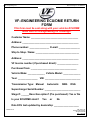
www.vf-engineering.com
MkIV R32 Stage 2 - US MODELS
SUPERCHARGER INSTALLATION
GUIDE FOR VW MKIV R32
STAGE 2 (VFK11-02)
NOT CARB APPROVED
WARNING: DO NOT BEGIN INSTALLATION PRIOR TO
READING THE PRE INSTALL NOTES ON PAGES 2-4
VF ENGINEERING
www.vf-engineering.com
M-F 9:00AM – 5:30PM (PST)
1365 N. Dynamics St. #E, Anaheim CA 92806 • Phone: (714) 528-0066 • Fax: (714) 528-0067
PAGE 1 of 38
P/N: VFM11-02
© 2006 VF Engineering
All rights reserved
Rev 1.10.25.06
www.vf-engineering.com
MkIV R32 Stage 2 - US MODELS
IMPORTANT PRE-INSTALL NOTES:
- SPECIAL INSTALL NOTES
***This installation guide serves as an outline of the steps needed to install your supercharger
system and is not intended to guide a novice through the installation. If you do not have the proper
tools, knowledge and experience to carry out the installation, please seek help from a professional.
**The pictures in this manual are for reference only, and may not match the exact appearance of
your vehicle or parts provided.
**VF-Engineering strongly recommends Bentley Publishers® service manual # VG05 (Golf/Jetta) for
this install**
1)
INSTALLATION OF THIS KIT GREATLY INCREASES THE POWER OUTPUT OF YOUR
STOCK VEHICLE. IT IS IMPERATIVE THAT THE CONDITION OF THE RECIPIENT VEHICLE BE
THOROUGHLY INSPECTED PRIOR TO INSTALLATION, AND THAT BRAKES, TIRES, CLUTCH,
ENGINE MOUNTS, AND SUSPENSION ARE UPGRADED TO HANDLE THE RATED POWER
INCREASE. FAILURE TO DO SO MAY RESULT IN DAMAGE TO YOUR VEHICLE AND MAY
LEAD TO INJURY AND POSSIBLE DEATH. THE USER AND INSTALLER ASSUME ALL RISKS
ARISING FROM THE USE OF THIS PRODUCT. VF-ENGINEERING OR ITS EMPLOYEES ARE
NOT RESPONSIBLE FOR ANY CONSEQUENTIAL LOSSES. THIS SUPERCHARGER SYSTEM
IS INTENDED FOR USE ON HEALTY, WELL MAINTAINED ENGINES. INSTALLATION ON
WORN OUT OR DAMGAGED ENGINES IS NOT RECOMMENEDED AND MAY RESULT IN
DAMAGE TO THE ENGINE AND SUPERCHARGER. VF ENGINEERING IS NOT RESPONSIBLE
FOR ENGINE DAMAGE.
2)
PRIOR TO INSTALLATION, ENSURE YOU HAVE BEEN SUPPLIED WITH THE CORRECT
REPLACEMENT ENGINE ECU CHIP FOR YOUR VEHICLE. YOUR VF-ENGINEERING DEALER
CAN ADVISE YOU OF THE PROPER APPLICATION.
3) BE SURE TO READ INSTUCTIONS COMPLETELY, INCLUDING ALL WARNINGS, NOTES,
TROUBLESHOOTING, AND MAINTAINENCE PRIOR TO INSTALLATION.
4) PLEASE SEE ADDITIONAL PRE-INSTALLATION NOTES ON NEXT PAGE
PAGE 2 of 38
P/N: VFM11-02
© 2006 VF Engineering
All rights reserved
Rev 1.10.25.06
www.vf-engineering.com
MkIV R32 Stage 2 - US MODELS
ECU MODIFICATION REQUIRED
**Please print out the ECU return form (see next page) and include in the package along with your
ECU!
This kit requires ECU modification known as “flashing” which is electronic overwriting of the original engine
management software with new software designed to work in conjunction with your system, and has been
included in the price of your supercharger upgrade. This requires the ECU to be shipped directly to VFEngineering or you can visit your local GIAC dealer for a serial flash of the VF supercharger software. If you
choose to ship the ECU to VF, the ECU modification can usually be turned around in 2-3 working days in
most cases. Please not that any delay does not constitute grounds for product return
If you have a performance flash already in your ECU, you must inform VF-Engineering prior to sending the
ECU.
*****VF Engineering is not responsible for engine or ECU damage due to an improperly installed or
shipped ECU*****
DEALER SERVICE / RETURN TO STOCK
At some point you may take your supercharged car to your VW dealership for a service. It is routine for them
to update the ECU software from time to time and they may not advise you of this beforehand. Therefore it
is imperative that you advise them not to update the ECU or else they may overwrite the supercharger
software installed by VF or authorized dealer. NOTE: If your car is flashed back to stock and you drive
the supercharged car with stock software, engine damage will most likely occur due to inappropriate
fuel and ignition mapping.
If you wish to return your car back to stock, VF advises that the ECU be returned to VF or your local GIAC
dealer for a flash to stock. This is important because VF reprograms the entire ECU and not just the
software file. In effect the ECU is “restored” to its original form.
PAGE 3 of 38
P/N: VFM11-02
© 2006 VF Engineering
All rights reserved
Rev 1.10.25.06
www.vf-engineering.com
MkIV R32 Stage 2 - US MODELS
VF–ENGINEERING ECU/DME RETURN
FORM
This form must be sent along with your vehicles ECU/DME
when sent to VF-Engineering for Flashing!!!
Customer Name: ____________________________________
Address: ___________________________________________
Phone number: _______________ E-mail: ________________
Ship to Shop / Name: _________________________________
Address: ___________________________________________
VF Invoice number (if purchased direct): ________________
Purchased from: ___________________________________
Vehicle Make: _____________ Vehicle Model: _____________
Year: _______________ VIN: ___________________________
Transmission Type: Manual
Automatic
SMG
DSG
Supercharger Serial Number: ___________________________
Stage #: ______Race Gas option? (Pre purchased): Yes or No
Is your ECU/DME stock?
Yes
or
No
Date ECU last updated by dealership: ___________________
PAGE 4 of 38
P/N: VFM11-02
© 2006 VF Engineering
All rights reserved
Rev 1.10.25.06
www.vf-engineering.com
MkIV R32 Stage 2 - US MODELS
DEALER SERVICE / RETURN TO STOCK
At some point you may take your supercharged car to your VW dealership for a service. It is routine for them
to update the ECU software from time to time and they may not advise you of this beforehand. Therefore it
is imperative that you advise them not to update the ECU or else they may overwrite the supercharger
software installed by VF or authorized dealer. NOTE: If your car is flashed back to stock and you drive
the supercharged car with stock software, engine damage will most likely occur due to inappropriate
fuel and ignition mapping. If you wish to return your car back to stock, VF advises that the ECU be
returned to VF or your local GIAC dealer for a flash to stock. This is important because VF reprograms the
entire ECU and not just the software file.
For full performance and continued reliability, please heed the following recommendations:
•
•
•
•
•
•
•
PAGE 5 of 38
Use only premium grade fuel rated at 91 octane or higher (R+M/2)
The compression ratio of the vehicle must be unaltered prior to the installation of this kit
If your engine has been modified in any way, please contact VF Engineering prior to the
installation of this product
Always listen for detonation (pinging) and discontinue hard use (full throttle) until problem is
resolved
Perform an oil and filter change upon completion of this installation and prior to the initial
test drive. All subsequent oil changes should be performed in 3,000 mile intervals using high
quality synthetic motor oil. FAILURE TO MAINTAIN 3,000 MILE INTERVALS CAN LEAD TO
PREMATURE SUPERCHARGER WEAR AND/OR FAILURE.
Before beginning installation, replace all spark plugs that are older than 1 year or 10,000
miles with original heat range plugs as specified by the manufacturer and make sure stock
timing settings are set. DO NOT USE PLATINUM SPARK PLUGS UNLESS THEY ARE
ORIGINAL EQUIPMENT ON YOUR VEHICLE. CHANGE SPARK PLUGS EVERY 15,000-MILES
AND SPARK PLUG WIRES AT LEAST EVERY 50,000-MILES.
The supercharger unit must never be opened or serviced by anyone other than VFEngineering or Vortech.
P/N: VFM11-02
© 2006 VF Engineering
All rights reserved
Rev 1.10.25.06
www.vf-engineering.com
MkIV R32 Stage 2 - US MODELS
Preparation for the installation:
Prior to installation of your VF-Engineering supercharger system, be sure to have the following
maintenance items at hand to replace during the installation:
•
•
•
•
Engine oil and oil filter
Spark plugs
Upper intake manifold gasket
Oil pan sealant
THIS MANUAL PROVIDES INFORMATION ON THE INSTALLATION, MAINTENCE, AND
SERVICE OF THE VF ENGINEERING SUPERCHARGER KIT SPECIFICALLY DESIGNED FOR
THE U.S. SPECIFICATION GTI R32. THIS DOCUMENT MUST BE GIVEN TO THE END USER
BY THE INSTALLER AND THE REGISTRATION FORM (LAST PAGE) MUST BE COMPLETED.
PLEASE CONTACT VF ENGINEERING OR YOUR LOCAL AUTORIZED VF ENGINEERING
DEALER FOR ANY ADDITIONAL INFORMATION REGARDING THE INSTALLATION OF THIS
KIT.
AN UNDERSTANDING OF THE INFORMATION CONTAINED IN THIS MANUAL WILL HELP
NOVICES AS WELL AS EXPERIENCED TECHNICIANS. IF YOU BEGIN INSTALLING THIS
PRODUCT, IT IS ASSUMED THAT YOU HAVE READ THE ACCOMPANYING TERMS AND
CONDITIONS OF USE DOCUMENT AND PRODUCT WARRANTY DOCUMENT.
ALL
INFORMATION, ILLUSTRATIONS AND SPECIFICATIONS CONTAINED HERIN ARE BASED
ON THE LATEST INFORMATION AVAILBALE AT THE TIME OF THIS PUBLICATION. ALL
RIGHTS RESERVED TO MAKE CHANGES AT ANY TIME WITHOUT NOTICE.
PAGE 6 of 38
P/N: VFM11-02
© 2006 VF Engineering
All rights reserved
Rev 1.10.25.06
www.vf-engineering.com
MkIV R32 Stage 2 - US MODELS
INSTALLATION INSTRUCTIONS
1.
2.
Disconnect the ground lead to the battery.
Remove the engine ECU from beneath the windshield cowl, and send it to VF-Engineering for reprogramming. Be sure to package the ECU safely and securely.
PAGE 7 of 38
P/N: VFM11-02
© 2006 VF Engineering
All rights reserved
Rev 1.10.25.06
www.vf-engineering.com
MkIV R32 Stage 2 - US MODELS
3. Disconnect the MAF plug and carefully pry off the vacuum line connected to the back of the intake flexi
duct. Unclip the large spring clamps around the flexi duct that secure it to the throttle body and the MAF.
Disconnect the smog pump hose connected to air box. Remove the MAF and the airbox completely.
The MAF sensor will be used later on in these instructions.
4. Unhook the crankcase vent (1) from the intake duct as shown in the picture below. Remove the small
vacuum line connecting points 2 & 3 below, and use the small rubber cap provided in the kit to cover the
nipple on the plastic hose. The nipple on the manifold is left vacant for the bypass valve vacuum line,
will be covered later. Pivot the crankcase hose 180 degrees counterclockwise at its connection and
leave for later instruction. (***Note: Take caution as this hose is very brittle and can crack easily if it is
flexed excessively!)
PAGE 8 of 38
P/N: VFM11-02
© 2006 VF Engineering
All rights reserved
Rev 1.10.25.06
www.vf-engineering.com
MkIV R32 Stage 2 - US MODELS
5. Remove the other crankcase vent hose from its connection on the back of the manifold, and cap the
nipple on the manifold with the large rubber vacuum cap and clamp supplied. The hose can be left there
or removed, as it is serves no purpose from the factory.
PAGE 9 of 38
P/N: VFM11-02
© 2006 VF Engineering
All rights reserved
Rev 1.10.25.06
www.vf-engineering.com
6.
MkIV R32 Stage 2 - US MODELS
Use the MAF extension harness supplied in the kit to extend the MAF wiring. Cut the harness about 3
inches from the MAF plug. Strip all exposed wires and use the butt connectors provided to connect the
extension harness between the stock MAF wiring and MAF plug. MAF harness routing is covered later
in these instructions. The extension harness provided may contain more wires or different colored wires
than your factory MAF harness. Ensure you make consistent color to color wire connections at each end
of the extension harness.
(**NOTE: Make sure the wire in your MAF extension harness containing an inline resistor capsule is used
inline with the BLACK wire of your MAF wiring. ENGINE DAMAGE MAY OCCUR IF THIS IS NOT
FOLLOWED!)
(**NOTE: Use a heat gun or other non open flame heat source to shrink the ends of the butt connectors
which contain a self sealing glue to form a water tight seal.)
PAGE 10 of 38
P/N: VFM11-02
© 2006 VF Engineering
All rights reserved
Rev 1.10.25.06
www.vf-engineering.com
7.
MkIV R32 Stage 2 - US MODELS
Vehicles fitted with factory installed HID lights are usually fitted with a large windshield washer bottle. This
bottle is replaced with a different shaped bottle as supplied with the kit for non US models only.
The windshield washer bottle is relocated to the area vacated by the air box. Remove the reservoir from its
current location by removing the two retaining nuts. Disconnect the water level sensor and electrical motor’s
electrical plugs. Extend these two plugs using the single harness. Disconnect both of the water connections
(for front and rear washer jets) and extend using the two lengths of washer fluid rubber line provided. Use
the two brackets provided to mount the bottle onto factory mounting points as shown in the picture below.
See the next step for routing instructions.
PAGE 11 of 38
P/N: VFM11-02
© 2006 VF Engineering
All rights reserved
Rev 1.10.25.06
www.vf-engineering.com
8.
MkIV R32 Stage 2 - US MODELS
This step outlines how the MAF and washer bottle extensions are routed towards the opposite side of the
vehicle. The extensions are first routed between the battery and inner fender, then behind the headlight and
under the two panel which must be removed along the top of the radiator support. One of the panels must
be trimmed to allow routing of all extensions harnesses and hoses (see picture below). Tuck the wires and
hoses up to the underside of the front panels and cable tie them were required, keeping in mind that the
wires/hoses may sag in hot conditions, causing them to fall onto the radiator fan blades. The extensions
continue to run across to the side of the engine compartment where the windshield washer reservoir was
previously located.
PAGE 12 of 38
P/N: VFM11-02
© 2006 VF Engineering
All rights reserved
Rev 1.10.25.06
www.vf-engineering.com
9.
MkIV R32 Stage 2 - US MODELS
The power steering return line is extended and re-routed using a custom hose provided in the kit. Unscrew
the power steering reservoir (PSR) from the side engine mount. The PSR bottle will be re-secured to the
side mount later in the instructions.
Tilt the PSR back and remove the clamp securing the hose to the PSR drain spout. Remove the hose and
empty fluid into a clean container, taking caution not to spill any fluid. Cut 6 inches off of the end of the
power steering hose that was connected to the PSR bottle. Run the remaining hose under the chassis leg
and up through a factory hole in the leg. Fit the extension hose provided in the kit in and secure all clamps
after the hose has been positioned so it is not stressed or chaffing other parts. Clean up any spillage and
top off the PSR. (***Note: This extension hose is out of reach after the supercharger unit is fitted and it is
important to ensure you achieve a good clean fit with minimal rub against other sharp edges or parts.)
PAGE 13 of 38
P/N: VFM11-02
© 2006 VF Engineering
All rights reserved
Rev 1.10.25.06
www.vf-engineering.com
MkIV R32 Stage 2 - US MODELS
10.
Relocate the PSR slightly using the relocation bracket supplied in the kit.
11.
Replace the OEM fuel regulator with the unit provided in the kit. Remove the spring clip and gently pry the
stock FPR upwards. (***Caution: Wear goggles and keep a large clean dry cloth around the FPR when
removing, as fuel will leak out.). Fit the new FPR and push down gently until it snaps into place, then refit
the spring retainer clip. Remember to re-fit the vacuum line fitted to the FPR. Reinstall the intake manifold.
PAGE 14 of 38
P/N: VFM11-02
© 2006 VF Engineering
All rights reserved
Rev 1.10.25.06
www.vf-engineering.com
12.
MkIV R32 Stage 2 - US MODELS
Remove the headlights and front bumper, drain the coolant from the vehicle (coolant can be reused if stored
in a clean container) and relocate the auxiliary radiator. Begin by removing both clamps and hoses leading
to the aux. radiator.
PAGE 15 of 38
P/N: VFM11-02
© 2006 VF Engineering
All rights reserved
Rev 1.10.25.06
www.vf-engineering.com
13.
MkIV R32 Stage 2 - US MODELS
Replace the aux. radiator hoses with the new units supplied in the kit and remount the aux. radiator using
the relocation brackets provided. Make a cut out in the splash guard to allow passage of the new hoses to
the aux. radiator. Be sure ample space is given while routing hoses and making the cut out, as these hoses
will expand and move during hard driving. The horns will also need to be relocated (not shown in picture) in
front of the aux radiator using the ‘Y’ bracket included in the kit.
PAGE 16 of 38
P/N: VFM11-02
© 2006 VF Engineering
All rights reserved
Rev 1.10.25.06
www.vf-engineering.com
14.
MkIV R32 Stage 2 - US MODELS
Relocate the smog pump to the lower right hand side of the vehicle, just above the aux. radiator. See picture
below for further instruction.
PAGE 17 of 38
P/N: VFM11-02
© 2006 VF Engineering
All rights reserved
Rev 1.10.25.06
www.vf-engineering.com
MkIV R32 Stage 2 - US MODELS
15.
Mount the intercooler just below the bumper rebar, using the preexisting anchor points and bolts from the
power steering cooler. (Steel pipes shown installed for photography purposes only.) It may be necessary to
trim the plastic radiator ducting behind the intercooler to allow it to sit flush.
16.
Remove the oil pan.
17.
With a pencil or marker, make a mark on the front of the engine block that is:
- “0.750 above the oil pan mating surface of the engine block
- “0.850 to the left of the leftmost side of the bolt highlighted below
PAGE 18 of 38
P/N: VFM11-02
© 2006 VF Engineering
All rights reserved
Rev 1.10.25.06
www.vf-engineering.com
MkIV R32 Stage 2 - US MODELS
(***NOTE: It is important that your hole is not marked directly behind the “rib” of the cast block as
shown from the inside view below.)
18.
Use a center punch to mark the hole, then make a pilot hole with your drill parallel to the ground using your
1/8” drill bit. (note the block sits tipped back at an angle in the engine bay and you will be drilling parallel to
the ground to ensure that the oil drain fitting allows oil to drain into the engine by gravity and does not see
an upward path).
PAGE 19 of 38
P/N: VFM11-02
© 2006 VF Engineering
All rights reserved
Rev 1.10.25.06
www.vf-engineering.com
MkIV R32 Stage 2 - US MODELS
19.
Using a 9/16” drill bit, open the pilot hole by drilling through. Use an abrasive to clean any burrs.
20.
Using the 3/8” NPT thread tap originally supplied with your supercharger kit and tap the hole from the
outside. MAKE SURE YOU NOT TAP PAST 1/3 OF THE LENGTH OF THE THREADED SECTION OF
THE TAP.
PAGE 20 of 38
P/N: VFM11-02
© 2006 VF Engineering
All rights reserved
Rev 1.10.25.06
www.vf-engineering.com
MkIV R32 Stage 2 - US MODELS
21.
Screw the oil drain fitting tight into the block.
22.
Screw the new oil drain connection to the fitting, positioning it as shown in the picture below, and connect
the oil drain line between it and the oil drain of the supercharger. Make sure the oil drain line follows a direct
path to the oil pan, as it relies on gravity to drain the oil. A 5” strip of edge protector is included in the kit to
prevent any damage to oil drain line from rubbing against the frame rail. (see picture on next page).
PAGE 21 of 38
P/N: VFM11-02
© 2006 VF Engineering
All rights reserved
Rev 1.10.25.06
www.vf-engineering.com
MkIV R32 Stage 2 - US MODELS
23.
Clean mating surfaces of oil pan and the bottom of the block as per procedure in the workshop manual.
Ensure that no dirt or debris is left in the oil pan. Refit oil pan using the correct pan sealant paste (available
from aftermarket parts store of OEM parts counter). Re-fill engine oil to correct level.
24.
On some cars, it may be necessary to trim the fuel line support bracket (as show) to allow installation of the
supercharger bracket in the next step.
PAGE 22 of 38
P/N: VFM11-02
© 2006 VF Engineering
All rights reserved
Rev 1.10.25.06
www.vf-engineering.com
MkIV R32 Stage 2 - US MODELS
25.
Use the fuel line relocation bracket supplied in your kit to slightly reposition the fuel lines to allow fitment of
the supercharger.
26.
Remove the tensioner assembly from the cylinder head by removing the three bolts and replace the
tensioner with the supercharger head bracket supplied, reusing the OEM bolts. Torque the bolts to 18 ft. lbs.
Be sure to place the large upper bolt (with washer) through the upper bolt hole (empty hole in picture below)
in the bracket, as it will not be possible to pass the bolt through from behind once installed.
PAGE 23 of 38
P/N: VFM11-02
© 2006 VF Engineering
All rights reserved
Rev 1.10.25.06
www.vf-engineering.com
MkIV R32 Stage 2 - US MODELS
27.
Install the back idler assembly as shown, using the replacement alternator bolts supplied. Be sure to follow
the proper torque specs as shown in your service manual.
28.
Loosely install the supercharge assembly onto the supercharger mounting bracket, using the two bolts
provided in the kit. (12v motor sown in the picture).
PAGE 24 of 38
P/N: VFM11-02
© 2006 VF Engineering
All rights reserved
Rev 1.10.25.06
www.vf-engineering.com
MkIV R32 Stage 2 - US MODELS
29.
Replace the power steering pump pulley with the unit supplied, then install the replacement serpentine belt
included in the kit, following the path shown below. Be sure the belt is aligned on each pulley and is not
offset or de-railed.
30.
Tighten the supercharger mounting bolts slightly, then tension the serpentine belt by inserting a crow bar as
shown below. A twist of 30 degrees between the longest run of the belt is also an adequate way to check
tension. Be careful not to over tension the belt. Tighten the supercharger bolts to approx. 35 ft-lb.
(12v motor shown in picture)
PAGE 25 of 38
P/N: VFM11-02
© 2006 VF Engineering
All rights reserved
Rev 1.10.25.06
www.vf-engineering.com
MkIV R32 Stage 2 - US MODELS
31.
Connect the oil drain line running to the open port on the bottom of the supercharger using the hose clamp
supplied. Be sure the drain line is positioned in such a way that a consistent downward path is made to the
oil pan and that it will not contact any moving parts during use. If necessary, cut the oil drain line to ensure a
direct path is made.
32.
Remove the oil plug on the front of the oil filter housing and replace it with the supercharger oil supply line
(with copper crush washer) supplied in the kit.
PAGE 26 of 38
P/N: VFM11-02
© 2006 VF Engineering
All rights reserved
Rev 1.10.25.06
www.vf-engineering.com
MkIV R32 Stage 2 - US MODELS
33.
Route the oil feed line up to the supercharger oil feed port and connect. Make sure the oil feed line will not
contact any moving parts during vehicle operation (12v motor shown in picture)
34.
Install the supercharger discharge pipe between the supercharger outlet and the intercooler inlet. It may be
necessary to trim the plastic core support, just behind the passenger side (U.S.) headlight to allow fitment of
the pipe.
PAGE 27 of 38
P/N: VFM11-02
© 2006 VF Engineering
All rights reserved
Rev 1.10.25.06
www.vf-engineering.com
PAGE 28 of 38
MkIV R32 Stage 2 - US MODELS
P/N: VFM11-02
© 2006 VF Engineering
All rights reserved
Rev 1.10.25.06
www.vf-engineering.com
35.
MkIV R32 Stage 2 - US MODELS
Remove the MAF sensor from your original airbox, and install the silicon coupler as shown.
PAGE 29 of 38
P/N: VFM11-02
© 2006 VF Engineering
All rights reserved
Rev 1.10.25.06
www.vf-engineering.com
36.
MkIV R32 Stage 2 - US MODELS
Mount (with clamp provided) the air filter (with pre-filter) and cylindrical airbox over the silicon coupler and
onto the correct side of the MAF. Make sure the arrow on the MAF sensor (indicating the direction of airflow)
will be pointing away from the air filter side.
PAGE 30 of 38
P/N: VFM11-02
© 2006 VF Engineering
All rights reserved
Rev 1.10.25.06
www.vf-engineering.com
MkIV R32 Stage 2 - US MODELS
37.
Install the supercharger intake pipe with the MAF sensor, air filter, and pre filter installed on the pipe.
Connect the bypass valve between the supercharger intake and discharge pipes as shown. (**Note: for
1999 and 2000 the MAF should be rotated as shown in the picture below. For 2001-2003 models the MAF
should be rotated in a position such that the flat face of the circuit box on it is vertical). Connect the MAF
plug to the MAF. Use a piece of the edge protector supplied in the kit to prevent the filter from being
damaged against the sharp front panel edge. . Pierce a small 10 mm hole through the end cap of the prefilter and filter. Press fit the air temp sensor through the hole ensuring a tight fit. Cable tie the MAF harness
and air temp sensor harness to ensure they do not interfere with the fan blade.
38.
Route the thin vacuum line on the bypass valve along the inner fender to the empty vacuum nipple you
created on the back of the intake manifold (see step #4) and connect. Secure the line as necessary,
ensuring it does not come into contact with any moving parts.
PAGE 31 of 38
P/N: VFM11-02
© 2006 VF Engineering
All rights reserved
Rev 1.10.25.06
www.vf-engineering.com
39.
MkIV R32 Stage 2 - US MODELS
Cut the crankcase heater element out from the intake flexi duct that connected the MAF to the throttle body.
Connect one end of the heater element to the crankcase vent hose, and use the heater element adaptor to
connect the other end to the port on the side of the supercharger intake tube. Use the extension harness
supplied to extend the heater element plug from the driver’s to the passenger side.
PAGE 32 of 38
P/N: VFM11-02
© 2006 VF Engineering
All rights reserved
Rev 1.10.25.06
www.vf-engineering.com
MkIV R32 Stage 2 - US MODELS
40.
Install the first of three plastic check valves by first locating the vacuum line originating from the driver’s side
(U.S.) of the intake manifold and follow this hose to the Manifold Air Pressure (MAP) sensor mounted on the
body of the car by the passenger side strut tower. Cut the hose and fit the check valve in-line. Make sure the
arrow (or black side of the check valve) faces the manifold.
41.
Install the second and third check valves as shown below. The blue arrows indicate which direction the
black side of the check valves should be facing.
PAGE 33 of 38
P/N: VFM11-02
© 2006 VF Engineering
All rights reserved
Rev 1.10.25.06
www.vf-engineering.com
42.
MkIV R32 Stage 2 - US MODELS
Reconnect the battery, clear any/all DTC’s (engine codes), and start the car. Check for any oil or vacuum
leaks. See the trouble shooting tips on the next page if necessary. Check for any interference issues with all
belts and hoses. Replace the bumper and headlights when you are satisfied with your installation. It may be
necessary to slightly trim the back of the bumper upon reinstallation to allow clearance for the new
intercooler and pipes.
PREVENTITIVE MEASURES
• Check serpentine belt tension after 500 miles. Re-tension if necessary
• Change spark plugs to 1 range cooler for extreme driving and hot climates.
• Clean or replace oil feed nozzle (contains metal mesh screen) with solvent every 6 -12,000
miles.
• Change engine coolant temp senor whilst installing the supercharger kit (often a cause of
fuelling issues on cars of any age).
• A gravity oil drain path for the supercharger drain line is critical for the life of the
supercharger.
• DO NOT use Teflon paste or tape as it blocks the SC oil feed nozzle and voids warranty
• When disconnecting OEM electrical connectors, label them to avoid potential confusion
when re-assembling.
TROUBLE SHOOTING & MAINTENANCE TIPS AFTER INSTALLING SUPERCHARGER KITS
• Injector wiring on older cars can be brittle –check for proper connection
• Contact pins inside injector electrical connectors can bend back if the connector is ever mis-fitted
and lead to intermittent connection and cylinder misfire.
• Loose crankcase vent tube is considered a vacuum leak and will cause poor fuel trimming.
• Loose crankcase vent tube to oil separator is a common cause of vacuum leak.
• Vacuum leak at hoses around silicon couplers may not be visible but is a simple mistake.
• Weak OEM crankcase vent tube (Melts with age) will cause vacuum leak.
• Clean crankcase vent tube and inside of supercharger intake duct every 20K miles and inspect for
leaks and kinks and possibly replace.
SYMPTOMS AND POSSIBLE CAUSES
• Belt squealing at high RPM – Check belt tension
• Hunting idle – major vacuum leak – check silicon couplers especially on throttle body and idle
stabilizer.
• Oil leak – check oil feed banjo – check redundant oil drain plugs on supercharger – check oil drain
line.
• Very erratic idle – verify Mass Air Flow sensor may be fitted oriented in incorrect direction
• MAF signal CEL – check wiring harness extension and electrical continuity in extension harness
***Please read VF product warranty and maintenance/terms of use documents before using this
product.***
PAGE 34 of 38
P/N: VFM11-02
© 2006 VF Engineering
All rights reserved
Rev 1.10.25.06
www.vf-engineering.com
MkIV R32 Stage 2 - US MODELS
VF-ENGINEERING SUPERCHARGER KIT LIMITED WARRANTY
Subject to all the terms, conditions and exclusions set forth in this document, Zurich Engineering,
Inc. (“VF-Engineering”) provides the following warranties to the original purchaser of certain VFEngineering products. For reference purposes, “you” and “your” mean only the original purchaser
of the warranted VF-Engineering product. YOU MUST ALSO READ OWNERS MANUAL.
1.
2.
i.
ii.
iii.
iv.
v.
vi.
vii.
viii.
ix.
x.
xi.
xii.
xiii.
xiv.
xv.
xvi.
xvii.
xviii.
xix.
xx.
xxi.
xxii.
xxiii.
xxiv.
xxv.
The supercharger unit refers to the Vortech Supercharger V-Series unit manufactured by Vortech Engineering Inc.
If you complete and return the Warranty Registration Form along with a copy of Your original receipt within thirty days of Your
purchase of a VF-Engineering supercharger kit, VF-Engineering warrants to you that the V-1, V-2, V-5 and V-9 supercharger in
the kit will be free from defects in materials and/or workmanship in accordance with the Vortech Engineering, Inc. Warranties
Program effective March 1, 2000. The balance of the kit will be free from defects in materials and/or workmanship for oneyear/90 days as specified in sections (4), (5) from the date of your purchase of the kit. If you do not return the Warranty
Registration Form and proof of purchase within thirty days then VF-Engineering warrants that the supercharger in the kit will
be free from defects in materials and/or workmanship for a maximum of one year from the date of purchase of your kit.
3. REQUIREMENTS AND EXCLUSIONS:
You must be the original purchaser.
The supercharger must NOT be modified, disassembled, tampered in any way.
The supercharger drive pulley must not be changed and the original pulley seal must remain intact.
The original Vortech serial number tag must not be removed, altered or replaced.
You must change the engine oil and oil filter at least every 3000 miles using a SH rated oil or synthetic lubricant, regardless of the
vehicle, filter or oil manufacturers recommendations of oil change intervals.
You must remove, inspect, and clean the oil inlet fitting (oil feed nozzle) to the supercharger every 3000 miles.
The conversion must be allowed to ‘break in’ for a period of 300 miles and inspected as per maintenance instructions.
The main serpentine belt must not be excessively tensioned see belt tensioning instructions.
The Supercharger Kit must be maintained according to the minimum service requirements as listed under the maintenance schedule.
Acts of God, normal wear and tear, rust damage, damage to vehicle or engine caused by backfire, engine failure, accident, or
collision.
Improper installation, not following installation instructions provided, or installation by an unskilled person.
Over-speeding the supercharger by any method including under-drive accessory pulleys or larger crank pulley.
Damage resulting from entry of foreign particles.
If the supercharged car is driven after an uncorrected fault has been detected.
Any faults/irregularities are not advised to your vendor.
4. ONE YEAR LIMITED WARRANTY ON VF-ENGINEERING SUPERCHARGER KIT ANCILLARIES AS BELOW:
Mounting brackets and hardware
Supercharger drive pullies and components.
Idler pullies.
Air inlet and discharge systems.
Air valves
GIAC software
5. NINETY DAY LIMITED WARRANTY ON VF-ENGINEERING SUPERCHARGER KIT CONSUMABLES AS BELOW:
Air filters.
Oil feed and oil drain components.
Serpentine belts.
Injectors, regulators and fuel components
WARRANTY COVERAGE FOR THE SUPERCHARGER KIT IS EXCLUDED BUT NOT LIMITED TO THE FOLLOWING CONDITIONS:
6. VF-Engineering does not provide any warranty to You for damages to and/or failure of any non-VF-Engineering component or
equipment on a vehicle, including but not limited to the engine, electrical systems, transmission and differentials;
7. The warranties do not protect You from Acts of God, normal wear and tear, or damage to a vehicle or engine caused by
backfire, collision and or engine failure;
8. These warranties do not cover any costs incurred for towing or downtime of the vehicle, any labor costs to diagnose problems,
to remove or replace the VF-Engineering products, or any damage caused by the use of another company's fittings or pullies.
9. The following non-VF-Engineering occurrences, uses and modifications are considered misuse of the VF-Engineering product
and invalidate all Your VF-Engineering Warranties, including but not limited to:
xxvi. Any disassembly or attempted disassembly of any VF-Engineering assembled parts;
xxvii. Any disassembly or attempted disassembly of the supercharger, volute, gearcase or other components;
xxviii. Damage resulting from ingestion of debris by the supercharger;
xxix. Improper supercharger installation.
xxx. Improper drive pulley/belt combination on supercharger;
xxxi. Excess belt tension on the supercharger belt drive;
xxxii. Over-speeding the supercharger by any method including under-drive accessory pulleys or larger crank pulley.
xxxiii. Restricted or blocked supercharger air intake resulting in excessive negative pressure at the air inlet;
xxxiv. Free revving of the engine with the drive belt driving the supercharger in place;
xxxv. Incomplete fitment of all the parts supplied in the VF-Engineering kit.
xxxvi. Restricted or lack of oil supply to the supercharger;
xxxvii. Improper installation of, or blocked or restricted oil drain line;
xxxviii. Excessive engine crankcase pressures;
xxxix. Dirty or contaminated engine oil;
xl. Removing or defacing the original Vortech serial number tag;
xli. Improper installation, not following installation instructions provided, or installation by an unskilled person;
xlii. If the supercharged car is driven after an uncorrected fault has been detected; or
PAGE 35 of 38
P/N: VFM11-02
© 2006 VF Engineering
All rights reserved
Rev 1.10.25.06
www.vf-engineering.com
MkIV R32 Stage 2 - US MODELS
xliii. Any faults/irregular noises are not advised to your vendor.
10. Power increases with Zurich Engineering, Inc. Supercharger Kits are based on unmodified engines and quoted from results
obtained from dynamometer tests using the Dynojet 248C & 224XLC and no guarantee is given that every car will achieve the
same results as pre-existing conditions may affect results.
EXTENT OF WARRANTY- ADDITIONAL EXCLUSIONS AND LIMITATIONS
11. The duration of any and all warranties is limited to the duration of this express warranty. All incidental and consequential
damages are hereby excluded. Some US states do not allow limitations on how long an implied warranty lasts, or exclusion or
limitations of incidental or consequential damages, so the above limitations or exclusions may not apply to you. This warranty
gives you specific legal rights, and you may have other rights that vary from state to state (USA) only.
12. No warranties of merchantability of fitness for particular purpose, or affirmation of fact, of the warranty, expressed or implied,
other than any available manufacturer’s warranties are extended or granted by VF-Engineering.
DISCLAIMER
13. Motor racing is extremely hazardous, and death may occur. VF-Engineering products have no warranty or representations
made with ability to protect against injury or death. Motor racing, aggressive driving, including driving for any period of time at
full throttle, and car modifications of any kind that facilitate aggressive driving may reduce the useful life of the car and or any
of its wearable parts. Improving the performance of an engine by altering the engine’s computer software may cause the
engine to “work harder” and could result in damage to the car. The user assumes these risks.
REMEDIES
14. Your sole remedy for the above warranties is the repair or replacement of the defective product only, at VF-Engineering’s
discretion.
xliv.
xlv.
xlvi.
xlvii.
xlviii.
xlix.
l.
li.
lii.
liii.
liv.
lv.
lvi.
lvii.
lviii.
15. WARRANTY CLAIM PROCEDURE
If a VF-Engineering product is within the warranty period and You wish to make a claim, please follow the procedure as follows:
Contact VF-Engineering on (+1)714-528-0066 asking for the service department and have the following information available:
Supercharger serial number
Copy of original invoice on which the product was purchased (must be dated and show retail store name);
Year, make, model, vehicle mileage, and engine specifications of the vehicle;
Number of miles on the VF-Engineering product; and
Perceived problem
16. VF-Engineering will then offer suggestions to help you in troubleshooting or will issue a return authorization (R.A.) number to
return the product for warranty evaluation;
17. If you have been issued an R.A. number, you must “safety package” each product, which means You must place the product(s)
within a shipping box strong enough to hold the weight of the product(s) and to maintain its shape during shipping with
adequate packing material so that the product(s) will not hit other product(s), component(s), or the side of the box during
shipping. You want to use a professional company. Clearly mark the R.A. number in large (approximately 2”) alphanumeric
characters in two locations on the outside of the box with a bold marker. Returned items in transit remain the responsibility
until signed for by a member of VF-Engineering shipping dept.
18. INCLUDE IN THE SHIPPING BOX THE FOLLOWING ITEMS:
Serial number if applicable;
Copy of original invoice on which the product was purchased (must be dated and show retail store name);
Year, make, model, vehicle mileage, and engine specifications of the vehicle;
Number of miles on the VF-Engineering product; and
Perceived problem
A copy of the original Three Year Warranty Registration, if applicable;
Return authorization number; and
Address to which the product is to be shipped after inspection.
19. Ship the properly safety packaged and marked box via UPS or other carrier, prepaid and insured for the retail value of the
product being returned to:
VF-Engineering
Service department
1365 North Dynamics Street, Suite E.
Anaheim, CA 92806 USA
R.A. number____________
20. If a VF-Engineering warranty applies, Your product will be repaired or replaced at VF-Engineering’s option and returned to you,
freight prepaid excluding any international shipping, taxes, tariffs, customs and/or duties, etc which must be paid by You), via
UPS/Fedex/DHL ground service. If a VF-Engineering Limited Warranty does not apply, we will advise you of the specific reason
for denial and explain to you the costs involved in repair or replacement of your product. After relaying this information we
will, at your option, either proceed with the repairs as quoted or return your products(s) to you in the condition it/they are in
at the time of inspection of the warranty evaluation by VF-Engineering. Timing is not of the essence in delivery or turn around.
If the warranty does not apply and you do not want VF-Engineering to repair or replace your product, you will be charged the
disassembly and inspection charges for the product and return shipping with insurance by means of UPS COD.
21. This warranty cannot be amended orally or in writing by any VF-Engineering employee, representative or agent, and any
promises inconsistent with this warranty are void and unenforceable against VF-Engineering.
PAGE 36 of 38
P/N: VFM11-02
© 2006 VF Engineering
All rights reserved
Rev 1.10.25.06
www.vf-engineering.com
MkIV R32 Stage 2 - US MODELS
VF-ENGINEERING SUPERCHARGER KIT OWNERS MANUAL
The following information and recommendations are designed to promote years of trouble free
service for your supercharger. Care recommendations have also been outlined for your vehicle and
maintenance of your supercharger kit.
MAINTENANCE INSTRUCTIONS FOR THE SUPERCHARGER KIT and SUPERCHARGER UNIT
Caring for your kit (mandatory procedures)
1. After fitting, the new supercharger kit should be allowed to bed in for a run-in period of 300 miles during which the engine
should not be driven over 4500 rpm.
2. The supercharger kit should be routinely inspected and maintained as below:
ii. Air filters – Use the air filter system provided in your VF-Engineering system.
iii. Air Intake / Air Discharge – Must be in good condition and properly secured. If equipped with flex hose, this must be
Free of damage / leaks.
iv. Belt Tension – Excessive belt tension can lead to supercharger or crankshaft bearing failure. Do not use a non-slipping
or cog-type belt on a supercharger designed to be driven with a serpentine belt. Replacement belts for your
application, are available from VF-Engineering.
v. Air Assist – The air assist system on certain Vortech superchargers must be kept free from kinks and leaks. Spare
parts are available from VF-Engineering.
3. Computer Chips – Use the computer chip or serial flash provided by VF-Engineering for this supercharger system. The use of
an aftermarket chip is not recommended as they would not be calibrated for use with a supercharger and can cause
detonation. VF Engineering supplies a computer chip or serial flash with each kit that is specifically developed and calibrated to
maximize performance.
4. Crankcase Ventilation System – You must use the system provided in your VF-Engineering kit to prevent excessive crank case
pressures and possible engine damage. We recommend you clean or replace this every 6000 miles.
5. Pullies – If your supercharger drive belt comes off it may be due to misalignment of the supercharger pulley cause by
installation issues or movement of the mounting plate. Misalignment can also be caused by over-tightening (and failure) of the
supercharger belt. For years of trouble free operation when used for street applications, we recommend the drive ratios not be
changed from the standard specification.
6. In case of recurring miss-firing or detonation / pinging you should contact your vendor. By following these procedures you will
ensure long term durability and reliability from your conversion.
7. Clean the supercharger oil inlet fitting every 3-6000 miles. When the vehicle is cold, remove the oil inlet fitting at the
supercharger and clean it thoroughly utilizing high pressure air to blow the orifice clean before reinstallation. Do not attempt to
remove the screen/filter inside the oil feed fitting. This oil inlet fitting is designed with a very small orifice, which provides a
mist of oil directly onto the gears. Never use Teflon tape or other sealants on any oil feed line fitting. Do not over-tighten
fittings.
8. Do not use engine oil additives as they may contain solid particulates which can clog the supercharger feed line.
MAINTENANCE OF YOUR SUPERCHARGED VEHICLE
9. Before supercharging your vehicle we recommend you service and inspect your vehicle. Ideally the fault codes should be reset.
This would highlight any existing conditions that may need attention. The condition of consumables, such as oil, filters, spark
plugs, HT (plug wires) leads, ignition coil, and air mass sensor should be inspected and replaced where needed.
10. Never operate your engine at full throttle when the engine is cold. When starting the engine each day, always allow plenty of
time for the oil to reach full operating temperature before running above 2500 RPM. Full operating temperature is generally
achieved only after the engine water temperature has reached the ‘normal’ indicated operating range for 2-3 minutes.
11. Always utilize the highest octane super (premium) unleaded fuel available in your area. Where possible try to use the same
brand of fuel. Where possible do not use fuels sold at low cost service stations and preferably use national brands whenever
possible.
12. After filling up with fuel from a source other than the one you use regularly, carefully listen for engine detonation. If any
detonation is audible, you may have a fuel problem. Cease utilizing heavy-throttle and drive with greater care until the fuel is
consumed. If detonation is still evident, inspect for other causes such as:
i. Faulty fuel pump(s). Check fuel pressure when detonation is occurring.
ii. Dirty injector(s), clogged fuel filter or pinched fuel line.
iii. Faulty spark plug(s) or spark plug wires with too much resistance. Consult your factory vehicle service manual. Most
wires should not exceed 10 Ohms of resistance.
iv. Faulty ignition coil / distributor. Ask VF-Engineering for diagnostic info specific to your vehicle.
v. Cooling system not functioning properly. Check for a faulty thermostat, faulty or improper calibration of the thermostatic
fan switch, water pump belt slippage, a plugged radiator or bad fan clutch.
vi. Dirty air filter / cleaner.
13. Ensure the spark plug gap is correct for a supercharged application.
14. We recommend using manufacturer recommended service components or taking the advice from our dealers specializing in the
different makes of cars.
15. Spark Plugs need to be changed at intervals of 8-10,000 miles or sooner.
16. Spark plug leads (wires) must be checked for condition. When reaching the end of their life, they become hard and must be
replaced as a complete set. Check the condition of your coil pack and test for resistance according to OE spec. Check the
condition of the distributor cap (where applicable) and replace if worn or heavily corroded. Replace rotor every 15,000 miles
and cap every 50,000 or as condition warrant.
17. Engine oil should be changed every 3-5,000 miles. We recommend OE oil. Do not mix different grades of oil qualities.
PAGE 37 of 38
P/N: VFM11-02
© 2006 VF Engineering
All rights reserved
Rev 1.10.25.06
www.vf-engineering.com
MkIV R32 Stage 2 - US MODELS
PRODUCT REGISTRATION FOR WARRANTY.
***THIS DOCUMENT MUST BE RETURNED COMPLETED TO VALIDATE WARRANTY.
Please retain a copy for your records.
Please select one:
( ) 1 YEAR WARRANTY
( ) 3 YEAR WARRANTY
$150 extra at time of purchase
Complete and mail form to:
VF-ENGINEERING
1365 N DYNAMICS STREET, SUITE (E),
ANAHEIM, CA 92806 USA.
www.vf-engineering.com
SUPERCHARGER SERIAL# (see blue tag on supercharger unit):
PRODUCT PURCHASE DATE (also warranty start date):
CUSTOMER NAME :
CUSTOMER ADDRESS :
CUSTOMER TEL# :
Name of dealer / outlet where you purchased your VF-Eng product :
Did you install the supercharger system yourself? Yes / No
VEHICLE KIT FITTED TO :
MAKE / MODEL / YEAR
MILEAGE OF VEHICLE :
CUSTOMER COMMENTS :
VF-Engineering 1365 North Dynamics Street, Suite E, Anaheim, CA 92806 USA Tel (714)585-0066 Fax 714-528-0067
Website: www.vf-engineering.com Hours: M-F 9AM-5PM (PST)
© Zurich Engineering, Inc. Terms may change without notice.
PAGE 38 of 38
P/N: VFM11-02
© 2006 VF Engineering
All rights reserved
Rev 1.10.25.06