1
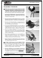
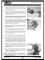
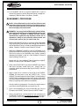
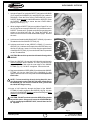
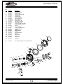
R
O
GYRO SWIVEL OCTOPUS
GYRO
SWIVEL OCTOPUS
SERVICE PROCEDURE
This Service Procedure conveys lists of components and service procedures that
reflect the GYRO Swivel Octopus as it was configured at the time of the writing
(3/24/03).
It also contains Supplemental Information intended to assist the Authorized AERIS
Service Technician who is servicing a GYRO Swivel Octopus that may be configured
with older components.
© 2002 Design 2003
1
Product Service Manual
Doc. No. 12-7527-r01 (3/24/03)
R
O
GYRO SWIVEL OCTOPUS
CONTENTS
TROUBLESHOOTING .................................................................................................................................................................. 2
DISASSEMBLY PROCEDURE .................................................................................................................................................... 4
REASSEMBLY PROCEDURE ..................................................................................................................................................... 6
TUNING AND TESTING ............................................................................................................................................................... 8
PARTS LIST AND EXPLODED VIEW DIAGRAM ...................................................................................................................... 11
SUPPLEMENTAL INFORMATION ............................................................................................................................................ 12
REGULATOR GENERAL PROCEDURES
REFER TO ............................................................................................................................................................... DOC. 12-7508
SPECIFICATIONS
Torques
P/N 30.96725 Swivel Fitting
P/N 30.96726 Swivel Retainer
LP Hose
85 to 95 in-lbs
35 to 45 in-lbs
50 to 60 in-lbs
Opening Effort (IP = 140 psi)
Recommended = 1.5 to 2.0 inches of H2O.
Acceptable
= 1.5 to 2.2 inches of H2O.
TOOLS REQUIRED
Standard Tools
Inch pounds Torque Wrench
5/8” Open End Wrench
3/4” Open End Wrench
11/16” Open End Wrench
1/4” Nut Driver
1/8" Allen Key
3/16" Allen Key
3/4" Deep Wall Socket
1" Deep Wall Socket
Specialty Tools
P/N 30.02302 Christo-Lube MCG111 - 2 oz
P/N 30.03367 Poppet Tool
P/N 30.09315 Intermediate Pressure Gauge
P/N 30.09520 O-ring Tool Kit
P/N TBD
Front Cover Tool
© 2002 Design 2003
2
Product Service Manual
Doc. No. 12-7527-r01 (3/24/03)
R
O
GYRO SWIVEL OCTOPUS
TROUBLE SHOOTING
SYMPTOM
POSSIBLE CAUSE
TREATMENT
1. LEVER ARM (23) bent.
2. Excessive intermediate pressure.
3. Damaged or worn POPPET SEAT
(19).
4. Damaged ORIFICE (18).
5. LOCK NUT (25) overtightened onto
POPPET (20) shaft.
6. WASHER (22) bent or distorted.
7. ORIFICE (18) incorrectly adjusted.
8. POPPET SPRING (21) worn or
weakened.
9. SWIVEL FITTING (15) not sufficiently
tightened into HOUSING (5) Inlet
Tube.
10. Trapped debris.
1. Replace with new.
2. Refer to First Stage Troubleshooting
Chart.
3. Replace with new.
4. Replace with new.
5. Replace with new and readjust.
(Refer to tuning section.)
6. Replace WASHER (22), SPACER
(24), and LOCK NUT (25) with new.
7. Turn in, clockwise, to adjust. (Refer
to tuning section.)
8. Replace with new.
9. Follow correct procedure given in
Reassembly Section to tighten.
10. Remove and clean.
* Excessive inhalation resistance.
1. LOCK NUT (25) overtightened onto
POPPET (20) shaft, causing excessive
POPPET SPRING (21) tension.
2. LOCK NUT (25) insufficiently tightened
onto POPPET (20) shaft, causing
LEVER ARM (23) slack.
3. LEVER ARM (23) bent.
4. ORIFICE (18) incorrectly adjusted.
5. Insufficient intermediate pressure from
First Stage.
1. Replace with new and readjust.
(Refer to tuning section.)
2. Tighten to correct Spring load and
Lever height. (Refer to tuning
section.)
3. Replace with new.
4. Adjust to correct contact. (Refer to
tuning.)
5. Refer to First Stage Troubleshooting
Chart.
* Rattle heard inside Second
Stage.
1. Gravel or sand trapped inside
HOUSING (5).
2. LEVER ARM (23) slack present.
1. Remove and clean.
2. Tighten LOCK NUT (22) onto
POPPET (20) Shaft. (Refer to
tuning section.)
* Little or no airflow when Purge
Button is depressed.
1. FRONT COVER (1/2) not sufficiently
tightened into HOUSING (5).
2. LEVER ARM (23) slack present.
3. LEVER ARM (23) bent.
4. ORIFICE (18) incorrectly adjusted.
1. Tighten COVER RING (2) until
secure.
2. Tighten LOCK NUT (25) onto
POPPET (20) Shaft. (Refer to
tuning section.)
3. Replace with new.
4. Adjust ORIFICE (18) to correct
contact. (Refer to tuning section.)
* Water entering Second Stage.
1. Tear in MOUTHPIECE (9).
2. EXHAUST VALVE (7) distorted or
damaged.
3. DIAPHRAGM (4) distorted or damaged.
4. Debris trapped beneath EXHAUST
VALVE (7).
5. FRONT COVER (1, 2) insufficiently
tightened onto HOUSING (5).
6. Cracked or damaged HOUSING (5).
1. Replace with new.
2. Replace with new.
3. Replace with new.
4. Remove and clean.
5. Tighten until secure and properly
aligned.
6. Replace with new.
* Freeflow or leakage present.
© 2002 Design 2003
3
Product Service Manual
Doc. No. 12-7527-r01 (3/24/03)
R
O
GYRO SWIVEL OCTOPUS
DISASSEMBLY PROCEDURE
NOTE: Be sure to perform the steps outlined in the Initial
Inspection Procedures (Doc. 12-7508) prior to disassembling
the Regulator. Review the Troubleshooting Section to gain
a better idea of which internal parts may be worn, and to
better advise your customer of the service that is needed.
1. Snip the plastic TIE WRAP (8) that holds the MOUTHPIECE (9),
and remove the MOUTHPIECE. Inspect the condition of the
MOUTHPIECE to ensure that it is supple and free of any tears
or corrosion. Discard if found.
Fig. 1
2. Remove the Hose from the Second Stage using an 11/16" Open
End Wrench, while holding the SWIVEL (14) secure with an 3/4"
Open End Wrench (Fig. 1). Use care not to scratch the finish.
3. Remove the Front Cover Assembly (1, 2) using a Front Cover
tool if necessary. DO NOT separate the PURGE BUTTON (1)
and COVER RING (2) unless necessary.
4. Lift out the DIAPHRAGM WASHER (3), then grasp the
DIAPHRAGM (4) by the raised edges of the Center, and lift with
a slight upward twist to remove it. Inspect to ensure it is supple
and free of any tears, corrosion, or distortion. Discard if found.
Fig. 2
5. Remove the SWIVEL RETAINER (11) by turning it counter
clockwise with a 1/4" Allen Key. Remove the SWIVEL RETAINER
O-RING (12) using a brass O-ring Tool and inspect it for any signs
of decay. Discard if found.
6. While holding the HOUSING (5) secure, pull the SWIVEL (14)
straight off the SWIVEL FITTING (15). Use a twisting/pulling
motion to overcome O-ring resistance (Fig. 2). Inspect the
FITTING to ensure that it is free of nicks or burrs.
7. Depress and hold the LEVER ARM (23) while removing the
SWIVEL FITTING (15) in a counter clockwise direction, using a
3/4" modified deep wall socket (Fig. 3).
Fig. 3
CAUTION: DO NOT attempt to remove the SWIVEL FITTING
by inserting any type of tool through the machined openings.
8. Remove the HOUSING INLET O-RING (16) and 2 SWIVEL
FITTING O-RINGS (13) from the SWIVEL FITTING (15) and
inspect for any signs of decay. Discard if found.
9. Remove the ORIFICE (18) from the SWIVEL FITTING (15) by
inserting a 3/16" Allen Key in from the Swivel End of the FITTING
until it engages in the ORIFICE, then turn it clockwise (out) until
it disengages completely from the Threads (Fig. 4).
Use caution to avoid nicking or scratching the delicate knife edge
of the ORIFICE as this is done.
© 2002 Design 2003
4
Fig. 4
Product Service Manual
Doc. No. 12-7527-r01 (3/24/03)
R
O
GYRO SWIVEL OCTOPUS
10. Remove and discard the ORIFICE O-RING (17). Inspect the
ORIFICE (18) carefully with the use of a magnifier to ensure that
it is perfectly free of any scoring or nicks. If found, discard and
DO NOT attempt to reuse it.
11. Hold the POPPET (20) secure with a Poppet Tool and using a
1/4" nut driver inserted through the Mouthpiece opening of the
HOUSING (5), turn the LOCK NUT (25) counterclockwise until no
Threads are showing (Fig. 5).
12. Using the Poppet Tool, push the POPPET (20) inward in the Inlet
Tube of the HOUSING (5), compressing the POPPET SPRING
(21), and carefully remove the LEVER ARM (23) (Fig. 6).
Fig. 5
13. Remove the POPPET (20), POPPET SPRING (21), WASHER
(22), SPACER (24), and LOCK NUT (25) by holding the POPPET
secure with the Poppet Tool and turning the LOCK NUT
counterclockwise using a 1/4" Nut Driver inserted through the
Mouthpiece opening of the HOUSING (5).
14. Examine the SPACER (24) for deterioration. Discard if found.
Discard the LOCK NUT (25) and WASHER (22), and DO NOT
attempt to reuse them.
15. Examine the LEVER ARM (23) and compare with new to ensure
that it is not bent or distorted in any way. Discard if found.
Fig. 6
16. Examine the POPPET SPRING (21) with a magnifier and compare
with new to ensure correct tension and length. Discard if found
to be weakened or corroded.
17. Remove the POPPET SEAT (19) from the POPPET (20) with the
use of a Dental Pick. Discard, and DO NOT attempt to reuse it.
18. Using a small blade Screwdriver or a thin plastic Probe inserted
into the small Slots in the HOUSING (5), carefully press the upper
(or lower) Retaining Tabs of the EXHAUST GUARD (6) (Fig. 7).
Once the EXHAUST GUARD is disengaged, lift it out of the
HOUSING. Repeat to remove the other EXHAUST GUARD.
19. Inspect the overall condition of the HOUSING (5), and the
EXHAUST GUARD (6) to ensure they are free of any stress
cracks or other distortions. Ensure that all threading on the
HOUSING is in good condition. Discard either if any distortion or
damage is found.
20. Using a soft Probe, inspect the condition of the EXHAUST
VALVES (6) to ensure they are supple and free of any tears or
corrosion, and that they seal completely around the Seating
Surface(s) of the HOUSING (5).
NOTE: If the EXHAUST VALVES (6) are in good condition, it
is not necessary to remove them. The HOUSING (5) may be
cleaned with them attached.
© 2002 Design 2003
5
Fig. 7
Product Service Manual
Doc. No. 12-7527-r01 (3/24/03)
R
O
GYRO SWIVEL OCTOPUS
21. If an EXHAUST VALVE (7) requires replacement, it may be
removed by grasping it at the Flange and pulling it straight out,
snipping the Retainer Stem if necessary. Discard.
REASSEMBLY PROCEDURE
NOTE: Prior to Reassembly, inspect all parts, both new and
those that are being reused. Check to ensure that O-rings are
clean and supple, and that every part and component has
been thoroughly cleaned and dried.
WARNING: Use only genuine AERIS parts, subassemblies,
and components whenever assembling AERIS products. DO
NOT attempt to substitute an AERIS part with another
manufacturer’s, regardless of any similarity in shape, size, or
appearance. Doing so may render the product unsafe, and
could result in serious injury or death of the user.
1. Replace the EXHAUST VALVE (7), if removed, into the HOUSING
(5) by gently pulling the Retainer Stem through the HOUSING
until the Retaining Flange is inside the HOUSING and properly
seated. Repeat to install the other EXHAUST VALVE.
2. Replace the EXHAUST GUARD (6) into the HOUSING (5) by
holding the GUARD at a slight angle to insert the lower Retaining
Tabs into the slots in the HOUSING, then carefully pressing
downward and inward on the top of the GUARD to insert the
upper Retaining Tabs (Fig. 8).
Fig. 8
Ensure that all of the Retaining Tabs are properly engaged.
Repeat to install the other EXHAUST GUARD.
3. Place a new POPPET SEAT (19) into the POPPET (20), with the
Side that is perfectly smooth facing out. Ensure that it is
completely seated, flush with the Rim of the POPPET. DO NOT
use adhesive.
4. Apply a light film of Lubricant to each End of the POPPET
SPRING (21) and place it onto the POPPET (20). Fit the
POPPET into the Pronged End of the Poppet Tool and insert the
POPPET Shaft completely through the Inlet Tube of the HOUSING
(5) compressing the SPRING until the Threaded portion of the
Shaft is completely visible inside the HOUSING.
Fig. 9
Hold in position by grasping the Tool with your fingers and the
outer Rim of the HOUSING with your thumb (Fig. 9).
5. Place a new WASHER (22), then the SPACER (24), over the
Threads of the POPPET (20) and onto the POPPET Shaft.
6. Using a 1/4" Nut Driver, turn the LOCK NUT (25) clockwise onto
the POPPET Threads until no Threads are showing beyond the
outer surface of the LOCK NUT (Fig. 10). Remove the tools.
© 2002 Design 2003
6
Fig. 10
Product Service Manual
Doc. No. 12-7527-r01 (3/24/03)
R
O
GYRO SWIVEL OCTOPUS
7. Using the Poppet Tool, push the POPPET (20) into the HOUSING
(5) to expose the WASHER (22) and SPACER (24) inside the
HOUSING. Place the Forks of the LEVER ARM (23) over the
POPPET Shaft between the WASHER and the SPACER. Relax
the POPPET and watch to ensure that the LEVER ARM is
properly oriented (Fig. 11).
8. While holding the POPPET (20) secure with the Poppet Tool, use
the 1/4" Nut Driver to turn the LOCK NUT (25) clockwise onto the
POPPET Threads until 2 Threads are showing beyond the outer
surface of the LOCK NUT (Fig. 12). Relax the POPPET and
watch to ensure that the LEVER ARM stands upright. Remove
the tools.
Fig. 11
9. Lubricate and install the HOUSING INLET O-RING (16) onto the
Threaded end of the SWIVEL FITTING (15).
10. Lubricate and install a new ORIFICE O-RING (17) onto the
ORIFICE (18). Lubricate the Threads of the ORIFICE with a very
thin film of Lubricant. Insert a 3/16" Allen Key through the Barrel
of the SWIVEL FITTING (15) from the Swivel End so it protrudes
out the Threaded End.
CAUTION: Be careful to protect the delicate knife edge of the
ORIFICE.
11. Place the ORIFICE (18) onto the 3/16" Allen Key and thread it
counter clockwise into the SWIVEL FITTING (15) until the Rim
of the ORIFICE is flush with the outer edge of the SWIVEL
FITTING (Fig. 13). DO NOT overtighten. Remove the tool.
Fig. 12
12. Depress and hold the LEVER ARM (23) and thread the SWIVEL
FITTING (15) into the Inlet Tube of the HOUSING (5), then
tighten clockwise with a 3/4" Deep Wall Socket to a torque of 85
to 95 in/lbs.
NOTE: For best sensitivity of touch during Step #13, place
your finger gently on the LOCK NUT (25) while slowly turning
the ORIFICE (18). As soon as contact is made, you will feel
the LOCK NUT begin turning.
Fig. 13
13. Insert a 3/16" Allen Key through the Barrel of the SWIVEL
FITTING (15) until it engages in the ORIFICE (18) (Fig. 14), then
gently turn the ORIFICE clockwise until the Knife Edge is barely
contacting the POPPET SEAT (19).
CAUTION: DO NOT continue to turn the ORIFICE any further
beyond this point. Doing so will cause the LEVER ARM (23)
to drop, damaging the POPPET SEAT, that will then have to
be replaced.
Fig. 14
© 2002 Design 2003
7
Product Service Manual
Doc. No. 12-7527-r01 (3/24/03)
R
O
GYRO SWIVEL OCTOPUS
14. Lubricate and install the 2 SWIVEL FITTING O-RINGS (13) into
the Grooves of the SWIVEL FITTING (15).
NOTE: One end of the SWIVEL (14) is slightly larger than the
other (Fig. 15).
15. Slide the SWIVEL (14), larger end first, straight onto the SWIVEL
FITTING (15). Ensure that it rotates freely through 180 degrees.
16. Lubricate and install the SWIVEL RETAINER O-RING (12) onto
the SWIVEL RETAINER (11).
17. Thread the SWIVEL RETAINER (11) clockwise into the SWIVEL
FITTING (15) and tighten to a torque of 35 to 45 in/lbs.
Fig. 15
18. Place the DIAPHRAGM (4) inside the HOUSING (5) with the
Raised Center facing up, and ensure that it seats flush at the
Base of the Inner Threads.
19. Lay the DIAPHRAGM WASHER (3) on the DIAPHRAGM (4),
and ensure that it positioned evenly.
20. Position the FRONT COVER ASSEMBLY (1, 2) onto the
HOUSING (5), taking care to ensure that it is correctly seated on
the Threads. Hand tighten by turning it clockwise until secure.
Use the Front Cover Tool, if necessary. DO NOT over tighten.
22. Secure the MOUTHPIECE (9) onto the HOUSING (5) with a TIE
WRAP (8), positioning the Locking Tab of the TIE WRAP towards
the lower/left position.
23. Lubricate and replace the O-ring inside the Second Stage
Coupling End of the LP Hose. Install the Hose onto the Second
Stage SWIVEL, and tighten to a torque of 50 to 60 in/lbs with
an 11/16" Open End Wench, while holding the SWIVEL (14)
secure with an 3/4" Open End Wrench (Fig. 16). Use care not to
scratch the finish.
TUNING AND TESTING
Fig. 16
FIRST STAGE TESTING
1. Perform the Leak Detection Test specified in the Initial Inspection
Procedure (Doc. no. 12-7508).
NOTE: Refer to the Trouble Shooting Section (page 3) to
determine the possible cause and treatment of any Air leaks
that may be found.
2. Connect the GYRO Second Stage LP Hose to a Low Pressure
Port of the First Stage. Ensure that all other Ports are sealed with
Port Plugs, with the exception of an additional Low Pressure
Quick Disconnect Hose.
© 2002 Design 2003
8
Product Service Manual
Doc. No. 12-7527-r01 (3/24/03)
R
O
GYRO SWIVEL OCTOPUS
3. Connect a recently calibrated Low Pressure Test Gauge to the
additional Low Pressure Hose, and connect the First Stage to a
pure Air source of 3,000 PSI (206 BAR).
4. Slowly open the valve to pressurize the Regulator, and check the
Test Gauge to ensure that the Intermediate Pressure is set as
recommended in the Specifications for the First Stage used.
NOTE: If the Intermediate Pressure is found to be other than
that specified, refer to that First Stage's Trouble Shooting
Section to determine possible cause and treatment.
TUNING
1. Prior to tuning the GYRO, verify the following:
A. All components are securely installed into the HOUSING (5).
B. The MOUTHPIECE (9) has been cleaned and disinfected.
2. Pressurize the Regulator with a pure Air source of 3,000 PSI (206
BAR) and listen to determine that no airflow is present.
NOTE: An In-Line Adjustment Tool cannot be used to tune
the GYRO while it is pressurized. If adjustment is required,
it must be depressurized to allow the SWIVEL RETAINER (11)
to be removed to gain access to the ORIFICE (18). The LP
Hose does not have to be removed.
CAUTION: To avoid cutting the POPPET SEAT (19) with the
knife edge of the ORIFICE (18), always depress the Purge
Button while turning the ORIFICE in or out.
3. To tune the GYRO, use a 3/16" Allen Key to turn the ORIFICE
(18) (Fig. 17) as necessary to achieve the desired Opening
Effort.
Clockwise turns the ORIFICE out toward the POPPET SEAT
(19), increasing the Opening Effort.
Counter clockwise turns the ORIFICE in, away from the SEAT,
reducing the Opening Effort.
Use the flat side of the Allen Key as a guide to small fractional 1/
12 (30 degree) turns.
CAUTION: Turning the ORIFICE (18) out further than necessary to stop airflow could cut the POPPET SEAT (19).
4. Replace the SWIVEL RETAINER (11), pressurize the Regulator,
and listen carefully for Air flow or leakage.
Fig. 17
© 2002 Design 2003
9
Product Service Manual
Doc. No. 12-7527-r01 (3/24/03)
R
O
GYRO SWIVEL OCTOPUS
5. Hold the Second Stage with the MOUTHPIECE (9) facing directly
down, and gently shake it up and down. Listen carefully for any
rattle that may be present, indicating LEVER ARM (23) slack.
If a rattle is found, perform the following procedure:
A. Purge the Regulator of pressure.
B. Perform Disassembly Procedure Steps #2 through #8 to gain
access to the POPPET (20). DO NOT remove O-rings or discard
parts.
C. Using a 1/4" Nut Driver, turn the LOCK NUT (25) clockwise
further onto the POPPET (20) Shaft with small fractions of a turn,
while holding the POPPET secure using the Poppet Tool.
D. Use the correct method given in Steps #12, #15, and #17
through #20 of the Reassembly Procedure to replace the SWIVEL
after each adjustment, and again determine whether slack is
eliminated.
NOTE: Avoid tightening the LOCK NUT (25) any further than
is necessary to eliminate LEVER ARM (23) slack. It may be
necessary to repeat Step #5 several times to arrive at the
correct setting.
CAUTION: Be careful to avoid over adjusting! If Air flow
returns, replace the LOCK NUT (25) and POPPET SEAT (19)
with new, and start over after rereading the above Procedures.
6. Inhale lightly through the MOUTHPIECE (9) to determine that Air
flows easily and smoothly, without any hesitation or lag.
NOTE: If hesitation or lag is detected, refer to the Trouble
Shooting Section (page 3) to determine possible cause and
treatment.
7. Clean and disinfect the MOUTHPIECE (9) in warm, soapy water
before returning the Swivel Octopus to the customer.
© 2002 Design 2003
10
Product Service Manual
Doc. No. 12-7527-r01 (3/24/03)
R
O
GYRO SWIVEL OCTOPUS
Dia.
No.
Part No.
Description
1c
2c
3b
4b
5c
6c
7b
8c
9c
10c
11c
12b
13b
14c
15c
16c
17a
18c
19a
20c
21c
22a
23c
24b
25a
30.96739
30.96741
30.96381
30.96380
30.96721
30.96727
30.96670
30.91978.07
30.96651.07
30.96738
30.96726
30.9902
30.9013
30.96724
30.96725
30.9906
30.9010
30.96730
30.94340
30.94333
30.95074
30.95117
30.96723
30.94335
30.94336
BUTTON, PURGE
RING, COVER
WASHER, DIAPHRAGM
DIAPHRAGM
HOUSING (BK)
GUARD, EXHAUST
VALVE, EXHAUST
WRAP, TIE (BK)
MOUTHPIECE ( BK)
PROTECTOR, HOSE
RETAINER, SWIVEL
O-RING, SWIVEL RETAINER
O-RING, SWIVEL FITTING
SWIVEL
FITTING, SWIVEL
O-RING, HOUSING INLET
O-RING, ORIFICE
ORIFICE
SEAT, POPPET
POPPET
SPRING, POPPET
WASHER
ARM, LEVER
SPACER
NUT, LOCK
N/S
30.9136
HOSE, 36"
N/S
30.90022
KIT, SERVICE PARTS (includes all Bold items)
1
2
3
6
4
7
5
17
18
20
19
21
8
22
11
12
13
13
14
15
9
24 25
23
16 7
6
10
© 2002 Design 2003
11
Product Service Manual
Doc. No. 12-7527-r01 (3/24/03)
R
O
GYRO SWIVEL OCTOPUS
SUPPLEMENTAL INFORMATION
Due to design enhancements that have been made since the GYRO Octopus was released, the unit being serviced may
not have the same components previously described.
The intent of this Supplemental Information is to assist the AERIS Regulator Service Technician with identification of
previous component parts and provide guidelines for their reuse or replacement.
The exploded view diagram on page 11 can be used as a reference for older units.
Dia. Part No. 4 - DIAPHRAGM
current p/n 30.96380
Compatible with all other parts.
older p/n 30.96729
Replacement with the newer part is not required, but is allowed at your discretion.
Compatible with all other parts.
© 2002 Design 2003
12
Product Service Manual
Doc. No. 12-7527-r01 (3/24/03)