1
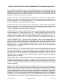
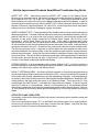
Vehicle Improvement Products
SmartWheel Multiplexed Steering Wheel
Troubleshooting Guide
For use with:
Steering Wheels PC209, PC210 and PC217
Master Control SM209
10 April 2001
Revised 15 August 2001
Vehicle Improvement Products SmartWheel Troubleshooting Guide
It is strongly recommended that this guide be read completely through prior to starting work.
Doing so will speed diagnosing and repairing problems and help prevent damage to the
SmartWheel and related systems.
PRODUCT DESCRIPTION
The SmartWheel Steering Wheel Control System offers control of the horn, headlamp and marker
lamp flash, cruise control, and wiper functions from switches mounted in the steering wheel. The
system consists of two components: the PC209, PC210 or PC217 Steering Wheel and the SM209
Master. Communication between the Steering Wheel and the Master is accomplished via two
wires. The two wires carry a multiplexed communication signal and power for the Steering Wheel
electronics. As each switch is closed, the Steering Wheel generates a unique signal that is
transmitted to the Master. The Master decodes that signal to determine which switch is closed and
operates the corresponding outputs for that function. Some systems include two additional wires to
provide power to backlight the steering wheel switches.
HOW IT WORKS
Functions on the Steering Wheel are either momentary or latching. The HORN, HEADLAMP
FLASH, CRUISE CANCEL, CRUISE RESUME, CRUISE SET, MARKER LAMP FLASH, and
WIPER WASH switches operate in the momentary mode and the corresponding outputs on the
Master are only operated while the switch is pressed. The CRUISE ON/OFF, WIPER OFF, WIPER
HI/LO, and WIPER VARIABLE switches operate in the latching mode and the corresponding
outputs on the master remain actuated until the corresponding CRUISE OFF, or WIPER OFF switch
is pressed or the Ignition input on the Master is turned off. The WIPER HI/LO switch has the
additional feature that initially when the switch is pressed the wipers operate in the low speed mode
and additional operations of the switch cause the wipers to alternate from the high to low speed
modes.
An operational description of each function is as follows:
HORN - The horn switch function on the steering wheel is accomplished using a bar located below
the center of the wheel. If the horn bar is actuated, the Steering Wheel will send the appropriate
signal to the Master to cause the HORN output (J2.1) to be switched to ground while the switch is
pressed. This output is rated at 0.5 Amps max. at 12Vdc.
HEADLAMP FLASH - Operation of this function relies on external switching for the headlamp
function. If +12V is applied to the Headlamp SW input (J11.6), +12V power will be removed from
the Headlamp Power output (J12.2) while this switch is pressed. If J11.6 is low, +12V power will
be applied to the Headlamp Power output (J12.2) while this switch is pressed. The result is that if
the headlamps are turned on, pressing the switch will cause them to go off. In like manner, if the
headlamps are turned off, pressing the switch will cause them to go on. This relay output is rated at
25 Amps max. at 12Vdc. The connector is rated for 20 Amps with the appropriate wire.
1538 15 August 2001
SMWH20010410.DOC
Page 2 of 10
Vehicle Improvement Products SmartWheel Troubleshooting Guide
MARKER LAMP FLASH - Operation of this function relies on external switching for the marker lamp
function. If +12V is applied to the Marker Lamp SW input (J11.12), +12V power will be removed
from the Marker Lamp Power output (J12.3) while this switch is pressed. If J11.12 is low, +12V
power will be applied to the Marker Lamp Power output (J12.3) while this switch is pressed. The
result is that if the marker lamps are turned on, pressing the switch will cause them to go off. In like
manner, if the marker lamps are turned off, pressing the switch will cause them to go on. This relay
output is rated at 25 Amps max. at 12Vdc. The connector is rated for 20 Amps with the appropriate
wire.
CRUISE FUNCTIONS:
Because of the requirement that the cruise control functions be extremely flexible to accommodate
the various brands of cruise control systems, the Smart Wheel System incorporates four individual
relays with the normally-open and normally-closed contacts available to those systems. It also
incorporates a programmable jumper field (JP1) that allows the common (armature) contact of the
Cruise On/Off relay to be connected to one of three sources. If the jumper on JP1 is placed in
position "A", the common contact on the Cruise On/Off relay will be connected to the Cruise
Common input (J11.5). If the jumper on JP1 is placed in position "B", the common contact on the
Cruise On/Off relay will be connected to the Ignition input (J2.4). If the jumper on JP1 is placed in
position "C", the common contact on the Cruise On/Off relay will be connected to ground. In order
to insure proper operation of the cruise control system the technician should consult with the
chassis manufacturer to determine the proper jumper setting prior to installing or replacing a
Master. In accordance with many of the cruise control system manufacturer's requirements, these
relays are "dry-circuit" rated with gold plated contacts rated at 1 Amp max. at 12Vdc.
CRUISE ON - Operation of this switch latches the Cruise On/Off relay in the "on" state. This
causes the source determined by the jumper position on JP1 to be disconnected from the Cruise
On/Off normally-closed (N.C.) output (J11.7) and connected to the Cruise On/Off normally-open
(N.O.) output (J11.8).
CRUISE OFF - Operation of this switch unlatches the Cruise On/Off relay. This causes the source
determined by the jumper position on JP1 to be connected to the Cruise On/Off normally-closed
(N.C.) output (J11.7) and disconnected from the Cruise On/Off normally-open (N.O.) output (J11.8).
In essence, this function is inverse to the Cruise On function. This mode is also entered any time
that +12Vdc power is removed from the Ignition input (J2.4) on the Master.
CRUISE SET - Operation of this switch operates the Cruise Set relay while the switch is pressed.
This causes the Cruise Common input (J11.5) to be disconnected from the Cruise Set normallyclosed (N.C.) output (J11.2) and be connected to the Cruise Set normally-open (N.O.) output
(J11.2).
CRUISE RESUME - Operation of this switch operates the Cruise Resume relay while the switch is
pressed. This causes the Cruise Common input (J11.5) to be disconnected from the Cruise
Resume normally-closed (N.C.) output (J11.4) and be connected to the Cruise Resume normallyopen (N.O.) output (J11.3).
CRUISE CANCEL - Operation of this switch operates the Cruise Resume relay while the switch is
pressed. This causes the Cruise Cancel Common input (J11.9) to be disconnected from the Cruise
Cancel normally-closed (N.C.) output (J11.10) and be connected to the Cruise Cancel normallyopen (N.O.) output (J11.11).
1538 15 August 2001
SMWH20010410.DOC
Page 3 of 10
Vehicle Improvement Products SmartWheel Troubleshooting Guide
WIPER FUNCTIONS:
The wiper control functions are implemented via special control circuitry that is intended to control
two wiper motors and maintain synchronization between these motors on each wipe cycle. For that
reason the faster wiper will pause at the end of each cycle and wait for the slower wiper to complete
its cycle before resuming. The control circuitry utilizes dynamic braking on the wiper motors to
eliminate motor coasting. The connection to each of these motors is made via ten pin connectors
J9 and J10. The output for the wash pump is J5. The +12Vdc power for all wiper functions is
separate from the +12Vdc power for all other functions and is supplied via connector J6. The
ground connection for the wiper motors should be made to the case of each wiper motor - not to the
ground wire coming from the Master (J9.2 & J10.2). The output rating for all wiper relay functions is
25 Amps max. at 12Vdc. The wiper connector contacts are rated at 9 Amps. For applications
requiring greater than 9 Amps, a second row of connector contacts is provided on connectors J9
and J10 for double-wiring. Note: If only one wiper motor is utilized a jumper needs to be placed
between the PARK inputs (J9.3 & J10.3) and connected to the PARK contact for that motor.
WIPER WASH - Operation of this switch activates the wash pump relay while the switch is pressed,
causing the Wash Pump output (J5) to be connected to +12Vdc Wiper Power (J6). In addition, if
none of the latching wiper functions (Wiper Lo/Hi or Wiper Delay) had been previously selected, the
Low Speed Wiper outputs (J9.4 & J10.4) will be connected to +12Vdc Wiper Power (J6) while the
switch is pressed and remain connected for a period of approximately 3 wiper cycles after the
switch is released. If any of the latching wiper functions (Wiper Lo/Hi or Wiper Delay) had been
previously selected, the wipers will continue to run in the selected mode after the wash switch is
released.
WIPER LO/HI - Operation of this switch initially causes the Low Speed Wiper outputs (J9.4 & J10.4)
to be connected to +12Vdc Wiper Power (J6) continuously. If the switch is pressed again the High
Speed Wiper outputs (J9.5 & J10.5) will be connected to +12Vdc Wiper Power (J6) continuously.
Subsequent presses of this switch will cause alternate operation of the wipers in the low or highspeed mode.
WIPER VARIABLE - Operation of this switch initially causes the Low Speed Wiper outputs (J9.4 &
J10.4) to be connected to +12Vdc Wiper Power (J6) for one wipe. If the switch is pressed again
within approximately 30 seconds, the Low Speed Wiper function will be activated again and will
repeat at an interval determined by the time between the last two operations of the switch.
Additional switch operations will shorten the cycle. Activation of any other wiper mode cancels the
variable mode. The effect for the driver is thus: In light rain or mist conditions the driver presses the
switch once when the windshield first needs clearing. When the windshield again requires clearing
the driver presses the button again - setting the time period between subsequent wipes to that
required by current conditions.
WIPER OFF - Operation of this switch causes all operation of the wipers to be canceled. This
mode is also entered any time that +12Vdc power is removed from the Ignition input (J2.4) on the
Master.
HEADLAMPS ON WITH WIPERS - Activation of any wiper function generates a "Headlamps On"
function in the Master that will only be reset by turning off the ignition or by activating then
deactivating the dashboard headlamp switch.
1538 15 August 2001
SMWH20010410.DOC
Page 4 of 10
Vehicle Improvement Products SmartWheel Troubleshooting Guide
SYSTEM INTERCONNECTIONS:
STEERING WHEEL:
Prior to February 2001, most SmartWheels connected to the Master Control via a dual slip-ring
assembly in the steering column. Steering Wheel item numbers PC209x utilize two wires for this
purpose. The yellow wire is the multiplex Signal wire and the brown wire is the multiplex Ground
wire. The controls on these wheels are not backlit.
Since February 2001 steering columns equipped with clock-springs have been widely used in motor
homes. The clock-spring is a device in the steering column that allows continuous electrical
connections through the rotation of the column without sliding contacts. The availability of the
clock-spring has allowed the transmission of sufficient power through the column to backlight the
steering wheel controls. Steering Wheel item numbers PC210x and PC217x utilize four wires for
this purpose. These controls on these wheels are backlit.
Note: Clock-springs can be damaged if they are not handled and installed properly. Before
performing any service involving removing the steering wheel from the column, consult a service
manual for information on maintaining proper centering of the clock-spring. Do not rotate the parts
of a clock-spring except as directed by the appropriate service manual. Failure to follow the proper
procedure can result in the clock-spring being damaged although the damage may not be
immediately apparent.
MASTER:
The SM209 Master is supplied with eight connectors. Connector and pin-out information is included
with the drawings that accompany this guide.
Note: The wiring diagram supplied with this guide is the recommended method of implementing the
SmartWheel system. Individual chassis and coach manufacturers may choose to connect or
implement part or all of the system differently than illustrated here.
GENERAL TIPS:
General handling precautions: Electronics are sensitive to static electrical discharge. Handle them
as little as possible. They are most safe from damage when they are in the package or when they
are installed and connected in the vehicle.
The most common problem with any electrical device is usually related to interconnections: wires
and connectors.
1. If the system does not function properly the first thing to check is that all connectors and
wires are properly installed and fully seated making good contact.
2. If the system is partially functional, i.e., the horn, cruise and lights work but the wipers do
not then the problem is likely not with the multiplex system but with the wiring between the
Master and the wipers or the wiper system itself.
3. If the system is completely nonfunctional, start by checking the power, ground and wiring to
the master and from the Master to the Steering Wheel.
4. If the system functions intermittently, the problem is almost certainly with the wiring in
general or with connections in the steering column.
EQUIPMENT REQUIRED:
• A Digital Volt/Ohm-meter with an audible continuity check.
• A low current (less than 0.5 Amp) 12 Volt test light.
1538 15 August 2001
SMWH20010410.DOC
Page 5 of 10
Vehicle Improvement Products SmartWheel Troubleshooting Guide
INITIAL IN-VEHICLE TESTS:
Proceed with these in the order in which they are listed prior to attempting any other in-vehicle
tests.
•
•
•
•
•
•
The ignition key should be in the “OFF” position until directed otherwise.
Disconnect connectors J5, J9, J10, J11, and J12 from the Master.
Make sure that +12Vdc power is present at J2.5 and J2.6 and connector J6 on the Master.
If not present, check the supply fuses or breakers and wiring.
Measure the DC voltage at J1.1 (Multiplex SIG) on the Master. It should measure in the
range of 7-10 Volts. If it doesn't, check the continuity between J1.2 and chassis ground. If
continuity exists, replace the Master.
Remove the center pad from the Steering Wheel and disconnect the Steering Wheel from
the clock-spring. The center pad can be removed by loosening a 5 mm Allen head screw
that is accessible through a hole on the bottom of the Steering Wheel below the horn bar.
The Allen head screw does not have to be completely removed for the center pad to be
released. It is not necessary to remove the Steering Wheel from the column for these tests.
Measure the DC voltage between the wires in the column that were connected to the yellow
and brown wires on the Steering Wheel. It should also measure in the range of 7-10 Volts.
If it doesn't, check the wiring in the column and to the Master for continuity. If it does,
reconnect the Steering Wheel to the column wiring.
IN-VEHICLE TESTS:
Perform the above Initial In-Vehicle Tests before attempting to perform these tests. Select these by
function if problems are observed with a particular function. Make sure that connectors J5, J9, J10,
J11, and J12 are disconnected from the Master.
HORN TEST - Connect the low current test light between a +12Vdc source and J2.1 (Horn output)
on the Master. Press the HORN bar on the Steering Wheel and the test light should light. If it
doesn't, the Horn output on the Master is damaged (replace the Master).
For the Lamp Flash tests below, the IGNITION Switch on the vehicle should be turned to the
accessory or run position, causing +12Vdc to be present at J2.4 on the Master.
HEADLAMP "OFF" TEST - With no switches pressed on the Steering Wheel and the dash
Headlamp switch off, check for continuity between J12.1 on the Master and J12.2. If continuity
does exist, the headlamp "off" circuitry on the Master is damaged (replace the Master).
HEADLAMP "ON" TEST - While the HEADLAMP FLASH switch on the Steering Wheel is pressed
and the dash Headlamp switch off, check for continuity between J12.1 on the Master and J12.2. If
continuity does not exist, the headlamp "on" circuitry on the Master is damaged (replace the
Master).
MARKER LAMP "OFF" TEST - With no switches pressed on the Steering Wheel and the dash
Headlamp switch off, check for continuity between J12.3 on the Master and J12.4. If continuity
does exist, the marker lamp "off" circuitry on the Master is damaged (replace the Master).
MARKER LAMP "ON" TEST - While the MARKER LAMP FLASH switch on the Steering Wheel is
pressed and the dash Headlamp switch off, check for continuity between J12.3 on the Master and
J12.4. If continuity does not exist, the marker lamp "on" circuitry on the Master is damaged (replace
the Master).
1538 15 August 2001
SMWH20010410.DOC
Page 6 of 10
Vehicle Improvement Products SmartWheel Troubleshooting Guide
For the CRUISE and WIPER tests below, the IGNITION Switch on the vehicle should be turned to
the accessory or run position, causing +12Vdc to be present at J2.4 on the Master. Note the
position of the jumper on the configuration header JP1 so that unit can be returned to that
configuration after the tests have been completed. After that position is noted, place the jumper in
position "A" so that Cruise Common is the source.
CRUISE "ON" TEST - Momentarily press the CRUISE "ON" switch on the Steering Wheel.
Because this is a latching function, the function should be active after the switch is released. Check
for continuity between J11.5 on the Master and J11.8. If continuity does not exist, the cruise "on"
circuitry on the Master is damaged (replace the Master).
CRUISE "OFF" TEST - Momentarily press the CRUISE "OFF" switch on the Steering Wheel.
Because this is a latching function, the function should be active after the switch is released. Check
for continuity between J11.5 on the Master and J11.7. If continuity does not exist, the cruise "off"
circuitry on the Master is damaged (replace the Master).
CRUISE "SET" TEST - With the CRUISE "SET" switch on the Steering Wheel not pressed check for
continuity between J11.5 on the Master and J11.2. If continuity does not exist, the cruise "set"
circuitry on the Master is damaged (replace the Master). While the CRUISE "SET" switch on the
Steering Wheel is pressed check for continuity between J11.5 on the Master and J11.1. If
continuity does not exist, the cruise "set" circuitry on the Master is damaged (replace the Master).
CRUISE "RESUME" TEST - With the CRUISE "RESUME" switch on the Steering Wheel not
pressed check for continuity between J11.5 on the Master and J11.4. If continuity does not exist,
the cruise "resume" circuitry on the Master is damaged (replace the Master). While the CRUISE
"RESUME" switch on the Steering Wheel is pressed check for continuity between J11.5 on the
Master and J11.3. If continuity does not exist, the cruise "resume" circuitry on the Master is
damaged (replace the Master).
CRUISE "CANCEL" TEST - With the CRUISE "CANCEL" switch on the Steering Wheel not pressed
check for continuity between J11.9 on the Master and J11.10. If continuity does not exist, the
cruise "resume" circuitry on the Master is damaged (replace the Master). While the CRUISE
"CANCEL" switch on the Steering Wheel is pressed check for continuity between J11.9 on the
Master and J11.11. If continuity does not exist, the cruise "cancel" circuitry on the Master is
damaged (replace the Master).
WIPER "WASH" TEST - While the WIPER "WASH" switch on the Steering Wheel is pressed, check
for the presence of +12Vdc at J5. If +12Vdc is not present at J5, the wash pump output circuitry on
the Master is damaged (replace the Master). In addition, check for the presence of +12Vdc at J9.4
and J10.4. If +12Vdc is not present, the low speed wiper wash circuitry on the Master is damaged
(replace the Master).
WIPER "LO/HI" TEST - Momentarily press the WIPER "LO/HI" switch on the Steering Wheel.
Because this is a latching function, the function should remain active after the switch is released.
Check for the presence of +12Vdc at J9.4 and J10.4 on the Master. If +12Vdc is not present, the
continuous low speed wiper circuitry on the Master is damaged (replace the Master). Momentarily
press the WIPER "LO/HI" switch again and check for the presence of +12Vdc at J9.5 and J10.5 on
the Master. If +12Vdc is not present, the continuous high-speed wiper circuitry on the Master is
damaged (replace the Master). Subsequent presses of this switch will cause alternate presence of
+12Vdc at the low speed (J9.4 and J10.4) or high-speed (J9.5 and J10.5) outputs on the Master.
1538 15 August 2001
SMWH20010410.DOC
Page 7 of 10
Vehicle Improvement Products SmartWheel Troubleshooting Guide
WIPER "OFF" TEST - Momentarily press the WIPER "OFF" switch on the Steering Wheel.
Because this is a latching function, the function should be active after the switch is released. Check
for no output at J9.4, J9.5, J10.4, and J10.5 on the Master. If +12Vdc power is present on any of
these output pins, the wiper off circuitry on the Master is damaged (replace the Master). In order to
check the dynamic braking circuitry after the WIPER "OFF" switch is pressed, check for continuity
between J9.2 and J9.4 and also between J10.2 and J10.4. If continuity does not exist, the dynamic
braking circuitry on the Master is damaged (replace the Master).
WIPER "VARIABLE" TEST – Thorough testing of the variable function is fairly complex and requires
additional equipment. If all other functional wiper tests have been completed successfully, the only
practical field test is to re-connect the wiper motor(s) and verify correct function operationally.
Operation of this switch initially causes the Low Speed Wiper outputs (J9.4 & J10.4) to be
connected to +12Vdc Wiper Power (J6) for one wipe. If the switch is pressed again within
approximately 30 seconds, the Low Speed Wiper function will be activated again and will repeat at
an interval determined by the time between the last two operations of the switch. Additional switch
operations will shorten the cycle. Activation of any other wiper mode cancels the variable mode.
The effect for the driver is thus: In light rain or mist conditions the driver presses the switch once
when the windshield first needs clearing. When the windshield again requires clearing the driver
presses the button again - setting the time period between subsequent wipes to that required by
current conditions. If the driver does not press the switch again within approximately 30 seconds of
the initial press, there will be only one wipe. If the function is not as described, the variable delay
circuitry on the Master is damaged (replace the Master).
STEERING WHEEL – If as described above in the Initial In-Vehicle Tests 7 – 10 Volts is present on
the yellow and brown wires on the Steering Wheel and the Master is not responding to any button
presses in the above tests, replace the Steering Wheel.
BACKLIT STEERING WHEEL – On Steering Wheels mounted on clockspring-equipped steering
columns the Steering Wheel switch pads are backlit by LEDs. It may be necessary to look directly
at the switch pads through cupped hands to see the backlighting in daylight. If the backlighting is
not working, remove the center pad from the Steering Wheel as described above. Measure the DC
voltage between the black and green wires on the Steering Wheel. There should be 12 Volts
present when the IGNITION is on. If not check the 3 Amp fuse on the Master. If the fuse is good,
check for 12 Volts on J1.4 on the Master. If there is 12 Volts present at J1.4 on the Master and not
at the steering wheel then check the wiring between the master and the Steering Wheel. If there is
12 Volts present at the Steering Wheel and the backlighting is not working, replace the Steering
Wheel.
AFTER TESTS ARE COMPLETED:
If necessary, reconnect the Steering Wheel to the column connector(s) and re-attach the center pad
with the Allen bolt.
If the cruise configuration jumper “JP1” on the Master was moved restore it to its original position.
Re-connect all connectors that may have been removed from the Master. Note that the wiper
connectors J9 and J10 can be interchanged without harm.
1538 15 August 2001
SMWH20010410.DOC
Page 8 of 10
2