1
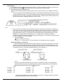
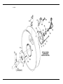
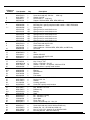
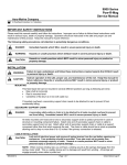
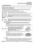
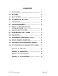
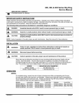
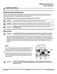
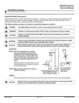
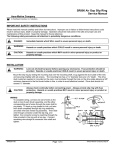
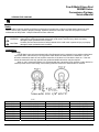
Pow-R-Matic® Hose Reel
2000MD Series
Convenience Package
Service Manual
AERO-MOTIVE COMPANY
A Woodhead Industries, Inc. Subsidiary
Safety
Please read this manual carefully and follow its instructions. Improper use or failure to follow these instructions could
result in serious injury, death or property damage. Operators should be instructed in the safe and proper use and
maintenance of this product. Keep this manual for future reference.
The following safety precautions call attention to potentially dangerous conditions.
Warnings are used when hazards exist which could result in serious injury, death or property
WARNING:
damage if proper precautions are not taken.
Cautions are used as reminders of safety hazards which could result in personal injury or property
CAUTION:
damage if proper precautions are not taken.
Installation
Mounting
Pow-R-Matic hose reels are equipped with a fixed base and can be mounted in any position--either base
up or base down, wall mounted, or in any position which allows the main shaft to be horizontal. The reel
should be mounted so that it is level, and the center line of the drum is in line with the hose run. If the reel
cannot be mounted in this way, special hose guides and additional tension may be required.
When a reel is mounted overhead, it is recommended that a secondary chain, bracket or other device be
used to prevent the reel from falling if the mounting bolts are removed or loosened due to vibration.
Model
2053 - 2050
2343 - 2340
2373 - 2370
2576 & 2776
2577 & 2777
2578 & 2778
2579 & 2779
2570 & 2770
SM5470-02A
Dim. A
11.25 (285.8)
15.25 (387.4)
15.25 (387.4)
11.25 (285.2)
11.25 (285.2)
11.25 (285.2)
11.25 (285.2)
11.25 (285.2)
Dim B.
9.00 (228.6)
9.00 (228.6)
9.00 (228.6)
8.25 (209.6)
10.44 (265.2)
12.56 (319.0)
14.75 (374.7)
16.94 (430.3)
Page 1 of 8
Dim. C
9.25 (247.7)
9.25 (247.7)
10.75 (273.1)
11.38 (289.1)
11.38 (289.1)
11.38 (289.1)
11.38 (289.1)
11.38 (289.1)
©Apr-03
Pretensioning
Pow-R-Matic® reels are not pretensioned at the factory. It will be necessary to apply set up turns to the
motor to pretension the reel (in much the same way as a window shade is pretensioned).
A. Determining number of pretension turns.
There are two methods of determining the proper number of pretension turns to be applied to the hose
reel.
1. There is an instruction plate located on the flange. This instruction plate states the maximum number
of turns available in the reel. The instruction plate also has a space for the number of set up turns to
pretension the reel. (If this box is blank, go to Step 2, below.) Using the figure obtained from the set
up turn box, proceed to “Applying Pretension - Set Up Turns”.
2. If the set up turn box is blank, use the following procedure: Determine the number of revolutions of
the hose drum to wrap up the working hose. Subtract the number of turns required, to wrap the hose
on the drum, from the maximum turns available (obtained from the instruction plate on the flange).
Divide the answer by two (2). This will give you the average number of pretensioning set up turns.
EXAMPLE: A reel has 100 feet of working hose. You determine by counting the number of
revolutions that the drum rotates 20 times to wrap the working hose. The instruction plate states that
there are a maximum of 50 turns available.
50 turns available
-20 turns to wrap hose on drum
30 turns ÷ 2 = 15 set up turns. This reel would have 15 pretension set up turns applied.
Applying pretension - set up turns
Prior to terminating hose, follow the prescribed steps below. Make sure that there are no twists
or kinks in the hose, and that all hose is on the reel. NOTE: When reversing winding the reel, you
will hear a clicking sound as the springs disengage from the drive hubs. This is a safety device and
no damage will result. All springs will engage when the hose is pulled out.
10 or 50 =
12 or 52 =
13 or 53 =
15 or 55 =
16 or 56 =
1. Mill duty reels and Pow-R-Matic hose reels, with a convenience package, are equipped with
external tensioning devices, the following method of pretensioning can be used. Find the fifth
and sixth digits of the model number in the chart below.
Factor
Factor
Factor
1.0
17 or 57 = 1.7
26 or 66 = 2.6
1.2
20 or 60 = 2.0
30 or 70 = 3.0
1.3
22 or 62 = 2.2
36 or 76 = 3.6
1.5
23 or 63 = 2.3
40 or 80 = 4.0
1.6
25 or 65 = 2.5
45 or 85 = 4.5
Multiply the appropriate factor by the number of set up turns. The figure obtained is what the
counter reading should be on the motor end plate.
SM5470-02A
Page 2 of 8
©Apr-03
After the hose has been properly anchored, as described in “Hose Anchoring”, the pretension,
set up turns are applied as follows: Make sure the counter is set at 0000, then using a wrench, or
bar, the shaft extension located at the rear of the motor is rotated until the above figure is
reached. The number of turns are recorded on a counter. The counter records whole turns and
tenths of a turn (much the same as an odometer in a car). See Figure 3.
Alternate method of pretensioning
Pull the hose out far enough to allow one full wrap of hose to be thrown back over the drum.
Place a bar through the holes located near the edge of the flanges to prevent the drum from
turning while the hose is placed on the reel.
This placed one pretension set up turn on the reel. Repeat the above procedure until the
proper number of set up turns have been applied.
Hose anchoring
Before terminating or anchoring hoses, always pull all of the hose off from the reel (against the
CAUTION:
spring tension) to be sure that there are enough turns in the reel, for the hose travel. If you reach
the end of the spring before all hose is removed form the drum, stop and remove pretension turns.
Remove any twists or kinks from the hose, while hose is extended.
Failure to comply with these procedures can result in damage to the reel and hose.
A. Pull the working hose (against the tension of the reel) to the connection point, with adequate slack to
make the connections. Place a bar through the holes near the edge of the flanges to relieve the tension
on the hose, and hold the pretension turns on the reel. Make sure there are no twists or kinks in the
hose.
B. When anchoring the hose, a hose grip should be incorporated in such a way as to allow a slack in the
hose prior to entering the connection points.
SM5470-02A
Page 3 of 8
©Apr-03
CAUTION:
Never apply so many turns that the springs are worked to the end of their travel. Always leave
several turns between the end of the spring and the position of the drum when the drum is fully
extended. If the spring reaches the end of its travel before satisfactory tension is achieved, consult
the factory.
Service
CAUTION:
Before performing any service, always remove all reel spring tension. Failure to comply with these
practices can result in injury to personnel or damage to equipment.
Be sure that all spring tension has been removed from reel before servicing spring motor.
A. Spring motor replacement
1. Be sure spring motor is adequately supported. Lifting hooks have been provided for this.
2. Remove four bolts (8) and rear motor support bracket (4), when applicable, hose (5).
3. Slide the spring motor back to disengage from the drive shaft.
4. Read the enclosed spring motor instructions carefully before attempting spring replacement.
5. To replace spring motor, reverse the above procedure.
6. After spring motor is reinstalled, repeat the spring tensioning procedure in the pretensioning section.
Always include model number and serial number when ordering parts or information.
SM5470-02A
Page 4 of 8
©Apr-03
Replacement Parts
SM5470-02A
Page 5 of 8
©Apr-03
SM5470-02A
Page 6 of 8
©Apr-03
Reference
Number
1
2
3
4
5
6
7 **
8
9
10
11
12
13
14
15
16
17
18
19
20
21
22 **
23
24
25
26
27
28
29
30 **
31 **
32
33
34 **
35
36 **
37 **
38
39
40
41
42
43
44
45
SM5470-02A
Part Number
00032P0105
00032P0103
00101P0021
C22020312
5987500000
5987400001
4083200000 *
4395300000 *
4391200000 *
4391201305
4391201405
4391201505
4391201605
4391201705
4391201805
4391201905
4391201005
00032P0103
5982700000
5987800000
4068000000
4082500000
00380P0003
C01010222
00032P0112
C22020312
40149xxxxx
4077300002
000029P0108
00101P0030
4082200000 *
4011900000
4000500000
4080600000
6116700000
4081600000
00030P0211
00151P0025
00101P0015
6111500000
00158P0002
4372300000 *
00751P0011
00581P0075
00376P0120
4370300000
00230P0133
00230P0151
3743600000
00209P0023
00034P0013
00101P0016
00030P0117
00126P0050
00151P0020
4026600000
Qty.
3
1
8
1
1
1
2
2
1
AR
AR
AR
AR
AR
AR
AR
AR
4
1
1
1
1
1
1
1
1
1
1
4
23
1
1
1
1
1
2
4
4
4
1
AR
1
1
2
2
1
1
1
1
4
4
4
4
4
11
4
Description
Screw hex head cap 3/8-16x7/8
Screw hex head cap 3/8-16x1
2300 only
Washer lock 3/8”
Nut hex 3/8-16 2300 only
Support 2300 and MD2, MD3, MD4, MD5 only
Support - others
Mounting foot - specify complete model number -- 2000, 2300 series
Mounting foot - specify complete model number -- 2500, 2700 series
Spring motor
Spring motor for model 2xx3-xx-xxx
Spring motor for model 2xx4-xx-xxx
Spring motor for model 2xx5-xx-xxx
Spring motor for model 2xx6-xx-xxx
Spring motor for model 2xx7-xx-xxx
Spring motor for model 2xx8-xx-xxx
Spring motor for model 2xx9-xx-xxx
Spring motor for model 2xx0-xx-xxx
Screw hex head cap 3/8-16x1
Stand weldment - others
Stand weldment - 2300 and MD2, MD3, MD4, and MD5 only
Set screw
Spacer, sprocket
Idler
Washer 3/8x.065
Screw hex head cap 3/8-16x2
Nut hex 3/8-16
Main shaft - specify model number
Key 1/4 sq. X 7/8 l
Screw 1/4-20x5/8 - Soc HD
Washer 1/4x.062 - 15 required - 2500 and 2700
Sprocket, driven - specify model number
Spacer
Bearing
Sprocket hub
Retainer
Felt washer
Screw hex head cap #10 - 24x3/8
Nut hex #10 - 24
Washer
Housing, sprocket
Chain #40 - specify model number
Sprocket, driving - specify model number
Key, Woodruf 1/4 x 3/4
Retainer ring
Bearing
Shaft
Pin .375 dia x 175 long
Pin .218 dia x 1.75
Name plate
Rivet, dome 1/8”
Screw, hex head cap 1/2 - 12x1-1/4
Washer 1/2 lock -- 2000 and 2300 only
Screw hex head cap 1/4x20 2000 and 2300 only
Washer flat 1/4” x 20 2000 and 2300 only
Nut 1/4” x 20 x 5/8 - quantity 15 on 2000 and 2300
Mounting bracket 2000 and 2300 only
Page 7 of 8
©Apr-03
46
47
48
49
56
57
58
59
60
61
62
63
64
65 **
66
67
68
69
74 **
75
76
85
86
87
88
89
00030P0111
2R
3R
4928500003
6079300000
6079400000
00669P0035
00669P0054
00669P0030
2F-RE, YE
3F-RE, YE
4080500001
00101P0031
00030P0110
00230P0105
4399000001
4399000002
4399000003
6150300000 *
4920100000 *
5947900000
00011P0019
00666P0032
00666P0038
H72410001
H72410002
H72410003
H72410005
00669P0010
00669P0064
00669P0041
5953500000
5953800000
M53320034
00101P0030
00030P0115
4000500000
4014300034
00101P0030
00053P0504
00053P0231
00035P0014
00151P0075
00101P0014
6110500000
Aero-Motive Company
A Woodhead Industries Inc. Subsidiary
PO Box 2678
Kalamazoo, MI 49003-2678
USA
(269) 337 7700 / (800) 999 8559
FAX: (800) 333 6119
www.aeromotive.com
[email protected]
SM5470-02A
11
1
1
1
2
2
2
2
2
1
1
1
15
4
2
1
1
1
AR
AR
1
1
1
1
1
1
1
1
2
2
3
1
1
1
2
2
1
6
6
1
2
2
2
2
2
Screw hex head cap 1/4 - 20x5/8 - quantity 15 on 2000 and 2300
Guide rail assembly 2000 - 40729
Guide rail assembly 2300 - 4” wide spool (40729-1)
Guide rail assembly 2300 - 7” wide spool
Tie bar with 4 inch wide spool
Tie bar with 7 inch wide spool
Reducer -- 2xxx-xx-002 through -004, -014
Reducer -- 2xxx-xx-006, -016
Reducer -- 2xxx-xx-012, -013
Roller guide -- 41826-1
Roller guide -- 43752
End plate
Washer 1/4x.062 lock -- 6 for REF#80 junciton box
Screw, hex head 1/4-20 x 3/4
Pin .094 dia x .375 long
Spool - 5” width, 24” dia no ratchet
Spool - 5” width, 24” dia for ratchet CW rotation
Spool - 5” width, 24” dia for ratchet CCW rotation
Hose clamp assembly - specify hose size
Hose clamp assembly - specify hose size
Collar, locking
Screw, set
Swivel -- 2xxx-xx-002 through -004
Swivel -- 2xxx-xx-006, -008
Swivel -- 2xxx-xx-012, -013
Swivel -- 2xxx-xx-014
Swivel -- 2xxx-xx-016
Swivel -- 2xxx-xx-018
Reducer -- 2xxx-xx-002
Reducer -- 2xxx-xx-003
Reducer -- 2xxx-xx-012
Drive fork -- 2xxx-xx-002 through -004, -012 through -014
Drive fork -- 2xxx-xx-006, -008
Drive fork -- 2xxx-xx-016, -018
Washer, lock 1/4x.062
Screw
Bearing
Bolt tie - 4” spool
Lock washer 1/4x.062
Set screw 3/8-16 x 1-1/2 - models 2xxx-50, 52, 53, 55
Set screw #10 - 24x1/4 - models 2xxx-56-85
Bolt, carriage 5/16-18x1-3/4
Nut hex 5/16-18
Washer lock 5/16
Spacers
Woodhead Connectivity LTD.
A Woodhead Industries Inc. Subsidiary
Factory No. 9
Rassau Industrial Estate
Ebbw Vale Gwent NP23 5SD
United Kingdom
44-1495-356300
FAX: 44-1495-356301
[email protected]
Woodhead Asia PTE LTD.
A Woodhead Industries Inc. Subsidiary
No. 4 Toh Tuck Link
Level 3 Mezzanine
Markono Logisitics Bldg.
Singapore 596226
65-6-261-6533
FAX: 65-6-261-3588
[email protected]
Page 8 of 8
Woodhead Canada LTD.
A Woodhead Industries Inc. Subsidiary
1090 Brevik Place
Mississauga Ontario
L4W 3Y5 Canada
(905) 624-1079
FAX: (905) 624-9151
www.woodhead.ca
©Apr-03