1
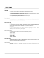
Patient Monitor
BP-S510
Operation Manual
Part Number: A7072 Rev.1 (1731064B)
Revised Date: 04/2006
Printed in Korea
Copyright © 2005-2006 All rights reserved.
Directive
z
z
z
z
Copyright law allows no part of this instruction manual to be reproduced without
permission.
The content of this manual are subject to change without notice.
The contents of this manual should be correct. If, for some reason, there are any
questionable points, please do not hesitate to contact our service center.
The manual will be replaced if any pages are missing or collation is incorrect.
Warranty
z
z
z
z
Please contact your local distributor about the warranty period.
Device failure or damage related to the following situations during the guarantee period
is not covered by this warranty:
z
Installation, transfer installation, maintenance and repairs by any person other than
an authorized Colin Medical Technology employee or technician specified by Colin
Medical Technology.
z
Damage sustained to the Colin Medical Technology product(s) caused by
product(s) from another company excluding products delivered by Colin Medical
Technology.
z
Damage – caused by mishandling and/or misuse – is the responsibility of the user.
z
Maintenance and repairs utilizing maintenance components that are not specified
by Colin Medical Technology.
z
Device modifications or use of accessories not recommended by Colin Medical
Technology.
z
Damage caused by accidents or natural disasters (earthquakes, flooding, etc.).
z
Damage resulting from usage where caution statements and operating instructions
shown in this manual have not been followed.
z
Damage due to neglect of specified maintenance checks.
This warranty only covers the hardware of the BP-S510. The warranty does not cover the
following selections:
z
Whatever damage or loss results from the attachment of accessories or their
operation.
z
In the event of a defect in the product, contact our sales outlet or EU representative
as noted on the back cover.
The BP-S510 conforms to the EMC standard IEC60601-1-2.
Note that mobile phones should not be used in the vicinity of the BP-S510.
Note, however, any device not complying to the EMC standard that is used with the BP-S510
renders the BP-S510 as non-compliable to the EMC standard.
Trademark
Product brand names shown in this manual are likely to be the trademark or registered
trademark of the company concerned.
CONTENTS
CONTENTS....................................................................................................................................................i
SAFETY INFORMATION ..............................................................................................................................1
General Safety Information ...................................................................................................................1
Warning .................................................................................................................................................1
Cautions ................................................................................................................................................3
INTRODUCTION ...........................................................................................................................................5
Intended Use for the BP-S510 ..............................................................................................................5
About This Manual.................................................................................................................................5
Identifying the BP-S510 monitor Configurations ...................................................................................5
Features for the BP-S510......................................................................................................................6
DESCRIPTION OF THE MONITOR..............................................................................................................7
Front Panel Components ......................................................................................................................7
Rear Panel Components .......................................................................................................................9
Left Panel Components .......................................................................................................................10
Right Panel Components .................................................................................................................... 11
Displays ...............................................................................................................................................13
SETTING UP THE MONITOR.....................................................................................................................17
Unpacking and Inspection ...................................................................................................................17
List of Components..............................................................................................................................18
Power Cable Connections...................................................................................................................21
Measurement Cable Connections .......................................................................................................22
BATTERY OPERATION..............................................................................................................................23
Operating the Monitor on Battery Power.............................................................................................23
Battery Status Indication......................................................................................................................24
Charging a Low Battery.......................................................................................................................24
USING THE MONITOR ...............................................................................................................................25
Turning on the Monitor ........................................................................................................................25
Setting Date and Time.........................................................................................................................27
Setting Basic Setup Parameters .........................................................................................................28
ALARMS AND LIMITS................................................................................................................................33
General................................................................................................................................................33
Alarm Priority and Messages ..............................................................................................................34
Visual Alarm Indication ........................................................................................................................38
Audible Alarm Indication......................................................................................................................38
Verifying Visual and Audible Alarm Indication .....................................................................................38
Changing Alarm Limits.........................................................................................................................39
Audible Alarm Silence .........................................................................................................................43
Audible Alarm Suspend .......................................................................................................................44
ECG MONITORING ....................................................................................................................................45
General................................................................................................................................................45
Setup Connections ..............................................................................................................................46
Description of HR/PR Menu Functions................................................................................................48
Description of ECG Waveform Menu Functions..................................................................................49
NIBP MONITORING....................................................................................................................................51
General................................................................................................................................................52
Setup Connections ..............................................................................................................................53
NIBP Measurement Modes .................................................................................................................53
Description of NIBP Menu Functions ..................................................................................................55
SpO2 MONITORING....................................................................................................................................57
General................................................................................................................................................58
Setup Connections ..............................................................................................................................59
Description of SpO2 Menu Functions..................................................................................................60
i
Description of Pleth Waveform Menu Functions .................................................................................61
RESPIRATION MONITORING....................................................................................................................63
General................................................................................................................................................63
Setup Connections ..............................................................................................................................63
Description of Respiration Menu Functions ........................................................................................64
Description of Respiration Waveform Menu Functions .......................................................................66
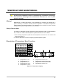
TEMPERATURE MONITORING .................................................................................................................67
General................................................................................................................................................67
Setup Connections ..............................................................................................................................67
Description of Temperature Menu Functions.......................................................................................67
IBP MONITORING ......................................................................................................................................69
General................................................................................................................................................69
Installing an IBP module......................................................................................................................69
Setup Connections ..............................................................................................................................70
Description of IBP Menu Functions .....................................................................................................70
Description of IBP Waveform Menu Functions....................................................................................72
CAPNOGRAPHY MONITORING................................................................................................................75
General................................................................................................................................................75
Setup Connections ..............................................................................................................................75
Warming Up.........................................................................................................................................76
Sample Line Checks ...........................................................................................................................76
Description of CO2 Menu Functions ....................................................................................................77
Description of Capno Waveform Menu Functions...............................................................................78
TRENDS......................................................................................................................................................81
General................................................................................................................................................81
Tabular Trend Data ..............................................................................................................................81
Graphical Trend Data ..........................................................................................................................83
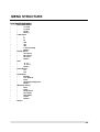
MENU STRUCTURE...................................................................................................................................85
PRINTING ...................................................................................................................................................99
General................................................................................................................................................99
Print Out Configuration......................................................................................................................100
EXTERNAL INTERFACE..........................................................................................................................103
General..............................................................................................................................................103
Cable Connections ............................................................................................................................103
Nurse Call Interface...........................................................................................................................104
MAINTENANCE ........................................................................................................................................105
Recycling and Disposal .....................................................................................................................105
Returning the Monitor and System Components ..............................................................................105
Service...............................................................................................................................................105
Periodic Safety Checks .....................................................................................................................105
Cleaning ............................................................................................................................................106
Battery Maintenance .........................................................................................................................106
Loading Recorder Paper ...................................................................................................................107
TROUBLESHOOTING..............................................................................................................................109
General..............................................................................................................................................109
Corrective Action ...............................................................................................................................109
EMI (Electromagnetic Interference)................................................................................................... 115
Obtaining Technical Assistance ......................................................................................................... 115
FACTORY DEFAULTS.............................................................................................................................. 117
General.............................................................................................................................................. 117
Parameter Ranges and Default Settings........................................................................................... 117
SPECIFICATION .......................................................................................................................................121
Display...............................................................................................................................................121
Controls .............................................................................................................................................121
Alarms ...............................................................................................................................................121
Physical Characteristics and Recorder .............................................................................................121
ii
Electrical ............................................................................................................................................122
Environmental Conditions .................................................................................................................122
Measurement Parameters.................................................................................................................123
Trends................................................................................................................................................126
Compliance........................................................................................................................................127
Manufacturer’s Declaration ...............................................................................................................129
Figures
Figure 1. Front Panel Components ........................................................................................................................................................ 7
Figure 2. Rear Panel Components......................................................................................................................................................... 9
Figure 3. Left Panel Components ........................................................................................................................................................ 10
Figure 4. Right Panel Components .......................................................................................................................................................11
Figure 5. Displays ................................................................................................................................................................................ 13
Figure 6. AC Power connection ........................................................................................................................................................... 21
Figure 7. Battery Placement ................................................................................................................................................................ 23
Figure 8. Initial Screen ......................................................................................................................................................................... 26
Figure 9. Typical Screen during monitoring ......................................................................................................................................... 26
Figure 10. Date/Time Menu ................................................................................................................................................................. 27
Figure 11. Setup Menu......................................................................................................................................................................... 28
Figure 12. Basic configuration display ................................................................................................................................................. 29
Figure 13. CO2 option display .............................................................................................................................................................. 30
Figure 14. IBP option display ............................................................................................................................................................... 30
Figure 15. IBP and CO2 option display................................................................................................................................................. 30
Figure 16. Alarm Limits Menu .............................................................................................................................................................. 39
Figure 17. Alarm Limits Setting ............................................................................................................................................................ 40
Figure 18. Auto Alarm setting menu..................................................................................................................................................... 42
Figure 19.Audible Alarm Silence Display ............................................................................................................................................. 43
Figure 20. Audible Alarm Suspend Display.......................................................................................................................................... 44
Figure 21. Standard 3 Electrode Placement ........................................................................................................................................ 46
Figure 22. 5 Electrode Placement........................................................................................................................................................ 46
Figure 23. HR/PR display..................................................................................................................................................................... 48
Figure 24. HR/PR Menu....................................................................................................................................................................... 48
Figure 25. ECG Waveform display....................................................................................................................................................... 49
Figure 26. ECG Waveform Menu......................................................................................................................................................... 49
Figure 27. NIBP display ....................................................................................................................................................................... 55
Figure 28. NIBP menu.......................................................................................................................................................................... 55
Figure 29. SpO2 Display....................................................................................................................................................................... 60
Figure 30. SpO2 Menu ......................................................................................................................................................................... 60
Figure 31. Pleth Waveform Display...................................................................................................................................................... 61
Figure 32. Pleth Waveform Menu ........................................................................................................................................................ 61
Figure 33. Respiration Display ............................................................................................................................................................. 64
Figure 34. Respiration Menu................................................................................................................................................................ 64
Figure 35. Respiration Waveform Display............................................................................................................................................ 66
Figure 36. Respiration Waveform Menu .............................................................................................................................................. 66
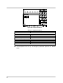
Figure 37. Temperature Display ........................................................................................................................................................... 67
Figure 38. Temperature Menu.............................................................................................................................................................. 68
Figure 39. IBP Module Installation ....................................................................................................................................................... 69
Figure 40. IBP Display ......................................................................................................................................................................... 70
Figure 41. IBP Menu ............................................................................................................................................................................ 71
Figure 42. IBP Waveform Display ........................................................................................................................................................ 72
Figure 43. IBP Waveform Menu ........................................................................................................................................................... 73
Figure 44. Connecting the sample line ................................................................................................................................................ 76
Figure 45. CO2 Display ........................................................................................................................................................................ 77
Figure 46. CO2 Menu ........................................................................................................................................................................... 77
Figure 47. Capno Waveform Display ................................................................................................................................................... 78
Figure 48. Capno Waveform Menu ...................................................................................................................................................... 78
Figure 49. Tabular Trend Screen.......................................................................................................................................................... 81
Figure 50. Tabular Trend Menu ............................................................................................................................................................ 82
Figure 51. Graphical Trend Screen ...................................................................................................................................................... 83
Figure 52. Graphical Trend Menu ........................................................................................................................................................ 83
Figure 53. 20 Sec Printing ................................................................................................................................................................. 100
iii
Figure 54. Continuous Printing .......................................................................................................................................................... 100
Figure 55. Tabular Trend Printing....................................................................................................................................................... 100
Figure 56. Graphical Trend Printing ................................................................................................................................................... 101
Figure 57. Setting Information Printing .............................................................................................................................................. 101
Figure 58. Data Port Pin Layout......................................................................................................................................................... 103
Figure 59. Recorder Paper Replacement .......................................................................................................................................... 107
Tables
Table 1. BP-S510 Controls..................................................................................................................................................................... 8
Table 2. Panel and Label Symbols....................................................................................................................................................... 12
Table 3. Display Symbols..................................................................................................................................................................... 14
Table 4. Display Colors ........................................................................................................................................................................ 15
Table 5. Standard Accessories............................................................................................................................................................. 18
Table 6. Optional Accessories.............................................................................................................................................................. 20
Table 7. Front panel Indications for power source ............................................................................................................................... 23
Table 8. The Monitor Battery Status Icon ............................................................................................................................................. 24
Table 9. Front Panel Indications for Battery Status .............................................................................................................................. 24
Table 10. Date/Time Menu ................................................................................................................................................................... 27
Table 11. Setup Menu .......................................................................................................................................................................... 28
Table 12. High Priority Alarm................................................................................................................................................................ 34
Table 13. Medium Priority Alarm .......................................................................................................................................................... 36
Table 14. Low Priority Alarm ................................................................................................................................................................ 36
Table 15. Informative Messages .......................................................................................................................................................... 37
Table 16. Visual Alarm Characteristics................................................................................................................................................. 38
Table 17. Audible Alarm Characteristics .............................................................................................................................................. 38
Table 18. Alarm Limits Menu................................................................................................................................................................ 40
Table 19. Alarm Limits Ranges ............................................................................................................................................................ 41
Table 20. ECG Lead Colors ................................................................................................................................................................. 47
Table 21. ECG Lead Pairs ................................................................................................................................................................... 47
Table 22. HR/PR Menu ........................................................................................................................................................................ 48
Table 23. ECG Waveform Menu .......................................................................................................................................................... 50
Table 24. Cuff Size ............................................................................................................................................................................... 53
Table 25. NIBP Menu ........................................................................................................................................................................... 56
Table 26. SpO2 Sensors ...................................................................................................................................................................... 59
Table 27. SpO2 Menu .......................................................................................................................................................................... 60
Table 28. Pleth Waveform Menu .......................................................................................................................................................... 61
Table 29. Respiration Menu ................................................................................................................................................................. 64
Table 30. Respiration Waveform Menu ................................................................................................................................................ 66
Table 31. Temperature Menu ............................................................................................................................................................... 68
Table 32. IBP 1 Menu........................................................................................................................................................................... 71
Table 33. IBP 2 Menu........................................................................................................................................................................... 71
Table 34. (P1 Label) Waveform Menu ................................................................................................................................................. 73
Table 35. (P2 Label) Waveform Menu ................................................................................................................................................. 73
Table 36. CO2 Menu............................................................................................................................................................................. 77
Table 37. Capno Waveform Menu ....................................................................................................................................................... 78
Table 38. Tabular Trend Menu.............................................................................................................................................................. 82
Table 39. Graphical Trend Menu .......................................................................................................................................................... 84
Table 40. RS-232 Serial Interface Connections ................................................................................................................................. 103
Table 41. Parameter Ranges and Factory Defaults ............................................................................................................................117
Table 42. Electromagnetic Emissions (IEC60601-1-2) ...................................................................................................................... 129
Table 43. Electromagnetic Immunity (IEC60601-1-2) ........................................................................................................................ 129
Table 44. Electromagnetic Immunity (IEC60601-1-2) ........................................................................................................................ 130
Table 45. Recommended Separation Distances ................................................................................................................................ 131
Table 46. Cables (IEC60601-1-2) ...................................................................................................................................................... 131
iv
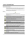
SAFETY INFORMATION
General Safety Information
This section contains important safety information related to general use of the BP-S510
multi-parameter patient monitor. Other important safety information appears throughout
the manual. The BP-S510 will be referred to as the monitor throughout this manual.
Important! Before use, carefully read this manual, accessory directions for use, all
precautionary information and specifications.
Warning
Warnings are identified by the WARNING symbol shown above.
Warnings alert you to potential serious outcomes (death, injury, or adverse events)
to the patient or user.
WARNING: Do not take into or use the monitor in locations where highly
combustible anesthetics or flammable gases are used or in high-pressure oxygen
rooms or inside oxygen tents, as this may cause a flammable explosion.
WARNING: When using the monitor with a commercial electric power source, use
the monitor with an electric power wall socket with a grounding wire for medical
use. Not doing so could cause electric shock.
WARNING: Do not connect grounding wire to gas pipes. This could cause fire.
WARNING: Only doctors and officially certified personnel should use this monitor.
Do not allow patients to touch this monitor. Allowing patients to touch this monitor
could cause accidents.
WARNING: This monitor cannot be used when MRI is in progress. If MRI is in use,
keep patient attachments away from patients to prevent accidents.
WARNING: The monitor conforms to the requirements of the EMC standard
(IEC60601-1-2), and may therefore be used simultaneously with pacemakers and
other electrical simulators. It should, however, be noted that the BP-S510 may be
affected by electrical scalpels and microwave therapeutic apparatus. Please check
operation of the monitor during and after use of such equipment.
WARNING: Do not take mobile phones or transceivers into a room where this
monitor is installed, as such devices may cause accidents.
WARNING: In order to avoid accidents, do not use any unauthorized accessories
or options.
WARNING: Thoroughly read the instruction manuals supplied with accessories
and options to ensure correct use. This instruction manual does not carry the
caution selections for such equipment.
WARNING: Do not open cover or disassemble this monitor. Doing so could cause
electric shock or fire. It is prohibited by law to modify the monitor without
authorization.
WARNING: Do not use power source other than the specified voltage, (100240V~50/60Hz) as this may cause fire or electric shock.
1
WARNING: Pre-use inspection and preventive maintenance must be performed for
safe use.
WARNING: The monitor may be used with electrical surgical equipment.
Follow the instruction manuals for medical instruments – notably electrosurgical
and diathermy instruments – when used, as their high – frequency energy units
may cause burns to patients via attachments.
WARNING: This monitor is protected against the discharge of a defibrillator. But
do not touch the monitor when a defibrillator is being discharged (electrified), as
doing so may cause electric shock.
WARNING: The following cautions apply when connecting he monitor with other
equipment.
1. Ensure that the connected equipment is in accordance with the IEC60601-1 or
IEC safety standards, so that the system complies with IEC60601-1.
2. Employ additional protective measures (e.g. additional protective earthing) as
necessary.
WARNING: Do not connect devices that do not meet medical safety standards
(such as commercial PCs), as they may cause electric shock. This monitor meets
the restricted level of leakage current required for medical devices. Therefore, this
monitor cannot be connected to a device that would give a combined total of
leakage current beyond the restricted level.
WARNING: Do not place anything on top of this monitor. If something is spilled
over the monitor or gets into it, such spillage may cause fire or electric shock. If
fluid spills on the monitor accidentally, disconnect power cord, wipe dry
immediately, and have the monitor serviced to make sure that no hazard exists.
WARNING: Do not place heavy objects on the power cord, as doing so may cause
fire or electric shock.
WARNING: Before conducting maintenance work, turn the power OFF and unplug
the power cord from the wall socket to prevent electric shock.
WARNING: When the following occur, turn the power OFF immediately and unplug
the power cord from the wall socket. Continued use in such situations may cause
fire or electric shock.
z
There is smoke or a strange odor leaking out of the device.
z
The devices has been dropped or impacted by an object.
z
Liquid or foreign matter gets inside the device.
z
Device failure has occurred.
Also, when any of the above occurs, promptly do the following:
1. Check to see that the power cord has been unplugged from the wall socket.
2. Place an “Out of Order” sign on the device and do not use it.
WARNING: Do not connect more than one patient to the monitor. Do not connect
more than one monitor to a patient.
WARNING: The patient monitor is a prescription device and is to be operated by
qualified personnel only.
2
Cautions
Cautions are identified by the CAUTION symbol shown above.
Caution statements identify conditions or practices that could result in damage to
the equipment or other property.
CAUTION: The monitor may not operate properly if it is operated or stored at
conditions outside the ranges stated in this manual, or subjected to excessive
shock or dropping.
CAUTION: When connecting the patient monitor to any instrument, verify proper
operation before clinical use. Both the monitor and the instrument connected to it
must be connected to a grounded outlet.
CAUTION: Accessory equipment connected to the monitor’s data interface must be
certified according to IEC60950 for data-processing equipment or IEC60601-1 for
electromedical equipment. All combinations of equipment must be in compliance
with IEC60601-1-1 system requirements. Anyone who connects additional
equipment to the signal input or signal output port configures a medical system
and is therefore responsible that the system complies with the requirements of IEC
60601-1-1 and the electromagnetic compatibility system standard IEC60601-1-2. If in
doubt, consult Colin Medical Technology Technical Support Representative.
CAUTION: Risk of explosion if battery is replaced by an incorrect type.
CAUTION: Where the integrity of the external protective conductor in the
installation or its arrangement is in doubt, equipment shall be operated from its
internal electrical power source.
3
This page is intentionally left blank.
4
INTRODUCTION
WARNING: Patient conditions may result in erroneous readings. If the
measurements are suspect, verify the reading using another clinically accepted
measurement method.
Intended Use for the BP-S510
The BP-S510 is intended to be used to monitor electrocardiography (ECG), heart rate
(HR), noninvasive blood pressure (NIBP) - systolic, diastolic and mean arterial pressures,
functional arterial oxygen saturation (SpO2), pulse rate (PR), respiration (RR),
temperature (Temp), invasive blood pressure (IBP) and capnography (EtCO2 and InCO2)
for adult and neonatal patients in all areas of a hospital and hospital-type facilities. Monitor
users should be skilled at the level of a technician, doctor, nurse or medical specialist.
Note: Hospital use typically includes such areas as general care floors, operating rooms,
special procedure areas, intensive and critical care area, within the hospital.
Hospital-type facilities include physician office-based facilities, sleep labs, skilled
nursing facilities, surgical centers, and sub acute care centers.
About This Manual
This manual explains how to set up and use the BP-S510 patient monitor.
Read the entire manual including the Safety Information section, before you
operate the monitor.
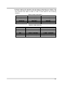
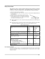
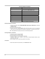
Identifying the BP-S510 monitor Configurations
The following table identities BP-S510 monitor configurations and how they are indicated.
The model-option number and serial number are located on the back of the monitor.
All information in this manual, including the illustrations, is based on a monitor configured
with the Capnography (EtCO2 and InCO2), IBP and recorder. If the relevant functions do
not exist, please verify your unit configuration.
Configuration
BP-S510
REF No.
112580
BP-S510P
BP-S510C
BP-S510PC
S510-IBP
112581
112582
112583
131324
Description
Standard
(ECG, NIBP, SpO2, 2-channel Temperature, Respiration)
Standard + Recorder
Standard + Capnography
Standard + Capnography + Recorder
2-channel IBP module
5
Features for the BP-S510
Physical/Mechanical
The BP-S510 is a multi-parameter patient monitor which can be battery-operated when
AC power source is not available.
Electrical
The BP-S510 is powered by an internal battery pack that typically provides one hour of
monitoring from fully charged new batteries. The batteries are continuously recharged
when the monitor is connected to AC power source. Refer to the Battery Operation
section for details.
Display
The monitoring screen is a color LCD that shows all graphic and numeric patient
information as well as status conditions and warning messages.
Jog dial
The jog dial provides user interaction with the display and the monitor functions. Rotating
and pressing the jog dial allows the user to navigate and make changes to the display
elements and monitor functions. Refer to the Using the Monitor section for details.
Auxiliary Outputs
The monitor provides RS-232, LAN and USB ports.
6
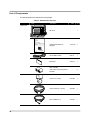
DESCRIPTION OF THE MONITOR
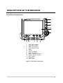
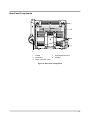
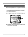
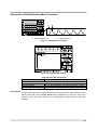
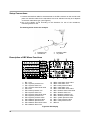
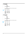
Front Panel Components
1
2
3
4
5
6
7
8
9
10
11
12
13
Visual alarm indicator
Alarm silence button
NIBP interval button
NIBP start/stop button
LCD
Jog dial
Power on indicator
Power on/off button
Battery charging indicator 1
Battery charging indicator 2
Record button
Trend button
Home button
Figure 1. Front Panel Components
7
Table 1. BP-S510 Controls
Symbols
Description
Power on/off button
turns the monitor on or off.
Record button
prints measured data if an optional recorder is installed.
Alarm silence button
silences the audible alarm temporarily.
suspends the audible alarm by pressing over 2 seconds.
NIBP interval button
allow you to set the NIBP auto measurement interval.
NIBP start/stop button
toggles between starting and stopping NIBP measurements.
Home button
exits a menu displayed on the screen and goes to the main
screen.
Trend button
allows you to set the trend display.
Jog dial
provides user interaction with the monitor to control the
functions.
8
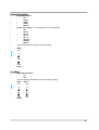
Rear Panel Components
1
2
3
Handle
Ventilators
VESA connector holes
4
5
Equipotential terminal
Speaker
Figure 2. Rear Panel Components
9
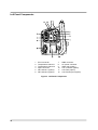
Left Panel Components
1
2
3
4
5
6
ECG connector
Temperature channel 1
Temperature channel 2
SpO2 connector
IBP channel 1 (option)
IBP channel 2 (option)
7
8
9
10
11
12
NIBP connector
AC power connector
Water trap (option)
CO2 connector (option)
CO2 Filter (option)
CO2 Exhaust port (option)
Figure 3. Left Panel Components
10
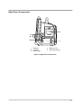
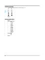
Right Panel Components
1
2
3
USB port
LAN port
RS-232 port
4
5
Battery cover
Recorder (option)
Figure 4. Right Panel Components
11
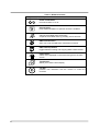
Table 2. Panel and Label Symbols
Symbols
12
Description
Symbols
Description
Power on indicator
EU representative
Battery charging indicator 1
Dust and water resistance
Battery charging indicator 2
Attention, consult
accompanying documents
Visual alarm indicator
CE mark
Type CF- Defibrillator proof
Crossed-out wheeled bin
ECG connector
Manufacturer
Temperature connector
Date of manufacture
SpO2 connector
Reference number
NIBP connector
Serial number
IBP connector
Environmental shipping/storage
altitude limitations
CO2 connector
Environmental shipping/storage
humidity limitations
CO2 Filter
Environmental shipping/storage
temperature limitations
USB port
Fragile-handle with care
LAN port
This way up
RS-232 interface port
Keep dry
Battery placement & rating
Attention: consult
accompanying documents
Equipotential terminal
Handle with care
AC power input rating
Stack up to 3 boxes
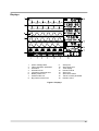
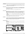
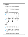
Displays
1
2
3
4
5
6
7
8
Alarm message area
Title of waveform parameter
Waveform
Waveform area
Informative message area
Battery status icon
Patient mode icon
Big number screen icon
9
10
11
12
13
14
15
16
Setup icon
Alarm limits icon
Time display
Numerical area
Alarm icon
Alarm limit values
Title of numeric parameter
Numeric value
Figure 5. Displays
13
Table 3. Display Symbols
Symbols
Description
14
Description
ECG waveform icon
NIBP auto mode Interval
ECG lead pair
NIBP elapsed time
ECG size scale
SpO2 icon and unit
ECG size bar
Pulse amplitude indicator
P1 Label
Respiration rate icon & unit
P2 Label
Respiration source icon: Im
P1 or P2 Label:
Arterial Blood Pressure
P2 Label:
Central Venous Pressure
P2 Label:
Pulmonary Artery Pressure
P2 Label:
Left Atrial Pressure
InCO2 icon: Inspired carbon
dioxide concentration
EtCO2 icon: End-tidal carbon
dioxide concentration
Plethysmograph icon
Temperature channel 1 icon
Capnograph icon
Temperature channel 2 icon
Impedance respiration
waveform icon
Delta T icon |T1-T2|
HR/PR icon & unit
Temperature unit: Celsius
HR source icon: ECG
Temperature unit: Fahrenheit
PR source icon: IBP1
Battery status icon
PR source icon: IBP1
Big number screen icon
PR source icon: SpO2
Setup icon
PR source icon: NIBP
Alarm limits icon
NIBP icon
Patient mode: Adult
NIBP, IBP or EtCO2 unit:
mmHg
NIBP, IBP or EtCO2 unit:
kPa
%
Symbols
Respiration source icon: Aw
Lung icon
Patient mode: Neonatal
Time display
EtCO2 unit: %
Alarm limits value
Systolic pressure icon
Alarm icon
MAP or Mean pressure icon
Audible Alarm silence icon
Diastolic pressure icon
Audible Alarm suspend icon
Symbols
Description
Symbols
Description
NIBP graphical trend icon
HR/PR graphical trend icon
T2 graphical trend icon
SpO2 graphical trend icon
T1 graphical trend icon
IBP graphical trend icon
EtCO2 graphical trend icon
Respiration graphical trend icon
Table 4. Display Colors
Function
ECG and HR/PR
Plethysmograph and SpO2
NIBP
Respiration
Temperature
Capnograph, InCO2 and EtCO2
IBP1 (P1 Label)
IBP2 (P2 Label)
General background
Informative message
Low priority alarm message
Medium priority alarm message
High priority alarm message
Battery status icon (normal)
Battery status icon (low battery)
Color
Green
Cyan
Yellow
White
Pink
Orange
Purple
Blue
Black
Black background, White font
White background, Black font,
Yellow background, Black font,
Red background, Black font,
Green
Yellow or Red (refer to Table 8)
15
This page is intentionally left blank.
16
SETTING UP THE MONITOR
WARNING: To ensure accurate performance and prevent device failure, do not
expose the monitor to extreme moisture, including direct exposure to rain. Such
exposure may cause inaccurate performance or device failure. Refer to
Specification section.
WARNING: The monitor should not be used adjacent to or stacked with other
equipment. If adjacent or stacked use is necessary, the monitor should be
observed to verify normal operation in the configuration it is to be used.
WARNING: Make sure that the monitor speaker is not obstructed. Failure to do so
could result in an inaudible alarm tone.
CAUTION: Recharging the battery is strongly recommended when the battery has
not been recharged for 2 or more months.
CAUTION: Follow local government ordinances and recycling instructions
regarding disposal or recycling of device components, including batteries.
Unpacking and Inspection
The monitor is shipped in one carton. Examine the carton carefully for evidence of
damage. Contact Colin Medical Technology Technical Support Representative
immediately if any damage is discovered. Refer to the Maintenance section for
instructions on returning damaged items.
Note: Refer to Performance Verification section in the service manual for the detailed
information.
17
List of Components
The following items are standard in the package.
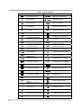
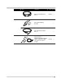
Table 5. Standard Accessories
Figure
Description
REF
Q’ty
Main Unit
BP-S510
-
1
OPERATION MANUAL
(English)
1731064
1
AC POWER CORD
046111
1
BATTERY
040074
1
-
2
CUFF No.3 (12cm)
A013ZZ
1
CUFF HOSE No.1 (3.5m)
A015ZZ
1
ECG CABLE No.8
AY1005
1
ROLL PAPER
*Only when Recorder option is
installed.
For NIBP
For ECG
18
Figure
Description
REF
Q’ty
For ECG
ECG 3-LEAD WIRES No.5
(G,R,Y)
AG1002
1
SpO2 DURA SENSOR
DS-100A
-
1
SpO2 EXTENSION CABLE
DOC-10
-
1
SAMPLING SET
(AIRWAY ADAPTER, NAFION
TUBE & SAMPLING TUBE)
*Only when CO2 option is
installed.
C010ZZ
1
For SpO2
For CO2
19
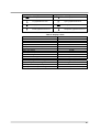
Optional items listed below can be ordered. Contact your local sales supplier for the
detailed information.
Table 6. Optional Accessories
REF
NIBP
ECG
SpO2
CO2
IBP
TEMP
20
Unit
Min.Qty
A012ZZ
CUFF No.2 (9cm)
pce
-
A014ZZ
CUFF No.4(14cm)
pce
-
AL021Z
CUFF No.10(2.5cm)
pce
10
AL022Z
CUFF No.11(3cm)
pce
10
AL023Z
CUFF No.12(4cm)
pce
10
AL024Z
CUFF No.13(5cm)
pce
10
A016ZZ
CUFF HOSE No.2(1.5m)
pce
-
AL012Z
CUFF HOSE No.3(3.5m)
pce
-
AG006Z
ECG ELECTRODES 25pcs/bag
bag
1
AG1003
ECG 5-LEAD WORES No.6(G,R,Y,W,B)
pce
-
-
ADULT FINGER OXISENSOR MAX-A
-
-
-
CHILD FINGER OXISENSOR MAX-P
-
-
-
NEONTAL OXISENSOR MAX-N
-
-
-
INFANT OXISENSOR MAX-I
-
-
-
ADULT NASAL OXISENSOR MAX-R
-
-
-
MAX-FAST
-
-
C005ZZ
WATER TRAP
-
-
C003ZZ
NAFION TUBE
pce
10
C004ZZ
SAMPLING TUBE
pce
10
C002ZZ
AIR WAY ADAPTER
pce
10
AS012Z
IBP DISPOSABLE TRANSDUCER DT-12
pce
10
AS011Z
IBP DISPOSABLE TRANSDUCER DT-4812
pce
10
046432
IBP INTERFACE CABLE TC-COL-2
pce
1
AS004Z
pce
1
pce
1
1731064A
BT Sensor Model 401J/Rectum, Gullet
(produced by YSI)
BT Sensor Model 402J/Rectum,
Gullet/Small(produced by YSI)
OPERATION MANUAL (English)
pce
1
1731065A
OPERATION MANUAL (German)
pce
1
AS005Z
Others
Description
1731066A
OPERATION MANUAL (French)
pce
1
1731093A
OPERATION MANUAL (Portugese)
pce
1
1731068A
OPERATION MANUAL (Spanish)
pce
1
1731071A
SERVICE MANUAL (English)
pce
1
040074
BATTERY (BP-S510)
-
-
048151
ROLL PAPER BP-S510
-
-
A023ZZ
GROUDING WIRE TYPE1
pce
1
A024ZZ
GROUDING WIRE TYPE2
pce
1
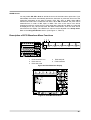
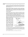
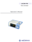
Power Cable Connections
WARNING: Do not connect to an electrical outlet controlled by a wall switch
because the device may be accidentally turned off.
CAUTION: If in doubt the integrity of the AC power source, the monitor must be
operated from its internal battery.
AC Power
Make sure that the AC outlet is properly grounded and supplies the specified voltage and
frequency (100-240V~ 50-60 Hz).
Figure 6. AC Power connection
1. Connect the female connector end of the AC power cord to mains connector on the
monitor’s left panel.
2. Plug the male connector end of the AC power cord into a properly grounded mains
outlet.
3. If necessary, connect grounding wire. Connect the grounding wire connector to the
equipotential terminal on the rear panel. Now attach the clip end of the grounding wire
to the medical equipment grounding terminal on the wall.
4. Verify that Battery charging indicator on the monitor’s front panel is lit.
Note: Even if the monitor is not turned on, the Battery charging indicator is lit when the
AC power cord is connected into a mains outlet.
Note: If Battery charging indicator is not lit, check:
z
z
z
z
the power cord
the AC power inlet
the power/ mains outlet
No Battery
If the Battery charging indicator still is not lit although any problem is not found,
contact qualified service personnel or your local supplier for assistance.
21
Measurement Cable Connections
WARNING: For best product performance and measurement accuracy, use only
accessories supplied or recommended by Colin Medical Technology. Use
accessories according to the manufacturer’s directions for use and your facility’s
standards. Use only accessories that have passed the recommended
biocompatibility testing in compliance with ISO10993-1.
Note: Both frequent checks by the operator on daily basis and more comprehensive
technical checks less frequently are covered by this requirement in order to detect
mechanical damage and damage to cables, etc.
ECG Cables and Leads
1. Connect an ECG cable to the “ECG” connector making sure that the connector arrow is
pointing panel.
2. Attach the ECG lead wire to the end of the cable. (see Figure 3)
NIBP Hoses and Cuffs
1. Select an appropriate size cuff for the patient. (Refer to the NIBP Monitoring section.)
2. Connect the hose to the “CUFF” connector making sure to tighten the connector in the
clockwise direction.
3. Attach the cuff to the end of the hose. (see Figure 3)
SpO2 Cables and Sensors
1. Select an appropriate sensor for the patient and desired application. (Refer to the SpO2
Monitoring section.)
2. Connect the extension cable DOC-10 to the “SpO2” connector on the monitor’s left
panel.
3. Attach the sensor to the end of the cable. (see Figure 3)
Temperature Probes
1. Select the appropriate probe(s) for the desired application.(YSI 400 Series)
2. Connect the temperature probes to the “T1” and/or “T2” connector on the monitor’s left
panel. (see Figure 3)
IBP Transducers (option)
1. Connect the interface cable(s) for the transducer(s) to the IBP connector on the
monitor’s left panel. An interface cable for the transducer has to be selected correctly
as it depends on the transducer type. (see Figure 3)
2. Set up the patient circuit according to the directions for use of the transducer,
monitoring kit and IV set.
CO2 Sampling set (option)
1. Connect a sampling tube to the “Water Trap” port on the monitor’s left panel. (see
Figure 3)
2. Connect the nafion tube to the sampling tube.
3. Connect the nafion tube to the airway adaptor.
Note: If lead wires/cables, cuffs/hose cables, sensors and/or probes are not connected
firmly, the monitor could lose signals from the patient.
22
BATTERY OPERATION
CAUTION: Recharging battery is strongly recommended when it has not been fully
recharged for 2 or more months.
CAUTION: When the voltage of the battery is very low, it is a possibility of not
operating.
Note: It is recommended that the monitor remain connected to AC power source when not
in use. This will ensure a fully charged battery whenever it is needed.
Note: As the battery is used and recharged over a period of time, the amount of time
between the onset of the low battery alarm and the instrument shut-off may become
shorter.
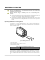
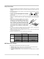
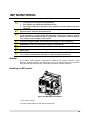
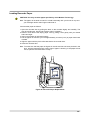
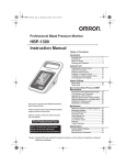
Operating the Monitor on Battery Power
The monitor has an internal battery that can be used to power the monitor when AC
power source is not available. The battery status icon appears on the screen when the
monitor is on battery power.
Figure 7. Battery Placement
1. Turn off the monitor.
2. Open the battery cover by pressing the latch.
3. Insert the battery carefully.
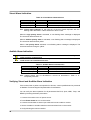
Table 7. Front panel Indications for power source
Power Connections
AC source
Battery
Front panel Indications
Battery charging indicator is lit.
Battery status icon appears on the screen.
The monitor cannot operate with a fully discharged battery. Before turning on the monitor
with the battery that has been completely discharged, first plug the monitor into an AC
outlet to charge the battery for minimum 3 minutes. The monitor may then be powered
on.
23
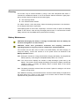
A new, fully charged battery will provide 1 hour monitoring operation under the following
conditions:
z
z
z
z
z
z
Operation of ECG, Respiration, SpO2, Temperature, CO2 and IBP
NIBP automatic measurement per 5 minutes
No audible alarm condition
No external communication operating
No printing
Ambient temperature at 25°C
Battery Status Indication
When operating on batteries, the battery status icon in the lower part of the display
indicates the battery charge condition. See Table 8.
Table 8. The Monitor Battery Status Icon
Battery Status Icons
Battery Status Icon Color
Green (constant)
Yellow (constant) ≤ 15 minutes
Red (flashing) ≤ 5 minutes
A low priority alarm occurs when the remaining battery power is only enough for 15
minutes of operation. The alarm message ‘Low Battery’ appears on the screen and the
visual alarm indicator is lit with yellow.
This alarm cannot be silenced while running on battery power. Connecting the monitor to
AC power will silence the alarm.
A high priority alarm occurs for about 5 minutes before the monitor shuts off. The alarm
message ‘Critically Low-Battery Condition’ will appears and the visual alarm indicator
will flash with red. After that, the monitor will automatically shut down. Connect the
monitor to an AC power source to avoid any loss of trend data or settings.
Charging a Low Battery
1. Connect the monitor to AC power source to charge a low or depleted battery.
(see the Setting up the Monitor section)
2. Verify that Battery charging indicator is lit with orange.
Table 9. Front Panel Indications for Battery Status
Battery status
Full charged
Charging
Not installed
Battery charging indicator
Green
Orange
Off
Note: Even if the monitor is turned off, Battery charging indicator is lit while the battery
is recharged.
Note: A full charge of a depleted battery takes over 12 hours per battery.
24
USING THE MONITOR
WARNING: If the Power On Self-Test is not completed successfully, do not try to
use the monitor.
WARNING: Each time the monitor is used, check alarm limits to make sure that
they are appropriate for the patient being monitored.
WARNING: Keep patients under close surveillance when monitoring. It is
possible, although unlikely, that radiated electromagnetic signals from sources
external to the patient and the monitor can cause inaccurate measurement
readings. Do not rely entirely on the monitor readings for patient assessment.
Turning on the Monitor
Before using the monitor, confirm that the monitor is working properly and is safe to use
as described below.
CAUTION: When power is applied, the monitor automatically starts the Power-On
Self-Test (POST), which tests the monitor circuitry and functions. During POST,
confirm that the monitor screen turns on. If the monitor screen does not function
properly, do not use the monitor. Instead, contact qualified service personnel or
your local supplier.
Note: The post test tone sounds when the monitor completes the Power-On Self-Test
(POST). This functions as an audible confirmation that the speaker is performing
properly. If the speaker does not function, the alarm warning sounds cannot be
heard.
Note: If there is any problem on the speaker during the operation, the buzzer generates
the sound automatically to alert the user to notice the speaker failure. If unusable
sound like buzzer can be heard, do not use the monitor. Instead, please contact
qualified service personnel or your local supplier.
1. Turn on the monitor by pressing Power on/off button. Confirm that the Power on
indicator on the monitor’s front panel is lit.
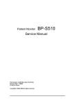
2. After the checksum for flash memory is completed, the monitor performs POST. The
initial screen appears during POST. The initial screen displays the company logo, the
version of system and the current time.
3. If there is no error, all indicators are lit for at least 2 seconds and the post pass tone
sounds during POST. Confirm that the post pass tone sounds and all indicators are lit
during POST.
25
Figure 8. Initial Screen
Note: The system version shown above is only an example.
4. After power-up diagnostics are successfully completed, the monitor is ready for
operation.
Note: If the monitor detects an internal problem during POST, the monitor will display an
error code and will not display the monitoring screen. If an error code is displayed
during POST, contact qualified service personnel or your local supplier for
assistance.
5. When the monitor detects valid signals, it displays real-time waveforms similar to Figure
9.
Figure 9. Typical Screen during monitoring
26
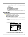
Setting Date and Time
You may set the date and time displayed on the screen and printed on the reports.
1. Rotate the jog dial to highlight Time display, and then press the jog dial to select
Date/Time menu.
2. Rotate the jog dial to display the desired number for year, month, day, hour or minute,
and then press the jog dial to select the desired number.
Note: The time format is 24 hours only. The date format can be set via Service menu.
Figure 10. Date/Time Menu
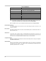
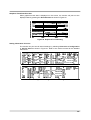
Table 10. Date/Time Menu
Level 1 Menu
DATE/TIME MENU
Date
Time
Level 2 Menu or Response
Year
Month
Day
Hour
Min
Return
27
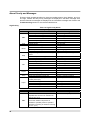
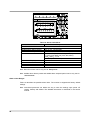
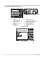
Setting Basic Setup Parameters
This procedure will allow you to set Patient Mode, Record Speed, Wave Record Time,
Wave Record Select, Record On Alarm, Auto List Record, Alarm Volume, HR/PR Tone
Volume, Key Beep Volume, Sleep Mode, Main Screen and Service menu.
Figure 11. Setup Menu
Table 11. Setup Menu
Level 1 Menu
SETUP MENU
Patient Mode
Record Speed*
Wave Record Time*
Wave Record Select*
Record On Alarm*
Auto List Record*
Alarm Volume
HR/PR Tone Volume
Key Beep Volume
Sleep Mode
Main Screen
Service Menu
Return
Level 2 Menu or Response
Adult, Neonatal
25.0mm/s, 50.0mm/s
20 sec, Continuous
ECG 1 + ECG 2
ECG 1 + PLETH
ECG 1 + RESP
ECG 1 + (P1 Label)
ECG 1 + (P2 Label)
ECG 1 + CAPNO
On, Off
On, Off
1, 2, 3, 4, 5, 6, 7, 8
Off, 1, 2, 3, 4, 5, 6, 7
Off, 1, 2, 3, 4, 5, 6, 7
Off, 10, 20, 30 minutes
4-ch Wave, 6-ch Wave, Big Number
(Pass code required)
Note: The menu options followed by an asterisk (*) are only displayed with an optional
recorder installed.
Note: If there is no activity for 20 seconds, the monitor will return to main screen.
28
Patient Mode
1. Rotate the jog dial to highlight Setup icon. Press the jog dial to display the setup menu.
2. Rotate the jog dial to highlight Patient Mode, and then press the jog dial to select an
appropriate mode: Adult or Neonatal.
Setting Record
If an optional recorder is installed, this menu will allow you to set Record Speed, Wave
Record Time, Wave Record Select, Record On Alarm and Auto List Record. Refer to
the Printing section for details.
Note: These menus are grayed out if no recorder installed in the monitor.
Setting Volume
Setting Volume allows you to adjust an audible alarm volume, Key beep volume and
HR/PR tone volume. Alarm volume can be set level 1 to 8 and Key beep volume and
HR/PR tone volume can be set level 1 to 7 or Off. (see Alarms and Limits section)
1. Rotate the jog dial to highlight Alarm volume, Key beep volume or HR/PR tone
volume.
2. Press the jog dial. Levels of Alarm volume, Key beep volume or HR/PR tone volume
will appear.
3. Rotate the jog dial to select a volume level. (see each volume level in the Table 11).
4. Press the jog dial to enter a desired volume into the monitor.
Sleep Mode
The monitor can be set to sleep mode for saving the power. The back light of the screen
is turned on continuously when Off is selected, When 10 min, 20 min or 30 min is
selected, the back light of the screen will be turned off automatically after the selected
time if there is not any alarm condition and control by the user.
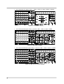
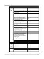
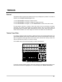
Setting Main Screen
You may select the number of the waveforms to be displayed; 4-ch wave, 6-ch wave or
Big number.
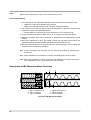
The following are the default screens of waveforms and big numbers as per each
configuration.
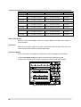
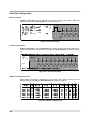
9
4-ch wave with basic configuration: ECG 1 + ECG 2 + SpO2 + RESP
Figure 12. Basic configuration display
29
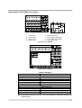
9
6-ch wave with CO2 option: ECG 1 + ECG 2 + ECG 3 + SpO2 + RESP + CAPNO
Figure 13. CO2 option display
9
6-ch wave with IBP option: ECG 1 + ECG 2 + IBP 1 + IBP 2 + SpO2 + RESP
Figure 14. IBP option display
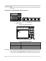
9
6-ch wave with IBP&CO2 option: ECG 1 + ECG 2 + IBP 1 + IBP 2 + SpO2 + CAPNO
Figure 15. IBP and CO2 option display
30
Note: The user can select a desired waveform in each waveform area.
1. Rotate the jog dial to highlight the waveform area to be changed.
2. Press the jog dial to display the waveform menu.
3. Select Waveform select by rotating and pressing the jog dial.
4. Select the desired waveform by rotating and pressing the jog dial.
Note: The monitor can display Big Number Screen by selecting Big number icon and
return to the main screen by selecting Big number icon again.
Note: The menus can be accessed in Big Number Screen without returning the main
screen.
Note: When an alarm condition occurs, the visual or audible alarm is activated in Big
Number Screen.
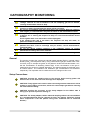
Service Menu
This menu includes Save Settings on Power off, Audible Alarm Silence Period, Audible
Alarm Suspend Period, Audible Alarm Type, AC Line Frequency, Unit Configuration,
Language Setting, Date Format, Jog Dial Speed, LAN Setting, System Setting, System
Test, NIBP Test and Demo Mode. Only authorized personnel is allowed to change the
Service Menu settings. A pass code is required for access. Refer to the service manual
for instructions.
31
This page is intentionally left blank.
32
ALARMS AND LIMITS
WARNING: Each time the monitor is used, check alarm limits to make sure that
they are appropriate for the patient being monitored.
General
When the monitor detects certain conditions that require user attention, the monitor enters
an alarm state. The monitor response is indicated by:
z
z
z
z
Visual alarm indication
Audible alarm indication
Physiological alarms including identification of out-of-limit vital signs
Technical alarms
Note: The audible and visual alarms on the monitor, used in conjunction with clinical
signs and symptoms, are the primary source for notifying medical personnel that
a patient alarm condition exists.
Changing Alarm Volume
You can select an alarm volume level 1 to 8. Refer to the Using the Monitor section (see
Figure 11, Table 11).
Taking an NIBP Measurement on Alarm
You can activate BP on Alarm via NIBP menu. Refer to the Using the Monitor section.
Initiating Print out on Alarm (Only when recorder option is installed)
You can activate Record on Alarm via Setup menu. Refer to the Printing section.
33
Alarm Priority and Messages
There are three possible priorities for visual and audible alarms: High, Medium, and Low.
The high, medium and low priority messages are displayed in the alarm message area,
and the informative messages are displayed in the informative message area. Refer to the
Troubleshooting section for the recommended actions.
High Priority
Table 12. High Priority Alarm
Parameter
NIBP
ECG
HR/PR
Resp
IBP
%SpO2
Temp
Capno
Parameter
NIBP
34
Physiological Alarm
Condition
Over the systolic BP upper limit
Under the systolic BP lower limit
Over the diastolic BP upper limit
Under the diastolic BP lower limit
Over the map BP upper limit
Under the map BP lower limit
Cardiac arrest
Over the heart rate upper limit
Under the heart rate lower limit
Over the pulse rate upper limit
Under the pulse rate lower limit
Respiration signal is not detected during
40sec.
Over the respiration rate upper limit
Under the respiration rate lower limit
Over the systolic upper limit
Under the systolic lower limit
Over the diastolic upper limit
Under the diastolic lower limit
Over the mean upper limit
Under the mean lower limit
Over the %SpO2 upper limit
Under the %SpO2 upper limit
Over the temperature upper limit
Under the temperature lower limit
Incapable of detecting respiration for
certain period (set).
Over the EtCO2 upper limit
Under the EtCO2 lower limit
Over the InCO2 upper limit
Under the InCO2 lower limit
Technical Alarm
Condition
Inflation doesn’t finish with specified time.
Specified time is 30 sec for adult and 20
sec for neo. (C11)
Measurement value can’t be calculated
even when inflated cuff pressure is
deflated to specified pressure. Specified
pressure is 10mmHg for adult and 5 mmHg
for neo. (C12)
Messages
NIBP: SYS upper limit violated.
NIBP: SYS lower limit violated.
NIBP: DIA upper limit violated.
NIBP: DIA lower limit violated.
NIBP: MAP upper limit violated.
NIBP: MAP lower limit violated.
ECG: Asystole.
HR: Upper limit violated.
HR: Lower limit violated.
PR({source}): Upper limit violated.
PR({source}): Lower limit violated.
Resp: Loss of respiration signal.
Resp: Upper limit violated.
Resp: Lower limit violated.
{label}: SYS upper limit violated.
{label}: SYS lower limit violated.
{label}: DIA upper limit violated.
{label}: DIA lower limit violated.
{label}: MEAN upper limit violated.
{label}: MEAN lower limit violated.
SpO2: Upper limit violated.
SpO2: Lower limit violated.
Temp{n}: Upper limit violated.
Temp{n}: Lower limit violated.
Capno: Apnea.
EtCO2: Upper limit violated.
EtCO2: Lower limit violated.
InCO2: Upper limit violated.
InCO2: Lower limit violated.
Messages
NIBP: Check cuff (C11)
NIBP: Check cuff / Patient (C12)
Parameter
NIBP
ECG
Resp
IBP
%SpO2
Temp
Capno
Technical Alarm
Condition
Deflation time is too long
Deflation speed is too low (C13)
Maximum inflating pressure is too low to
calculate patient BP value. (C14)
Abnormal pulse due to arrhythmia and too
much noise. (C15)
Collected pulse’s movement is abnormal.
(C16)
Measurement time is beyond specified
time. Specified time 160sec for adult and
80sec for neo. (C17)
Number of detected pulses is beyond
specified number. Specified number is 160
for both adult and neo. (C18)
Cuff pressure is beyond the pressure
specified for the patient safety. Specified
pressure is 300mmHg for adult and
150mmHg for neo. (C19)
The maximum value of collected pulse is
too low. (C20)
Cuff size is inadequate to patient. (C21)
NIBP module error
BPM pressure sensor fault.
Pump operated for ten seconds, however
pressure does not change.
Check the connection of the cuff hose.
NIBP module error
NIBP module error
NIBP module error
Fault detected in accordance with safety
monitoring to BPM IEC standards.
The pressure inside the cuff reaches the
standard pressure,
Standard pressure
Adult:
320mmHg
Neonatal: 157mmHg
NIBP module error
NIBP module error
NIBP module error
ECG module problem.
RESP module problem.
IBP signal is not detected.
IBP module problem.
SpO2 signal is not detected.
SpO2 module problem.
Temperature module problem.
Capno module have problem.
CO2 sensor error
Messages
NIBP: Cuff excessive artifact (C13)
NIBP: Cuff insufficient pressure
(C14)
NIBP: Cuff irregular pulses (C15)
NIBP: Cuff motion artifact (C16)
NIBP: Cuff time-out (C17)
NIBP: Cuff time-out, over 160 pulses
(C18)
NIBP: Cuff pressure failure (C19)
NIBP: Cuff weak pulse (C20)
NIBP: Check cuff, hose and mode
(C21)
NIBP: Internal error (E03)
NIBP: Internal error (E07)
NIBP: Internal error (E08)
NIBP: Internal error (E09)
NIBP: Internal error (ROM)
NIBP: Internal error (RAM)
NIBP: Internal error (COM)
ECG: Internal error.
Resp: Internal error.
{label}: Loss of pulse.
IBP: Internal error.
SpO2: Loss of pulse.
SpO2: Internal error.
TEMP{n}: Internal error.
Capno: Internal error.
Capno: Sensor error.
35
Parameter
System
Technical Alarm
Condition
Critically low battery condition. The device
will be automatically turned off within 5
minutes.
Real time clock is malfunction.
Watch dog timer is malfunction.
Data memory is broken.
Manufacturer use
Messages
System: Critically low-battery
condition.
System: Real time clock error.
System M: WDT error.
System M: RAM error.
System: Failure.
Medium Priority
Table 13. Medium Priority Alarm
Parameter
ECG
IBP
%SpO2
Temp
Capno
Technical Alarm Message
Condition
Patient lead of cable disconnected.
Transducer or interface cable is
disconnected.
Sensor or cable is disconnected.
Temperature probe is disconnected.
Occlusion alarm.
Water trap full alarm.
Messages
ECG : Check ECG leads & electrodes.
{label}: Cable/Sensor disconnected.
SpO2: Check probe.
Temp{n}: Temperature probe disconnected.
Capno: Occlusion.
Capno: Water trap full.
Low Priority
Table 14. Low Priority Alarm
Parameter
ECG
Resp
IBP
%SpO2
Temp
Technical Alarm Message
Condition
ECG signal is saturated.
Patient lead of cable disconnected.
Failed in zero calibration.
In case of following BP value
-100 ≤ IBP ≤ -55, 330 ≤ IBP [mmHg]
Sensor disconnected from patient
The sensor is broken down or
defected.
Module is reset during operation.
In case following temperature
14.0 ≤ T ≤ 45.0 ºC
Failed in calibration
Capno
System
36
Low Battery, The device will be
automatically turned off within 15
minutes.
Messages
ECG: Signal saturation.
Resp: Check Resp leads & electrodes.
{label}: Unable to zero calibration.
{label}: Out of range.
SpO2: Check sensor.
SpO2: Sensor failure.
SpO2: Module reset.
Temp{n}: Out of range.
Capno: Zero calibration range error
Capno: Zero calibration signal unstable error
Capno: High calibration range error
Capno: High calibration signal unstable error
System: Low battery.
Informative Messages
Informative messages indicate a system condition that needs to be corrected.
Table 15. Informative Messages
Parameter
NIBP
ECG
IBP
%SpO2
Condition
Measurement value can’t be calculated
even when inflated cuff pressure is
deflated to specified pressure. Specified
pressure is 10mmHg for adult and 5
mmHg for neo. (C12)
Deflation time is too long
Deflation speed is too low. (C13)
Maximum inflating pressure is too low to
calculate patient BP value. (C14)
Abnormal pulse due to arrhythmia and
too much noise. (C15)
Collected pulse’s movement is
abnormal. (C16)
Number of detected pulse is beyond
specified number. Specified number is
160 for both adult and neo. (C18)
Cuff pressure is beyond specified
pressure that is specified for patient
safety. Specified pressure is 300mmHg
for adult and 150mmHg for neo. (C19)
Cuff size is inadequate to patient. (C21)
Pacer pulse detection is on.
Waiting for zero calibration.
Zero calibration in progress.
Current measurement is affected by
patient motion.
On pulse searching
Messages about Zero calibration
process
Capno
System
Other
Capno module is warming up.
Recorder has no paper.
Device abnormally shut down last time
Device has no recorder module.
Alarm sound is silenced.
Alarm sound is suspended.
Alarm sound is inhibited.
Device in Demo Mode
Exit scrolling in trend screens
Contact your service personnel.
Messages
NIBP: Retry, Check cuff/Patient (C12)
NIBP: Retry, Cuff excessive artifact (C13)
NIBP: Retry, Cuff insufficient pressure
(C14)
NIBP: Retry, Cuff irregular pulses (C15)
NIBP: Retry, Cuff motion artifact (C16)
NIBP: Retry, Cuff time-out, over 160
pulses (C18)
NIBP: Retry, Cuff pressure failure (C19)
NIBP: Retry, Check cuff, hose and mode
(C21)
ECG: Pacer detect is on.
{label}: No zero reading.
{label}: Zero CAL in progress.
SpO2: Motion artifact.
SpO2: Pulse search in progress.
Capno: Calibration in progress.
Capno: Turn on CO2(10%) calibration gas.
Capno: Turn off CO2(10%) calibration gas.
Capno: Calibration gas detected.
Capno: Warming up in progress.
System: No recorder paper.
System: Abnormally shut down last time.
System: No recorder installed.
Audible alarm silenced.
Audible alarm suspended.
Audible alarm inhibited.
Demo Mode.
Press jog dial to exit scroll.
Contact your service personnel.
Note: There may be other informative messages that are not listed above.
37
Visual Alarm Indication
Table 16. Visual Alarm Characteristics
Alarm Category
High priority
Medium priority
Low priority
Color
Red
Yellow
Yellow
Alarm Indicator Flashing Rate
5 flashes in 3 seconds (1.7Hz)
5 flashes in 8 seconds (0.6Hz)
Always on (non-flashing)
Note: Visual alarm Indicator on the right top of the front panel responds with the
flashing rates described in Table 16 when an alarm occurs.
When the high priority alarm is activated, a non-flashing alarm message is displayed.
The numerical area will flash red.
When a medium priority alarm is activated, a non-flashing alarm message is displayed.
The numerical area will flash yellow.
When a low priority alarm activated, a non-flashing alarm message is displayed. The
numerical area will change to yellow.
Audible Alarm Indication
WARNING: Do not silence the audible alarm or decrease its volume if patient
safety could be compromised.
WARNING: Make sure that the monitor speaker is not obstructed. Failure to do so
could result in an inaudible alarm tone.
Table 17. Audible Alarm Characteristics
Alarm Category
High priority
Medium priority
Low priority
Tone Pitch
High
Medium
Low
Beep Rate
10 beeps in 10 seconds (976Hz)
3 beeps in 16 seconds (697Hz)
Non-beep
Note: Audible alarms may be decreased in volume as described in Table 11 or
temporarily silenced.
Verifying Visual and Audible Alarm Indication
If the monitor fails to perform as specified in this test, contact qualified service personnel
or Mediana Technical Support Representative for assistance.
You can verify the alarm operation for all parameters like ECG, SpO2, NIBP, Temp, and
RESP by following the below procedures.
1. Connect the monitor to an AC power source.
2. Press Power button to turn on the monitor.
3. Connect the simulator to sensor input cable and connect cable to monitor.
4. Set the simulator to smaller value than the lower alarm limit on the monitor.
5. Verify following the monitor reaction:
38
a.
The monitor begins to track the physiological signal from the simulator.
b.
After about 10 to 20 seconds, the monitor displays the value measured as
specified by simulator. Verify values are within the tolerances specified in
Specification section for each parameter (ECG, SpO2, NIBP, Temp, RESP,
IBP, EtCO2).
c.
Audible alarm sounds.
d.
Visual alarm Indicator on the front panel flashes.
e.
“Lower limit violated” message is displayed.
f.
The numerical area flashes, indicating the parameter has violated default alarm
limits.
Changing Alarm Limits
WARNING: Each time the monitor is used, check alarm limits to make sure that
they are appropriate for the patient being monitored.
You can change alarm limits from default values, if necessary.
Alarm limits or Alarm suspension may be set in two ways:
z
z
Via interaction with HR/PR, SpO2, NIBP, Respiration, Temperature, CO2 and IBP
menu
or
Via interaction with Alarm limits menu that presents the limits in all the parameters
at one time
Setting Alarm Limits via Alarm Limits Menu
1. Rotate the jog dial to highlight Alarm limits icon on the lower of the screen, then press
the jog dial to display Alarm limits menu
Figure 16. Alarm Limits Menu
2. Press the jog dial to select Alarm limits. The monitor will display all alarm limits that
are currently in effect for all monitored parameters. Select the alarm limits to set.
39
Figure 17. Alarm Limits Setting
Table 18. Alarm Limits Menu
Level 1 Menu
ALARM LIMITS MENU
Record on Alarm
Audible Alarm Silence Period
Audible Alarm Suspend Period
Alarm Limits
Alarm Limits Display
Auto Alarm
Auto Alarm Setting
Return
Level 2 Menu or Response
On, Off
(30, 60, 90, 120 seconds)
(Off,10, 20, 30, 60 minutes, Indefinite)
HR/PR, NIBP (SYS, DIA, MAP), RESP, SpO2
P1 (SYS, DIA, MAP), P2 (SYS, DIA, MAP)
InCO2, EtCO2, T1, T2
Alarm Suspend for each parameter
On, Off
On, Off
% Setting for each parameter
Note: Record on Alarm can be only set via Setup menu.
Note: Audible alarm silence period and audible alarm suspend period can be only set via
Service menu.
Alarm Limits Ranges
Table 19 describes the possible alarm limits. The monitor is shipped with factory default
settings.
Note: Authorized personnel can define the way to save the settings upon power off:
custom, backup and default. The detailed information is described in the service
manual.
40
Parameters
Table 19. Alarm Limits Ranges
Upper Limit, Default
Lower Limit, Default
HR/PR (BPM)
Adult
35 ~ 305 BPM, 180 BPM
Neonatal
35 ~ 305 BPM, 200 BPM
NIBP Systolic (mmHg, kPa)
60 ~ 260 mmHg, 200 mmHg
Adult
(8.0 ~ 34.7 kPa, 26.7 kPa)
40 ~ 130 mmHg, 130 mmHg
Neonatal
(5.3~ 17.3 kPa, 17.3 kPa)
NIBP Diastolic (mmHg, kPa)
40 ~ 210 mmHg, 160 mmHg
Adult
(5.3 ~ 28.0 kPa, 21.3 kPa)
20 ~ 100 mmHg, 100 mmHg
Neonatal
(2.7 ~ 13.3 kPa, 13.3 kPa)
NIBP MAP (mmHg, kPa)
50 ~ 240 mmHg, 180 mmHg
Adult
(6.7 ~ 32.0 kPa, 24.0 kPa)
30 ~ 110 mmHg, 110 mmHg
Neonatal
(4.0 ~ 14.7 kPa, 14.7 kPa)
SpO2 (%)
Adult
70 ~ 100 %, 100 %
Neonatal
70 ~ 100 %, 100 %
Respiration (BPM)
Adult
5 ~ 155 BPM, 30 BPM
Neonatal
5 ~ 155 BPM, 50 BPM
Temperature (°C, °F)
15.0 ~ 45.5°C, 38.0 °C
Adult
(59.0 ~ 113.9°F, 100.4°F)
15.0 ~ 45.5 °C, 39.0 °C
Neonatal
(59.0~ 113.9°F, 102.2°F)
EtCO2 (mmHg, kPa, %)
2 ~ 80 mmHg, 80 mmHg
Adult
(0.3 ~ 10.7 kPa, 10.7 kPa)
(0.3 ~ 10.5 %, 10.5 %)
2 ~ 80 mmHg, 80 mmHg
Neonatal
(0.3 ~ 10.7 kPa, 10.7 kPa)
(0.3 ~ 10.5 %, 10.5 %)
InCO2 (mmHg, kPa, %)
2 ~ 20 mmHg, 20 mmHg
Adult
(0.3 ~ 2.7 kPa, 2.7 kPa)
(0.3 ~ 2.6 %, 2.6 %)
2 ~ 20 mmHg, 20mmHg
Neonatal
(0.3 ~ 2.7 kPa, 2.7 kPa)
(0.3 ~ 2.6 %, 2.6 %)
IBP1 Systolic (mmHg, kPa)
-50 ~ 260 mmHg, 200 mmHg
Adult
(-6.7 ~ 34.7 kPa, 26.7 kPa )
-50 ~ 260 mmHg, 130 mmHg
Neonatal
(-6.7 ~ 34.7 kPa, 17.3 kPa )
IBP1 Diastolic
-50 ~ 260 mmHg, 160 mmHg
Adult
(-6.7 ~ 34.7 kPa, 21.3 kPa )
-50 ~ 260 mmHg, 100 mmHg
Neonatal
(-6.7 ~ 34.7 kPa, 13.3 kPa )
IBP1 Mean
-50 ~ 260 mmHg, 180 mmHg
Adult
(-6.7 ~ 34.7 kPa, 24.0 kPa )
Neonatal
-50 ~ 260 mmHg, 110 mmHg
Resolution
30 ~ 300 BPM, 40 BPM
30 ~ 300 BPM, 50 BPM
5 BPM
5 BPM
50 ~ 250 mmHg, 70 mmHg
(6.7 ~ 33.3 kPa, 9.3 kPa)
30 ~ 120 mmHg, 50 mmHg
(4.0 ~ 16.0 kPa, 6.7 kPa)
10 mmHg
(1.3 kPa)
10 mmHg
(1.3 kPa)
30 ~ 200 mmHg, 30 mmHg
(4.0 ~ 26.7 kPa, 4.0 kPa)
10 ~ 90 mmHg, 10 mmHg
(1.3 ~ 12.0 kPa, 1.3 kPa)
10 mmHg
(1.3 kPa)
10 mmHg
(1.3 kPa)
40 ~ 230 mmHg, 40 mmHg
(5.3 ~ 30.7 kPa, 5.3 kPa)
20 ~ 100 mmHg, 20 mmHg
(2.7 ~ 13.3 kPa, 2.7 kPa)
10 mmHg
(1.3 kPa)
10 mmHg
(1.3 kPa)
69 ~ 99 %, 90 %
69 ~ 99 %, 85 %
1%
1%
0 ~ 150 BPM, 0 BPM
0 ~ 150 BPM, 0 BPM
5 BPM
5 BPM
14.5 ~ 45.0 °C, 14.5 °C
(58.1 ~ 113°F, 58.1°F )
14.5 ~ 45.0 °C, 14.5 °C
(58.1 ~ 113°F, 58.1°F )
0.5°C
(0.9°F)
0.5°C
(0.9°F)
0 ~ 78 mmHg, 0 mmHg
(0 ~ 10.4 kPa, 0 kPa)
(0 ~ 10.3 %, 0 %)
0 ~ 78 mmHg, 0 mmHg
(0 ~ 10.4 kPa, 0 kPa)
(0 ~ 10.3 %, 0 %)
2 mmHg
(0.3 kPa)
(0.3 %)
2 mmHg
(0.3 kPa)
(0.3 %)
0 ~ 18 mmHg, 0 mmHg
(0 ~ 2.4 kPa, 0 kPa)
(0 ~ 2.4 %, 0 %)
0 ~ 18 mmHg, 0 mmHg
(0 ~ 2.4 kPa, 0 kPa)
(0.3 ~ 2.6 %, 0 %)
2 mmHg
(0.3 kPa)
(0.3 %)
2 mmHg
(0.3 kPa)
(0.3 %)
-60 ~ 250 mmHg, 70 mmHg
( -8.0 ~ 33.3 kPa, 9.3 kPa )
-60 ~ 250 mmHg, 50 mmHg
( -8.0 ~ 33.3 kPa, 6.7 kPa )
10 mmHg
(1.3 kPa)
10 mmHg
(1.3 kPa)
-60 ~ 250 mmHg, 30 mmHg
( -8.0 ~ 33.3 kPa, 4.0 kPa )
-60 ~ 250 mmHg, 10 mmHg
( -8.0 ~ 33.3 kPa, 1.3 kPa )
10 mmHg
(1.3 kPa)
10 mmHg
(1.3 kPa)
-60 ~ 250 mmHg, 40 mmHg
( -8.0 ~ 33.3 kPa, 5.3 kPa )
-60 ~ 250 mmHg, 20 mmHg
10 mmHg
(1.3 kPa)
10 mmHg
41
Parameters
Upper Limit, Default
Lower Limit, Default
Resolution
(-6.7 ~ 34.7 kPa, 14.7 kPa )
( -8.0 ~ 33.3 kPa, 2.7 kPa )
(1.3 kPa)
-50 ~ 260 mmHg, 200 mmHg
(-6.7 ~ 34.7 kPa, 26.7 kPa )
-50 ~ 260 mmHg, 130 mmHg
(-6.7 ~ 34.7 kPa, 17.3 kPa )
-60 ~ 250 mmHg, 70 mmHg
( -8.0 ~ 33.3 kPa, 9.3 kPa )
-60 ~ 250 mmHg, 50 mmHg
( -8.0 ~ 33.3 kPa, 6.7 kPa )
10 mmHg
(1.3 kPa)
10 mmHg
(1.3 kPa)
-50 ~ 260 mmHg, 160 mmHg
(-6.7 ~ 34.7 kPa, 21.3 kPa )
-50 to 260 mmHg, 100 mmHg
(-6.7 ~ 34.7 kPa, 13.3 kPa )
-60 ~ 250 mmHg, 30 mmHg
( -8.0 ~ 33.3 kPa, 4.0 kPa )
-60 to 250 mmHg, 10 mmHg
( -8.0 ~ 33.3 kPa, 1.3 kPa )
10 mmHg
(1.3 kPa)
10 mmHg
(1.3 kPa)
-50 to 260 mmHg, 180 mmHg
(-6.7 ~ 34.7 kPa, 24.0 kPa )
-50 to 260 mmHg, 110 mmHg
(-6.7 ~ 34.7 kPa, 14.7 kPa )
-60 to 250 mmHg, 40 mmHg
( -8.0 ~ 33.3 kPa, 5.3 kPa )
-60 to 250 mmHg, 20 mmHg
( -8.0 ~ 33.3 kPa, 2.7 kPa )
10 mmHg
(1.3 kPa)
10 mmHg
(1.3 kPa)
IBP2 Systolic
Adult
Neonatal
IBP2 Diastolic
Adult
Neonatal
IBP2 Mean
Adult
Neonatal
Alarm Limits Display
When the alarm limits display is On, the monitor displays the alarm limits value on
numerical areas.
Auto Alarm
When the auto alarm is On, the monitor automatically sets the alarm limits upon the
current measurement values by specified percentage.
Auto Alarm Setting
You can select the percentages each parameter to set automatically the alarm limits.
1. Select Auto alarm setting in the alarm limits menu by rotating the jog dial.
2. Select the parameter to be changed. Change the value by rotating the jog dial.
Figure 18. Auto Alarm setting menu
42
Audible Alarm Silence
WARNING: Do not silence the audible alarm or decrease its volume if patient
safety could be compromised.
When an alarm occurs, you can silence the audible alarm for audible alarm silence period
(30, 60, 90 or 120 seconds) selected via service menu. However, visual alarms continue
during this time. The factory default of audible alarm silence period is 120 seconds.
To silence an audible alarm:
1. Press Alarm silence button to immediately silence the alarm tone. The alarm resumes
after the audible alarm silence period if the alarm condition has not been corrected.
2. Check the patient and provide appropriate care.
During the audible alarm silence period, you can press Alarm silence button again to reenable the audible alarm tones. Also, if another alarm occurs during the audible alarm
silence period, the audible alarm tones will be automatically re-enabled.
Figure 19.Audible Alarm Silence Display
Note: The audible alarms caused by some technical errors may be canceled by pressing
Alarm silence button. However, battery failure and physiological alarms cannot be
canceled until the alarm condition is corrected.
43
Audible Alarm Suspend
WARNING: If an alarm condition occurs while in the Alarm Suspend state, the
only alarm indication at the monitor will be visual displays related to the alarm
condition.
To initiate an audible alarm suspend:
1. To initiate an audible alarm suspend, press Alarm silence button and hold it for at
least 2 seconds.
2. To cancel the suspend condition, press Alarm silence button for 2 seconds again.
Note: You may disable physiological alarms of each vital sign via HR/PR, SpO2, NIBP,
Respiration, Temperature, IBP, CO2 or Alarm/Limits menu.
This action disables audible alarms for a user-defined Audible alarm suspend period
(10, 20, 30 or 60 minutes) selected via service menu.
If Audible alarm suspend period is set to other than Off or Indefinite, the audible alarm is
not activated for the time interval and the message “Audible alarm suspended” is
displayed. If Off is selected, the alarm suspension is not allowed to activate. If Indefinite
is selected, the audible alarm suspension continues until canceled by pressing Alarm
silence button again and the message “Audible alarm inhibited” is displayed. In this
case, the monitor will remind the user every 3 minutes that the audible alarm is
suspended or inhibited.
Note: The periods can only be changed by authorized personnel via Service menu.
Figure 20. Audible Alarm Suspend Display
44
ECG MONITORING
WARNING: For best product performance and measurement accuracy, use only
accessories supplied or recommended by Colin Medical Technology. Use
accessories according to the manufacturer’s directions for use and your facility’s
standards.
WARNING: Line isolation monitor transients may resemble actual cardiac
waveforms and thus inhibit heart rate alarms. Such transients may be minimized
by proper electrode and cable placement, as specified in this manual and
electrode directions for use.
WARNING: Do not use damaged ECG leads. Do not immerse ECG leads
completely in water, solvents, or cleaning solutions. Do not sterilize ECG leads by
irradiation, steam, or ethylene oxide. Follow the manufacturer’s directions for use.
WARNING: Do not use ECG electrodes with expired dates. Do not use defective
ECG electrodes. These might cause improper performance.
WARNING: ECG cables may be damaged if they are connected to a patient during
defibrillation. Cables that have been connected to a patient during defibrillation
should be checked for functionality before using again.
WARNING: It is possible for the patient to receive a burn due to an improperly
connected electrosurgical unit. Additionally, the monitor could be damaged or
measurement errors could occur. Place the ECG cable and leads as far as
possible from the site of the electrosurgical unit and from the electrosurgical
cables. This will minimize interference and the risk of burns to the patient.
WARNING: For pacemaker patients, the monitor may continue to count
pacemaker rate during occurrences of cardiac arrest or some arrhythmias. To
reduce the likelihood of this, ensure that the Pacer Detect setting is ON in the
ECG waveform menu when monitoring such patients. Do not rely entirely upon
the monitor alarms. Keep pacemaker patients under close surveillance.
WARNING: To ensure patient safety, the conductive parts of the ECG electrodes
(including associated connectors) and other patient-applied parts should not
contact other conductive parts, including earth ground, at any time.
General
The process of depolarization and repolarization of the myocardium generates electric
potentials that are sensed by ECG electrodes on the skin surface. These electrodes are
typically attached to the patient’s right arm, left arm, and left leg. The monitor processes
and amplifies these signals and presents the ECG waveform on the screen. In addition to
the acquisition of the QRS complex, the circuitry performs a number of other functions.
The monitor can display:
z Heart rate in beats per minute
z Detection of a “lead off” condition if an electrode is disconnected or poorly connected
z Detection of the presence of pacemaker signals within the ECG waveform complex
Note: Occasionally, electromagnetic interference beyond the range guaranteed from
manufacture’s declaration may cause the monitor to display an "Check ECG Leads
& Electrodes" alarm. This occurrence is rare, and duration should be short. When
the interference ceases, the monitor removes the "Check ECG Leads &
Electrodes" alarm. Refer to Specification section
45
Setup Connections
Note: Colin Medical Technology recommends the use of silver/silver chloride electrodes
(Ag/AgCl). When dissimilar metals are used for different electrodes, the electrodes
may be subject to large offset potentials due to polarization, which may be severe
enough to prevent obtaining an ECG trace. Using dissimilar metals may also
increase recovery time after defibrillation.
1. Select the electrodes to be used. Use only one type of electrode on the same patient to
avoid variations in electrical resistance. Prepare the electrode sites according to
electrode manufacturer’s instructions. See Figure 21 and 22 for electrode placement
configurations.
Figure 21. Standard 3 Electrode Placement
Figure 22. 5 Electrode Placement
Note: One of 5-1 to 5-6 Lead electrode placement sites for the fifth lead.
2. Connect the ECG lead wires and ECG cable.
3. Connect the ECG cable to the ECG connector on the monitor’s left panel.
46
4. Attach the leads to the electrodes, and then apply the electrodes to the patient, using
the color-code guide in Table 20. Verify that the desired Lead Selection is active in the
ECG waveform area. Refer to Table 21. Lead II is best suited for most monitoring
situations.
Table 20. ECG Lead Colors
Lead
1. Right arm
2. Left arm
3. Left leg
4. Right leg
5-1 to 5-6. V (Chest)
AAMI
White (RA)
Black (LA)
Red (LL)
Green (RL)
Brown (V)
IEC
Red (R)
Yellow (L)
Green (F)
Black (N)
White (C)
Table 21. ECG Lead Pairs
Lead-Selection
I
II
III
V (Chest)
aVR
aVL
aVF
Electrode Differential (AAMI)
RA LA
RA LL
LA LL
(RA+LA+LL)/3 Chest (V)
– (Lead I + Lead III/2)
(Lead I – Lead III)/2
(Lead II + Lead III)/2
Electrode Differential (IEC)
R L
R F
L F
(R+L+F)/3 Chest (C)
– (Lead I + Lead III/2)
(Lead I – Lead III)/2
(Lead II + Lead III)/2
47
Description of HR/PR Menu Functions
The calculated Heart rate/Pulse rate may be derived from different sources (ECG, IBP,
SpO2 or NIBP) as shown by the icon in the HR/PR numerical area.
1
2
3
HR/PR icon
HR/PR source icon
HR/PR alarm icon
4
5
HR/PR alarm limits value
HR/PR value
Figure 23. HR/PR display
Figure 24. HR/PR Menu
Table 22. HR/PR Menu
Level 1 Menu
HR/PR MENU
HR/PR Source
(Alarm Limits Adjustment)
▲
▼
HR/PR Alarm Suspend
Return
48
Level 2 Menu or Response
Auto (ECG>IBP>SpO2>NIBP)
HR (ECG)
PR (IBP>SpO2>NIBP)
Upper Alarm Limit
Lower Alarm Limit
On, Off
HR/PR Source
You may select HR, PR or Auto to decide the source of the heart rate or pulse rate. If you
select Auto, the monitor automatically derives the heart rate or pulse rate from one of the
monitoring parameters in this order of priority: ECG, IBP, SpO2 or NIBP. When HR is
selected, the heart rate is measured from ECG. When PR is selected, the pulse rate is
measured from in order of IBP, SpO2 or NIBP. The color of the source icon will be
changed according to current source. If the pulse rate is derived from NIBP, the value will
be displayed for only 180 minutes after the NIBP measurement, then the value will be
removed from the display. The HR/PR tone volume can be adjusted in the Setup menu.
Refer to the Using the Monitor section. (See Figure 11, Table 11)
Description of ECG Waveform Menu Functions
1
2
3
ECG waveform icon
ECG size bar
ECG size scale
4
5
ECG lead pair
ECG waveform
Figure 25. ECG Waveform display
Figure 26. ECG Waveform Menu
49
Table 23. ECG Waveform Menu
Level 1 Menu
ECG WAVEFORM MENU
ECG cable select
Lead Select
Sweep Speed
Size (mm per 1mV)
Pacer Detect
Filter Mode
Waveform Select
Return
Level 2 Menu or Response
Auto, 5 Leads, 3 Leads
Lead I, II, III, aVR, aVL, aVF, V (Chest Lead)
12.5 mm/s, 25.0 mm/s, 50.0 mm/s
×1/4, ×1/2, ×1, ×1.5, ×2
Note: The size is selected by pressing on the up/down
button of the screen.
On, Off
Monitor, Low Extend, Filter, Respiration Rejection
ECG, Pleth, Respiration, (P1 Label),( P2 Label), Capno
ECG Cable Select
When ECG cable select is set to Auto, the monitor sets ECG leads automatically. Also,
you can select the 3 Leads or 5 Leads manually.
Lead Select
When leads are attached, the Lead Select menu is displayed with the available ECG
lead selection. You can select the desired ECG lead. For more information about the
lead selection, refer to Table 21.
Sweep Speed
The user-selectable sweep speed determines the speed at which the ECG waveform
trace moves across the screen. Sweep Speed can be selected from 12.5 mm/s, 25.0
mm/s and 50.0 mm/s, and ECG waveform is synchronized with Pleth waveform and IBP
waveform.
Size
The user-selectable ECG waveform size allows you to adjust the amplitude of an ECG
waveform. The size can be selected from ×1/4, ×1/2, ×1, ×1.5 or ×2. When the size is ×1
selected, 1mV ECG signal is shown as 1cm on the display and on the print-out.
Pacer Detect
Pacer detect should always be On for patients with pacemakers (refer to the warning in
this section). When Pacer detect is On, the monitor detects and filters pacemakergenerated signals so that they will not be calculated in determining a patient’s heart rate.
When monitoring the patient without pacemaker, Pacer detect should be set to Off to
avoid misdiagnosis.
Filter Mode
The monitor can filter ECG waveform noise with different ranges of frequency response:
Low Extend (0.05 Hz to 40 Hz): Expands the range to display very low frequencies down
to 0.05 Hz.
Filter (0.5 Hz to 30 Hz): Generally called a filter mode it reduces ECG waveform noise.
Monitor (0.5 Hz to 40 Hz): Choose this mode to see just the ECG waveform monitoring.
Respiration Rejection (1 Hz to 40 Hz): Removes the respiration signal measured by
impedance method.
50
NIBP MONITORING
WARNING: For best product performance and measurement accuracy, use only
accessories supplied or recommended by Colin Medical Technology. Use
accessories according to the manufacturer’s directions for use and your facility’s
standards.
WARNING: Inaccurate measurements may be caused by incorrect cuff application
or use. This can include placing the cuff too loosely on the patient, using the
incorrect cuff size, or not placing the cuff at the same level as the heart, leaky cuff
or hose or excessive patient motion.
WARNING: In some cases, rapid, prolonged cycling of an oscillometric,
noninvasive blood pressure monitor cuff has been associated with any or all of
the following: ischemia, purpura, or neuropathy. Periodically observe the patient’s
limb to make sure that the circulation is not impaired for a prolonged period of
time. Also make sure the cuff is placed according to directions in this manual and
the cuff directions for use.
WARNING: Do not place the cuff, the catheter or SpO2 sensor on an extremity
being used for intravenous infusion or any area where circulation is compromised
or has the potential to be compromised.
WARNING: As with all automatically inflatable blood pressure devices, continual
cuff measurements can cause injury to the patient being monitored. Weigh the
advantages of frequent measurement and/or use of CONT mode against the risk of
injury.
WARNING: Ensure the patient is quiet with minimal movement during NIBP
readings; minimize the patient’s shivering.
WARNING: Never place the cuff on extremity being used for intravenous infusion
or any area where circulation is compromised or has the potential to be
compromised. Never fit NIBP system with Luer Lock adapters.
WARNING: Never use an adult monitor setting or cuff for an NIBP measurement
on a neonatal patient. Adult inflation limits can be excessive for neonatal patients,
even if a neonatal cuff is used.
CAUTION: In the automatic mode, the monitor displays results of the last blood
pressure measurement until another measurement starts. If a patient’s condition
changes during the time interval between measurements, the monitor will not
detect the change or indicate an alarm condition.
CAUTION: Any excessive patient motion may cause inaccurate measurements of
non-invasive blood pressure. Minimize motion to improve blood pressure
measurements.
CAUTION: Do not apply the blood pressure cuff to the same extremity as the one
to which the SpO2 sensor or IBP catheter is attached. Cuff inflation can disrupt
SpO2 monitoring and lead to nuisance alarms.
CAUTION: Make sure that heavy objects are not placed on the cuff hose. Avoid
crimping or undue bending, twisting, or entanglement of the hose.
Note: Blood pressure measurements can be affected by the position of the patient, the
patient’s physiological condition and other factors.
51
General
The monitor performs Non-Invasive Blood Pressure measurements using the
oscillometric measuring technique. A notarized pump inflates the cuff to initially blocking
the flow of blood in the extremity. Then, under monitor control, the pressure in the cuff is
gradually reduced, while a pressure transducer detects air pressure and transmits a
signal to the NIBP circuitry.
When the cuff pressure is still above systolic pressure, small pulses or oscillations in the
cuff pressure begin to be sensed by the transducer. As the cuff continues to deflate,
oscillation amplitude increases to a maximum and then decreases. When maximum
oscillation amplitude occurs, the cuff pressure at that time is measured as mean arterial
pressure (MAP). The systolic and diastolic pressures are calculated based on analysis of
the oscillation amplitude profile.
Oscillometric Method
The blood pressure values are determined by measuring the small oscillations (changes)
in the cuff pressure caused by the heart’s contractions as the pressure in the cuff is
released. Colin’s measurement technology utilizes a unique deflation technique,
Dynamic Linear Deflation. This cuff deflation technique allows a Colin monitor to
measure each small change in the cuff pressure oscillations that directly correspond to
the measurement’s systolic, mean and diastolic blood pressure values.
The cuff is first increased in pressure until it reaches a pressure above arterial occlusion.
As the cuff starts to deflate, the pulse rate of the patient is determined and the deflation
speed of the cuff is modified to create a patient specific deflation speed. As the pressure
decreases, small cuff pressure oscillations are recorded that correspond to the applied
pressure of the blood under the
cuff as the heart contracts. These
oscillations increase in strength
as the cuff pressure approaches
the systolic blood pressure value.
A sudden increase in oscillation
amplitude indicates that the
patient’s systolic blood pressure
is now able to push blood
completely through beneath the
cuff. The oscillation amplitude
continues to increase as the
pressure in the cuff is decreases
until the mean blood pressure
value is reached. The oscillation
strength then starts to diminish
and finally drop off as the diastolic
blood pressure value is reached.
The oscillometric method does not determine an instantaneous blood pressure reading
like the auscultatory method employing a microphone-type auto blood pressure monitor
but, as described above, determines blood pressure from an uninterrupted changing
curve, which means that the oscillometric method is not easily effected by external noise
and electrosurgical instruments.
Note: This equipment is suitable for use in the presence of electro-surgery.
52
Setup Connections
1. Measure the patient’s limb and select a proper size cuff. As a general rule, cuff width
should span approximately two-thirds of the distance between the patient’s elbow and
shoulder.
2. Connect the cuff hose to the connector on the monitor’s left panel and turn to right to
lock. (see Figure 3).
3. Connect a cuff to the cuff hose and turn the connector
to right to lock the hoses together. Firm connection
must be made.
4. Wrap the cuff around a hare arm or around an arm covered in thin clothing. Thick
clothing or a rolled up sleeve will cause a major discrepancy in the blood pressure
reading.
5. Warp the cuff around the patient’s arm so that the
center of the cuff’s rubber bladder sits on the artery of
the upper arm. The hose should be brought out from
the peripheral side without bending (The Brachial
artery is located on the inside of the patient’s upper
arm.) At this time, check that the index line on the edge
of the cuff sits inside the range. Use a different sized
cuff if the index line is outside of the range because
this will cause a major discrepancy in blood pressure
reading.
6. The adult cuff should be wrapped around the arm tightly enough so that only two
fingers can be inserted under it, above and below the cuff.
7. Maintain the height of the cuff-wrapped upper arm artery to that of the heart’s right
ventricle during measurement.
8. Follow the cuff directions for use when applying the cuff to the arm.
Table 24. Cuff Size
Pediatric
Adult
Neonate
Model Number
Cuff No.1
Cuff No.2
Cuff No.3
Cuff No.4
Cuff No.10
Cuff No.11
Cuff No.12
Cuff No.13
Cuff width (cm)
7
9
12
14
2.5
3
4
5
Arm circumference (cm)
12 to 18
17 to 23
23 to 33
31 to 40
3.5 to 6
5.0 to 7.5
7.5 to 10.5
8.5 to 13
NIBP Measurement Modes
Blood pressure measurements can be made in three modes:
z
z
z
MANUAL mode: Single measurement of systolic/diastolic/mean arterial pressure.
Automatic (AUTO) mode: Measurements at preset intervals.
Continuous (CONT) mode: As many measurements as possible within a 5 minutes
period.
53
To Initiate MANUAL Measurement Mode
1. Press the NIBP Start/Stop button.
A single blood pressure measurement will be made. The measurement will be displayed
for 180 minutes unless another measurement is initiated. A manual NIBP reading can be
obtained in AUTO mode by pressing NIBP start/stop button between two AUTO
measurements without the cancellation of AUTO mode.
To Initiate Automatic (AUTO) Measurement Mode
1. Press NIBP interval button to select the desired automatic mode interval from NIBP
interval setting menu (see Table 25). The initial measurement will start automatically
in a selected interval. The automatic mode can be also activated by pressing NIBP
Start/Stop button after selecting the interval.
9
NIBP Auto Mode intervals
: Off, Cont, 1, 2, 2.5, 3, 5, 10, 15, 20, 30, 45, 60, 90, 120, 180 minutes
2. An NIBP reading can be cancelled by pressing NIBP Start/Stop button during the
AUTO measurements.
Note: When the time interval is set to 1 minute, the initial measurement will automatically
start after 5 seconds, and then the measurement interval will automatically become
2.5 minutes after 12 minutes elapsed.
The NIBP numerical area will display the NIBP auto mode interval and NIBP elapsed
time icon. The interval is the time from when one measurement starts to when the next
measurement starts. The measurement value will be displayed until another
measurement starts. When the AUTO mode is cancelled, the last measurement will be
displayed for 180 minutes.
In AUTO mode, the monitor attempts to meet the requirement of SVRP (Safe Venous
Return Pressure) as long as starting a new reading does not violate the requirement of
being 30 seconds below SVRP between readings. A new blood pressure reading will not
start until the 30 second period has elapsed. When CONT and 1 minute is selected in
NIBP interval setting menu, this SVRP can be shorten over 2 seconds since CONT is
the intensive measurement during the short term which is 5 minutes in the BP-S510.
To Initiate Continuous (CONT) Measurement Mode
You may select Cont to activate the continuous measurement mode. The initial
measurement will automatically starts in 5 seconds. The measurement interval will
automatically become 2.5 minutes after 5 minutes elapsed. Also, if the NIBP start/stop
button is pressed during CONT mode, the measurement will be canceled and the interval
will be changed to 2.5 minutes.
To Stop Blood Pressure Measurements
You may press NIBP Start/Stop button at any time to stop the current measurement and
deflate the cuff. If an automatic measurement is underway, next measurement will start at
the next interval after the current measurement stops.
54
Description of NIBP Menu Functions
1
2
3
4
5
6
7
8
NIIBP icon
Systolic pressure icon
Systolic alarm icon
Systolic alarm limits value
MAP icon
Systolic pressure value
MAP value
MAP alarm icon
9
10
11
12
13
14
15
16
MAP alarm limits value
Diastolic pressure value
Diastolic pressure alarm limits value
Diastolic pressure alarm icon
Diastolic pressure icon
NIBP elapsed time
NIBP auto mode interval
NIBP unit
Figure 27. NIBP display
Figure 28. NIBP menu
55
Table 25. NIBP Menu
Level 1 Menu
NIBP MENU
Initial Inflation Pressure
BP On alarm
Smart Clock
Completion Sound
Smart Inflation
(Alarm Limits Adjustment)
▲
▼
NIBP Alarm Suspend
Return
Level 2 Menu or Response
120, 140, 160, 180, 200, 220 (mmHg) (Adult)
80, 100, 120, 140 (mmHg) (Neonatal)
On, Off
On, Off
On, Off
On, Off
Upper Alarm Limit
Lower Alarm Limit
On, Off
Note: Initial Inflation Pressures shown above are for Adult patient mode. In order to set
alarm limits to Neonatal mode, change Patient mode via Setup Menu.
Note: The NIBP unit can only be changed by authorized personnel via Service menu.
Initial Inflation Pressure
The inflating pressure can be set from 120 to 220 mmHg for adult or from 80 to 140
mmHg for neonatal.
BP on Alarm
If the BP on Alarm is On, the monitor will automatically take a measurement when an
alarm condition occur.
Smart Clock
If the smart clock is On, the start of measurements will synchronize to the time. For
example, after a measurement made at 10:03 with five-minute interval and then the smart
clock set to On, next measurements will start at 10:05, 10:10 and another.
Completion Sound
When the completion sound is On, the monitor sounds beep tones to notify the completion
of the NIBP measurement.
Smart Inflation
When the smart inflation is On, the suitable inflation value to the patient is automatically
calculated during the inflation. The inflation value is automatically calculated around the
expected systolic BP value + 45 mmHg.
56
SpO2 MONITORING
WARNING: For best product performance and measurement accuracy, use only
accessories manufactured by Tyco Healthcare Inc. Use accessories according to
the manufacturer’s directions for use and your facility’s standards.
WARNING: Tissue damage can be caused by incorrect application or use of an
SpO2 sensor. Harm can be caused, for example, by wrapping the sensor too
tightly, by applying supplemental tape, or by leaving a sensor on too long in one
place. Inspect the sensor site as directed in the sensor directions for use to
ensure skin integrity, correct positioning, and adhesion of the sensor.
WARNING: Do not use damaged SpO2 sensors. Do not use an SpO2 sensor with
exposed optical components. Do not immerse sensor completely in water,
solvents, or cleaning solutions because the sensor and connectors are not
waterproof. Do not sterilize SpO2 sensors by irradiation, steam or ethylene oxide.
Refer to the cleaning instructions in the directions for use for reusable SpO2
sensors.
WARNING: Inaccurate measurements may be caused by:
z incorrect sensor application or use
z significant levels of dysfunctional hemoglobin
(such as carboxyhemoglobin or methemoglobin)
z intravascular dyes such as indocyanine green or methylene blue
z exposure to excessive illumination, such as surgical lamps (especially
ones with a xenon light source), bilirubin lamps, fluorescent lights,
infrared heating lamps, or direct sunlight
z excessive patient movement
z high-frequency electrosurgical interference and defibrillators
z venous pulsations
z placement of a sensor on an extremity with a blood pressure cuff, arterial
catheter, or intravascular line
z patient conditions such as hypotension, severe vasoconstriction, severe
anemia, hypothermia, cardiac arrest, or shock
z arterial occlusion proximal to the sensor
z environmental conditions
z unspecified length of the extension cable
WARNING: Do not attach any cable to the sensor port connector that is intended
for computer use.
CAUTION: The sensor disconnect error message and associated alarm indicate the
sensor is either disconnected or the wiring is faulty. Check the sensor connection
and, if necessary, replace the sensor, extension cable or both.
CAUTION: Reusable sensors may be used on the same site for a maximum of 4
hours, provided the site is inspected routinely to ensure skin integrity and correct
positioning.
57
General
The monitor uses pulse oximetry to measure functional oxygen saturation in the blood.
Because a measurement of SpO2 is dependent upon light from the SpO2 sensor,
excessive ambient light can interfere with this measurement. SpO2 and Pulse rate is
updated every second. This monitor measures functional saturation - oxygenated
hemoglobin expressed as a percentage of the hemoglobin that can transport oxygen. It
does not detect significant amounts of dysfunctional hemoglobin, such as
carboxyhemoglobin or mehtemoglobin.
Functional versus Fractional Saturation
This monitor measures functional saturation — oxygenated hemoglobin expressed as a
percentage of the hemoglobin that can transport oxygen. It does not detect significant
amounts of dysfunctional hemoglobin, such as carboxyhemoglobin or methemoglobin. In
contrast, hemoximeters such as the IL482 report fractional saturation — oxygenated
hemoglobin expressed as a percentage of all measured hemoglobin, including measured
dysfunctional hemoglobin. To compare functional saturation measurements to those from
an instrument that measures fractional saturation, fractional measurements must be
converted as follows:
functional saturation =
fractional saturation
× 100
100 – (%carboxyhemoglobin + %methemoglobin)
Measured versus Calculated Saturation
When saturation is calculated from a blood gas partial pressure of oxygen (PO2), the
calculated value may differ from the SpO2 measurement of the monitor. This usually
occurs because the calculated saturation was not appropriately corrected for the effects of
variables that shift the relationship between PO2 and pH, temperature, the partial
pressure of carbon dioxide (PCO2), 2, 3-DPG, and fetal hemoglobin.
Automatic Calibration
Because light absorption by hemoglobin is wavelength dependent and because the mean
wavelength of LEDs varies, an oximeter must know the mean wavelength of the OXIMAX
sensor’s red LED to accurately measure SpO2. The wavelength range of the light emitted
are near 660 nm and 890 nm with the energy not exceeding 15 mW. During monitoring,
the instrument’s software selects coefficients that are appropriate for the wavelength of
that individual sensor’s red LED; these coefficients are then used to determine SpO2.
Additionally, to compensate for differences in tissue thickness, the light intensity of the
sensor’s LEDs is adjusted automatically.
58
Setup Connections
When selecting a sensor, consider the patient’s weight and activity, adequacy of perfusion,
availability of sensor sites, need for sterility, and anticipated duration of monitoring. Refer
to Table 26, or contact Tyco Healthcare Inc. sales department for ordering information.
1. Select the proper sensor for the patient.
2. Connect the extension cable to the SpO2 connector on the monitor’s left panel and lock
it. (see Figure 3)
3. Connect the sensor to the extension cable and lock it.
4. Carefully apply the sensor to the patient, as described
in the sensor directions for use. Observe all warnings
and cautions in the directions for use.
Note: Refer to directions for use to make sure the proper placement for various types of
SpO2 sensor.
Note: Periodically check to see that the sensor remains properly positioned on the patient
and that skin integrity is acceptable. Refer to the sensor directions for use.
Table 26. SpO2 Sensors
Sensor
OXIMAX oxygen transducer (Sterile, single-use
only)
OXIMAX Oxiband ® oxygen transducer
(Reusable with disposable non-sterile adhesive)
OXIMAX Durasensor ® Oxygen transducer
(Reusable, non-sterile)
OXIMAX OxiCliq ® oxygen transducers
(Sterile, single-use only)
OXIMAX Dura-Y ® multisite oxygen transducer
(Reusable, non-sterile)
For use with the Dura-Y sensor:
Ear clip (Reusable, non-sterile)
Pedi-Check TM pediatric spot-check clip
(Reusable, non-sterile)
OXIMAX MAX-FAST adhesive reflectance
oxygen transducer
Model
MAX-N
MAX-I
MAX-P
MAX-A
MAX-AL
MAX-R
OXI-A/N
OXI-P/I
DS-100A
Patient Size
<3 or >40 kg
3 to 20 kg
10 to 50 kg
>30 kg
>30 kg
>50 kg
<3 or >40 kg
3 to 40 kg
>40 kg
P
N
I
A
D-YS
10 to 50 kg
<3 or >40 kg
3 to 20 kg
>30 kg
>1 kg
D-YSE
>30 kg
D-YSPD
MAX-FAST
3 to 40 kg
>40 kg
Pulse Amplitude Indicator
The pulse amplitude indicator is the segmented display within the SpO2 numerical area
that shows the relative strength of the detected pulse. A stronger pulse causes a larger
amplitude indicator.
59
Description of SpO2 Menu Functions
1
2
3
SpO2 icon
Pulse amplitude indicator
SpO2 alarm icon
4
5
SpO2 alarm limits value
SpO2 value
Figure 29. SpO2 Display
Figure 30. SpO2 Menu
Table 27. SpO2 Menu
Level 1 Menu
SpO2 MENU
C-Lock
(Alarm Limits Adjustment)
▲
▼
SpO2 Alarm Suspend
Return
Level 2 Menu or Response
On, Off
Upper Alarm Limit
Lower Alarm Limit
On, Off
C-Lock
When C-Lock is turned on in the SpO2 menu, C-Lock automatically becomes operational
any time a valid ECG signal is detected by the monitor. It is not necessary to turn C-Lock
off if an ECG signal is not available; the monitor handles this function automatically. If the
ECG signal is noisy, or of poor quality, SpO2 performance may be improved by turning CLock off. C-Lock provides ECG synchronization for more reliable saturation
measurements. An ECG (R-wave) signal can be used as a time reference to identify the
pulse and synchronize saturation measurements. C-Lock enhances performance while
maintaining rapid response time.
60
Description of Pleth Waveform Menu Functions
1
Pleth waveform icon
2
Pleth waveform
Figure 31. Pleth Waveform Display
Figure 32. Pleth Waveform Menu
Table 28. Pleth Waveform Menu
Level 1 Menu
Level 2 Menu or Response
PLETH WAVEFORM MENU
Sweep Speed
12.5 mm/s, 25.0 mm/s, 50.0 mm/s
Waveform Select
ECG, Pleth, Respiration, (P1 Label), (P2 Label), Capno
Return
Sweep Speed
The user-selectable Sweep Speed determines the speed at which pleth waveform trace
moves across the screen. Sweep Speed can be selected from 12.5 mm/s, 25.0 mm/s
and 50.0 mm/s, and Pleth waveform is synchronized with ECG waveform and IBP
waveform.
61
This page is intentionally left blank.
62
RESPIRATION MONITORING
WARNING: For best product performance and measurement accuracy, use only
accessories supplied or recommended by Colin Medical Technology. Use
accessories according to the manufacturer’s directions for use and your facility’s
standards.
WARNINGS: The monitor does not detect apnea when the respiration signal is
measured by trans-thoracic impedance.
WARNING: Keep patients under close surveillance when monitoring respiration.
Respiration signals are relatively more sensitive to interference from radiated
electromagnetic signals. Thus, it is possible, although unlikely, that radiated
electromagnetic signals from sources external to the patient and monitor can
cause inaccurate respiration readings. Do not rely entirely on the monitor
respiration readings for patient assessment. If measured waveforms are not
appropriate readings, check external condition to ensure there is no equipment to
affect electromagnetic interference.
General
The impedance respiration measurement uses the impedance between ECG electrodes.
Human respiration takes place by chest expansion by the respiratory muscle. As the chest
expands in the inspiratory movement, the impedance between the ECG electrodes will
change. The monitor detects respiration rate by putting high-frequency current between
RA and LA of the ECG electrodes.
The airway respiration measurement uses gases coming into the airway adapter in case
of an EtCO2 option equipped. The monitor detects respiration rate by computing each
breath cycle from continuous capno waveform.
Setup Connections
Refer to the ECG Monitoring section to acquire the respiration signal by the patient
impedance using the ECG electrodes, leads and cable.
The performance of the impedance respiration can be improved by the particular
placement of the Left arm (LA) and Right arm (RA) electrodes. (See Standard ECG
electrode placement in Figure 21)
Refer to the Capnography Monitoring section to detect the respiration signal by the
airway adapter in case that an EtCO2 option equipped.
63
Description of Respiration Menu Functions
1
2
3
Respiration icon
Respiration source icon
Respiration value
4
5
Respiration alarm limits value
Respiration alarm icon
Figure 33. Respiration Display
Figure 34. Respiration Menu
Table 29. Respiration Menu
Level 1 Menu
RESPIRATION MENU
Respiration/Apnea
Apnea Time Setting
(Alarm Limits Adjustment)
▲
▼
Respiration Alarm Suspend
Return
64
Level 2 Menu or Response
Off, Auto (awRR>imRR), awRR, imRR
Off, 20, 30, 40, 60, Step 60, Step 90
Upper Alarm Limit
Lower Alarm Limit
On, Off
Respiration / Apnea Source
You can select either awRR or imRR for the source of the respiration rate. If you select
Auto, the monitor will automatically derive the respiration rate from one of the monitoring
parameters in this order of priority; awRR and imRR.
Note: You can select awRR as the source when CO2 module is installed.
Apnea Time Setting
When the patient’s breath is not detected from the airway measurement for a selected
time setting, the monitor will activate an apnea alarm. When Step 60 is selected, the
monitor will sound two beeps in 20 second interval from no breath. At 60 seconds elapsed,
an apnea alarm will be activated. When Step 90 is selected, the monitor will sound three
beeps in 30 second interval from no breath. At 90 seconds elapsed, an apnea alarm will
be activated. If Off is selected, the monitor does not detect an apnea alarm.
When the monitor does not detect a respiration signal from the impedance measurement
for 40 seconds, the monitor will activate a loss of respiration alarm.
Check the condition of the patient, then check the connections of the patient cables.
65
Description of Respiration Waveform Menu Functions
1
Impedance respiration
waveform icon
2
Respiration waveform
Figure 35. Respiration Waveform Display
Figure 36. Respiration Waveform Menu
Table 30. Respiration Waveform Menu
Level 1 Menu
Level 2 Menu or Response
RESPIRATION WAVEFORM MENU
Sweep Speed
6.25 mm/s, 12.5 mm/s, 25.0 mm/s
Size
×1/4, ×1/2, ×1, ×1.5, ×2 (5 steps)
Waveform Select
ECG, Pleth, Respiration, (P1 Label), (P2 Label) Capno
Return
Sweep Speed
The user-selectable sweep speed determines the speed at which the respiration
waveform trace moves across the screen. Sweep Speed can be selected from 6.25
mm/s, 12.5 mm/s and 25.0 mm/s, and the respiration waveform is synchronized with
Capno waveform.
Size
Size allows you to adjust the waveform size. (5 steps: ×1/4, ×1/2, ×1, ×1.5, ×2)
66
TEMPERATURE MONITORING
WARNING: For best product performance and measurement accuracy, use only
YSI 400 series temperature probes recommended by Colin Medical Technology.
Use accessories according to the manufacturer’s directions for use and your
facility’s standards.
General
Measurement of patient temperature is accomplished by processing the signal from a
probe containing a resistance element whose impedance is temperature dependent.
These devices are called thermistors. The measuring time required to obtain accurate
readings at the specific body site is about 10 seconds.
Setup Connections
The monitor is designed to accept signals from the temperature probes, YSI 400 series for
skin, rectal or etc. Refer to the temperature probe directions for use for details
1. Insert a body temperature probe into the temperature connector on the monitor’s left
panel (see Figure 3).
2. Follow the directions for use accompanying the temperature probe.
Description of Temperature Menu Functions
1
2
3
4
5
Temperature 1 icon
Temperature 2 icon
Temperature unit
Temperature 2 value
Temperature 1 value
6
7
8
9
Temperature 2 alarm icon
Temperature 2 alarm limits value
Temperature 1 alarm limits value
Temperature 1 alarm icon
Figure 37. Temperature Display
67
Figure 38. Temperature Menu
Table 31. Temperature Menu
Level 1 Menu
TEMPERATURE MENU
(T1-Alarm Limits Adjustment)
▲
▼
T1 Alarm Suspend
(T2-Alarm Limits Adjustment)
▲
▼
T2 Alarm Suspend
Return
Level 2 Menu or Response
Upper Alarm Limit
Lower Alarm Limit
On, Off
Upper Alarm Limit
Lower Alarm Limit
On, Off
Note: The temperature unit can only be changed by authorized personnel via Service
menu.
68
IBP MONITORING
WARNING: Proper measurements may not be possible,
z
if improper zero calibration was performed.
z
if air bubbles are mixed into the patient circuit.
z
if the height of the three-way tap for zero calibration and the right auricle have
changed.
WARNING: If the pressure transducer has been dropped or subjected to strong
physical shock, check for faults before use.
WARNING: Be sure to thoroughly read the instruction manuals for each item-such
as the transducer, monitoring kit and transfusion set-that are used in invasive
blood pressure measurements before using them. The cautions and warnings for
such items are not included in this manual.
WARNING: Use a CE certified transducer with a sensitivity of 5µV/V/mmHg at an
excitation voltage of 5VDC, and a measurement range of -50 to 300mmHg.
WARNING: Do not reuse disposable (single use) transducers.
WARNING: Ensure that reusable transducers are sufficiently sterilized.
WARNING: To ensure patient safety, do not contact any conductive parts to the
applied part.
WARNING: Never install or remove the IBP module while the monitor is powered
on. It is likely to break when installing or removing it while powered on.
General
The invasive blood pressure measurement measures the systolic pressure, mean
pressure, diastolic pressure and pulse rate for up to 2 blood pressure line channels
using blood pressure transducers, and displays the blood pressure waveform.
Installing an IBP module
Figure 39. IBP Module Installation
1. Turn off the monitor.
2. Push the IBP module into the main unit until click.
69
Setup Connections
1. Connect the interface cable for the transducer to the IBP connector on the monitor’s left
panel. An interface cable for the transducer has to be selected correctly as it depends
on the each transducer type. (see Figure 3)
2. Set up the patient circuit according to the directions for use of the transducer,
monitoring kit and IV set.
The drawing below shows the example.
1
2
Pressure bag
Transducer
3
4
Interface cable
To patient
Description of IBP Menu Functions
1 IBP 1 icon
2 IBP 1 systolic pressure icon
3 IBP 1 systolic alarm icon
4 IBP 1 systolic alarm limits value
5 IBP 2 icon
6 IBP 2 mean pressure icon
7 IBP 2 systolic alarm icon
8 IBP 2 systolic alarm limits value
9 IBP 2 systolic pressure icon
10 IBP 2 systolic pressure value
11 IBP 2 diastolic pressure value
12 IBP 2 diastolic pressure icon
13 IBP 2 diastolic alarm limits value
14 IBP 2 diastolic alarm icon
15
16
17
18
19
20
21
22
23
24
25
26
27
IBP 2 mean alarm limits value
IBP 2 mean alarm icon
IBP 2 mean pressure value
IBP 1 mean alarm icon
IBP 1 mean alarm limits value
IBP 1 diastolic alarm limits value
IBP 1 diastolic alarm icon
IBP 1 diastolic pressure icon
IBP 1 diastolic pressure value
IBP 1 systolic pressure value
IBP 1 mean pressure value
IBP 1 mean pressure icon
IBP unit
Figure 40. IBP Display
70
Figure 41. IBP Menu
Table 32. IBP 1 Menu
Level 1 Menu
(P1 Label) or (P2 Label) MENU
P1 Label
Pressure Zero Setting
(SYS Alarm Limits Adjustment)
▲
▼
(MEAN Alarm Limits Adjustment)
▲
▼
(DIA Alarm Limits Adjustment)
▲
▼
(P1 Label) Alarm Suspend
Return
Level 2 Menu or Response
P1, ABP
No, Yes
Upper Alarm Limit
Lower Alarm Limit
Upper Alarm Limit
Lower Alarm Limit
Upper Alarm Limit
Lower Alarm Limit
On, Off
Table 33. IBP 2 Menu
Level 1 Menu
(P2 Label) MENU
P2 Label
Pressure Zero Setting
(SYS Alarm Limits Adjustment)
▲
▼
(MEAN Alarm Limits Adjustment)
▲
▼
(DIA Alarm Limits Adjustment)
▲
▼
P2 Alarm Suspend
Return
Level 2 Menu or Response
P2, CVP, PAP, LAP
No, Yes
Upper Alarm Limit
Lower Alarm Limit
Upper Alarm Limit
Lower Alarm Limit
Upper Alarm Limit
Lower Alarm Limit
On, Off
Note: The IBP unit can only be changed by authorized personnel via Service menu.
71
Label
Name of each channel (P1 or P2) can be selected in this menu.
Pressure Zero Setting
1. Three way tap for zero calibration should be set at the same level as patient’s heart.
9
Make sure if there is no bubble in the each part.
9
Make sure if the drop volume of the IV set is at the proper position.
2. The handle of the three way tap should be to the patient so that the pressure to the
transducer is open to the atmosphere level.
9
Please make sure if release part to the atmosphere in not covered by cap.
3. Set the pressure zero setting to Yes. “Zero CAL in progress” message will appear.
4. When the message “Zero CAL in progress” is disappeared and measurement will be
initiated.
5. When Zero Calibration is done, the handle of three way tap should be turned to the
atmosphere direction and the release part should be covered by the cap.
6. IBP measurement can start by changing the lever of three way tap so as to transfer the
pressure from the catheter to transducer.
Note: If there is bubble in the any part, you can remove the bubble by controlling the
transducer.
Note: If zero calibration can not be done correctly, the readings will not be accurate.
Note: When zero calibration is done, make sure that release port of three way tap for
Zero calibration is open, not covered by the cap of injector.
Description of IBP Waveform Menu Functions
1 IBP 1 waveform icon
2 IBP 1 scale bar
3 IBP 1 waveform
4
5
6
IBP 2 waveform icon
IBP 2 scale bar
IBP 2 waveform
Figure 42. IBP Waveform Display
72
Figure 43. IBP Waveform Menu
Table 34. (P1 Label) Waveform Menu
Level 1 Menu
Level 2 Menu or Response
(P1 Label) WAVEFORM MENU
Sweep Speed
12.5 mm/s, 25.0 mm/s, 50.0 mm/s
P1 Label
P1, ABP
P1 Scale
0~50, 0~100, 0~200, 0~300 mmHg, Auto
Pressure Zero Setting
No, Yes
Waveform Select
ECG, Pleth, Respiration, (P1 Label), (P2 Label), Capno
Return
Table 35. (P2 Label) Waveform Menu
Level 1 Menu
Level 2 Menu or Response
(P2 Label) WAVEFORM MENU
Sweep Speed
12.5 mm/s, 25.0 mm/s, 50.0 mm/s
P2 Label
P2, CVP, PAP, LAP
P2 Scale
0~20, 0~50, 0~100, 0~200, 0~300 mmHg, Auto
Pressure Zero Setting
No, Yes
Waveform Select
ECG, Pleth, Respiration, (P1 Label), (P2 Label), Capno
Return
Sweep Speed
The user-selectable sweep speed determines the speed at which IBP waveform trace
moves across the screen. Sweep Speed can be selected from 12.5 mm/s, 25.0 mm/s
and 50 mm/s, and the IBP waveform is synchronized with ECG waveform and Pleth
waveform.
Scale
The use can select the scale of P1 and P2 in the IBP waveform menu. When Auto is
selected, the monitor automatically set the scale upon the IBP measurement value.
73
This page is intentionally left blank.
74
CAPNOGRAPHY MONITORING
Make sure that there is no leakage in the tubes connected to the patient. If there is
leakage, external air will be sucked in and the sampling gas will be diluted,
causing measurement values to drop.
Make sure that selection of a volatile anesthetic is done carefully. If an improper
selection is made, the measurement values will be erroneous.
Do not use consumables other than those which are specified. Different sampling
tube lengths or inside diameters may have an effect on the measurement values.
If the patient’s breathing becomes fast, the dead space inside the sampling circuit
or device, etc. is causing the response to drop, so correct measurements cannot
be taken.
Use it together with close observation of the capnogram.
If the sampling flow rate is 65 ml/min, the response will drop still lower, so
particular caution is necessary.
For the same reason as stated above, in the case of newborn infants and other
patients who have a low air exchange rate per minute, correct measurements
cannot be taken.
Do not use device without rectifying a gas calibration failure, as correct
measurement readings will not be obtained.
The monitor is not use for in breathing system and inhalation anaesthetic agents
General
The monitor provides the continuous end-tidal carbon dioxide (EtCO2), inspired carbon
dioxide (InCO2), and respiration rate by using a side stream type gas module which uses
a suction pump to sample the gases in the patient’s inhaled and exhaled breath. CO2
has the characteristic of absorbing infrared light, so the concentration of the gas is
measured by the amount of infrared absorption. The sampled gases are analyzed using
an internal sensor. The inhalation and exhalation gas concentrations are measured
respectively. The respiration rate is measured from the changes of this curve.
Setup Connections
CAUTION: Connect the sampling tube to the monitor before turning power ON.
Failure to do so will cause the error message to be displayed.
CAUTION: Firmly tighten each section when connecting because external air will be
sucked in at any leaking connection, which will cause sample gas dilution lowering
the measurement reading.
CAUTION: Confirm the connector on the airway adaptor for the Nafion tube is
facing up to prevent liquid from flowing in.
CAUTION: The airway adaptor, Nafion tube and sampling tube are all consumables.
It is recommended that they be replaced for each new patient. (Definitely change
these components if the last patient having been examined had an infectious
disease.)
75
CAUTION: Be sure to dispose of discharged gas in order to prevent pollution of
treatment room.
CAUTION: Do not reuse discharged gas in order to prevent the spread of infectious
diseases.
1. Connect the sample line in the following manner:
1
2
To main unit
Sampling tube
3
4
Nafion tube
Airway adapter
Figure 44. Connecting the sample line
2. Check the volume of water in the water trap on the monitor’s left panel.
Warming Up
The monitor requires maximum of 3 minutes to warm up after the power has been turned
on. After the warm-up has finished, auto atmosphere calibration will commence.
Sample Line Checks
WARNING: Do not use the device if the “Occlusion” message has not displayed
after the sample line was seal-checked, as measurement readings will be
incorrect.
Check to see that the sample gas is not diluted. If gas is diluted, measurement readings
will be affected due to intake of external air from some point.
1. Seal both ends of the airway adaptor (see diagram below).
2. After a few seconds, check to see that the “Occlusion” message
appears on screen and then unseal the ends of the airway
adaptor.
3. Press the jog dial to return to normal measurement.
If the “Occlusion” message does not appear, there is probably a
loose connection or leakage, so check each part of the setup.
Key points of attention:
9 Occlude the inlet port of the water trap to see which side of the patient circuit may be
the problem
9 Also replace components to see if that solves the problem.
76
Description of CO2 Menu Functions
1
2
3
4
InCO2 icon
InCO2 value
EtCO2 icon
EtCO2 value
5
6
7
8
EtCO2 alarm icon
EtCO2 alarm limit values
InCO2 alarm limit values
InCO2 alarm icon
Figure 45. CO2 Display
Figure 46. CO2 Menu
Table 36. CO2 Menu
Level 1 Menu
CO2 MENU
Capno Measurement
(InCO2 Alarm Limits Adjustment)
▲
▼
InCO2 Alarm Suspend
(EtCO2 Alarm Limits Adjustment)
▲
▼
EtCO2 Alarm Suspend
Return
Level 2 Menu or Response
On, Off
Upper Alarm Limit
Lower Alarm Limit
On, Off
Upper Alarm Limit
Lower Alarm Limit
On, Off
Note: The EtCO2 and InCO2 unit can only be changed by authorized personnel via
Service menu.
77
Capno Measurement
When the capno measurement is On, EtCO2, InCO2 and capno waveform measurement
are activated.
Description of Capno Waveform Menu Functions
1
2
Capno waveform icon
Capno scale bar
3
Capno waveform
Figure 47. Capno Waveform Display
Figure 48. Capno Waveform Menu
Table 37. Capno Waveform Menu
Level 1 Menu
CAPNO WAVEFORM MENU
Sweep Speed
Scale
Calibration
Waveform Select
Return
Level 2 Menu or Response
6.25 mm/s, 12.5 mm/s, 25 mm/s
Auto, 0~40, 0~60, 0~80
Yes, No
ECG, Pleth, Respiration, (P1 Label), (P2 Label), Capno
Sweep Speed
The user-selectable sweep speed determines the speed at which Capno waveform trace
moves across the screen. Sweep Speed can be selected from 6.25 mm/s, 12.5 mm/s
and 25.0 mm/s, and the respiration waveform is synchronized with Respiration waveform.
78
Scale
The user can select the scale of capno waveform. When Auto is selected, the monitor
will automatically set the scale upon the measurement value.
Calibration
Check gas concentration once a month or when the measurement reading seems
dubious to ensure reliable measurement readings.
The selections required for this check are the optional designated calibration gas and
pressure adjustment regulator.
1. Warming Up
The gas monitor’s internal temperature must stabilize to ensure stable performance of
the monitor. Therefore, wait for minimum 3 minutes to perform a gas calibration after
turn on the power of the monitor.
CAUTION: When the calibration is not performed by the instructions stated in this
section, the monitor could cause inaccurate measurement readings.
CAUTION: Perform the concentration check in an environment where the room
temperature is 15ºC to 27 ºC to enhance calibration accuracy.
CAUTION: Move on to the next procedure when the “Warming up in progress”
message disappears. If this message remains displayed, the sample line check
cannot be performed and the gas calibration mode cannot be selected.
2. Calibration Gas Preparation
Prepare the optional designated calibration gas and the flowmeter, pressure adjustment
instrument. Thoroughly check the component ratio of the calibration gas, as there are
numerous types on the market.
CAUTION:
Calibration Gas Usage Cautions
z Calibration gas must be used at between 15 ºC to 27 ºC (60 ºF to 80 ºF).
z The expiry date (EXP. DATE:) must printed on the calibration gas bottle. Do
not use a calibration gas that has passed expiry date, as accuracy cannot be
assured.
z When using calibration gas, be sure to use a surplus gas discharge device or
thoroughly ventilate installation site.
z Do not breathe gas.
z Use with equipment rated for cylinder pressure.
Calibration Gas Storage Cautions
z Calibration gas must be stored at between 15 ºC to 27 ºC (60 ºF to 80 ºF).
z Exposure to temperature above 52 ºC (125 ºF) may cause contents to vent or
cause bursting.
z Keep away from heat, including the sun, flame and sparks.
z Never discard container into fire or incinerator.
3. Sample Line Checks
Check to see that the sample gas is not diluted. If gas is diluted, measurement readings
will be affected due to intake of external air from some point. Refer to Sample Line
Checks paragraph.
4. Connecting Calibration Gas
Connect the calibration gas cylinder and the flowmeter instead of the airway adapter to
the sampling tube connected to the water trap
79
5. Accessing Calibration
Set Calibration in the capno waveform menu to Yes using the jog dial. The message
“Calibration in progress” will appear.
6. Commencing Calibration Gas Flow
Once zero calibration has ended successfully, the message “Turn on CO2 (10%)
calibration gas.” will appear. Commence calibration gas flow by turning the knob of the
flowmeter. The flow rate should be between 130~170 ml/min. The message “Calibration
gas detected” will appear.
7. Ending Calibration Gas
Once sampling is completed, the message “Please turn off CO2 (10%) calibration gas” will
appear. Turn off the calibration gas by turning the knob of the flowmeter.
If Gas Calibration Fails
If gas calibration fails while in progress, a screen like the following message will be
displayed.
9 Zero calibration range error
9 Zero calibration signal unstable error.
9 High calibration range error.
9 High calibration signal unstable error.
In this case, gas calibration must be performed again, but before doing so, check the
following selections.
9 Is the correct calibration gas being used?
9 Are connections loose?
9 Is the calibration gas supply flow too low?
9 Is the calibration gas supply flow too high?
80
TRENDS
General
Trend data in either graphical or tabular format may be displayed or printed if a recorder is
installed. (see Using the monitoring section)
1. Press Trend button to display the tabular trends.
2. Press Trend button once again to display the graphical trends.
3. Press Trend button once again, or press Home button to return to the main screen
The trend data is stored in a memory. When the monitor turns on and starts to measure
vital signs, the monitor saves data at a selected interval. Also, the monitor saves all
physiological alarm conditions, NIBP measurement and error event. After the monitor has
stored 1500 trend data, the monitor begins to store the new data over the oldest data.
Tabular Trend Data
The monitor presents trend information in tabular format for all monitored parameters. The
newest data appears at the bottom of tabular trends. Use the scroll function to view more
data. The gray bar at the right side of the trend screen presents the memory saved. The
red point indicates the location of currently scrolling.
For the NIBP trends, the data may display the latest measurement.
Figure 49. Tabular Trend Screen
To scroll or change viewing options, push the jog dial on the tabular trend screen when
the tabular trend screen is highlighted. The monitor displays the Tabular trend menu.
81
Figure 50. Tabular Trend Menu
Table 38. Tabular Trend Menu
Level 1 Menu
TABULAR TREND MENU
Scroll
Save Time Interval
Trend Clear
Return
Level 2 Menu or Response
The jog dial is activated for scrolling.
Note: Press the Home button to exit.
Off, 0.5, 1, 2, 2.5, 5, 10, 15, 20, 30, 60, 120 minutes
Yes, No
Exits Tabular trend menu immediately, returns to
Tabular Trend Screen
Scrolling Tabular Trend Data
1. Rotate the jog dial to highlight Scroll.
2. Press the jog dial to activate scrolling.
3. Rotate the jog dial to scroll through the trend data.
Clockwise rotation moves forward to newer data. Counter clockwise rotation moves
backward to older data.
4. After viewing the trends, press the jog dial to exit the scrolling.
Setting Save Time Interval
The monitor saves the trend data at the interval selected by user, and it displays all data
stored when the tabular trend screen is activated. When Off is selected, the monitor
stores trend data only when the NIBP measurement and the alarm condition occur.
Trend Clear
To clear trend data in the trend memory, set Trend Clear to Yes.
82
Graphical Trend Data
Trend information in graphical format for all monitored parameters is displayed in one
graph. The user can select each parameter to display via interaction with Graphical trend
menu.
The graphical trend data of each parameter is indicated by the symbols specified in table
3. The vertical range of a graphical trend is presented with fixed value, and the horizontal
range is 90 minutes. The newest data appears at the right of graphical trend. Use the
scroll function to view more data.
Figure 51. Graphical Trend Screen
To scroll or change viewing options, push the jog dial on the graphical trend screen when
the graphical trend screen is highlighted. The monitor displays Graphical trend menu.
Figure 52. Graphical Trend Menu
83
Table 39. Graphical Trend Menu
Level 1 Menu
GRAPHICAL TREND MENU
Scroll
HR/PR
NIBP
(Pl Label)
(P2 Label)
SpO2
RESP
EtCO2
T1
T2
Trend clear
Return
Level 2 Menu or Response
The jog dial is activated for scrolling.
Note: Press the Home button to exit.
On, Off
On, Off
On, Off
On, Off
On, Off
On, Off
On, Off
On, Off
On, Off
Yes, No
Exits Graphical Trend Menu immediately,
returns to Graphical Trend Screen
Selecting Graphical Trend Data
1. Rotate the jog dial to select HR/PR, NIBP, IBP1, IBP2, SpO2, RESP, EtCO2, T1 or T2,
graphical trend.
2. Press the jog dial to set to On.
3. Rotate the jog dial to highlight Return, then press the jog dial to return to the graphical
trend screen. Only parameters set to On will be displayed in the graphical trend screen.
Note: Setting Off will not display the trends of the selected parameter.
Scrolling Graphical Trend Data
1. Rotate the jog dial to highlight Scroll.
2. Press the jog dial to activate scrolling.
3. Rotate the jog dial to scroll through the trend data.
Clockwise rotation moves forward to newer data. Counterclockwise rotation moves
backward to older data.
4. After viewing the trends, press the jog dial to exit scrolling.
Trend Clear
To clear trend data in the trend memory, set Trend Clear to Yes.
84
MENU STRUCTURE
ECG WAVEFORM MENU
ECG Cable Select
-
3 Leads
5 Leads
AUTO
Return
Lead Select
I
II
III
aVR
aVL
aVF
V (Chest Lead)
Return
Sweep Speed
12.5 mm/s
25.0 mm/s
50 mm/s
Return
Size
▲ “Up”
▼ “Down”
Return
Pacer Detect
On
Off
Filter Mode
Monitor
Low Extend
Filter
Respiration Rejection
Return
Waveform Select
ECG
Pleth
Respiration
(P1 Label)
(P2 Label)
Capno
Return
Return
85
PLETH WAVEFORM MENU
-
Sweep Speed
12.5 mm/s
25.0 mm/s
50.0 mm/s
Return
Waveform Select
ECG
Pleth
Respiration
(P1 Label)
(P2 Label)
Capno
Return
Return
RESPIRATION WAVEFORM MENU
-
86
Sweep Speed
6.25 mm/s
12.5 mm/s
25.0 mm/s
Return
Size
▲ “Up”
▼ “Down”
Return
Waveform Select
ECG
Pleth
Respiration
(P1 Label)
(P2 Label)
Capno
Return
Return
(P1 LABEL) WAVEFORM MENU
Sweep Speed
12.5 mm/s
25.0 mm/s
50.0 mm/s
Return
P1 Label
P1
ABP
Return
P1 Scale
0~50
0~100
0~200
0~300
AUTO
Return
Pressure Zero Setting
Yes
No
Waveform Select
ECG
Pleth
Respiration
(P1 Label)
(P2 Label)
Capno
Return
Return
87
(P2 LABEL) WAVEFORM MENU
-
88
Sweep Speed
12.5 mm/s
25.0 mm/s
50.0 mm/s
Return
P2 Label
P2
CVP
PAP
LAP
Return
P2 Scale
0~20
0~50
0~100
0~200
0~300
Auto
Return
Pressure Zero Setting
Yes
No
Waveform Select
ECG
Pleth
Respiration
(P1 Label)
(P2 Label)
Capno
Return
Return
CAPNO WAVEFORM MENU
-
Sweep Speed
6.25 mm/s
12.5 mm/s
25.0 mm/s
Return
Scale
0~40
0~60
0~80
AUTO
Return
Calibration
Yes
No
Return
Waveform Select
ECG
Pleth
Respiration
(P1 Label)
(P2 Label)
Capno
Return
Return
Note: You can select the same waveform to display in two consecutive waveform areas.
HR/PR MENU
-
HR/PR Source
AUTO “ECG> IBP>SpO2>NIBP”
HR
“ECG”
PR
“IBP>SpO2>NIBP”
Return
“Alarm limits adjustment/Alarm suspend setting”
-
HR/PR
180
40
On
-
Off
Return
89
NIBP MENU
-
Initial Inflation Pressure
“Adult”
120 mmHg
140 mmHg
160 mmHg
180 mmHg
200 mmHg
220 mmHg
“Neonatal”
80 mmHg
100 mmHg
120 mmHg
140 mmHg
Return
BP On Alarm
On
Off
Smart Clock
On
Off
Completion Sound
On
Off
Smart Inflation
On
Off
“Alarm limits adjustment/Alarm suspend setting (mmHg)”
SYS MAP DIA
200
180
160
70
40
30
On
On
On
Off
Off
Return
Off
-
90
NIBP INTERVAL SETTING MENU
-
Automatic Mode Interval
Off
Cont
1 min
2 min
2.5 min
3 min
5 min
10 min
15 min
20 min
30 min
45 min
60 min
90 min
120 min
180 min
Return
SpO2 MENU
-
C-Lock
-
-
On
-
-
Off
“Alarm limits adjustment/Alarm suspend setting”
-
SpO2
100
90
On
-
Off
Return
91
(P1 LABEL) MENU
-
P1 Label
P1
ABP
Return
Pressure Zero Setting
Yes
No
“Alarm limits adjustment/Alarm suspend setting (mmHg)”
SYS MEAN DIA
200
180
160
70
40
30
On
On
On
Off
Off
-
Off
Return
(P2 LABEL) MENU
-
P2 Label
P2
CVP
PAP
LAP
Return
Pressure Zero Setting
Yes
No
“Alarm limits adjustment/Alarm suspend setting (mmHg)”
SYS MEAN
DIA
200
180
160
70
40
30
On
On
On
Off
Off
-
92
Off
Return
RESPIRATION MENU
-
Respiration/Apnea
Off
AUTO
awRR
imRR
Return
-
Apnea Time Setting “40 sec preset for loss of respiration”
Off
20 sec
30 sec
40 sec
60 sec
Step 60
Step 90
Return
“Alarm limits adjustment/Alarm suspend setting”
-
RESP
30
0
On
-
Off
Return
CO2 MENU
-
Capno Measurement
On
Off
“Alarm limits adjustment/Alarm suspend setting (mmHg)”
InCO2 EtCO2
20
80
0
0
On
On
-
Off
Return
Off
93
TEMPERATURE MENU
“Alarm limits adjustment/Alarm suspend setting ( ºC)”
T1
T2
38.0
38.0
14.5
14.5
On
On
-
Off
Return
Off
TABULAR TREND MENU
-
94
Scroll
Save Time Interval
Off
0.5 min
1 min
2 min
2.5 min
5 min
10 min
15 min
20 min
30 min
60 min
120 min
Return
Trend Clear
Yes
No
Return
GRAPHICAL TREND MENU
-
Scroll
HR/PR
On
Off
NIBP
On
Off
(P1 Label)
On
Off
(P2 Label)
On
Off
SPO2
On
Off
RESP
On
Off
EtCO2
On
Off
T1
On
Off
T2
On
Off
Trend Clear
Yes
No
Return
DATE/TIME MENU
-
Date
Time
Return
YYYY
MM
DD
HH “24 hours only”
MM
95
SETUP MENU
-
Patient Mode
Adult
Neonatal
Return
Record Speed
25 mm/s
50 mm/s
Return
Wave Record Time
20 sec
Continuous
Return
Wave Record Select
ECG 1 + ECG 2
ECG 1 + PLETH
ECG 1 + RESP
ECG 1 + (P1 Label)
ECG 1 + (P2 Label)
ECG 1+ CAPNO
Return
Record On Alarm
On
Off
Auto List Record
On
Off
Alarm Volume
-
HR/PR Tone Volume
-
-
-
Off
Key Beep Volume
-
-
-
Off
Sleep Mode
Off
10 min
20 min
30 min
Return
Main Screen
4-ch Wave
6-ch Wave
Big Number
Return
Service Menu
Pass Code
Return
96
ALARM LIMITS MENU
-
-
Record On Alarm
On
Off
Audible Alarm Silence Period
“The current setting is shown only.
30 sec
This period may be set via Service menu”
60 sec
90 sec
120 sec
Audible Alarm Suspend Period “The current setting is shown only.
Off
This period may be set via Service menu”
10 min
20 min
30 min
60 min
Indefinite
Alarm Limits
“Alarm limits adjustment/Alarm suspend setting”
HR/PR
180
40
SPO2
100
90
RESP
30
0
InCO2
20
0
On
Off
T1
38.0
14.5
T2
38.0
14.5
On
On
On
On
On
On
Off
Off
Off
Off
Off
Off
SYS
200
70
(P1 Label)
MEAN DIA
180
160
40
30
-
NIBP
SYS MAP DIA
200 180 160
70
40
30
-
EtCO2
80
0
(P2 Label)
MEAN DIA
180
160
40
30
On
On
On
Off
Off
Off
-
-
-
Return
Alarm Limits Display
On
Off
Auto Alarm
On
Off
Auto Alarm Setting
“% setting for each parameter”
HR/PR
SpO2
RESP
InCO2
EtCO2
T1
T2
40%
40%
40%
40%
40%
40%
40%
-20%
-20%
-20%
-20%
-20%
-20%
-20%
SYS
(P1 Label)
MEAN DIA
NIBP
SYS MAP DIA
40%
40%
40% 40%
40%
40%
-20% -20% -20% -20% -20% -20%
-
SYS
200
70
SYS
(P2 Label)
MEAN DIA
40%
40%
40%
-20% -20%
-20%
Return
Return
Note: Alarm limits shown above are for Adult patient mode. In order to set alarm limits to
Neonatal patient mode, change Patient mode via Setup menu.
97
This page is intentionally left blank.
98
PRINTING
General
The monitor can print real-time measurement and trend data as follows.
1. Set Record Speed, Wave Record Time, Wave Record Select, Record on Alarm,
Auto List Record via Setup menu (refer Table 11).
2. To start printing, press Record button.
3. To stop printing during print out, press Record button again.
Record Speed
The record speed for is user-selectable: either 25.0 or 50.0 mm/s. When 50.0 mm/s is
selected, the wave record time is fixed to 20 sec.
Wave Record Time
20 sec
A 20-second print, recording real-time graphical and numeric information beginning 10
seconds before the print initiation and ending 10 seconds after that event.
Continuous
A print of real-time graphical and numeric information, beginning 10 seconds before
initiating the action and continuing until stopped.
Wave Record Select
The monitor prints out the real-time waveforms selected by the user.
- ECG 1+ ECG 2
- ECG 1+ PLETH
- ECG 1+ RESP
- ECG 1+ IBP 1
- ECG 1+ IBP 2
- ECG 1 + CAPNO
Record On Alarm
If Record on alarm is set to On in Setup menu, the monitor will automatically print out
whenever a physiological alarm condition occurs.
Auto list record
If the Auto List Record is On, 8 data recorded in trend memory will be automatically
printed out.
99
Print Out Configuration
20 Sec Print Out
If Wave record time is set to 20 sec, the monitor will print out numeric data and
waveforms by pressing Record button as shown Figure 53
Figure 53. 20 Sec Printing
Continuous Print Out
If Wave record time is set to Continuous, the monitor will print out numeric data every
minute and waveforms continuously by pressing the Record button as shown in Figure
54.
Figure 54. Continuous Printing
Tabular Trend Data Print Out
When tabular trend data is displayed on the screen, the monitor will print out the
displayed data by pressing the Record button as shown in Figure 55.
Figure 55. Tabular Trend Printing
100
Graphical Trend Data Print Out
When graphical trend data is displayed on the screen, the monitor will print out the
displayed data by pressing the Record button as shown in Figure 56.
Figure 56. Graphical Trend Printing
Setting Information Print Out
The monitor can print out all internal settings by selecting Print value of configuration
in Service menu as shown in Figure 57. Refer to the service manual for the detailed
instructions.
Figure 57. Setting Information Printing
101
This page is intentionally left blank.
102
EXTERNAL INTERFACE
General
The monitor provides external connectors on the right panel to support communication
with external equipment and functions such as a nurse call, software upgrades or PC
connection.
WARNING: Any connections between this monitor and other devices must
comply with applicable medical systems safety standards such as IEC 60601-1.
Failure to do so could result in unsafe leakage current and grounding conditions.
Note: This equipment is to be used on a network and the communication wirings (RJ45
LAN and RS232) are limited to inside of the building.
Cable Connections
RS-232
The pin layouts of 15-pin RS-232 interface are illustrated below.
9 10 11 12 13 14 15
1
2
3
4
5
6
7
8
Figure 58. Data Port Pin Layout
Table 40. RS-232 Serial Interface Connections
Pin #
1
2
3
4
5
6
7
8
9
10
11
12
13
14
15
Signal
Not used (open)
RS232 RX
RS232 TX
not used (open)
RS232 ground
not used (open)
Nurse call normally open
Nurse call normally closed
not used (open)
RS232 ground
not used (open)
not used (open)
not used (open)
not used (open)
Nurse call common
103
Nurse Call Interface
WARNING: The nurse call feature should not be used as the primary source of
alarm notification. The audible alarms of the monitor, used in conjunction with
clinical signs and symptoms, are the primary sources for notifying medical
personnel that an alarm condition exists.
CAUTION: The nurse call feature is not functional whenever the monitor alarms are
silenced.
CAUTION: The nurse call function needs to be tested after it has been set up in
your facility. The nurse call feature should be tested whenever setting up the BPS510 in a location that uses nurse call. One way to test the nurse call function is to
create an alarm condition (for example, sensor disconnect) and verify that your
facility’s nurse call system is activated.
The nurse call feature of the monitor is operational when the monitor is powered by AC
power or battery power. The nurse call feature of the monitor works in conjunction with the
nurse call system of your institution when the monitor sounds an audible alarm.
The monitor provides the nurse call interface of relay closure type. The interface functions
when the monitor is operating either on AC power or battery power.
The remote location is signaled anytime there is an audible alarm. If the audible alarm has
been turned off or silenced, the nurse call function is also turned off.
Nurse Call Relays Normally Open/Closed
Pins 7 and 15 provide a relay that closes when an alarm is sounding on the monitor. Pins
8 and 15 provide a relay that opens when an alarm is sounding. Pin 15 is a common lead
for both relays.
104
MAINTENANCE
WARNING: The cover should be removed only by qualified service personnel.
There are no internal user-serviceable parts except for the battery.
WARNING: Do not spray, pour, or spill any liquid on the monitor, its accessories,
connectors, switches or openings in the chassis.
WARNING: Unplug the power cord from the monitor before cleaning the monitor.
Recycling and Disposal
When the monitor, battery, or accessories reach the end of useful life, recycle or dispose
of the equipment according to appropriate local and regional regulations.
Note: The monitor should be disposed of separately from the municipal waste stream via
designated collection facilities appointed by the government or the local authorities.
Note: The correct disposal of your old appliance will help prevent potential negative
consequences for the environment and human health.
Note: For more detailed information about disposal of your old appliance, please contact
your city office, waste disposal service or the shop where you purchased the
monitor.
Returning the Monitor and System Components
Pack the monitor with sensors, cable or other accessory items in its original shipping
carton. If the original carton is not available, use a suitable carton with appropriate
packing material to protect the monitor during shipping.
Service
The monitor requires no routine service other than cleaning, battery maintenance, and
service activity which is mandated by the user’s institution. For more information, refer to
the monitor service manual. Qualified service personnel in the user’s institution should
perform periodic inspections of the monitor. If service is necessary, contact qualified
service personnel or your local supplier.
Periodic Safety Checks
It is recommended that the following checks be performed every 24 months.
z Inspect the equipment for mechanical and functional damage.
z Inspect the external safety labels for legibility.
105
Cleaning
The monitor may be surface-cleaned by using a soft cloth dampened with either a
commercial, nonabrasive cleaner or one of the solution listed in the below. Lightly wipe
the top, bottom and front surfaces of the monitor lightly.
z
z
70% Isopropyl alcohol
10% Chlorine bleach solution
For cables, sensors, cuffs, and probes, follow the cleaning instructions in the directions
for use shipped with those components.
Avoid spilling liquid on the monitor, especially in connector areas. If liquid is accidentally
spilled on the monitor, clean and dry thoroughly before reuse. If in doubt about monitor
safety, refer the unit to qualified service personnel for checking.
Battery Maintenance
CAUTION: Recharging the battery is strongly recommended when the battery has
not been recharged for 2 or more months.
CAUTION: Follow local government ordinances and recycling instructions
regarding disposal or recycling of device components, including batteries.
If the monitor has not been used 2 months, the Ni-MH battery will need charging. To
charge the battery, connect the monitor to an AC power source as described in the
Battery Operation section.
Note: Storing the monitor for a long period without charging the battery may degrade the
battery capacity. A full charge of a depleted battery takes over 12 hours
Note: The service menu displays the number of deep discharge cycles seen by the
battery. The monitor records a deep discharge cycle when the battery reaches the
voltage at which a “Critically low battery” alarm is issued. Refer to the service
manual for the details.
Note: The battery should be removed from the monitor if placed in storage or will not be
used for a long period.
Colin Medical Technology recommends that the monitor’s Ni-MH battery be replaced if it
has been stored for 2 years or more. Refer to the monitor service manual for battery
replacement and general service instructions.
106
Loading Recorder Paper
CAUTION: Use only recorder paper specified by Colin Medical Technology.
Note: The paper roll is easier to load if it is held horizontally with your thumb on top and
your forefinger and/or index finger underneath it.
Load recorder paper as follows:
1. Open the recorder door by pulling the latch on the recorder slightly and carefully. The
door should tilt open. Gently pull the door open if necessary.
2. Reach in and remove the empty paper core by pulling it over gently with your thumb
and index finger.
3. Insert a new paper roll oriented properly.
4. Pull the paper out towards you until approximately 2 inches (5 cm) of paper have been
unrolled.
5. Align the paper with the pinch roller attached to the recorder door.
6. Close the recorder door.
Note: To make sure that the paper is aligned in the slot and has not been pinched in the
door, pull the loose edge until a few inches of paper is showing. If the paper will not
move, open the door and return to step 4.
Figure 59. Recorder Paper Replacement
107
This page is intentionally left blank.
108
TROUBLESHOOTING
WARNING: If you are uncertain about the accuracy of any measurement, check
the patient’s vital signs by alternate means; then make sure the monitor is
functioning correctly.
WARNING: The cover should be removed only by qualified service personnel.
There are no user-serviceable parts inside except for the battery.
General
If the monitor detects an error, it can display an error code. The error codes are listed in
the monitor service manual. If an error code is displayed, write down the code and contact
your service department. Before calling your local supplier, make sure that the battery is
charged and that all power connections are in place.
Corrective Action
If you experience a problem while using the monitor and are unable to correct it, contact
qualified service personnel or your local supplier. The service manual provides additional
troubleshooting information for qualified personnel.
Following is a list of possible errors and suggestions for corrective action.
1. There is no response to the Power on/off button.
z A fuse may be blown. Notify service personnel to check and replace the fuse.
z If operating on battery power, the battery may be missing or discharged. If the
battery is discharged, charge the battery (see Battery Operation section).
2. The monitor screen does not function properly and the power-on beep tones do
not sound during the power-on self test.
z Do not use the monitor; contact qualified service personnel or your local supplier.
3. The monitor is operating on battery power, even though it is connected to AC.
z Make sure that the power cord is properly connected to the monitor.
z Check to see if power is available to other equipment on the same AC circuit.
z The monitor operates from its internal battery if there is no AC power source.
4. When the alarm condition occurs, check the following items.
z Check the alarm message in the alarm message area or informative message area.
z Follow the check items in the below table to remove the alarm condition
Alarm Messages
NIBP: Check cuff (C11)
NIBP: Check cuff / Patient
(C12)
Check Items
Cuff pressure did not increase enough even after activating the
pump for more than 30 seconds (adult). There is a possibility that a
cuff hose is disconnected, or a cuff may not be wrapped around an
arm. Check cuff and cuff hose.
This error possibly occurs in case of large cuffs that are wrapped
around loosely.
When the error still occurs even after checking above, there is a
possible air leakage from a ruptured cuff.
Replace it with a new one.
Blood pressure could not be measured even after cuff pressure
decreased. It is possibly because pulse was not strong enough for
measurement, or because change of pulse amplitude could not be
109
Alarm Messages
NIBP: Cuff excessive
artifact (C13)
NIBP: Cuff insufficient
pressure (C14)
NIBP: Cuff irregular pulses
(C15)
NIBP: Cuff motion artifact
(C16)
NIBP: Cuff time-out (C17)
NIBP: Cuff time-out, over
160 pulses (C18)
NIBP: Cuff pressure failure
(C19)
NIBP: Cuff weak pulse
(C20)
NIBP: Check cuff, hose
and mode (C21)
110
Check Items
obtained. Check whether cuffs are not wrapped around thick
clothing. After wrapping cuffs around property, measure again.
When the error occurs in the initial measurement in continuous
mode, the second measurement will start unless Stop button is
pressed.
Measurement failed because of patient movement during
measurement. Tell the patient to stay still, then, measure again.
When it occurs in the initial measurement in continuous mode, the
second measurement will start unless Stop button is pressed.
Measurement failed because of insufficient pressurizing. There is a
possibility that standard cuff pressure might be detected wrongly
due to noises, motion artifact or external vibration.
Check whether cuffs are not wrapped around thick clothing,
whether the patient is moving and whether cuffs are free from
outside vibrations, then, measure again.
When it occurs in the initial measurement in continuous mode, the
second measurement will start unless Stop button is pressed.
Blood pressure could not be measured because oscillation graph
was not normal. There is a possibility that motion artifact or
vibration from outside might interrupt the measurement.
Check whether the patient stays still and cuffs are free from
external vibration, then, measure again.
When it occurs in the initial measurement in continuous mode, the
second measurement is continued unless Stop button is pressed.
Blood pressure could not be measured because noises interrupted
pulse waveform signal. Check for motion artifacts, or external
vibration and then, measure again.
When it occurs in the initial measurement in continuous mode, the
second measurement will start unless Stop button is pressed.
Measurement was preventively stopped because measurement
time exceeded 160 seconds (adult), There is a possibility that
blood pressure might be repeatedly measured due to insufficient
pressurizing caused by calcified pseudohypertension.
Pulse waveform signal more than 160 beats are detected during
measurement. There is possibility that noises might interrupt
signal.
Motion artifact or external vibrations possibly affected cuffs. Check
for patient movement and if the cuff is free from stays still and cuffs
are free from outside vibration, then, measure again.
Cuff pressure exceeded more than 300 mmHg (adult) during
measurement.
There is a possibility that the patient moved during measurement
or strong pressure from outside might be added to cuffs.
Considering above, measure again.
Amplitude of pulse obtained from cuffs are too weak.
This error possibly occurs when cuffs are wrapped around loosely
in ASO patients or when cuffs are wrapped around thick clothing.
Wrap cuffs around properly, then, measure again.
Patient to be measured, and cuff size used, do not match.
This error may occur if the blood pressure measurement mode
setting is incorrect, if the cuff has been wrapped tightly in the adult
mode, loosely in the neonatal mode or if the arm has been bent
during measurement.
Check the measurement mode setting and application of the cuff,
and measure again.
Alarm Messages
Check Items
NIBP: Internal error (E03)
NIBP module error
BPM pressure sensor fault.
Pump operated for ten seconds, however pressure does not
change. Check the connection of the cuff hose.
Reboot the monitor. If the problem persists, cease use immediately
and contact qualified service personnel or your local supplier.
Reboot the monitor. If the problem persists, cease use immediately
and contact qualified service personnel or your local supplier.
NIBP module error
Fault detected in accordance with safety monitoring to BPM IEC
standards.
The pressure inside the cuff reaches the standard pressure.
Standard pressure Adult:
320mmHg
Neonatal: 157mmHg
Reboot the monitor. If the problem persists, cease use immediately
and contact qualified service personnel or your local suppler.
Reboot the monitor. If the problem persists, cease use immediately
and contact qualified service personnel or your local suppler.
Reboot the monitor. If the problem persists, cease use immediately
and contact qualified service personnel or your local suppler.
Reboot the monitor. If the problem persists, cease use immediately
and contact qualified service personnel or your local suppler.
Reboot the monitor. If the problem persists, cease use immediately
and contact qualified service personnel or your local suppler.
Check the condition of the patient and fitting of the transducer and
cable, and measure again.
Verify that the IBP module is correctly installed after the BP-S510
is powered off. If the problem persists, reboot the monitor.
Signal obtained from sensor is weak. SpO2 could not be measured.
There may be a problem with fitting of the SpO2 sensor, or blood
flow at the sensor site may be unsatisfactory. Check the condition
of the patient and fitting of the sensor, and measure again.
A problem with the SpO2 measurement has been detected. The
SpO2 measurement function does not operate. If switching power
OFF/ON has no effect it is possible that a fault has occurred. Stop
using the monitor immediately and contact qualified service
personnel or your local suplier.
An internal circuit fault has been detected. If switching power
OFF/ON has no effect it is possible that a fault has occurred in the
monitor. Cease use immediately.
A problem with the capnography measurement function has been
detected. The capnography measurement function does not
operate. If switching power OFF/ON has no effect it is possible that
a fault has occurred. Cease use immediately.
The connector may be damaged or a fault may have occurred
within the gas unit or main unit. Cease use immediately.
Connect the AC power cord of the monitor to the AC main to
recharge the battery.
Reboot the monitor. If the problem persists, cease use immediately
and contact qualified service personnel or your local supplier.
Reboot the monitor. If the problem persists, cease use immediately
and contact qualified service personnel or your local supplier.
Reboot the monitor. If the problem persists, cease use immediately
and contact qualified service personnel or your local supplier.
NIBP: Internal error (E07)
NIBP: Internal error (E08)
NIBP: Internal error (E09)
NIBP: Internal error (ROM)
NIBP: Internal error (RAM)
NIBP: Internal error (COM)
ECG: Internal error.
RESP: Internal error.
{label}: Loss of pulse.
IBP: Internal error.
SpO2: Loss of pulse.
SpO2: Internal error.
TEMP{n}: Internal error.
CAPNO: Internal error.
CAPNO: Sensor error.
SYSTEM: Critically lowbattery condition.
SYSTEM: Real time clock
error.
SYSTEM: WDT error.
SYSTEM: RAM error.
111
Alarm Messages
SYSTEM: Failure.
ECG : Check ECG leads &
electrodes.
{label}: Cable/Sensor
disconnected.
SpO2: Check probe.
TEMP{n}: Temperature
probe disconnected.
CAPNO: Occlusion.
CAPNO: Water trap full.
ECG: Signal saturation.
RESP: Check Resp leads
& electrodes.
{label}: Unable to zero
calibration.
{label}: Out of range.
SpO2: Check sensor.
SpO2: Sensor failure.
SpO2: Module reset.
TEMP{n}: Out of range.
CAPNO: Zero calibration
range error
112
Check Items
Reboot the monitor. If the problem persists, cease use immediately
and contact qualified service personnel or your local supplier.
ECG error is detected, Electrodes or lead wires may not be
correctly attached or a circuit is possibly saturated due to offset
voltage. Check whether electrodes are correctly attached and
electrodes are new and wet. Confirm the patient’s skin is clean.
Cable not connected to the main unit. If connected, the cable may
be damaged. Replace with a new cable. If replacing the cable has
no effect the problem may be within the device. In this case, cease
use immediately.
Sensor is not in contact with patient. SpO2 could not be measured.
Fit the sensor correctly to the patient, and measure again.
Sensor not connected to the main unit. If connected, the cable may
be damaged. Replace with a new cable. If replacing the cable has
no effect the problem may be within the device. In this case, cease
use immediately.
Check the patient condition.
Disconnect the sampling tubing from the water trap and replace the
water trap with a new one.
Decrease the ECG size via the setup menu.
Electrodes or lead wires may not be correctly attached or a circuit
is possibly saturated due to offset voltage.
Check whether electrodes are correctly attached and electrodes
are new and wet. Confirm the patient’s skin is clean.
Could not zero calibrate pressure. Check that the transducer is
open to the atmosphere, and check the three-way tap. As it is also
possible that the measured pressure incorporates noise, check the
measurement circuit.
A value outside the measurement range was obtained. As the
transducer has been subject to abnormal pressure, check the
measurement circuit.
Sensor not connected. If connected, the cable or connector may be
damaged. Replace with a new cable. If replacing the cable has no
effect the problem may be within the device. In this case, cease
use immediately.
A problem with the SpO2 sensor has been detected. The SpO2
measurement function does not operate. The possible cause is a
connection failure of the SpO2 sensor and the extension cable, or a
failure of the sensor or cable. Reconnect the sensor and extension
cable or replace them with new ones. If the problem doesn’t clear
up after carrying out the remedies above or switching power
OFF/ON, a grave fault can develop, Cease the use of the sensor
immediately.
A problem with the SpO2 measurement has been detected. The
SpO2 measurement function does not operate. If switching power
OFF/ON has no effect it is possible that a fault has occurred.
Cease use immediately.
A measure reading outside the measurement range was obtained.
It is possible that the temperature in the vicinity of the sensor is
extremely low (less than 15.0°C) or extremely high (more than
45.0°C). Adjust the ambient temperature and measure again.
Try again the gas calibration.
Alarm Messages
CAPNO: Zero calibration
signal unstable error
CAPNO: High calibration
range error
CAPNO: High calibration
signal unstable error
SYSTEM: Low battery.
NIBP: Retry, Check
cuff/Patient (C12)
NIBP: Retry, Cuff
excessive artifact (C13)
NIBP: Retry, Cuff
insufficient pressure (C14)
NIBP: Retry, Cuff irregular
pulses (C15)
NIBP: Retry, Cuff motion
artifact (C16)
NIBP: Retry, Cuff time-out,
over 160 pulses (C18)
NIBP: Retry, Cuff pressure
failure (C19)
NIBP: Retry, Check cuff,
hose and mode (C21)
{label}: No zero reading.
Check Items
Try again the gas calibration.
Try again the gas calibration.
Try again the gas calibration.
Plug the AC power cord to the AC main to recharge the battery.
Blood pressure could not be measured even after cuff pressure
decreased. It is possibly because pulse was not strong enough for
measurement, or because change of pulse amplitude could not be
obtained. Check whether cuffs are not wrapped around thick
clothing. After wrapping cuffs around properly, measure again.
When the error occurs in the initial measurement in continuous
mode, the second measurement will start unless Stop button is
pressed.
Measurement failed because of patient movement during
measurement. Tell the patient to stay still, then, measure again.
When it occurs in the initial measurement in continuous mode, the
second measurement will start unless Stop button is pressed.
Measurement failed because of insufficient pressurizing. There is a
possibility that standard cuff pressure might be detected wrongly
due to noise, patient movement or external vibrations. Check
whether cuffs are not wrapped around thick clothing, whether the
patient is moving and whether there is external vibration. When it
occurs in the initial measurement in continuous mode, the second
measurement will start unless Stop button is pressed.
Blood pressure could not be measured because oscillation graph
was not normal. There is a possibility that patient movement or
external vibration interrupted the measurement. Check whether a
patient stays still and cuffs are free from outside vibrations, then,
measure again. When it occurs in the initial measurement in
continuous mode, the second measurement will start unless Stop
button is pressed.
Blood pressure could not be measured because noises interrupted
pulse waveform signal. There is a possibility that patient movement
or external vibration interrupted the measurement. Confirm the
patient is not moving and the cuff is free of external vibration, then,
measure again. When it occurs in the initial measurement in
continuous mode, the second measurement will start unless Stop
button is pressed.
Pulse waveform signal more than 160 beats are detected during
measurement. There is a possibility that noise, patient movement
or external vibrations. Confirm the patient is not moving and the
cuff is free of external vibration, then, measure again.
Cuff pressure exceeded more than 300mmHg during
measurement. There is a possibility that the patient moved during
measurement or strong pressure from outside might be added to
cuffs. Considering above, measure again.
Patient to be measured, and cuff size used, do not match. This
error may occur if the blood pressure measurement mode setting is
incorrect, if the cuff has been applied tightly in the adult mode
loosely in the neonatal mode or if the arm has been bent during
measurement. Check the measurement mode setting and
application of the cuff, and measure again.
Perform the pressure zero setting.
113
Alarm Messages
SpO2: Motion artifact.
SYSTEM: No recorder
paper.
SYSTEM: Abnormally shut
down last time.
SYSTEM: No recorder
installed.
114
Check Items
SpO2 could not be measured due to signal noise thought to be due
to body movement. Ensure that the patient remains at rest, and
measure again.
In case the recorder door is open, close the door.
In case the recorder paper is empty, insert new paper and close
the door.
The monitor has been abnormally shut down last time. Contact
qualified personnel in your facility or your local supplier.
The recorder is not installed in your monitor. If required, contact
your local supplier.
EMI (Electromagnetic Interference)
WARNING: Keep patients under close surveillance when monitoring. It is
possible, although unlikely, that radiated electromagnetic signals from sources
external to the patient and monitor can cause inaccurate measurement readings.
Do not rely entirely on the monitor readings for patient assessment.
WARNING: It is possible that any radio frequency transmitting equipment and
other nearby sources of electrical noise may result in disruption in the monitor
operation.
WARNING: It is possible, although unlikely, that large equipment using a
switching relay for its power on/off may affect monitor operation. Do not operate
the monitor in such environments.
This device has been tested and found to comply with the limits for medical devices to
the IEC60601-1-2, and the Medical Device Directive 93/42/EEC. These limits are
designed to provide reasonable protection against harmful interference in a typical
medical installation.
However, because of the proliferation of radio-frequency transmitting equipment and
other sources of electrical noise in health care environments (such as electrosurgical
equipment, defibrillator, cellular phones, mobile two-way radios, electrical appliances,
and high-definition television), it is possible that high levels of such interference due to
close proximity or strength of a source may affect monitor operation.
WARNING: The monitor is designed for use in environments in which the signal
can be obscured by electromagnetic interference. During such interference,
measurements may seem inappropriate or the monitor may not seem to operate
correctly.
Monitor disruption may be indicated by erratic readings, cessation of operation, or other
incorrect functioning. If this occurs, survey the site to determine the source of this
disruption. Try the following actions to see if they eliminate the disruption:
z Turn equipment in the vicinity off and on to isolate the offending equipment.
z Reorient or relocate the interfering equipment.
z Increase the separation between the interfering equipment and this equipment.
The monitor generates, uses, and can radiate radio frequency energy. If the monitor is
not installed and used in accordance with these instructions, the monitor may cause
harmful interference with other devices in the vicinity.
If assistance is required, contact your local supplier.
Obtaining Technical Assistance
For technical information and assistance, or to order a monitor service manual, call your
local supplier. The service manual provides information required by qualified service
personnel when servicing the monitor.
When calling your local supplier, you may be asked to provide the software version
number of your monitor. The software version is displayed when monitor power is
activated.
115
This page is intentionally left blank.
116
FACTORY DEFAULTS
General
The monitor is shipped with factory default settings. Authorized personnel can use the
procedures described in the service manual to change default settings.
Parameter Ranges and Default Settings
Table 41. Parameter Ranges and Factory Defaults
Parameter
Ranges/Selections
Factory Defaults
Adult
Neonatal
ECG
ECG Cable Select
ECG Lead Select
ECG Size (mm/mV)
ECG Filter Mode
ECG Pacer Detect
ECG Sweep Speed
HR/PR Source
HR/PR Upper Alarm Limits
HR/PR Lower Alarm Limits
3 Leads, 5 Leads, AUTO
I, II, III, aVR, aVL, aVF, V(Chest Lead)
×1/4, ×1/2, ×1, ×1.5, ×2
Monitor, Low Extend, Filter,
Respiration Rejection
On, Off
12.5, 25.0, 50.0 mm/s
AUTO, HR, PR
35 to 305 BPM (Adult/Neo) (5 BPM steps)
30 to 300 BPM (Adult/Neo) (5 BPM steps)
AUTO
×1
AUTO
×1
Monitor
Monitor
Off
25.0 mm/s
AUTO
180 BPM
40 BPM
Off
25.0 mm/s
AUTO
200 BPM
50 BPM
180 mmHg
24.0 kPa
120 mmHg
16.0 kPa
Off
On
On
On
Off
On
On
On
Off
Off
200 mmHg
26.7 kPa
130 mmHg
17.3 kPa
70 mmHg
9.3 kPa
50 mmHg
6.7 kPa
160 mmHg
21.3 kPa
100 mmHg
13.3 kPa
30 mmHg
4.0 kPa
10 mmHg
1.3 kPa
180 mmHg
24.0 kPa
110 mmHg
14.6 kPa
40 mmHg
5.3 kPa
20 mmHg
2.7 kPa
NIBP
NIBP Initial Cuff Inflation
BP On Alarm
Smart Clock
Smart Inflation
Completion Sound
NIBP Automatic Mode Interval
NIBP SYS Upper Alarm Limits
NIBP SYS Lower Alarm Limits
NIBP DIA Upper Alarm Limits
NIBP DIA Lower Alarm Limits
NIBP MAP Upper Alarm Limits
NIBP MAP Lower Alarm Limits
120, 140, 160, 180, 200, 220mmHg (Adult)
(16.0, 18.7, 21.3, 24.0, 26.7, 29.3, kPa)
80, 100, 120, 140 mmHg (Neo)
(9.3, 12.0, 14.7, 16.0, 18.7 kPa)
On, Off
On, Off
On, Off
On, Off
Off, Cont, 1, 2, 2.5, 3, 5, 10, 15, 20, 30, 45, 60,
90,120 ,180 minutes
60 to 260 mmHg (Adult), 40 to 130 mmHg (Neo)
8.0 to 34.7 kPa (Adult), 5.3 to 17.3 kPa (Neo)
(10 mmHg / 1.3 kPa steps)
50 to 250 mmHg (Adult), 30 to 120 mmHg (Neo)
6.7 to 33.3 kPa (Adult), 4.0to 16.0 kPa (Neo)
(10 mmHg / 1.3 kPa steps)
40 to 210 mmHg (Adult), 20 to 100 mmHg (Neo)
5.3 to 28.0 kPa (Adult), 2.7 to 13.3 kPa (Adult)
(10 mmHg / 1.3 kPa steps)
30 to 200 mmHg (Adult), 10 to 90 mmHg (Neo)
4.0 to 26.7 kPa (Adult), 1.3 to 12.0 kPa (Neo)
(10 mmHg / 1.3 kPa steps)
50 to 240 mmHg (Adult), 30 to 110 mmHg (Neo)
6.7 to 32.0 kPa (Adult), 4.0 to 14.7 kPa (Neo)
(10 mmHg / 1.3 kPa steps)
40 to 230 mmHg (Adult), 20 to 100 mmHg (Neo)
5.3 to 30.7 kPa (Adult), 2.7 to 13.3 kPa (Neo)
(10 mmHg / 1.3 kPa steps)
117
Parameter
Ranges/Selections
Factory Defaults
Adult
Neonatal
IBP
IBP Sweep Speed
Pressure Zero Setting
P1 Label
P1 Scale
P1 SYS Upper Alarm Limits
P1 SYS Lower Alarm Limits
P1 DIA Upper Alarm Limits
P1 DIA Lower Alarm Limits
P1 MEAN Upper Alarm Limits
P1 MEAN Lower Alarm Limits
P2 Label
P2 Scale
P2 SYS Upper Alarm Limits
P2 SYS Lower Alarm Limits
P2 DIA Upper Alarm Limits
P2 DIA Lower Alarm Limits
P2 MEAN Upper Alarm Limits
P2 MEAN Lower Alarm Limits
12.5, 25.0, 50.0 mm/s
Yes, No
P1, ABP
0~50, 0~100, 0~200, 0~300, AUTO
-50 to 260 mmHg (Adult/Neo) (10 mmHg steps)
-6.7 to 34.7 kPa (Adult/Neo) (1.3 kPa steps)
-60 to 250 mmHg (Adult/Neo) (10 mmHg steps)
-8.0 to 33.3 kPa (Adult/Neo) (1.3 kPa steps)
-50 to 260 mmHg (Adult/Neo) (10 mmHg steps)
-6.7 to 34.7 kPa (Adult/Neo) (1.3 kPa steps)
-60 to 250 mmHg (Adult/Neo) (10 mmHg steps)
-8.0 to 33.3 kPa (Adult/Neo) (1.3 kPa steps)
-50 to 260 mmHg (Adult/Neo) (10 mmHg steps)
-6.7 to 34.7 kPa (Adult/Neo) (1.3 kPa steps)
-60 to 250 mmHg (Adult/Neo) (10 mmHg steps)
-8.0 to 33.3 kPa (Adult/Neo) (1.3 kPa steps)
P2, CVP, PAP, LAP
0~20, 0~50, 0~100, 0~200, 0~300, AUTO
-50 to 260 mmHg (Adult/Neo) (10 mmHg steps)
-6.7 to 34.7 kPa (Adult/Neo) (1.3 kPa steps)
-60 to 250 mmHg (Adult/Neo) (10 mmHg steps)
-8.0 to 33.3 kPa (Adult/Neo) (1.3 kPa steps)
-50 to 260 mmHg (Adult/Neo) (10 mmHg steps)
-6.7 to 34.7 kPa (Adult/Neo) (1.3 kPa steps)
-60 to 250 mmHg (Adult/Neo) (10 mmHg steps)
-8.0 to 33.3 kPa (Adult/Neo) (1.3 kPa steps)
-50 to 260 mmHg (Adult/Neo) (10 mmHg steps)
-6.7 to 34.7 kPa (Adult/Neo) (1.3 kPa steps)
-60 to 250 mmHg (Adult/Neo) (10 mmHg steps)
-8.0 to 33.3 kPa (Adult/Neo) (1.3 kPa steps)
25.0 mm/s
No
ABP
AUTO
200 mmHg
26.7 kPa
70 mmHg
9.3 kPa
160 mmHg
21.3 kPa
30 mmHg
4.0 kPa
180 mmHg
24.0 kPa
40 mmHg
5.3 kPa
CVP
AUTO
25.0 mm/s
No
ABP
AUTO
130 mmHg
17.3 kPa
50 mmHg
6.7 kPa
100 mmHg
13.3 kPa
10 mmHg
1.3 kPa
110 mmHg
14.7 kPa
20 mmHg
2.7 kPa
CVP
AUTO
200 mmHg
130 mmHg
70 mmHg
9.3 kPa
160 mmHg
21.3 kPa
30 mmHg
4.0 kPa
180 mmHg
24.0 kPa
40 mmHg
5.3 kPa
50 mmHg
6.7 kPa
100 mmHg
13.3 kPa
10 mmHg
1.3 kPa
110 mmHg
14.7 kPa
20 mmHg
2.7 kPa
On, Off
12.5, 25.0, 50.0 mm/s
70 to 100 % (Adult/Neo) (1 % steps)
69 to 99 % (Adult/Neo) (1 % steps)
Off
25.0 mm/s
100 %
90 %
Off
25.0 mm/s
100 %
85 %
Off, 20, 30, 40, 50, 60 sec, Step 60, Step 90
Off, AUTO, awRR, imRR
Graphic size bar (×1/4, ×1/2, ×1, ×1.5, ×2)
6.25, 12.5, 25.0 mm/s
5 to 155 BPM (5 BPM steps)
0 to 150 BPM (5 BPM steps)
30 sec
AUTO
×1
12.5 mm/s
30 BPM
0 BPM
30 sec
AUTO
×1
12.5 mm/s
50 BPM
0 BPM
6.25, 12.5, 25.0 mm/s
0~40, 0~60, 0~80, AUTO
On, Off
Yes, No
2 to 80 mmHg (Adult/Neo) (2 mmHg steps)
0.3 to 10.7 kPa (Adult/Neo) (0.3 kPa steps)
0.3 to 10.5 % (Adult/Neo) (0.3 % steps)
0 to 78 mmHg (Adult/Neo) (2 mmHg steps)
0 to 10.4 kPa (Adult/Neo) (0.3 kPa steps)
12.5 mm/s
AUTO
On
No
80 mmHg
10.7 kPa
10.5 %
0 mmHg
0 kPa
12.5 mm/s
AUTO
On
No
80 mmHg
10.7 kPa
10.5 %
0 mmHg
0 kPa
SpO2
C-Lock
PLETH Sweep Speed
%SpO2 Upper Alarm Limits
%SpO2 Lower Alarm Limits
Respiration
Apnea Time Setting
Respiration/Apnea
Respiration Size
Respiration Sweep Speed
RR Upper Alarm Limits
RR Lower Alarm Limits
Capno
CAPNO Sweep Speed
Scale
Capno Measurement
Calibration
EtCO2 Upper Alarm Limits
EtCO2 Lower Alarm Limits
118
Parameter
Ranges/Selections
0 to 10.3 % (Adult/Neo) (0.3 % steps)
InCO2 Upper Alarm Limits
InCO2 Lower Alarm Limits
Factory Defaults
Adult
Neonatal
0%
0%
2 to 20 mmHg (Adult/Neo) (2 mmHg steps)
0.3 to 2.7 mmHg (Adult/Neo) (0.3 kPa steps)
0.3 to 2.6 % (Adult/Neo) (0.3 % steps)
0 to 18 mmHg (Adult/Neo) (2 mmHg steps)
0 to 2.4 kPa (Adult/Neo) (0.3 kPa steps)
0 to 2.3 % (Adult/Neo) (0.3 % steps)
20 mmHg
2.7 kPa
2.6 %
0 mmHg
0 kPa
0%
20 mmHg
2.7 kPa
2.6 %
0 mmHg
0 kPa
0%
15.0 to 45.5 °C (Adult/Neo) (0.5º C steps)
59.0 to 113.9 °F (Adult/Neo) (0.1°F steps)
14.5 to 45.0 °C (Adult/Neo) (0.5º C steps)
58.1 to 113.0 °F (Adult/Neo) (0.1°F steps)
38.0 °C
(100.4 º F)
14.5 °F
(58.1 °F)
39.0 °C
(102.2 º F)
14.5 °F
(58.1 °F)
Temperature
T1, T2 Upper Alarm Limits
T1, T2 Lower Alarm Limits
Others
Patient Mode
Record Speed**
Wave Record Time**
Wave Record Select**
Record on Alarm**
Auto List Record**
Alarm Volume
HR/PR tone Volume
Key Beep Volume
Sleep Mode
Main Screen
Alarm Limits Display
Auto Alarm
Auto Alarm Setting (Upper)
Auto Alarm Setting (Lower)
Save Time Interval
Graphical Display On/Off
Save Setting on Power Off*
Audible Alarm Silence Period*
Audible Alarm Suspend
Period*
AC Line Frequency*
NIBP Unit*
IBP Unit*
CO2 Unit*`
Temperature Unit*
HR/PR Tone Set*
Date Format*
Jog Dial Speed
Language*
Adult, Neonatal
25.0 mm/s, 50.0 mm/s
20 sec, Continuous (10sec delay)
ECG1 + ECG2, PLETH, RESP, IBP1, IBP2 or
CAPNO
On,Off
On,Off
1, 2, 3, 4, 5, 6, 7, 8 (45to85dB)
Off, 1, 2, 3, 4, 5, 6, 7
Off, 1, 2, 3, 4, 5, 6, 7
Off, 10, 20, 30 min
4ch-wave, 6ch-wave, Big Number
On, Off
On, Off
+10 to +50%
-50 to -10%
Off, 0.5,1,2,2.5,5,10,15,20,30,60,120 min
On/Off for each parameter
Custom, Back up, Default
30, 60, 90, 120 sec
Off, 10, 20, 30, 60 min, Indefinite (Alarm
Inhibition)
50, 60 Hz
mmHg, kPa
mmHg, kPa
mmHg, %, kPa
°C , °F
High, Med, Low, SpO2
year/month/day, month/day/year, day/month/year
Fast, Normal
한국어 (Korean), 中文 (Chinese), Dansk
(Danish), Nederlands (Dutch), English, Français
(French), Deutsch (German), Italiano (Italian),
日本語 (Japanese), Português (Portuguese),
Español (Spanish), Svenska (Swedish)
Adult
25.0 mm/s
20 sec
ECG1 + PLETH
Off
Off
5
4
4
Off
On
Off
+40%
-20%
Off
On
Back up
120 sec
Indefinite
60 Hz
mmHg
mmHg
mmHg
°C
High
year/month/day
Normal
English
Note: An asterisk (*) by a parameter in the above table indicates that the parameter can only be changed by authorized
personnel as described in the service manual
Note: Asterisks (**) by a parameter in the above table indicate the settings only when an optional recorder is installed in the
monitor.
119
This page is intentionally left blank.
120
SPECIFICATION
Display
Screen Size
Screen Type/Color
Resolution
Number of Traces
10.4” measured diagonally across the TFT-LCD screen
Liquid Crystal Display (LCD) Color,
Cold Cathode Fluorescent Backlit
800 × 600 pixel
4 or 6 waveforms
Controls
Standard
Jog dial control;
7 soft buttons (NIBP start/stop, Main screen, NIBP interval,
Alarm silence, Trend, Record, Power on/off)
Categories
Priorities
Notification
Setting
Patient Status and System Status
Low, Medium and High Priorities
Audible and Visual
Default and Individual
Alarms
Physical Characteristics and Recorder
Dimensions
Weight
Instrument
360 × 280 × 215 (mm) (W×H×D)
including a handle and excluding options and accessories
5.5 kg excluding optional configurations and accessories
Degree of Protection ECG:
against Electric
IBP(P1-P2):
Shock
NIBP:
SpO2:
Temperature
(T1-T2):
Gas(CO2):
Mode of Operation
Continuous
Type
Type
Type
Type
Type
CF
CF
CF
CF
CF
with
with
with
with
with
defibrillator
defibrillator
defibrillator
defibrillator
defibrillator
protection
protection
protection
protection
protection
Type CF with defibrillator protection
Classification
Class IIb (MDD Annex IX Rule10:MEDDEV 2.4/1 Rev.8)
Type
Weight
Resolution
Number of Channels
Paper Type
Paper Width
Paper Speeds
Recorder (Optional)
Thermal
150 g
8 dot/mm
1 to 2 channels
Thermal
50 mm
25.0 mm/s and 50.0 mm/s
121
Electrical
Instrument
Power Requirements
AC Mains
100-240V~50/60 Hz, 0.5-1.3A
Fuses
q’ty 2, T6.3 A, 250 volts, (time-lag), IEC (5×20 mm)
Battery
A battery typically provides operating time of 1 hour when fully charged with no
printing, no external communication, no audible alarm sound and one NIBP
measurement per 5 minutes at 25°C.
Type
Ni-MH
Voltage/Capacity
12 V/ 3.8 Ampere-Hours
Recharge
Over 12 hours with monitor turned on/off
Shelf Life
2 years, new battery fully-charged
Compliance
91/157/EEC
Environmental Conditions
Operation
Temperature
10°C to 40°C (50°F to 104°F)
Humidity
15 % RH to 90% RH, non-condensing
Altitude
500hPa to 1060hPa
Transport and Storage (in shipping container)
Temperature
−20°C to 60°C (−4°F to 140°F)
Humidity
15 % RH to 95% RH, non-condensing
Altitude
500hPa to 1060hPa
Note: The system may not meet its performance specifications if stored or used
outside the specified temperature and humidity range.
122
Measurement Parameters
ECG
Measurement Range
Accuracy
Leads
Heart Rate
20 BPM ~ 250 BPM
±3 BPM or ±5% whichever is greater
ECG (Electrocardiograph)
3 / 5 Lead
Lead I, II, III, aVR, aVL, aVF, V (Chest Lead)
Detected and displayed
Lead Off Detection
Input
Input Dynamic Range
±5 mV AC, ±300 mV DC
Voltage Range
±0.5 mV ~ ±5 mV
Signal Width
40 ms ~ 120 ms (Q to S)
Output
Frequency Response (Bandwidth)
Low Extend
0.05 Hz ~ 40 Hz
Filter
0.5 Hz ~ 30 Hz
Monitor
0.5 Hz ~ 40 Hz
Respiration Rejection
1 Hz ~ 40 Hz
ECG Size
×1/4, ×1/2, ×1, ×1.5, ×2
Display Sweep Speeds
12.5 mm/sec, 25.0 mm/sec, and 50.0 mm/sec
Defibrillator Discharge
<5 sec per IEC60601-2-27>
Recovery
Respiration
Technique
Range
Accuracy
Leads
Display Sweep Speeds
Lead Off Condition
im RR
Trans-thoracic impedance
0, 3 to 120 breaths/min
±3 breaths/min
RA to LA
6.25 mm/s, 12.5 mm/s, 25.0 mm/s
Detected and displayed
Technique
Range
Accuracy
Display Sweep Speeds
aw RR (Option)
Nondispersive Infrared Spectroscopy
0 to 120 breaths/min
±1 breath/min
6.25 mm/s, 12.5 mm/s, 25.0 mm/s
123
NIBP
Pulse Rate
Adult
40 BPM ~ 200 BPM
Neonatal 40 BPM ~ 240 BPM
Pulse Rate Accuracy
±2 BPM or ±2%, whichever is greater
NIBP (Non-Invasive Blood Pressure)
Technique
Oscillometric Measurement
Measurement Modes
MANUAL, AUTO and CONT
MANUAL Mode
Single measurement initiated by NIBP Start/Stop button
AUTO Mode
Automatic BP measurements at intervals of 1, 2, 2.5, 3,
5, 10, 15, 20, 30, 45, 60, 90, 120, or 180 minutes
CONT Mode
Series of consecutive measurements for 5 minutes
NIBP Pressure Measuring Range
Systolic Pressure Range
Adult
60 mmHg ~ 250 mmHg
Neonatal 40 mmHg ~ 120 mmHg
Diastolic Pressure Range
Adult
40 mmHg ~ 200 mmHg
Neonatal 20 mmHg ~ 90 mmHg
MAP Pressure Range
Adult
45 mmHg ~ 235 mmHg
Neonatal 30 mmHg ~ 100 mmHg
NIBP Accuracy
Mean error and standard deviation per ANSI/AAMI
SP10:2002
Pressure Display Range
10 mmHg ~ 300 mmHg
Pressure Display Accuracy ±3mmHg
Initial Cuff Inflation
Adult
120, 140, 160, 180, 200, 220, mmHg
(16.0, 18.7, 21.3, 24.0, 26.7, 29.3, kPa)
Neonatal 80, 100, 120, 140 mmHg
(9.3, 12.0, 14.7, 16.0, 18.7 kPa)
Automatic Cuff Deflation
Measurement time exceeding 180s in adult/pediatric (90s
in neonatal) or maximum pressure value exceeding 300
mmHg in adult (150 mmHg in neonatal).
Overpressure Protector
300 ±10 mmHg for Adult
150 ±5 mmHg for neonatal
Pulse Rate Range
124
SpO2
Range
Accuracy
Range
Low Perfusion
Accuracy
Display Sweep Speeds
Pulse Rate
20 BPM ~ 250 BPM
Without Interference
20 BPM ~ 250 BPM ±3 digits
Low Perfusion
20 BPM ~ 250 BPM ±3 digits
SpO2
1% to 100%
0.03% to 20%
Without Interference-Adult
70% ~ 100% ±2 digits
1% ~ 69% unspecified
Without Interference-Neonate
70% ~ 100% ±3 digits
1% ~ 69% unspecified
Low Perfusion
70% ~ 100% ±2 digits
1% ~ 69% unspecified
12.5 mm/sec, 25.0 mm/sec and 50.0 mm/sec
Neonatal specifications are shown for neonatal sensors with the monitor. Saturation
accuracy will vary by sensor type as specified by the manufacturer.
Note: The wavelength range of the light emitted are near 660 nm and 890 nm with the
energy not exceeding 15mW.
Temperature
Probe Type
Parameter Displayed
Range
Display Accuracy
Probe Accuracy
Thermistor probe YSI 400 series
T1, T2
15°C ~ 45°C (59°F to 113°F )
±0.1°C (25°C to 45°C) or ±0.2°F (77°F to 113°F)
±0.2°C (15°C to less than 25°C)
or ±0.4°F (59°F to less than 77°F)
±0.1°C (±0.2°F)
IBP
Range
Accuracy
Parameter Displayed
Pressure Measuring Range
Input Impedance
Transducer Driving Voltage
Transducer Input Sensitivity
Zero Calibration Range
Zero Calibration Accuracy
Frequency Characteristics
Pressure Display Accuracy
Scale
Display Sweep Speeds
Pulse Rate
20 BPM ~ 250 BPM
±1% or ± 1 beat
IBP
P1, ABP
P2 , CVP, PAP, LAP
-50 mmHg ~ 300 mmHg
More than 1 M ohm
DC 5V
5uV/V/mmHg
± 100mmHg
Less than ±1mmHg
dc to 25Hz
Monitor: Less than ±3mmHg
P1 0~50, 0~100, 0~200, 0~300, AUTO
P2 0~20, 0~50, 0~100, 0~200, 0~300, AUTO
12.5 mm/sec, 25.0 mm/sec, and 50.0 mm/sec
125
Capnography
Parameter Displayed
Range
Accuracy
Stability
Rise Time
Delay Time
System Response
Warm Up Time
Display Sweep Speeds
Sound Noise Level
Rise Time of Flow Rate
at flow rate of 10 l/min
Fall Time of Flow Rate
at flow rate of 10 l/min
EtCO2, InCO2
0 mmHg ~ 100 mmHg; 0 kPa ~ 13.3 kPa; 0 % ~10 % CO2
STPD (standard temperature and pressure dry)
±2mmHg or ± 4%, whichever is greater
< 0.3 % (vol) CO2 /24hrs
400 ms (average)
1.8 (average)
2.1 (average)
3 minutes average
6.25mm/sec, 12.5 mm/sec and 25.0 mm/sec
Less than 41dB when ambient sound pressure level is 22dB
1.0 sec at normal condition
2.0 sec after sustained pressure
1.2 sec at normal condition
2.2 sec after sustained pressure
Trends
Types
Memory
Graphical Format
Tabular Format
Display
Save Time Interval
126
Graphical and Tabular
saves total 1500 data
saves at selected time interval
saves alarm condition & error events
saves NIBP Measuremets
Total 2 graphs
a graph for NIBP, P1/P2, SpO2, T1/T2 parameters
a graph for HR/PR, Resp, EtCO2 parameters
User-selectable each parameter to be desired
One table for all parameters
8 lists
30sec or 1, 2, 2.5, 5, 10, 15, 20, 30, 60 or 120 minutes
Compliance
Item
Classification
Type of protection
Mode of operation
Degree of protection
General
Alarms
Electrocardiograph
Non-invasive blood
pressure
Oxygen saturation
Temperature
monitoring
Compliant with
Class I (on AC power) Internally powered (on battery power)
Type CF – Applied part
Continuous
IP21 (provided by enclosures)
93/42/EEC Directives for medical devices
21CFR820 Code of Federal Regulations
2002/96/EC Waste electrical and electronic equipment Directive(WEEE)
91/157/EEC Battery Declaration Directive
93/86/EEC Battery Disposal Directive
ISO9001:2000 Quality Management Systems - Requirements
ISO13485:1996 Quality Systems– Medical Devices –Particular requirements
for the application of ISO9001
ISO14971:2000 Risk analysis managements – medical devices
IEC60601-1:1988+A1:1991+A2:1995
General requirements for Safety and Essential Performance
IEC60529:2001 Degree of Protection Provided by Enclosures (IP21)
EN ISO14155-1:2003 Clinical investigation of medical devices for human
subjects – part 1: General requirements
AAMI HE48:1993 Human factors engineering guidelines and preferred
practices for the design of medical devices
IEC60601-1-1:2000 Safety requirements for medical electrical systems
IEC60601-1-4:2000
Particular requirements for programmable medical systems
IEC60601-1-6:2004 Medical electrical equipment Part 1-6: General
requirements for safety Collateral Standard: Usability
ISO10993-1:2003 Biological evaluation of medical devices – Part 1:
Evaluation and testing
IEC60601-2-49:2001
Particular requirements for multifunction patient monitoring equipment
IEC60601-1-8:2003 Alarm systems requirements, tests and guidances in
medical electrical equipments systems
IEC60601-2-27:1994 Particular requirements for the safety of
Electrocardiographic monitoring equipment
AAMI EC13:2002 Cardiac monitors, heart rate meters and alarms
AAMI EC53:1995+A1:1998 ECG cable and leads
AAMI SP10:2002+A1:2003 Electronic or Automated Sphygmomanometers
EN1060-1:1995+A1:2002 Non-invasive sphygmomanometers
EN1060-3:1997 Supplementary requirements for electrical-mechanical blood
pressure measuring systems
IEC60601-2-30:1999 Particular requirements for the Safety, including
essential performance, of automatic cycling indirect blood pressure monitoring
equipment
EN865:1997 Pulse oximeters, Particular requirements
ISO9919:2005 Basic safety & essential performance of Pulse oximeter for
medical use
EN12470-4:2000
Performance of Electrical Thermometers for continuous Measurement
127
Item
Invasive blood
pressure
Capnography
Electromagnetic
compatibility
Package
Reliability
Labeling
Marking
Compliant with
IEC60601-2-34:2000
Particular requirements for the safety, including essential performance, of
invasive blood pressure monitoring equipment
EN864:1996 Capnometers for use with humans-Particular requirements
ISO9918:1993 Capnometers for use with humans-Requirements
ISO21647:2004
Particular requirements for the basic safety and essential performance of
respiratory gas monitors
IEC60601-1, sub clause 36, IEC/
IEC60601-1-2:2001+A1:2004
Electromagnetic compatibility-requirements & test
IEC61000-3-2:2005 Harmonic Emission Ed 3.0
IEC61000-3-3:2005 Voltage Fluctuations/Flicker Emission Ed 1.2
IEC61000-4-2:2001 Electrostatic Discharge Ed 1.2
IEC61000-4-3:2002 Radiated RF electromagnetic field Ed 2.1
IEC61000-4-4:2004 Electrical fast transient/burst Ed 2.0
IEC61000-4-5:2005 Surge current Ed 2.0
IEC61000-4-6:2004 Conducted disturbances, induced by RF field Ed 2.1
IEC61000-4-8:2001 Power frequency (50/60Hz) magnetic field Ed 1.1
IEC61000-4-11:2004 Voltage dips, short interruption and voltage variation on
power supply input lines Ed 2.0
CISPR 11:1997 (EN55011:1998) Limits and methods of measurement of radio
disturbance characteristics of industrial scientific and medical (ISM) radiofrequency equipment RF Emissions Group 1, Class B
ISTA (Procedure 1A, 1994 Rev.)
Pre-Shipment Test Procedures (Package)
IEC60068-2-27:1987 Environmental testing – Shock
IEC60068-2-6:1995 Environmental testing –Vibration
IEC60068-2-64:1993 Environmental testing: vibration, broad-band random
(digital control) and guidance
EN1041:1998
Information supplied by the manufacturer with medical devices
IEC /TR60878:2003
Graphical symbols for electrical equipment in medical practice
EN980:2003
Graphical symbols for use in the labeling of medical devices
ISO7000:2004
Graphical symbols for use on equipment-index and synopsis
EN60417-1:1999
Graphical symbols for use on equipment-overview and application
EN60417-2:1999 Graphical symbols for use on equipment-symbol originals
EN50419:2005
Marking of electrical and electronic equipment in accordance
with article II (2) of directive 2002/96/EC (WEEE)
128
Manufacturer’s Declaration
WARNING: For best product performance and measurement accuracy, use only
accessories supplied or recommended by Colin Medical Technology. Use
accessories according to the manufacturer’s directions for use and your
facility’s standards. The use of accessories, transducers, and cables other than
those specified may result in increased emission and/or decreased immunity of
the BP-S510.
The BP-S510 is suitable for use in the specified electromagnetic environment. The
customer and/or user of the BP-S510 should assure that it is used in an
electromagnetic environment as described below;
Table 42. Electromagnetic Emissions (IEC60601-1-2)
Emission Test
Compliance
Electromagnetic Environment
RF emission
CISPR 11
Group 1
RF emissions
CISPR 11
Harmonic emissions
IEC 61000-3-2
Voltage fluctuations/flicker
emission
IEC 61000-3-3
Class B
The BP-S510 must emit electromagnetic
energy in order to perform its intended
function. Nearby electronic equipment may
be affected.
The BP-S510 is suitable for use in all
establishments.
Class A
Complies
Table 43. Electromagnetic Immunity (IEC60601-1-2)
Immunity Test
IEC60601-1-2
Test Level
Compliance
Level
Electrostatic
discharge (ESD)
IEC 61000-4-2
±6 kV contact
±8 kV air
±6 kV contact
±8 kV air
Electric fast
transient/burst
IEC 61000-4-4
±2 kV for
power supply lines
±1 kV for
input/output lines
Surge
IEC 61000-4-5
±1 kV differential
mode
±2 kV
common mode
<5 % U T
(>95 % dip in UT )
for 0.5 cycle
±2 kV for
power supply
lines
±1 kV for
input/output lines
±1 kV differential
mode
±2 kV
common mode
<5 % U T
(>95 % dip in U T)
for 0.5 cycle
40 % U T
(60 % dip in UT )
for 5 cycles
70 % U T
(30 % dip in UT )
for 25 cycles
40 % U T
(60 % dip in U T)
for 5 cycles
70 % U T
(30 % dip in UT)
for 25 cycles
Voltage dips,
short
interruptions and
voltage
variations on
power supply
IEC 61000-4-11
Electromagnetic
Environment Guidance
Floor should be wood,
concrete, or ceramic tile. If
floors are covered with
synthetic material, the relative
humidity should be at least
30 %.
Mains power quality should be
that of a typical commercial
and/or hospital environment
Mains power quality should be
that of a typical commercial
and/or hospital environment
Mains power quality should be
that of a typical commercial
and/or hospital environment. If
the user of the BP-S510
requires continued operation
during power mains
interruption, it is recommended
that the BP-S510 be powered
from an uninterruptible power
supply or battery.
129
Immunity Test
IEC60601-1-2
Test Level
Compliance
Level
<5 % U T
(95 % dip in UT )
for 5 sec.
3 A/m
<5 % U T
(95 % dip in UT)
for 5 sec.
3 A/m
Electromagnetic
Environment Guidance
It may be necessary to position
the BP-S510 further from the
sources of power frequency
magnetic fields or to install
magnetic shielding. The power
frequency magnetic field
IEC 61000-4-8
should be measured in the
intended installation location to
assure that it is sufficiently low.
Note: UT is the AC mains voltage prior to application of the test level.
Power
frequency
(50/ 60 Hz)
magnetic field
Table 44. Electromagnetic Immunity (IEC60601-1-2)
Immunity Test
IEC60601
Compliance
Electromagnetic environment
test level
level
guidance
The BP-S510 is intended for use in the electromagnetic environment specified below. The
customer or the user of the BP-S510 should assure that it is used in such an environment.
Potable and mobile RF
communications equipment should
be used no closer to any part of the
BP-S510 including cables, than the
recommended separation distance
calculated from the equation
appropriate to the frequency of the
transmitter.
Recommend separation distance
Conducted RF
IEC 61000-4-6
3 Vrms
150 kHz to 80 MHz
3 Vrms
d = 1.2 p
Radiated RF
IEC 61000-4-3
3 V/m
80 MHz to 800 MHz
3 V/m
d = 1.2 p
80 MHz to 800 MHz
3 V/m
800 MHz to 2.5
GHz
3 V/m
d = 2.3 p
800 MHz to 2.5 GHz
where P is the maximum output
power rating of the transmitter in
watts (W) according to he transmitter
manufacturer and d is the
recommended separation distance in
metres (m).
Field strengths from fixed RF
transmitters as deter-mined by an
electromagnetic site survey,a should
be less than the compliance level in
each frequency range.b
Interference may occur in the vicinity
of equipment marked with he
following symbol:
Note: At 80 MHz and 800 MHz, the higher frequency range applies.
Note: These guidelines may not apply in all situations. Electromagnetic propagation is
affected by absorption and reflection from structures, objects, and people.
130
Immunity Test
IEC60601
Compliance
Electromagnetic environment
test level
level
guidance
a
Field strengths from fixed transmitters, such as base stations for radio (cellular/ cordless)
telephones and land mobile radio, AM and FM radio broadcast, and TV broadcast cannot be
predicted theoretically with accuracy. To assess the electromagnetic environment due to fixed
RF transmitters, an electromagnetic site survey should be considered. If the measured field
strength in the location in which the BP-S510 is used exceeds the applicable RF compliance
level above, the BP-S510 should be observed to verify normal operation. If abnormal
performance is observed, additional measures may be necessary, such as re-orienting or
relocating the BP-S510.
b
Over the frequency range 150 kHz to 80MHz, field strengths should be less than 3 V/m
Recommended Separation Distances between Portable
Communications Equipment and the BP-S510. (IEC60601-1-2)
and
Mobile
RF
Table 45. Recommended Separation Distances
Recommended separation distance between
Portable and mobile RF communications equipment and the BP-S510
The BP-S510 is intended for use in an electromagnetic environment in which radiated RF
disturbances are controlled. The customer or the user of he BP-S510 can help prevent
electromagnetic interference by maintaining a minimum distance between portable and
mobile RF communications equipment (transmitters) and the BP-S510 as recommended
below, according to the maximum output power of the communications equipment.
Rated Maximum
Output Power of
Transmitter in
watt
0.01
Separation distance according to frequency of transmitter in
meter
150 kHz to MHz
80 MHz to 800 MHz
800 MHz to 2.5GHz
d = 1.2 p
d = 1.2 p
d = 2.3 p
0.12
0.12
0.23
0.1
0.38
0.38
0.73
1
1.2
1.2
2.3
10
3.8
3.8
7.3
100
12
12
23
For transmitters rated at a maximum output power not listed above, the recommended
separation distance d in metres (m) can be estimated using the equation applicable to the
frequency of the transmitter, where P is the maximum output power rating of the transmitter in
watts (W) according to the transmitter manufacturer.
Note: At 80MHz and 800MHz, the separation distance for the higher frequency range applies
Note: These guidelines may not apply in all situations. Electromagnetic propagation is
affected by absorption and reflection from structures, objects, and people.
Table 46. Cables (IEC60601-1-2)
Cables and Sensors
Pulse oximetry extension cable
RS-232 serial communication
cable, 9 pin “D”
Non-terminated cable, RS-232,
9 pin “D”
Reusable SpO2 sensor
AC power cord
Maximum
Length
10 ft. (3 m)
10 ft. (3 m)
10 ft. (3 m)
3 ft (0.91 m)
10 ft. (3 m)
Complies with
-RF emissions, CISPR 11, Class B/ Group 1
-Harmonic emissions, IEC 61000-3-2
-Voltage fluctuations/flicker emission, IEC
61000-3-3
-Electrostatic discharge (ESD), IEC 61000-42
-Electric fast transient/burst, IEC61000-4-4
-Surge, IE 61000-4-5
-Conducted RF IEC 61000-4-6
-Radiated RF, IEC 61000-4-3
131