1
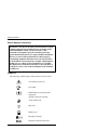
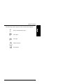
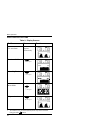
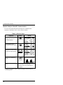
OPERATOR’S MANUAL
NPB-70
Handheld Capnograph
MANUEL DE L’UTILISATEUR
NPB-70
Capnograph Portatif
GEBRAUCHSANWEISUNG
NPB-70
Tragbarer Kapnograph
MANUAL DEL OPERADOR
NPB-70
Capnógrafo portátil
MANUAL PER L’UTENTE
NPB-70
Capnografo Palmare
Caution: U.S. Federal law restricts this device to sale by or on the order of a physician.
To contact Mallinckrodt, Inc. representative: In the United States, call 1-800-635-5267; outside the
United States, call your local Mallinckrodt representative.
© 1999 Mallinckrodt Inc. All rights reserved. 061233A-0899
Mallinckrodt Inc.
675 McDonnell Boulevard
PO. Box 5840
St. Louis, MO 63134
Tel 314.654.2000
Toll Free 1.800.635.5267
Mallinckrodt
Europe BV
Hambakenwetering 1
5231 DD ‘s-Hertogenbosch
The Netherlands
Tel. +31.73.6485200
Nellcor Puritan Bennett
4280 Hacienda Drive
Pleasanton, CA 94588
Nellcor Puritan Bennett Inc. is a wholly owned subsidiary of Mallinckrodt, Inc.
Nellcor and Nellcor Puritan Bennett are trademarks of Mallinckrodt Inc.
To obtain information about a warranty, if any, for this product, contact
Mallinckrodt Technical Services or your local Mallinckrodt representative.
Microstream and FilterLine are trademarks of Oridion Medical Ltd.
Capnography covered by one or more of the following U.S. Patents and foreign
equivalents: 4,755,675; 5,063,275; 5,300,859, 5,657,750.
OPERATOR’S MANUAL
Handheld Capnograph
Notice: Purchase of this instrument confers no express or implied license
under any Oridion Medical patent to use the instrument with any accessory
that is not manufactured or licensed by Oridion Medical Ltd.
The following are trademarks of Oridion Medical Ltd.: Microstream and
FilterLine.
Capnography covered by one or more of the following U.S. patents and
foreign equivalents: 4,755,675; 5,063,275; 5,300,859, 5,657,750.
CI04561D
TABLE OF CONTENTS
Contents
List of Figures
List of Tables
CONTENTS
SAFETY INFORMATION..................................................... 1
WARNINGS ...............................................................................1
General ................................................................................1
MRI Scanning ......................................................................2
Alarms..................................................................................2
Fire Hazard ..........................................................................3
Electrical ..............................................................................3
Electro Magnetic Interference..............................................4
SYMBOLS..................................................................................4
INTRODUCTION ................................................................. 7
MONITOR FEATURES ..............................................................7
OVERVIEW ......................................................................... 9
PRINCIPLES OF OPERATION .................................................9
Microstream EtCO2 Circuits ...............................................10
DISPLAYS, CONTROLS, AND CONNECTORS .....................12
INITIAL SETUP ................................................................. 15
POWER REQUIREMENTS .....................................................15
Battery and Power Usage ..................................................16
Battery Pack.......................................................................16
UNPACKING AND INSPECTION ............................................18
Components ......................................................................18
Optional Accessories .........................................................19
START-UP AND SELF-TEST ..................................................20
Preparation ........................................................................20
Initialization ........................................................................21
MEASURING MODE................................................................22
HANDHELD CAPNOGRAPH QUICK GUIDE.........................23
CIRCUITS.......................................................................... 25
MICROSTREAM EtCO2 CIRCUITS .........................................25
Basic Principles..................................................................25
iii
Table of Contents
BASIC OPERATION..........................................................27
DATA DISPLAY SCREENS.....................................................27
CO2 Waveform ..................................................................28
CO2 Trends ........................................................................28
Meter Mode........................................................................29
Graphic Display Screen Contrast.......................................29
DISPLAYED DATA OPTIONS .................................................30
ALARM FUNCTIONS...............................................................31
Alarms................................................................................31
ALARM LIMITS MENU ............................................................33
Alarm Silence.....................................................................34
ALARM SILENCE/STANDBY MENU......................................35
INSTRUMENT SETTINGS MENU...........................................36
Instrument Settings Menu Parameters ..............................36
User-defined Parameters...................................................37
Changing Instrument Settings ...........................................38
Institutional Settings...........................................................39
STANDBY ................................................................................39
COMMUNICATION INTERFACE.......................................41
COMMUNICATION ADAPTER................................................41
COMMUNICATION OPTIONS TO A PRINTER AND PC........42
Screen................................................................................42
Tabular Trend (5s)/(1m) ....................................................43
Graphic Trend ....................................................................44
Trend History .....................................................................45
Tabular Trend (14 Hr) ........................................................47
Monitor Setup for Printer/PC Communication....................48
COMMUNICATION INTERFACE TO A PRINTER ..................49
Printer Setup ......................................................................49
PRINTING ................................................................................52
COMMUNICATION INTERFACE TO A PC .............................53
Transferring the Data to the PC.........................................53
Downloading the Data........................................................53
TROUBLESHOOTING.............................................................54
ADDITIONAL INFORMATION .................................................55
Ordering the Seiko DPU-414 Printer .................................55
Technical Support for the Monitor......................................55
Technical Support for the Seiko Printer .............................55
iv
Table of Contents
TROUBLESHOOTING....................................................... 57
ALARMS AND MESSAGES.....................................................57
Alarm and Message Priorities............................................57
Warnings............................................................................57
Cautions.............................................................................59
Advisory Messages............................................................60
Silent Advisories ................................................................61
TROUBLESHOOTING GUIDE ................................................63
MAINTENANCE ................................................................ 65
PERIODIC MAINTENANCE ....................................................65
SERVICE .................................................................................66
CLEANING...............................................................................66
CO2 CALIBRATION CHECK....................................................66
RETURNING THE MONITOR .................................................69
TECHNICAL ASSISTANCE.....................................................69
SPECIFICATIONS............................................................. 71
PHYSICAL ...............................................................................71
Size ....................................................................................71
Weight (including battery pack) ........................................71
Noise Emission ..................................................................71
ENVIRONMENTAL ..................................................................71
Temperature ......................................................................71
Relative Humidity ...............................................................71
Pressure and Altitude (for operating and storage).............71
SAFETY STANDARDS ............................................................72
PERFORMANCE .....................................................................72
POWER SPECIFICATIONS ....................................................73
External Power Source ......................................................73
Internal Power Source .......................................................73
COMPONENTS AND USER INTERFACE ..............................73
Displays .............................................................................73
Controls and Indicators ......................................................74
Connections .......................................................................74
v
Table of Contents
List of Figures
Figure 1: Monitor Front and Side View........................... 12
Figure 2: Monitor Rear View........................................... 13
Figure 3: Initialization Screen ........................................ 21
Figure 4: Quick Guide Adhesive Label........................... 23
Figure 5: Monitor Display Screen and LEDs.................. 27
Figure 6: Tabular Trend Printout .................................... 43
Figure 7: Graphic Trend Printout.................................... 44
Figure 8: Trend History Printout ..................................... 46
List of Tables
Table 1: Packaged monitor .......................................... 18
Table 2: Display Screens.............................................. 30
Table 3: Factory Default Alarm Range Values ............ 32
Table 4: Alarm Limits.................................................... 33
Table 5: Alarm Silence/Standby ................................... 35
Table 6: Instrument Settings Menu Parameters .......... 36
Table 7: Changing Instrument Settings........................ 38
Table 8: Institutional Settings ....................................... 39
Table 9: Print Options................................................... 42
Table 10: Monitor Setup ................................................. 48
Table 11: Dip Switch Settings ........................................ 50
Table 12: Start/Stop Printing Options............................. 52
Table 13: COM Property Settings .................................. 53
Table 14: Troubleshooting Examples ............................ 54
Table 15: Warning Messages ........................................ 58
Table 16: Caution Messages.......................................... 59
Table 17: Advisory Messages ........................................ 60
Table 18: Silent Advisory Messages .............................. 61
Table 19: Troubleshooting Guide................................... 63
Table 20: Accessing the Service Mode.......................... 65
Table 21: CO2 Calibration Check ................................... 67
vi
SAFETY INFORMATION
Warnings
Symbols
To use the monitor correctly and safely, carefully read this operator’s
manual and the Directions for Use for the Microstream EtCO2 circuits.
Use of the monitor requires full understanding and strict observation of
these instructions, precautionary information in boldface type, and
specifications.
WARNINGS
General
WARNING: If uncertain about the accuracy of any
measurement, check the patient’s vital signs by alternate
means, then make sure the monitor is functioning correctly.
WARNING: To ensure patient safety, do not place the monitor
in any position that might cause it to fall on the patient.
WARNING: Carefully route patient cabling (FilterLine) to
reduce the possibility of patient entanglement or strangulation.
WARNING: Do not lift the monitor by the FilterLine as it
could disconnect from the monitor, causing the monitor to fall
on the patient.
WARNING: To ensure accurate performance and prevent
device failure, do not expose the monitor to extreme moisture,
such as rain.
1
Safety Information
WARNING: CO2 readings and respiratory rate readings can
be affected by certain ambient environmental conditions and
certain patient conditions.
Caution: The monitor is a prescription device and to be
operated by qualified healthcare personnel only.
Caution: Connect the gas outlet to a scavenging system when
using the monitor with N2O or other anesthetic agents.
MRI Scanning
WARNING: Do not use the monitor during magnetic
resonance imaging (MRI) scanning.
Alarms
WARNING: Do not silence the audible alarm if patient safety
may be compromised.
WARNING: Always respond immediately to a system alarm
since the patient may not be monitored during certain alarm
conditions.
WARNING: Before each use, verify that the alarm limits are
appropriate for the patient being monitored.
WARNING: Check the audible alarm silence duration before
temporarily silencing the audible alarms.
2
Safety Information
WARNING: The monitor is not to be used as an apnea
monitor. (An apnea message appears if a valid breath has not
been detected for 15 seconds [neonatal mode] or 30 seconds
[adult mode]. This indicates the time elapsed since the last
valid breath and is not a diagnosis.)
Fire Hazard
WARNING: When using the monitor with flammable gases
or anesthetics, such as high concentrations of oxygen or
nitrous oxide, connect the gas outlet to a scavenger system.
Electrical
WARNING: Electric shock hazard. The monitor’s cover is to
be removed only by qualified service personnel. There are no
user-serviceable parts inside.
WARNING: To ensure patient electrical isolation, connect
only to other equipment with circuits that are electrically
isolated.
WARNING: Use only the medical-grade AC adapter
provided by the manufacturer. If in doubt about the integrity
of the mains supply connection, operate the monitor from its
internal battery pack.
WARNING: Do not connect to a printer or to a PC unless
using the Communication Adapter provided by the
manufacturer as an optional accessory. The Printer and PC
(when connected to the patient through the Communication
Adapter) must be distanced from the patient environment by
at least 1.5 m.
3
Safety Information
Electro Magnetic Interference
WARNING: This device has been tested and found to comply
with the requirements for medical devices according to the
standard EN60601-1/1990, A1/1993, A2/1995. These
standards are designed to provide reasonable protection
against harmful interference in a typical medical installation.
However, because of the proliferation of radio-frequency
transmitting equipment and other sources of electrical noise
in the healthcare environments (for example, cellular phones,
mobile two-way radios, electrical appliances), it is possible
that high levels of such interference due to close proximity or
strength of a source, may result in disruption of performance
of this device.
SYMBOLS
The following symbols appear on the monitor and accessories:
See Instructions for Use
Gas Outlet
Defibrillator-proof typeType BF
equipment
(patient electrically isolated)
Audio Alarms Off
Plug Icon
Battery Icon
Breaths per minute
End tidal carbon dioxide value
4
Safety Information
The following symbols appear on the Communication Adapter:
Serial communications port
DC output
DC input
Printer interface
PC interface
5
INTRODUCTION
Monitor Features
This manual provides directions for setup and operation of the handheld
capnograph monitor.
The device is a handheld capnograph that continuously monitors end
tidal carbon dioxide (EtCO2) and respiratory rate. The monitor is for
attended monitoring only and must be used in the continuous presence of
a qualified healthcare provider. It is intended for use in any environment
where continuous, noninvasive monitoring of these parameters is
desired, including hospital and mobile use (when protected from
excessive moisture such as direct rainfall).
The monitor is intended for use on adult, pediatric, and infant/neonatal
patients.
MONITOR FEATURES
• Capnograph in a small, handheld, lightweight monitor.
• Measures and displays EtCO2, and respiration rate, in one graphic
and two digital displays.
• Displays CO2 waveforms and trends.
• Utilizes a wide range of Microstream EtCO2 circuits and adapters
for all applications.
• Operates on main line power or a rechargeable Nickel Metal
Hydride battery pack.
• Employs audible and visual alarm warnings for monitored
parameters and instrument malfunctions.
• Provides user selectable language options: English, French,
German, Spanish.
• Displays EtCO2 values in mmHg, kPa or Vol%.
• Provides output for printer or PC.
7
OVERVIEW
Principles of Operation
Displays, Controls, and Connectors
The monitor incorporates Oridion’s Microstream capnography
technology.
PRINCIPLES OF OPERATION
The monitor uses Microstream non-dispersive infrared (IR)
spectroscopy to continuously measure the amount of CO2 during
every breath, the amounts of CO2 present at the end of exhalation
(EtCO2) and during inhalation (FiCO2), and the Respiratory Rate.
Infrared spectroscopy is used to measure the concentration of
molecules that absorb infrared light. Because the absorption is
proportional to the concentration of the absorbing molecule, the
concentration can be determined by comparing its absorption to that
of a known standard.
The Microstream EtCO2 circuits deliver a sample of the inhaled and
exhaled gases from the ventilator circuit or directly from the patient
into the monitor for CO2 measurement. Moisture and patient
secretions are extracted from the sample while maintaining the shape
of the CO2 waveform.
The 50 ml/min. low sampling flow rate reduces liquid and secretion
accumulation, thus the sample flow is not obstructed, even in humid
ICU environments.
Once inside the Microstream CO2 sensor, the gas sample goes
through a microsample cell (15 microliters). This extremely small
volume is quickly flushed, allowing for fast rise time and accurate
CO2 readings, even at high respiration rates.
The Microbeam IR source illuminates the microsample cell and the
reference channel. This proprietary IR light source generates only
the specific wavelengths characteristic of the CO2 absorption
spectrum. Therefore, no compensations are required when different
9
Overview
concentrations of N2O, O2, anesthetic agents, and water vapor are
present in the inhaled and exhaled breath. The radiation that passes
through the microsample cell and the radiation that passes through
the reference channel are measured by the IR detectors.
The microcomputer in the monitor calculates the CO2 concentration
by comparing the signals from both channels.
Microstream EtCO2 Circuits
— Microstream FilterLine
The Microstream FilterLine has four active elements
that work together to offer a solution to the problems
that have previously posed challenges to capnography
in ICU, emergency, and transport applications. These
elements are described below.
* Hydrophobic filter
The hydrophobic filter is located at the end of the
sample line that is closest to the capnograph. This
filter strips the remaining water vapor from the gas
sample while keeping a laminar flow of the gas.
This laminar flow minimizes distortion of the CO2
waveform.
This filter is made of 0.45µ hydrophobic porous
media that reduces biological contaminants.
* Drying element
The drying element is a tube made of a synthetic
material that is chemically stable and has high water
absorption. This material allows the water vapor to
pass outside the tube, thereby adjusting the humidity
inside the FilterLine close to the level of humidity in
the ambient air.
10
Overview
* Sample line
The sample line has low dead space due to its small
internal diameter. This provides a sharp waveform
and an accurate CO2 reading at high breath rate per
minute. The sample line is not affected by gases
and anesthetic agents in the operating room
environment.
* FilterLine Recognition Safeguard
When the FilterLine is attached to the monitor, the
FilterLine Recognition Safeguard (FRS) identifies
the FilterLine and activates the monitor, thus
enabling it to take a measurement.
— Microstream Airway Adapter
The Microstream airway adapter design provides
multiple channels for the sampled air from the airway
minimizing the possibility of water infiltration or line
blockage. These multiple channels allow uninterrupted
monitoring for all adapter orientations and in all
applications. The Microstream airway adapter provides
optimal performance in all directions and is seldom
disabled by secretions or liquids.
11
Overview
DISPLAYS, CONTROLS, AND CONNECTORS
Figure 1: Monitor Front and Side View
The numbered labels in Figure 1 are described below.
1. ON/OFF Switch
2. Alarm Bar
3. Digital Display of EtCO2
and Respiration Rate
4. Graphic Display
5. Contrast/Changes Value
Button
*6. Next/Menu Button
7. Battery Pack
*6+8 = Data Transfer ON/OFF
12
*8. Event/Home Button
9. Power Supply/ Communication
Adapter Port
10. Alarm Silence/Alarm Silence
Menu Button
11. Alarm Silence Indicator
12. Gas Outlet
13. Photo Resistor
14. FilterLine Input Connector
Overview
1
2
3
4
5
Figure 2: Monitor Rear View
The numbered labels in Figure 2 are described below.
1. Clamp Adapter
2. Space for Quick Guide
Adhesive Label
3. Serial Number Label
4. Battery Pack Release Button
5. Battery Pack
13
INITIAL SETUP
Power Requirements
Unpacking & Inspection
Start-up and Self-Test
Measuring Mode
Handheld Capnograph Quick Guide
POWER REQUIREMENTS
The monitor operates on batteries or on AC power. It is equipped
with a rechargeable Nickel Metal Hydride battery pack. When a
power outlet is available, use the medical grade AC adapter
provided with the monitor.
Before using the monitor in the field, ensure that the battery pack
is fully charged. (At the measuring mode, check that the battery
icon at the right side of the graphic display is full.)
Note: If the battery is not fully charged, the icon may first show
as full and after a short period of time will drop to indicate
the real charge level.
A fully charged battery pack provides between three to six
operating hours, depending on power management (refer to Table
6 for a description of the power management options).
WARNING: Use only the medical-grade AC adapter
provided by the manufacturer. If in doubt about the
integrity of the mains supply connection, operate the
monitor from its internal battery pack.
WARNING: To ensure patient electrical isolation,
connect only to other equipment with circuits that are
electrically isolated.
15
Initial Setup
Battery and Power Usage
If power is lost when the monitor is operating from AC power,
the monitor automatically switches to its internal battery pack for
power.
at the bottom right side of the graphic display
A plug-shaped icon
is displayed when the monitor operates from an external power
source and the battery pack is fully charged. A battery-shaped icon
is displayed when the monitor operates from the battery pack. The
battery icon will show the battery pack’s approximate charge level.
An advisory message, Battery ⇓ !, appears when approximately 40
minutes of battery charge remains. A caution message Battery ⇓ !!
appears when approximately 15 minutes of charge time remains.
While the monitor is connected to AC power, the battery pack can be
replaced without interrupting monitoring.
Battery Pack
Before using the monitor for the first time, it is recommended to
charge and discharge the battery 3 times to ensure full battery
capacity.
Internal Recharge Function
Caution: Do not attempt to disassemble the battery pack. It is a
sealed unit and has no serviceable parts inside.
When the monitor is connected to an external power source (even if
the monitor is in the “OFF” position), the battery pack charges
automatically. During charging, if the instrument is on, the batteryshaped icon displays a filling pattern. It takes approximately 4.5
hours to fully charge an empty battery pack. Additional battery packs
can be purchased from your local distributor.
The recommended temperature for battery charging is between 5ºC
to 45ºC.
16
Initial Setup
Important! The following information relates to the safe
handling, storage, and disposal of the monitor battery pack.
Battery Testing
The battery pack charge level should be tested before each use by
observing the level on the battery icon after self-test. For a correct
reading, wait for the battery charge level to stabilize. It is
recommended to replace or recharge the battery pack when the
advisory message Battery appears on the graphic display screen
(refer to the Troubleshooting section).
Handling
• Do not immerse the battery pack in water; it may malfunction.
• Only recharge the battery pack in the monitor or use a charger
provided by your local distributor to avoid possible heating,
burning or rupture of the battery pack.
Storage
• Short-term storage (one month or less): The battery pack has an
automatic discharge feature. You must periodically check the
charge level of the battery pack.
• Long-term storage (6 months or more): The battery pack must be
stored in a cold, dry area. Its charge decreases over time. To
restore the battery pack to full power, charge and discharge it
three times before use. Long-term storage without charging the
battery, may degrade the battery capacity.
Disposal
• Do not dispose of the battery pack in a fire; it may explode.
• Be sure to follow local governing ordinances and recycling
instructions regarding disposal or recycling of batteries.
17
Initial Setup
UNPACKING AND INSPECTION
Components
1. Remove the monitor and the circuits from the box carefully.
2. Check that the following items are included (Table 1):
Table 1: Packaged monitor
Contents of Package
Qty
Handheld Capnograph Monitor
1
Microstream EtCO2 Circuit Kit
1 kit
AC Adapter
1
AC Adapter Power Cable
1
Operator’s Manual
1
Quick Guide Adhesive Label
1
3. Inspect each component. If the package is damaged or any
component is missing, contact your local representative.
18
Initial Setup
Optional Accessories
The following items are available from your local distributor for use
with the monitor:
• Carrying Case
• Clamp
• Rechargeable Battery Pack
• External Battery Charger
• Battery Pack Carrying Pouch
• Communication Adapter Kit (for interface to PC or printer)
• Calibration Gas Kit
• Service Manual
Important! To protect the unit, the manufacturer
recommends using either the carrying case or the clamp,
depending on the type of application.
19
Initial Setup
START-UP AND SELF-TEST
WARNING: Do not lift the monitor by the FilterLine as it
could disconnect from the monitor causing it to drop on
the patient.
WARNING: To ensure patient safety, do not place the
monitor in any position that might cause it to fall on the
patient. As with all medical equipment, carefully route the
FilterLine cable to reduce the possibility of patient
entanglement or strangulation.
Caution: The monitor is intended only as an adjunct in patient
assessment. It must be used in conjunction with clinical signs and
symptoms.
Caution: The monitor is a prescription device and is to be
operated by qualified healthcare providers only.
Caution: Only use Microstream EtCO2 circuits to ensure that the
monitor functions properly.
Caution: Connect the gas outlet to a scavenging system when
using the monitor with N2O or other anesthetic agents.
Preparation
Prior to start-up:
1. Slide open the input connector’s shutter and connect the
appropriate Microstream EtCO2 circuit.
2. Connect the appropriate Microstream EtCO2 circuit to the
patient as described in the Directions for Use.
Note: When the monitor is handheld, it is recommended to use it
with its carrying case (available as an optional accessory).
20
Initial Setup
When the monitor is used in stationary applications, it
is recommended to secure it with the clamp (available
as an optional accessory).
Initialization
Caution: If any monitor response does not seem appropriate, do
not use the monitor. Instead, contact your local distributor.
Caution: Immediately after power-up, confirm that all display
segments and icons function.
1. Turn on the monitor by sliding the ON/OFF switch to the ON
position.
2. Verify that the monitor is working properly. Proper working
condition is verified by completing the power-on self-test
described in the following step.
When turned on, the
initialization screen appears,
the monitor automatically
performs a self-test and the
self-test bar fills (for up to 15
seconds). The display and
alarm functions are tested
activating the LCD, alarm bar,
seven segment displays, alarm
silence indicator, and buzzer.
In this mode all alarms are
disabled. (Refer to Figure 3.)
Figure 3: Initialization
Screen
During Self-Test, the EtCO2 and Respiration Rate LED’s show
dashes. When the monitor is Ready and the FilterLine circuit is
connected, the dashes in the EtCO2 and Respiration Rate LED’s are
replaced by numeric values. If the FilterLine circuit is not connected
to the monitor, dashes will appear on the LED's.
21
Initial Setup
MEASURING MODE
In Measuring Mode, the monitor is measuring, displaying, and
storing event data, or printing data that has been stored in its
memory.
While taking measurements, the monitor displays EtCO2 and
respiration rate readings on the digital displays. The waveform and
other information, according to the selected screen; (see the Basic
Operation section of this manual) are shown on the graphic display.
The monitor begins measuring EtCO2 after recognizing one breath
(after monitor power-up or after exiting Standby). The monitor
recognizes two breath measurement ranges:
Valid breath: values ≥ 7.5 mmHg (for adult mode) or ≥ 5.0 mmHg
(for neonatal mode)
Low readings breath: values < 7.5mmHg (for adult mode) or
< 5.0 mmHg (for neonatal mode)
Note: If the first breath the monitor recognizes is a Low
readings breath, the monitor will not display nor emit
warning signals and an APNEA message will not appear.
If the values go above 7.5 mmHg (for adult mode) or 5.0
mmHg (for neonatal mode), and then fall below these
ranges, the monitor will display an APNEA message and
emit warning signals (see the Troubleshooting section of
this manual).
EtCO2 readings between 3.0-7.0 mmHg (adult mode) or 3.0-5.0
mmHg (neonatal mode) appear as numerical values on the EtCO2
LED’s. Readings <3.0mmHg show as 0 (zero) on the LED’s.
The monitor begins measuring Respiration Rate after two valid
breaths.
The waveform appears on the graphic display for all EtCO2 values.
22
Initial Setup
HANDHELD CAPNOGRAPH QUICK GUIDE
1. Connect only Microstream EtCO2 circuits to the monitor.
2. Battery pack operation: First, switch the monitor ON, check
that the battery pack is charged (at measuring mode, check
that the battery icon at the right side of the graphic display is
full).
AC operation: Connect the AC adapter to the monitor and
plug the cord into the mains power supply. Switch the monitor
ON. Check that the battery icon displays a filling pattern or
the plug icon shows.
(Refer to Figure 4 for all button functions.)
3. Adjust the parameters in the Alarm Limits menu, Instrument
Setup menu, and Alarm Silence menu to the values
appropriate to the patient’s condition.
Power On
Short Press
Long Press
Changes Displays / Accesses
Selects Parameters Menus
Home /
Event Mark
Erase Trend
Changes
Values / Contrast
Sound ON / OFF
Quick Scroll
Accesses
Alarm Menu
Data Transfer
ON / OFF
Figure 4: Quick Guide Adhesive Label
23
CIRCUITS
Microstream EtCO2 Circuits
MICROSTREAM EtCO2 CIRCUITS
FilterLines (sampling lines) and Airway Adapters comprise the
Microstream EtCO2 family of circuits for EtCO2 monitoring.
Basic Principles
Caution: Before use, carefully read the Microstream EtCO2
Circuits Directions for Use.
Caution: Only use Microstream EtCO2 Circuits to ensure the
monitor functions properly.
Caution: Do not reuse, sterilize, or clean Microstream EtCO2
Circuits as they are designed for single patient use.
Caution: Dispose of Microstream EtCO2 Circuits according to
standard operating procedures or local regulations for the
disposal of contaminated medical waste.
When choosing Microstream EtCO2 Circuits, the following should
be considered:
•
Patient’s breathing situation (intubated or non-intubated)
•
Mode of ventilation (if ventilated)
•
Duration of use
•
Patient’s weight
For further information, please contact your local representative.
Select the appropriate Microstream EtCO2 FilterLine and/or Airway
Adapter and connect it to the monitor before attaching it to the
patient’s airway. Be sure to follow Microstream EtCO2 Circuits’
Directions for Use for proper connection.
25
BASIC OPERATION
Data Display Screens
Displayed Data Options
Alarm Functions
Alarm Limits Menu
Alarm Silence/Standby Menu
Instrument Settings Menu
Standby
DATA DISPLAY SCREENS
In Measuring Mode, the monitor constantly measures and displays
the CO2 waveform, EtCO2, and respiratory rate (bpm) values.
Note: For both neonatal and adult patients, the EtCO2 displayed
on the LED Numeric Displays represents the maximum
value during the last 15 seconds (updated every 5
seconds). The EtCO2 is displayed from the first breath.
The EtCO2 warning is according to the 7-Segment value.
The respiratory rate and EtCO2 values are constantly shown in the
LEDs. Waveform or Trends are shown in the graphic display
depending on the selected display screen (see Figure 5 and Table 2).
Power icons, advisories, warnings, or cautions appear superimposed
over the data display.
At any time during the measuring mode, the user can mark a special
and a short duration tone sounds. The
event by a short press of
event is stored in the monitor’s memory and will appear on the data
printout marked by an * on the tabular trend printout and a vertical
line on the graphic trend printout.
Figure 5: Monitor Display Screen and LEDs
27
Basic Operation
There are four data display screens (Table 2):
• CO2 Waveform
• CO2 Trend, 30 minutes
• CO2 Trend, 8 hours
• Meter Mode
CO2 Waveform
The CO2 waveform screen displays a real-time CO2 waveform, and
respiration rates. (The end tidal CO2 and bpm values are shown
simultaneously on the digital displays.)
CO2 Time Base
The time base is the period of time captured on the display. The time
base default values are:
•
6 seconds for Adult Mode
•
3 seconds for Neonatal Mode
During periods of high respiration rates, the display will
automatically depict the shorter time base to avoid compression of
the waveform.
The time base appears at the top right side of the graphic screen as a
Temporary Silent Advisory and is shown for 5 seconds each time the
instrument enters the CO2 waveform screen or after every change of
the time base. The instrument also automatically changes the time
base.
CO2 Trends
•
The trends graphs represent trend data of the last 30 minutes
or 8 hours (15-second or 4-minute resolution respectively).
The trends are shown in the CO2 scale selected by the user.
The tabular trend data for 14 hours (5-second resolution) is
relevant for the print/PC option only.
During the 14-hour tabular trend period, the data of (up to)
the last 100 patients are stored. (A new patient is defined
each time the monitor is turned on/off or enters Standby.)
28
Basic Operation
Note: In the case of the “Autoscale Option”, the CO2 scale
is that of the maximum range.
•
The FiCO2 value is shown as light pixels at the bottom of
the trends graph.
•
When the monitor is turned ON a trend data border will
mark the end of the previous trend. A trend data border will
also appear after exiting Standby and returning to measuring
mode.The trend data border is a vertical line on the graph.
An event will appear on the tabular trend printout marked by
an “*”and as a vertical line on the graphic trend printout.
•
When you enter a trend display, a temporary message “Press
To Erase” appears for 3 seconds. This allows you to
erase all old trends. This message will not appear during an
alarm but the trend erase function will still work.
•
The real-time EtCO2 and respiration rate values are shown
on the digital display.
Meter Mode
The Meter Mode screen displays the EtCO2 value on the left side of
the screen and the respiration rate on the right side of the screen.
This mode is recommended in the following cases:
•
When the power management is at Low (see Table 6).
•
When the monitor display is exposed to direct sunlight
affecting the digital display reading.
Graphic Display Screen Contrast
The LCD contrast intensity can be adjusted during Measuring
Mode. To adjust the contrast, press the contrast button
press the right side for a darker contrast and the left side for a
lighter contrast.
;
The photo resistor senses the ambient light intensity and accordingly
switches the backlight ON or OFF during Normal power
management setting.
29
Basic Operation
DISPLAYED DATA OPTIONS
Table 2: Display Screens
To View
Press
CO2 waveform
Appears
automatically
Result
30 min. - CO2 Trend
1st short press
8 hr. - CO2 Trend
2nd short press
Meter Mode
3 rd short press
CO2 waveform*
4th short press
∗
30
To return to CO2 waveform (Home) from any screen or menu:
Long press the
button.
Basic Operation
ALARM FUNCTIONS
WARNING: Do not turn off the audible alarm if patient safety
could be compromised. Pressing the alarm silence button turns
the audio alarms OFF and turns the alarm silence icon LED
indicator ON. In this condition there will be no audible alarms in
the event of adverse patient conditions.
The monitor has four levels of alarms. For full details on alarms, see
the Troubleshooting section of this manual.
Alarms
Warnings are the highest level of alarms to alert the user that the
patient’s condition is beyond predefined limits. Alarms can be set
from the Alarm Limits menu (see Table 4). The monitor has the
following alarms with adjustable level settings:
•
EtCO2 high and low levels
•
FiCO2 high level
Apnea is a message alerting the user when no valid breath is detected
after a predetermined time depending on the patient mode: 15
seconds for infant/neonatal patients and 30 seconds for adult
patients. The APNEA message appears only after warm-up and the
monitor measures one valid breath. The apnea alarm stops after the
monitor recognizes one valid breath.
The following alarms alert the user of the instrument’s status or
malfunction:
•
Caution messages (audio and visual)
•
Advisory messages (audio and visual)
•
Silent advisory messages (visual)
Factory Default Alarm Range Values
Table 3 lists the default values of the various alarm ranges. These
values can be changed from the Alarm Limits menu.
31
Basic Operation
Caution: The monitor will revert to its default alarm limit
settings at power on, power interruption, and when changing the
patient mode.
Note: The user can have the factory default values of the alarm
range permanently changed (see Institutional Settings). For
further information, call your local distributor.
The CO2 values in the table are shown in mmHg. The values in
parentheses correspond to the kPa and Vol% (at sea level).
Table 3: Factory Default Alarm Range Values
Parameter
Adult
Default
Neonate
Default
Maximu
m
Minimum
EtCO2 high
EtCO2 low
FiCO2 high
50 [6.7]
15 [2.0]
8 [1.1]
50 [6.7]
15 [2.0]
8 [1.1]
100 [13.0]
99 [12.9]
99 [12.9]
5 [0.5]
0 [0.0]
2 [0.1]
See the Instrument Settings Menu section for a list of parameters
that are set by the user and stored in the memory.
CO2 Scale Options
•
0-50 mmHg (0-7 kPa or Vol%)
•
0-99 mmHg (0-14 kPa or Vol%)
•
Autoscale
- Changes from lower to higher scale after 12 consecutive
breaths with EtCO2 values larger than low level scale limit.
- Changes from higher to lower scale after 12 consecutive
breaths with EtCO2 values smaller than low level scale
limit.
Whenever autoscale is selected, the trend scale (and printed
graphic scale) will be the high-level scale limit.
The Factory Default CO2 is 0-50 mmHg. The CO2 scale
option will not return to the Factory Default after being
changed by the user. See User-defined Parameters.
32
Basic Operation
ALARM LIMITS MENU
Table 4 explains how to access the Alarm Limits menu and to
change the parameters and values.
Table 4: Alarm Limits
Objective
To access the Alarm
Limits menu from any
measuring display*
Action
Result
long press
To change the patient
mode**
short press
To access any displayed
parameter
short press
To change the
parameter’s value
short press/long
press***
To exit and return to
Measuring Mode (at
any point in the Alarm
Limits menu)
long press
*
If after 15 seconds no action is taken, the display returns to
measuring mode.
**
The neonatal mode is recommended when a patient’s breath rate is
>50 breaths per minute. Neonates often have a respiration rate >50
breaths per minute.
*** Long press: the value skips by multiples of 5 (except for FiCO2).
33
Basic Operation
WARNING: Make sure the patient type and CO2 scale are
appropriate for each patient. An error in the patient type can
cause incorrect alarm limits or incorrect CO2 readings. If the
CO2 scale is not appropriate the waveform will be either
incomplete or small.
Alarm Silence
Alarms can be temporarily silenced. A short press of the alarm
silence button
will temporarily disable the audible alarm for a
pre-set period of time and the alarm silence indicator will be lit. The
audible alarm can be reactivated with a short press of the alarm
silence button. The default setting is 2 minutes. You can change this
setting from the Alarm Silence/Standby menu (Table 5).
From the Alarm Silence menu, you can choose to permanently
disable a specific audio alarm or all audio alarms.
Whenever an alarm is disabled indefinitely, the alarm silence
will be lit on the front panel and the Alarm Silence icon
indicator
will appear on the right side of the graphic display with the
appropriate label.
• ALL
All the alarms are turned off.
• CO2
CO2 alarms (including apnea message) are turned off.
Note: When any alarm is disabled, a single caution burst can
sound once every three minutes if opted through
Institutional Settings (refer to Institutional Settings in this
chapter). If an alarm condition occurs when any
corresponding alarm is disabled, a message is generated on
the monitor display.
34
Basic Operation
ALARM SILENCE/STANDBY MENU
Table 5: Alarm Silence/Standby
Objective
To access the Alarm
Silence/Standby menu
from any measuring
display*.
Action
Result
long press
To change the silence
period**.
short press
To access any
displayed parameters.
To change the setting
of the selected
parameter.
To exit and return to
measuring display (at
any point in the Alarm
Silence/Standby
menu).
short press
short press
long press
* If after 15 seconds no action is taken, the display returns to
measuring mode.
** Alarm silence limits are from 1-2 minutes.
35
Basic Operation
INSTRUMENT SETTINGS MENU
Instrument Settings Menu Parameters
Table 6 explains the user-defined parameters that can be set from the
Instrument Settings menu.
Table 6: Instrument Settings Menu Parameters
Parameter
User options
CO2 units
mmHg, Vol%, kPa
Power Mgmt Full Display backlight on and 7 segment
(Management)
LEDs at high intensity.
Normal - Display backlight on and 7 LEDs
segments at normal intensity.
Low Backlight and 7 LEDs segment off.
Note: During AC power, the monitor backlight is
on all the time but the power management mode
setting will continue to display the current
selection; full, normal or low.
Print
Screen – the current display is printed
Graphic Trend – real time trend is printed in a
graphic form.
Trend History – stored trend is printed in graphic
and tabular form.
Tab. Trend (5s) Real time trend data is printed
in tabular form (every 5 seconds).
Tab. Trend (1m) Real time trend data is printed
in tabular form (every minute).
Tab. Trend (14h) – with a resolution of
5 seconds. Stored trend is communicated in
tabular form.
36
Language
English, French, German, Spanish
Check Cal.
See the Maintenance section, “CO2 Calibration
Check.” (Table 21).
Basic Operation
User-defined Parameters
The following parameters will not return to their defaults after being
changed by the user. These parameters are stored in the memory of
the monitor until the next time they are changed by the user.
Note: When changing any parameter below, wait approximately
10 seconds before turning the monitor off. If you turn off
the monitor immediately after changing the parameter, the
new setting may not be saved.
•
CO2 Waveform Scale
•
CO2 Waveform Units
•
CO2 Mode (Patient)
•
Print Option
•
Language
•
Power Management Option
37
Basic Operation
Changing Instrument Settings
Use this menu (Table 7) to change the instrument settings.
Table 7: Changing Instrument Settings
Objective
To access the Instrument
Settings menu (first access
the Alarm Limits menu
from any measuring
display by one long press
and then the Instrument
Settings with the 2nd long
press)*.
Action
Result
long press (x2)
To change the CO2 scale
option.
short press
To access any displayed
parameter.
short press
To change the parameter’s
setting.
short press
Exit and return to the
Measuring Mode at any
point in the Instrument
Settings menu.
Exit and return to the
Alarm Limits menu.
∗
38
long press
long press
If after 15 seconds no action is taken, the display returns to
measuring mode.
Basic Operation
Institutional Settings
The factory default parameter settings in Table 8 can be changed by
the manufacturer’s service representative or by referring to the
Handheld Capnograph Service Manual.
Table 8: Institutional Settings
Parameter
Factory Default Setting
Alarm Default Settings
See Table 3: Default
Alarm Range Values
3 Min Alert
(to remind user that alarms are
set to off)
OFF
BTPS (body temperature,
pressure, saturation assumed 37°C,
47mmHg)*
ON
* Calculations are made according to:
PCO2 = FCO2 x (Pb - 47)
Where FCO2 is the Fractional concentration of CO 2 in dry gas,
Where FCO2 = % CO2/100
Pb = the ambient pressure
PCO2 = the partial pressure of CO2 at BTPS
STANDBY
The Standby mode is an automatic or selectable function designed to
reduce power consumption and to avoid unnecessary alarms.
To set the monitor manually in the Standby mode, choose the
Standby ON option from the Alarm Silence/Standby menu (Table 5).
The Standby screen appears. A long press of any key restores the
Measuring Mode. (The Alarm Limits menu appears briefly before the
Measuring Mode but the alarms cannot be changed at this time).
The monitor will automatically enter Standby mode if, after Power
ON, no signal is registered for 10 minutes.
Note: When exiting Standby mode, the monitor reverts to the Factory
default of “All Alarms On”.
Note: The Alarm Limits settings are not changed (do not revert to
defaults) when moving to and from Standby mode.
39
COMMUNICATION INTERFACE
Communication Adapter
Communication Options to a Printer and PC
Communication Interface to a Printer
Communication Interface to a PC
Troubleshooting
Additional Information
The Handheld Capnograph (monitor) can interfaced to a Seiko DPU414 printer or to a personal computer (PC) to download real time and
trend values for EtCO2, FiCO2, and Respiratory Rate. The monitor
interfaces to the PC or Printer with the Communication Adapter Kit
(available as an optional accessory).
WARNING: When connecting the monitor to another
instrument, verify its proper operation before clinical use.
Refer to the other device’s manual for full instructions. For
further questions, contact your local distributor.
WARNING: Do not connect the monitor to a printer or to a
PC unless using the Communication Adapter Kit provided by
the manufacturer as an optional accessory.
WARNING: When using the printer/PC with main line
power, it is recommended to use a medical grade power
supply complying with the following standards: EN60601-1,
UL 2601-1, CSA C22.2 No. 601.1-M90. If the power supply is
not medical grade, the printer/PC must be placed at least 1.5
meters from the patient environment complying with
standard EN60601-1-1.
COMMUNICATION ADAPTER
The monitor has a single input/output port. During normal operating
conditions, this port is used to connect the monitor to the external
medical grade AC adapter. When printing functions or
communication to the PC are required, the port is connected to the
Communication Adapter. The Communication Adapter uses the port
as an input port to connect the monitor to the AC power supply
41
Communication Interface
and/or as an output port to connect the monitor to a printer or PC.
For further information, refer to the Communication Adapter Kit
Directions for Use.
COMMUNICATION OPTIONS TO A PRINTER AND PC
Table 9 lists and describes the options available to download
information from the monitor to either a printer and/or PC.
Table 9: Print Options
Option
Screen
Real Time
Graphic Trend
Tabular Trend
History
Tab. Trend (5s)
Tab. Trend (1m)
Tab. Trend (14
Hr)
Description
Output
The measuring mode displayed on
the screen is printed in graphic
form.
The real time trend data is printed
in graphic form.
The stored trend data is printed in
graphic and tabular form.
The real time trend data is printed
in tabular form every 5 seconds.
The real time trend data is printed
in tabular form every minute.
The stored trend data for the last 14
hours is printed in tabular form.
To printer
To printer
and PC*
To printer
To printer
and PC
To printer
and PC
To
printer**
and PC
* When downloading to a PC, the graphic will appear as garbled
data.
** It is not recommended to download 14 hour trend history to a
printer due to the large volume of data and the amount of paper
that would be required.
Screen
The Screen option prints the current data display screen (Wave form,
CO2 Trend-30 minutes, CO2 Trend - 8 hours, and Meter Mode).
42
Communication Interface
Tabular Trend (5s)/(1m)
The Tabular Trend prints EtCO2, FiCO2, and Respiration Rate in
either 1 minute or 5 second resolutions, depending on the print
option selected. After turning the unit off, the printed time is reset to
zero.
The printout includes the following data (refer to Figure 6: Tabular
Trend Printout):
• Patient data
• Alarms: Only warning messages print (Apnea, EtCO2 high,
EtCO2 low, FiCO2 high). If two or more alarms occur
simultaneously, only the alarm with the highest priority will
appear on the printout (refer to the Handheld Capnograph’s
Operator’s Manual for alarm priorities).
• Events are marked with an asterisk “*” beside the time.
• The CO2 units print according to the units selected in the
Instrument Settings menu and are indicated in the header of the
table as: M = mmHg, K = kPa, V = Vol%.
Figure 6: Tabular Trend Printout
43
Communication Interface
Graphic Trend
The Graphic Trend data prints in graphic form EtCO2, FiCO2, and
Respiration Rate values.
The printout includes the following data (refer to Figure 7: Graphic
Trend Printout):
• Patient data prints every 2 minutes
• Alarms: Only warning messages (Apnea, EtCO2 high, EtCO2 low,
FiCO2 high) print after each graph (after 5 hours). If two or more
alarms occur simultaneously, only the alarm with the highest
priority will appear on the printout (refer to the Handheld
Capnograph’s Operator’s Manual for alarm priorities).
• Time grid is drawn every 10 minutes
• Time label prints every 30 minutes
• FiCO2 values appear as white marks at the bottom of the CO2
graph.
• Events are marked with a horizontal line beside the time.
Figure 7: Graphic Trend Printout
44
Communication Interface
Trend History
The Trend History option prints in tabular form the current trend
history of EtCO2, FiCO2, and Respiratory Rate values. It is printed
out in 30-minute and 8-hour scales. The CO2 units print according to
the units selected in the Instrument Settings menu.
Trend information is stored for 8 hours with a 4-minute resolution
and 30 minutes with a 15-second resolution.
The printout includes the following information in the order listed
below (refer to Figure 8: Trend History Printout):
• Printout header
• 30-minute graphic trend
• 8-hour graphic trend
• 30-minute tabular trend
• 8-hour tabular trend
The printout includes the following data:
• Patient data includes both 30-minute and 8-hour intervals in
both graphic and tabular form.
• “New Patient” prints when the unit is put in Standby Mode, or
the unit is turned OFF/ON.
• Alarms are not printed.
• FiCO2 values appear as white marks at the bottom of the CO2
graph.
• Events are marked with an asterisk “*” beside the time in the
tabular trend and with a horizontal line beside the time in the
graph.
45
Communication Interface
Figure 8: Trend History Printout
46
Communication Interface
Tabular Trend (14 Hr)
During the 14-hour tabular trend period, the data of (up to) the last
100 patients are stored. (A new patient is defined each time the
monitor is turned OFF/ON or enters Standby.) The Tabular Trend
(14 Hr) option prints at a 5-second resolution, the contents of the
stored trend data for the last 14 hours; the EtCO2, FiCO2, and
Respiratory Rate values.
Note: The stored trend data for the last 14 hours can be
downloaded to a PC and a printer. It is not recommended
to download 14 hour trend history to a printer due to the
large volume of data and the amount of paper that would
be required. In order to shorten download time, disconnect
the monitor from the patient, put the monitor in Standby
mode and start the download process.
The following data is communicated:
• Patient data shows the last 14 hours with a 5-second
resolution of trend history in tabular form.
• Alarms are not shown.
• Events are marked with an asterisk “*” beside the time.
• The CO2 value units are according to the units selected in the
Instrument settings menu and are indicated in the header of
the table: M = mmHg, K = kPa, V = Vol%.
• “New Patient” appears when the unit is put in Standby Mode,
or the unit is turned OFF/ON.
47
Communication Interface
Monitor Setup for Printer/PC Communication
To access and select the monitor functions for communication
interface to the Printer or PC, refer to Table 10 below.
Table 10: Monitor Setup
Objective
Access the Instrument
Settings menu from any
measuring display.*
Select Print from the
Instrument Settings menu.
Action
Result
long press (x2)
short press (x2)
Change the selected value
to the desired print option.
short press
Return to any Measuring
Mode
long press
Print
Refer to Table 12 to start/stop
communication to the printer/PC for
each option.
* If after 15 seconds no action is taken, the display returns to the last
measuring mode.
48
Communication Interface
COMMUNICATION INTERFACE TO A PRINTER
Important! For printing monitor data, only use the Seiko DPU-414
printer. For further information regarding use of the Seiko DPU-414
printer, refer to its Operation Manual.
WARNING: When using the printer with main line power, it
is recommended to use a medical grade power supply
complying with the following standards: EN60601-1, UL 26011, CSA
C22.2 No. 601.1-M90. If the power supply is not medical grade,
the printer must be placed at least 1.5 meters from the patient
environment complying with standard EN60601-1-1.
The monitor and the Seiko DPU-414 printer must be configured
properly before printing will be successful.
Set or check the printer settings (DIP SW) when:
• Using the printer for the first time
• Unsure of the settings
• Configuration has been changed
Note: There are three DIP SW and each has 8 parameters to set.
Printer Setup
To set the printer settings:
1. On the printer, slide the power switch to OFF.
2. While pressing the ON LINE button, slide the printer’s power
switch to ON. Release the ON LINE button after a list of the
current settings starts printing out and the following prompt is
printed:.
Continue? : Push ‘On-line SW’
Write?
: Push ‘Paper feed SW’
49
Communication Interface
3. To change the DIP SW settings, press the ON LINE button.
To save and exit, press the PAPER FEED button.
4. Refer to Table 11 below for the parameter settings for DIP
SW-1, DIP SW-2, and DIP SW-3.
To set the setting to ON, press the ON LINE button once.
To set the setting to OFF, press the FEED button once.
Note: If you make an error for one of the settings, turn the
printer OFF when you reach the prompt:
Continue? : Push ‘On-line SW’
Write?
: Push ‘Paper feed SW’
Turn the printer ON and restart the process.
Table 11: Dip Switch Settings
DIP SW
1
Parameter
Setting
Feedback
1
(OFF)
Input = Serial
2
(ON)
Printing Speed = High
3
(ON)
Auto Loading = ON
4
(OFF)
Auto LF = OFF
5
(ON)
Setting Command =
Enable
6
(OFF)
Printing
7
(ON)
Density
8
(ON)
= 100 %
Continue? : Push ‘On-line SW’
Write?
: Push ‘Paper feed SW’
To continue to DIP SW-2, push ON LINE.
50
Communication Interface
Table 11: Dip Switch Settings, Continued
DIP SW
2
Parameter
Setting
Feedback
1
(ON)
Printing Columns = 40
2
(ON)
User Font Back-up = ON
3
(ON)
Character Select =
Normal
4
(ON)
Zero – Normal
5
(ON)
International
6
(ON)
Character
7
(ON)
Set
8
(OFF)
= U.S.A.= 100 %
Continue? : Push ‘On-line SW’
Write?
: Push ‘Paper feed SW’
To continue to DIP SW-3, push ON LINE.
3
1
(ON)
Data Length = 8 bits
2
(ON)
Parity Setting = No
3
(ON)
Parity Condition = Odd
4
(OFF)
Busy Control =
XON/XOFF
5
(OFF)
Baud
6
(ON)
Rate
7
(ON)
Select
8
(ON)
= 9600 bps
Continue? : Push ‘On-line SW’
Write?
: Push ‘Paper feed SW’
Push ON LINE
DIP SW setting complete!!
After receiving the prompt “DIP SW setting complete!!,” the printer
is ready to receive information from the monitor. The printer retains
DIP SW settings when turned off.
51
Communication Interface
PRINTING
1. Check all cables are properly connected.
2. Turn the printer ON and ensure the printer’s ON LINE
green light is on before printing.
Note: If the printer is not connected to the monitor and /or
OFF, the “Printer Off Line” message is displayed
on the monitor for 15 seconds.
3. Start and Stop printing as described in Table 12 below.
Table 12: Start/Stop Printing Options
Print Option
Screen
Start Print
Simultaneously
long press
Stop Print
Automatically stops
after printing is
finished.
and
Tab. Trend (5s)
Tab. Trend (1m)
Graphic Trend
Trend History
Simultaneously
long press
and
Automatically stops
after printing is
finished
or
After simultaneously
long pressing
Tab. Trend (14 hr)
and
52
Communication Interface
COMMUNICATION INTERFACE TO A PC
Connect the monitor to the PC via the Communication Adapter Kit
using the interface cables provided. (For further information refer to
the Communication Adapter Kit Directions for Use.)
Transferring the Data to the PC
For transferring data to a PC, use any communication software
program (i.e. HyperTerminal). Refer to your local distributor to
recommend software application options.
The COM property settings should be set as follows, refer to Table
13 below.
Table 13: COM Property Settings
Field Name
Bits per second
Data bits
Parity
Flow Control
Setting
9600
8
None
Xon/Xoff
Downloading the Data
To download:
1. Check all the cables are properly connected.
2. Turn the PC ON.
Note:If the printer is not connected to the monitor
and /or OFF, the “Printer Off Line” message
is displayed on the monitor for 15 seconds.
3. Follow the directions of the communication software
program being used.
53
Communication Interface
TROUBLESHOOTING
Table 14 below lists potential problems and suggestions for
resolving them. If the problem persists, contact your local distributor.
Table 14: Troubleshooting Examples
Problem
“Printer Off Line” message
is displayed on the monitor
after the print buttons are
pressed.
Solution
•
•
Unit will not print and no
error message is displayed.
•
•
•
54
Check cables to download
device. Make sure they are
plugged in correctly and the
correct cables are being used.
Ensure the printer is turned on.
Turn off both the printer and
the monitor and then turn them
back on again. There may have
been a data overflow event.
Check DIP switch settings on
the printer.
When downloading to a PC,
verify that the correct COM
port and property settings are
selected.
Communication Interface
ADDITIONAL INFORMATION
Ordering the Seiko DPU-414 Printer
To order Seiko DPU 414 Printer, contact your local distributor.
Technical Support for the Monitor
For technical support for the monitor and monitor accessories
(including the Communication Adapter Kit), please call your local
distributor.
Technical Support for the Seiko Printer
For technical support for the Seiko DPU-414 printer, refer to the
Seiko printer’s Operation Manual.
55
TROUBLESHOOTING
Alarms and Messages
Troubleshooting Guide
This section lists the alarms and messages and the corresponding actions
the operator should take. The troubleshooting section discusses potential
problems and suggestions for resolving them. If the problem persists and
the message remains, contact qualified service personnel or your local
distributor.
ALARMS AND MESSAGES
The monitor displays the following four types of alarms and
messages in order of priority:
•
Warnings
•
Cautions
•
Advisories
•
Silent Advisories
Alarm and Message Priorities
The messages in the following tables (Tables 15 -18) are listed in
order of priority.
In the event that several problems occur simultaneously, the higher
priority will appear first on the display. After each problem is
resolved, the next message is displayed in order of priority.
Warnings
WARNING: Always respond immediately to an alarm
since the patient may not be monitored during certain
alarm conditions.
57
Troubleshooting
Warnings refer to either patient or alarm limit settings problems.
They are serious and require immediate operator attention. The
message appears on the screen followed by !!!, the numerical
parameter associated with the alarm blinks, the alarm bar flashes
red, and a special, repetitive warning tone is heard.
If one of the following warning messages appears, first check the
patient, then check the ventilation equipment (if used), and then
check the alarm limits settings (Table 15).
Table 15: Warning Messages
Message
Possible Causes
Apnea xxx !!!*
No valid breath has been
detected for xxx seconds.
EtCO2 ⇑ !!!
The EtCO2 exceeded the
EtCO2 high alarm limit.
EtCO2 ⇓ !!!
The EtCO2 fell below the
EtCO2 low alarm limit.
FiCO2⇑ !!!
The FiCO2 exceeded the
FiCO2 high alarm limit.
*xxx=
58
Action
First check the
patient, the
connections from
patient to the monitor,
then ventilation
equipment (if used),
and then the alarm
settings (refer to the
Alarm Limits Menu
section).
the number of seconds elapsed since the last valid breath
has been detected.
Troubleshooting
Cautions
Caution messages appear during Measuring Mode and indicate
that a problem has occurred requiring the operator’s attention.
The message appears on screen followed by !!, the alarm bar will
flash yellow and a special repetitive caution tone is heard (Table
16).
Table 16: Caution Messages
Message
Possible Causes
Action
Check Unit !!
Instrument fault.
Contact authorized
service
representative.
Battery ⇓ !!
Message appears when battery
charge level is very low.
Prepare to replace or
recharge battery or
connect monitor to
AC power.
FilterLine !!
FilterLine is disconnected or
not securely connected to the
monitor.
Connect FilterLine,
to input connector or
tighten connection.
Blockage !!
− FilterLine is twisted or
clogged. The message
appears after 30 seconds
of unsuccessful purging.
− Check the
FilterLine and, if
necessary, replace
it.
− Microstream airway
adapter clogged.
− Check the
Microstream
airway adapter
and, if necessary,
replace it.
59
Troubleshooting
Advisory Messages
Advisories are informative messages appearing at start-up before
any patient input has been detected by the monitor, or during
operation. The message appears on the screen followed by !, the
alarm bar will light yellow and a special one-time advisory tone is
heard (Table 17).
Table 17: Advisory Messages
60
Message
Possible Causes
Action
Check Unit !
Instrument fault.
Contact authorized
service representative.
Battery Empty !
Battery pack is discharged.
Replace or recharge the
battery, or connect to
AC power.
Battery ⇓ !
Message appears when
battery charge level is low.
Prepare to replace or
recharge the battery, or
connect to AC power.
Purging !
FilterLine tube twisted or
clogged with water.
Check the FilterLine
and, if necessary,
untwist it or replace it.
Troubleshooting
Silent Advisories
Silent Advisories are instrument status messages indicating the
operational state of the monitor or circuits. Silent advisories are
low priority signals and only a message appears (with no
exclamation marks, nor any other visual or audible indicator)
(Table 18).
Table 18: Silent Advisory Messages
Message
Possible Causes
Action
FilterLine
FilterLine is not connected
to the instrument. (Message
appears before measuring.)
Connect FilterLine to
input connector.
Autozero
Monitor automatically
performs a zero-point
calibration.
No action required.
CO2
Warm-up
CO2 module is preparing
itself for operation.
Wait for “Ready”
message before
measuring for EtCO2.
No action required.
BTPS On
Ready
• BTPS On - BTPS setting
is on.
No action required.
• Ready: CO2 module is
operational but breath is
not detected.
Note: If BTPS is set to OFF,
only Ready appears.
6 sec
Patient setting for Adult
Mode, or respiration rate is
low.
No action required.
61
Troubleshooting
Table 18: Silent Advisory Messages, Continued
Message
3 sec
Press
Erase
62
To
Possible Causes
Action
Patient setting for Adult
Mode, or respiration rate is
high.
No action required.
Trend screen displayed
No action required.
(CO2 Trend-8 hrs and CO 2
Trend 30 min.)
Troubleshooting
TROUBLESHOOTING GUIDE
In Table 19 are potential problems you may experience while
using the monitor and suggestions for resolving them. If you are
unable to correct the problem, contact qualified service personnel
or your local distributor.
Table 19: Troubleshooting Guide
Problem
Monitor does not
turn on.
Cause
−Power cable improperly
attached or
disconnected, or cable
has faulty electrical
connection.
−Check power cable
connection and check that
power switch is ON.
−Battery pack’s charge
may be empty, the
battery pack may not be
inserted properly or
missing.
−Replace or recharge the
battery pack, or connect
to AC power. Be sure the
battery pack is in the
monitor and inserted
properly.
Monitor switches on −Electrical connection is
but then switches
faulty, or the AC wall
off automatically.
outlet has no power.
EtCO2 values read
erratically.
Action
−Check connections and
correct problem.
−The battery pack is
almost discharged.
− Replace or recharge
battery pack, or connect
to AC power.
−One of the monitor’s
subsystems is out of
order.
−If previous actions are not
effective, contact
authorized service
representative.
−Mechanically ventilated
patient who breathes
spontaneously.
−A leak in the airway.
−No action needed.
−Check for connection and
line leaks to patient and
correct if necessary.
63
Troubleshooting
Table 19: Troubleshooting Guide, Continued
Problem
Cause
EtCO2 values are
−Physiological cause.
consistently higher or
lower than expected. −Ventilator malfunction.
−Check patient.
−Check ventilator and
patient.
−Improper calibration.
−Check calibration. See
CO2 Check Calibration
section.
−BTPS setting ON or
OFF.
−Check BTPS setting on
the graphic display after
Power on. Contact your
local service
representative.
Note: When BTPS is on
the correction lowers
the EtCO2 reading to
compensate for Body,
Temperature, Pressure,
and Saturation.
64
Action
MAINTENANCE
Periodic Maintenance
Service
Cleaning
CO2 Calibration Check
Returning the Monitor
Technical Assistance
PERIODIC MAINTENANCE
Periodic Maintenance is recommended according to operating hours:
The Pump and Flow System should be replaced every 7,000
operating hours.
The monitor should be returned to the manufacturer for periodic
maintenance every 14,000 operating hours.
To check the monitor’s operating hours, go to the information screen
in the service mode. Table 20 describes how to access the
information screen in the service mode.
Table 20: Accessing the Service Mode
Objective
Action
To access the
Service Mode
During self-test,
press and hold
simultaneously
Result
and
A calibration check is recommended once a year.
It is recommended that the battery pack be replaced once every two
years.
65
Maintenance
Note: Contact your local distributor to order spare parts,
calibration kits or to answer any questions regarding
periodic maintenance.
SERVICE
The monitor requires no routine service other than any performance
testing mandated by the operator’s institution. The Troubleshooting
section discusses potential difficulties, their possible causes and
suggestions for resolving them. Contact your local distributor for
service instructions, and performance tests and checks.
CLEANING
To clean the monitor’s surfaces, dampen a cloth with a commercial,
nonabrasive cleaner and wipe the top, bottom, and front surfaces
lightly.
Caution: Do not spray or pour any liquid directly on the
monitor or its circuits.
Caution: Do not use caustic or abrasive cleaners.
Caution: Do not clean the Microstream EtCO2 Circuits as they
are not designed for reuse. These items are for single patient use
only.
CO2 CALIBRATION CHECK
Caution: Do not check CO2 values from the measuring mode.
This mode corrects the CO2 value for BTPS (Body,
Temperature, Pressure, Saturation) which assumes that
alveolar gases are saturated with water vapor. The
calibration check mode disables this correction.
In order to ensure measurement accuracy, a CO2 calibration check
needs to be done once a year. Calibration gas (available as an
optional accessory) and a FilterLine are needed for this procedure,
(refer to the Initial Setup section). Start the process from the Setup
menu as follows in Table 21.
Note: Be sure to attach a FilterLine to the monitor before starting
Calibration Check.
66
Maintenance
Table 21: CO2 Calibration Check
Objective
Access Instrument
Settings menu.
Action
Result
long press (x2)
Select Check Cal.
short press(X4)
Change option to
start.
short press
Start Check Cal.
(When choosing
Check Cal. An
Autozero process
automatically
occurs.)
Prepare for Cal.
Check.
short press
Before connecting the
calibration gas, wait
20 minutes.
Note: If the monitor
has been continuously
measuring EtCO2 for
20 minutes, you can
proceed to “Start Cal
Check process”.
67
Maintenance
Table 21: CO2 Calibration Check, Continued
Objective
Action
Prepare for Cal.
Check.
Before connecting the
calibration gas, wait
20 minutes.
Result
Note: If the monitor
has been continuously
measuring EtCO2 for
20 minutes, you can
proceed to “Start Cal
Check process”.
Start Cal. Check
process.
Connect the FilterLine
to the calibration gas.
Check the measured
values (shown in
Vol% in the EtCO2
digital display).*
Press the gas valve for
15 seconds until the
readings stabilize.
‘
*Calibration is not required if the measured value is the same as the
concentration of the calibration gas (+5% of reading).
68
Maintenance
Table 21: CO2 Calibration Check, Continued
Objective
To return to
Measuring Mode if
Calibration is not
required.
Action
Result
long press
If calibration is required, contact your local service representative.
RETURNING THE MONITOR
If it is necessary to return the monitor for repairs, call the local
distributor for shipping instructions.
To repack the monitor, disconnect the circuits from the instrument
and wrap each item separately. Pack it in the original shipping
carton. If the original carton is unavailable, use a suitable box filled
with the appropriate amount of packing material. It is not necessary
to return the Microstream EtCO2 circuits.
TECHNICAL ASSISTANCE
For technical information, contact your local distributor.
The service manual includes information that is required by qualified
personnel to service the monitor.
69
SPECIFICATIONS
Physical
Environmental
Safety Standards
Performance
Power Specifications
Components and User Interface
PHYSICAL
Size
206 mm H x 88 mm W x 53 mm D (8.11”H x 3.46” W x 2.06”D)
Weight (including battery pack)
750 grams (1.66 lb.)
Noise Emission
maximum 45 dB(A)
ENVIRONMENTAL
Temperature
Operating
0oC to 45oC (32oF to 113oF)
Storage
-35oC to 70oC (-31oF to 158oF)
Relative Humidity
10 to 95% (noncondensing)
Pressure and Altitude (for operating and storage)
Pressure
430 mmHg to 795 mmHg
Altitude
-380m to 4,570m (-1,250 ft. to 15,000 ft.)
71
Specifications
SAFETY STANDARDS
The monitor was designed to comply with EN60601-1/1990,
A1/1993, A2/1995, EN60601-1-1/1992, A1/1996, UL 2601-1 and
CSA 22.2 No. 601.1-M90, EN864/1997, ISO9918/1993.
PERFORMANCE
Sampling Rate
50 ±7.5 ml/min.
CO2 Range
0-99 mmHg (0-13.2 kPa and 0-13.0 Vol%)
at sea level
Accuracy
EtCO2 readings
The CO2 reading reaches its steady state
accuracy 20 minutes after power up.
0 - 38 mmHg:
39 - 76 mmHg:
77 - 99 mmHg:
(±2 mmHg)
(±5% of reading)
(±8% of reading)
From power-up until steady state is
reached, the CO2 reading accuracy is:
0 - 38 mmHg:
39 - 76 mmHg:
77 - 99 mmHg:
(±4 mmHg)
(±12% of reading)
(±12% of reading)
Equivalent values for kPa and Vol%
Respiration Rate
0-150 breaths/min.
Warm-up Time
30 seconds (typical)
Frequency
Response
EtCO2 accuracy is maintained up to 80
breaths/min. (For maintaining accuracy for
respiration rate over 60 bpm, use the
neonatal mode.) From 81 to 150 bpm
accuracy is ±12%, if the EtCO2 is higher
than 18.8 mmHg in neonatal mode.
System Response
Time (delay time)
2.45 seconds (typical), 2.9 seconds
maximum
Rise Time
neonate
adult
72
190 msec with low dead space endotracheal
tube adapter
240 msce with Microstream airway adapter
Specifications
Ambient Pressure
Compensated internally - automatic
Alarms
EtCO2 high*, EtCO2 low*, FiCO2 high*,
Apnea message
*The accuracy of the these alarms is the same as the accuracy of the
EtCO2 readings.
POWER SPECIFICATIONS
External Power Source
12V DC Medical Grade Adapter
Internal Power Source
Ni-MH Rechargeable Battery Pack 7.2V 2.1 A/h (intended for
continuous operation)
Operating Time
(fully charged)
Between 3 and 6 hours, depending on power
management. These values reflect the
performance of a new battery, age and usage
will decrease capacity.
Note: If the battery pack is stored for 6
months or longer, you must charge and
discharge it (leave unit on, not connected to
AC power, until battery is empty) three times
before use in order to ensure full capacity.
Recharging
Period
Approximately 4.5 hours internal recharging
Charger Type
Internal
COMPONENTS AND USER INTERFACE
Displays
Graphic LCD
display
(128 x 64 dots) with LED backlight
dimension 75 mm x 53 mm.
Two numeric
fields
3 digits each, using 7-segment LED
dimension 22 mm x 14 mm.
Alarm bar
yellow, red
73
Specifications
Controls and Indicators
Front Panel
ON/OFF switch; Alarm Silence/Alarm Menu
button; Contrast/Value change button;
Event/Home button; Next/Menu button.
Connections
Front Panel
CO2 Input connector
Rear Panel
Clamp connector
Side Panel
Socket for AC Adapter or Communication
Adapter, Gas outlet
74