1
2004 Chevy Truck Tahoe 2WD V8-5.3L VIN T
Copyright © 2009, ALLDATA
10.10
Page 1
Vehicle: All Technical Service Bulletins
Technical Service Bulletin # 06-00-89-054
Date: 061130
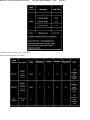
Warranty - Claims Submission
Bulletin No.: 06-00-89-054
Date: November 30, 2006
WARRANTY ADMINISTRATION
Subject:
Warranty Claims Submission - Importance of GM Part Numbers and Date Coded Parts
Models:
2007 and Prior GM Passenger Cars and Light Duty Trucks
2003-2007 HUMMER H2, H3
2005-2007 Saab 9-7X
GM Part Numbers
All parts used on GM vehicles are assigned a GM part number. Additionally, most of the parts used in the manufacturing of GM vehicles are marked
with GM part numbers directly on the part. This allows for easy verification of Genuine GM parts whether stocked at the warehouse, installed on a
vehicle, or being returned for warranty claims. Running changes are also sometimes necessary during a model year resulting in additional part number
changes mid-year.
Date Coded Parts and Identification Marks
Many of the parts used on powertrain, chassis, electrical and interior assemblies are marked and date coded in a variety of ways. You may find stickers,
bar codes, embossed clock faces, number stampings and riveted tags among many other methods on the parts you possess. While many of these
components are supplied to General Motors, almost all suppliers track these identifications as a method of quality assurance and containment if ever an
issue arises about a specific part.
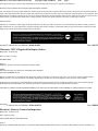
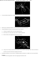
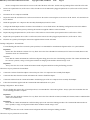
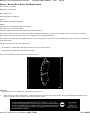
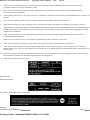
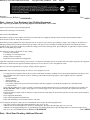
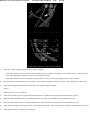
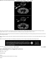
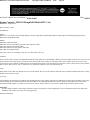
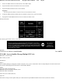
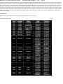
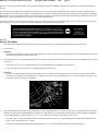
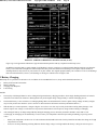
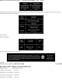
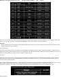
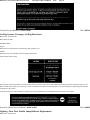
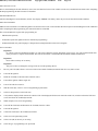
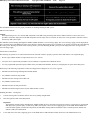
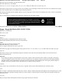
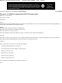
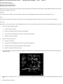
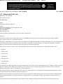
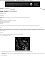
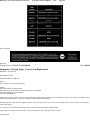
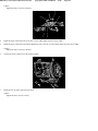
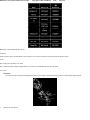
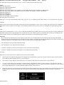
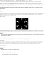
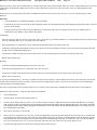
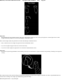
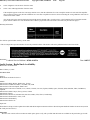
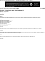
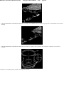
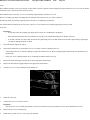
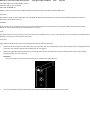
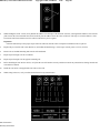
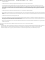
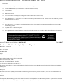
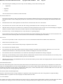
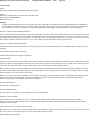
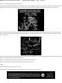
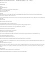
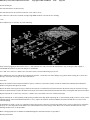
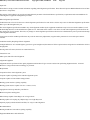
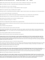
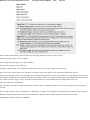
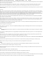
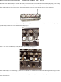
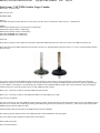
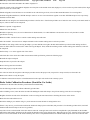
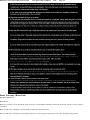
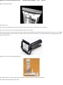
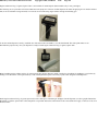
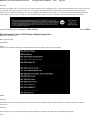
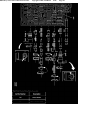
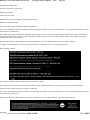
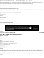
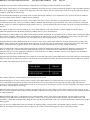
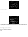
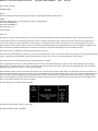
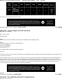
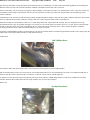
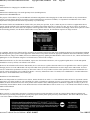
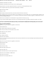
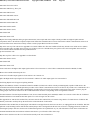
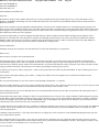
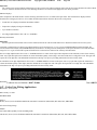
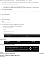
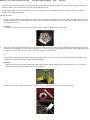
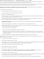
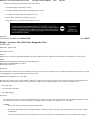
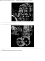
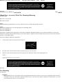
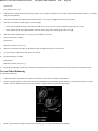
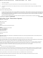
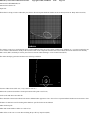
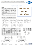
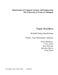
Date Code Example
The sample picture is from a 2.4L 4 cylinder front engine cover. On this part, the date code appears as a "clock" wheel.
On the first day for each month of production, the casting dye is pulled. Using a center punch, an operator manually punches another point on the date
code wheel. To decode, you simply count the number of center punches, or impression, in the dial of the clock and you have the month.
The example picture has eight impressions, or center punch marks, on the wheel. The year is cast into the center of the dial or clock face. Therefore, the
example is identified as being from August 2006. This date along with the part number, and many different identifiers cast into the parts, are used to
track variations with multiple dies or production locations. When these marks are on the exterior surfaces when installed, they give GM dealers a
powerful advantage when used for inspection purposes.
When the above information is tied to the correct VIN of the vehicle, along with a complete and detailed repair order, it becomes an effective tool to
2004 Chevy Truck Tahoe 2WD V8-5.3L VIN T
Copyright © 2009, ALLDATA
10.10
Page 2
isolate parts with a given concern. This all depends on your dealership and care you take in regards to returned parts.
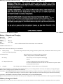
Warranty Claims Submittal and Accompanying Returned Parts Guidelines
It is vital that the exact part(s) replaced during a warranty repair be returned when requested. These parts must be the specific ones associated with the
repair order requested and must carry the proper date codes for the production run of the vehicle or component. Substitute parts are not acceptable. This
information is used during warranty part reviews and is tracked to determine possible problems with a specific production run. The more precisely that
GM can isolate a production time frame that is causing customer concerns, the quicker and more effectively we can target a solution.
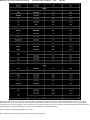
Warranty Debits
Parts that are returned out of date range for the specified vehicle on the repair order will first be cross-checked under the vehicle warranty system for
past replacements. If a past replacement is noted the warranty data will be recorded as such and the claim will be processed. Parts returned out of date
range for the vehicle repaired may be debited back to the dealer.
DisclaimerTechnical Service Bulletin # 06-00-89-050
Date: 061122
Warranty - DTC's Required On Repair Orders
Bulletin No.: 06-00-89-050
Date: November 22, 2006
INFORMATION
Subject:
Diagnostic Trouble Codes (DTCs) Required On Repair Orders
Models:
2003-2007 Passenger Cars and Trucks (Including Saturn and Saab)
2003-2007 HUMMER H2, H3
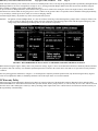
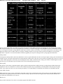
Dealers are required to record ANY and ALL diagnostic trouble codes (DTCs) on the repair order (R.O.), per the Service Policies and Procedures
Manual, Section 1.6.2. This information is needed by Engineering to facilitate the root cause diagnosis of the electronic control module.
Technicians are required to provide enough detail so that the DTC that is most likely to have caused the condition can be clearly identified by the
dealership Warranty Administrator. The warranty claim must be submitted with the DTC in the OBD II field of the claim.
FAILURE TO COMPLY WITH THIS REQUIREMENT COULD LEAD TO THE REJECTION OR DEBIT OF THE WARRANTY CLAIM.
DisclaimerTechnical Service Bulletin # 03-06-04-012A
Date: 050810
Electrical - Harness Connection Inspection
Bulletin No.: 03-06-04-012A
Date: August 10, 2005
ADVANCED SERVICE INFORMATION
Subject:
Inspection of All Related Wiring Harness Connections When Diagnosing Miscellaneous DTCs, Intermittent Driveability Concerns, Hard Start, No
2004 Chevy Truck Tahoe 2WD V8-5.3L VIN T
Copyright © 2009, ALLDATA
10.10
Page 3
Start, Incorrect Gauges, Inoperative Air Conditioning Systems, Service Engine Soon Lamps Illuminated, 4WD Lamp Illuminated, Instrument Panel
Gauges Inoperative, Cruise Inoperative
Models:
2006 and Prior Cars and Light Duty Trucks
2003-2006 HUMMER H2
2006 HUMMER H3
2005-2006 Saab 9-7X
Supercede:
This bulletin is being revised to add models, model years and additional information. Please discard Corporate Bulletin Number 03-06-04-012 (Section
06 - Engine/Propulsion System).
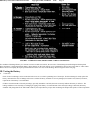
When servicing a vehicle for any type of customer concern, the following steps are imperative. Inspect and ensure the integrity of all related wiring
harness connectors. If the wiring harness connectors are not properly put together or engaged before they are locked together, numerous types of
intermittent conditions may occur, which may include any of the symptoms listed above and possibly others.
The first step in any type of electrical diagnosis is a visual and physical inspection of the wiring harness connectors for integrity. Many times, the
vehicle may be repaired just by disconnecting and reconnecting the connectors. As with all repairs to wiring harness connectors and terminals, a pull
test of the terminals within the connector should be performed. A pull test is performed by inserting the proper size terminal test tool (not a paper clip)
into the terminal to determine whether or not the terminal is making good contact, or whether the terminal has been damaged from the prior improper
connection or lack of connection.
Note:
Most terminals used in current module connectors (ECM, BCM, EBTCM and the like) are small 0.64 mm sq. terminals and can be damaged by
probing with the wrong tool.
The J 3561 6-64A or B probe has been designed for these terminals that may be both a round or square design.
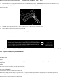
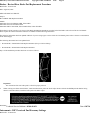
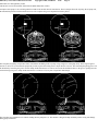
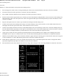
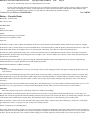
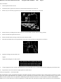
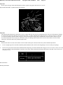
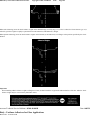
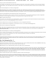
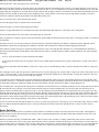
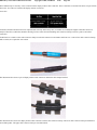
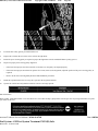
For example, if the Connector C2 of the engine wiring harness to the Powertrain Control Module (PCM), for the 2.2L equipped Cavalier or Sunfire is
not properly seated into the PCM:
^
The cam lock lever may close, however improperly.
^
The cam lock lever may even snap out of position.
^
The vehicle may have an intermittent condition with any one of the components which are controlled or monitored by the PCM.
THE CAM LOCK LEVER IS DESIGNED TO PULL (OR ASSIST) THE CONNECTOR INTO ITS FINAL POSITION ONCE IT HAS BEEN
PRESSED STRAIGHT INTO THE PCM HEADER PAST THE INITIAL DETENT, ALLOWING THE LEVER TO BE MOVED INTO THE
LOCKED POSITION. It is not only a retainer but an assist during the connection process . When the wiring harness connector is properly connected to
the PCM, a snap will be heard when the connector is in position to be fully seated. The cam lock lever may then be closed. The cam lock lever will then
do its designated job as both an assist and ensuring the connector does not come apart due to vibration or other types of conditions found in vehicles as
they travel down the highway.
Remember, if a terminal (metal) or the connector (plastic) is damaged, they should be replaced. DO NOT replace the complete wiring harness assembly.
Some harnesses are now on order restriction since most harness damage can be repaired.
Terminals and terminal removal tools are in the J 38125 Terminal Repair Kit and pigtails or complete connectors can be obtained through normal parts
ordering procedures OR from GMSPO and Saab PDC along with tape or conduit.
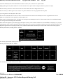
DisclaimerTechnical Service Bulletin # 06-08-45-004
Electrical - Instrument Panel & General Wiring Repair
Bulletin No.: 06-08-45-004
Date: May 02, 2006
Date: 060502
2004 Chevy Truck Tahoe 2WD V8-5.3L VIN T
Copyright © 2009, ALLDATA
10.10
Page 4
INFORMATION
Subject:
Instrument Panel (I/P), Body and General Wiring Harness Repair
Models:
2007 and Prior GM Cars and Trucks
2003-2007 HUMMER H2
2006-2007 HUMMER H3
Important:
A part restriction has been implemented on all Body and I/P harnesses and is being administered by the PQC. If a body or I/P harness replacement is
required, it can take 12-28 weeks for a harness to be built and delivered to a dealer. The dealer technician is expected to repair any harness damage
as the first and best choice before replacing a harness.
In an effort to standardize repair practices, General Motors is requiring that all wiring harnesses be repaired instead of replaced. If there is a question
concerning which connector and/or terminal you are working on, refer to the information in the appropriate Connector End Views in SI. The Instruction
Manual J 38125-620, which is sent with each new update of the J 38125 Terminal Repair Kit, also has terminal crimping and terminal remove
information.
Important:
There are some parts in the J 38125 Terminal Repair Kit (i.e. SIR connector CPAs and heat shrink tube (used in high heat area pigtail replacement)
and some TPAs that are not available from GMSPO. It is vitally important that each update to the J 38125 Terminal Repair Kit be done as soon as it
arrives at the dealer.
Utilize the Terminal Repair Kit (J 38125) to achieve an effective wiring repair. The Terminal Repair Kit has been an essential tool for all GM Dealers
since 1987. Replacement terminals and tools for this kit are available through SPX/Kent Moore. Refer to Corporate Bulletin Number 06-08-45-001 for
more information.
The Instruction Manual J 38125-620, which is sent with each new update to the J 38125 Terminal Repair Kit, also has terminal crimping and terminal
removal information.
U.S. Dealers Only - Training courses (including Tech Assists, Emerging Issues, Web, IDL and Hands-on) are available through the GM Training
website. Refer to Resources and then Training Materials for a complete list of available courses.
Canadian Dealers Only - Refer to the Training section of GM infoNet for a complete list of available courses and a copy of the J 38125 Terminal Repair
Kit Instruction Manual.
Wiring repair information is also available in Service Information (SI). The Wiring Repair section contains information for the following types of
wiring repairs:
-
Testing for intermittent conditions and poor conditions
-
Flat wire repairs
-
GMLAN wiring repairs
-
High temperature wiring repairs
-
Splicing copper wire using splice clips
-
Splicing copper wire using splice sleeves
-
Splicing twisted or shielded cable
-
Splicing inline harness diodes
2004 Chevy Truck Tahoe 2WD V8-5.3L VIN T
Copyright © 2009, ALLDATA
10.10
Page 5
DisclaimerTechnical Service Bulletin # 01-01-39-003A
Date: 030714
A/C - Catastrophic Compressor Failure Debris Removal
Bulletin No.: 01-01-39-003A
Date: July 14, 2003
INFORMATION
Subject:
J 44551 A/C Suction Screen Kit Repair Recommendations and Procedures After Catastrophic Compressor Failures
Models:
1997-2004 Passenger Cars and Light Duty Trucks
2003-2004 HUMMER H2
with Delphi HD6, HU6 and HT6 Compressors
Supercede:
This bulletin is being revised to update model years and add the HUMMER H2. Please discard Corporate Bulletin Number 01-01-39-003 (Section 01 HVAC).
GM Service Operations and Delphi Thermal Systems have worked with GM dealers over the past three years to develop the tools and procedures to
increase your success rate on repairing vehicle A/C systems that experience catastrophic compressor failures.
After a catastrophic compressor failure, it is extremely important to eliminate and/or contain the debris that causes repeat repairs. The debris generated
from a catastrophic compressor failure is discharged into the compressor suction line, the discharge line, the condenser and the liquid line. The use of
the J 44551 Suction Screen Kit DOES NOT replace the need for liquid line filters as described in the vehicle specific Service Manual. Liquid line filters
should be used whenever possible (after a catastrophic compressor failure) to protect the expansion device (orifice tube or TXV) from debris.
Analysis of failed replacement compressors show the debris discharged into the INLET side of the compressor (suction line) is often pulled into the
replacement compressor. It is important to keep this debris out of the new compressor to avoid repeat compressor failure. The J 44551 Suction Screen
Kit is designed to help protect the NEW (replacement) compressor from ingesting debris that was sent into the SUCTION side of the system during a
compressor failure.
The J 44551 kit supplies your dealership with the right tools and supplies to cover the Delphi HD6, HU6 and HT6 compressors for most GM
applications. Delphi V5 and V7 compressors already have this screen installed in the suction port of the compressor and do not need an additional
screen installed.
Service Procedure
Tools Required
J 44551 Suction Screen Kit
The J 44551 Suction Screen Kit contains three different screen sizes. It is important to select the correct size screen that will press fit into the suction
port of the compressor hose assembly. The screen should not be installed loose inside the hose assembly.
Installation Procedure
1.
Evacuate the air conditioning system completely using the applicable recovery equipment.
2.
Remove the bolt that attaches the manifold of the muffler assembly hose to the air conditioning compressor.
2004 Chevy Truck Tahoe 2WD V8-5.3L VIN T
Copyright © 2009, ALLDATA
10.10
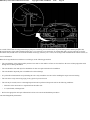
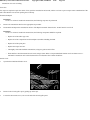
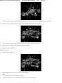
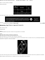
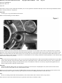
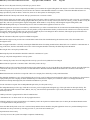
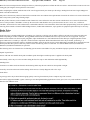
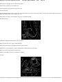
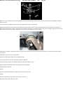
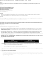
3.
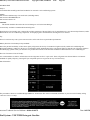
Use the Suction Port Sizing Tool (1) in order to determine the appropriate size filter screen.
4.
Install the proper Installation Mandrel (1) on the threaded portion of the Installation Tool.
5.
Using the Installation Tool, place the manifold into the fixture of the tool.
Page 6
5.1.
Lubricate the applicable filter screen with refrigerant lubricant.
5.2.
Ensure that you are on the suction side of the air conditioning manifold.
5.3.
Place the filter screen straight into the bore before proceeding.
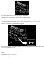
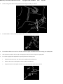
5.4
Using a 9/16 in wrench, turn the bolt of the Installation Tool (3) clockwise, pressing the filter screen (2) into the bore.
The filter screen must be flush with or slightly below the bore.
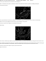
6.
Reinstall the manifold (1) on the rear of the air conditioning compressor. Make sure to tighten to the correct specifications.
Important:
Be sure to clean the appropriate surface before applying the Notification Label.
2004 Chevy Truck Tahoe 2WD V8-5.3L VIN T
7.
Copyright © 2009, ALLDATA
10.10
Page 7
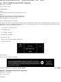
Included in the kit is a bright yellow Notification Label with the following message: ATTENTION! Suction Line Screen Installed. It is very
important that you apply this label to the manifold, the suction line, or some other appropriate, highly visible location.
Removal Procedure
1.
Using the appropriate Removal Tool (1), place the Removal Tool (1) into the bore of the filter screen.
2.
Turn the Removal Tool one turn clockwise, or until tight.
3.
Turn the nut clockwise to remove the filter screen using the appropriate size wrench.
^
11/16 in wrench for size A filter screen
^
3/4 in wrench for size B filter screen
^
7/8 in wrench for size C filter screen
DisclaimerTechnical Service Bulletin # 03-01-39-008
Date: 030625
A/C - System Changes/Synchronization
Bulletin No.: 03-01-39-008
Date: June 25, 2003
INFORMATION
Subject:
Changes in A/C Compressor On/Off Instrument Panel Display Symbol from 2003 to 2004 Model Year and Synchronizing the Driver and Passenger Set
Temperatures
Models:
2003-2004 Cadillac Escalade, Escalade ESV, Escalade EXT
2003-2004 Chevrolet Avalanche, Silverado, Suburban, Tahoe
2003-2004 GMC Denali, Denali XL, Sierra, Sierra Denali, Yukon, Yukon XL
2003-2004 HUMMER H2
with Dual Zone Automatic Climate Control (RPO CJ2)
This bulletin is being issued to clarify the operation of the A/C compressor and to explain the driver and passenger set temperature operation on
vehicles equipped with dual zone automatic climate control systems (RPO CJ2).
Operation of A/C Compressor 2003 A/C OFF Indicator
2004 Chevy Truck Tahoe 2WD V8-5.3L VIN T
Copyright © 2009, ALLDATA
10.10
Page 8
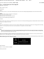
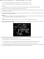
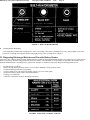
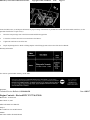
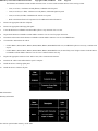
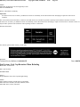
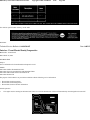
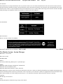
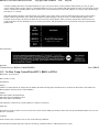
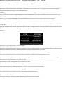
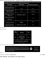
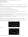
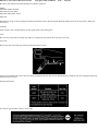
On 2003 model year vehicles, a snowflake with a slash through it is shown on the display when the A/C has been turned off (by a press of the A/C
button). The A/C can be turned on by pressing the AUTO button or pressing the A/C button again. This will remove the indicator from the display.
Some customers may comment about poor A/C performance after they've pressed the A/C button and see what appears to be the snowflake illuminated
on the display. What has actually happened, though, is that they have disabled the operation of the A/C compressor and the snowflake symbol, upon
closer inspection, has a slash through it.
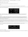
2004 A/C ON Indicator
On 2004 model year vehicles, the indicator will change to a snowflake (without the slash) and it will be illuminated whenever the A/C compressor
operation is enabled.
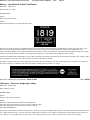
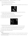
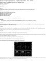
Driver and Passenger Set Temperature Operation
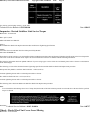
The display of driver and passenger set temperature may also cause confusion. It is possible to set the left temperature control to full cold and the right
temperature control to full hot with little indication on the display that the two temperatures are set differently.
If the driver set temperature is set to 16°C (60°F) and the passenger set temperature is set to 32°C (90°F), the display will show the passenger set
temperature for only five seconds. After that time, the display will show only the driver set temperature and a small arrow pointing left. The arrow is
very important because it is the only indicator that the left and right temperatures are not equal. When both the driver and passenger set temperatures are
equal, the display will have arrows pointing both left and right.
With different set temperatures, it is possible to have the left temperature door flowing air through the evaporator and the right temperature door
flowing air through the heater core. This may cause the overall passenger compartment temperature to not be cooled or heated as well as the customer
might expect.
In order to synchronize the driver and passenger temperatures, follow these steps:
^
Set the driver and passenger set temperatures to the desired temperatures, OR
^
Push and hold the AUTO button for at least four seconds to make both driver and passenger set temperatures set to the driver's set temperature. Both
set temperatures can be controlled by the left temperature control knob when the zones are linked in this manner. Turning the passenger set
temperature knob will "unlink" the zones again.
DisclaimerTechnical Service Bulletin # 04-01-38-008
A/C - Defaults To Defrost Mode/Poor Control
Bulletin No.: 04-01-38-008
Date: 040617
2004 Chevy Truck Tahoe 2WD V8-5.3L VIN T
Copyright © 2009, ALLDATA
10.10
Page 9
Date: June 17, 2004
TECHNICAL
Subject:
HVAC System Cannot be Controlled or Defaults to Defrost Mode (Repair HVAC Actuator Harness)
Models:
2003-2005 Cadillac Escalade, Escalade ESV, Escalade EXT
2003-2005 Chevrolet Avalanche, Silverado, Suburban, Tahoe
2003-2005 GMC Sierra, Yukon, Yukon XL
Condition
^
Some customers may comment that they cannot control the HVAC (heating, ventilation and air conditioning) system. Others may comment that the
HVAC system defaults to the Defrost mode.
^
Technicians may find that the following diagnostic trouble codes have set:
^
B0229 Recirculation Actuator
^
B0414 Left Air Temperature Actuator
^
B0424 Right Air Temperature Actuator
^
B3770 Mode Actuator Cause
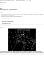
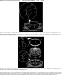
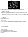
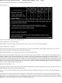
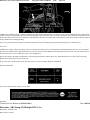
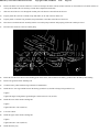
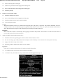
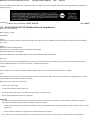
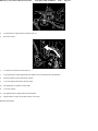
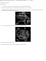
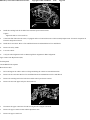
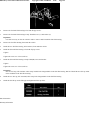
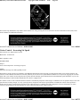
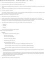
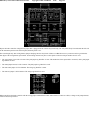
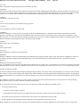
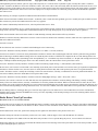
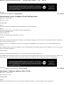
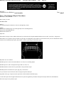
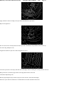
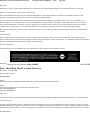
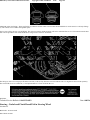
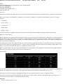
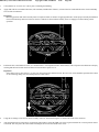
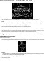
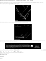
The HVAC actuator harness may contact a sharp edge on the instrument panel support brace, causing a rub through condition and a ground out of the
actuator control and/or feedback circuits.
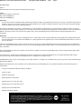
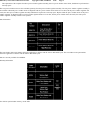
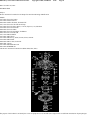
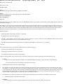
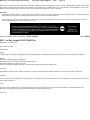
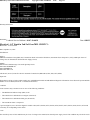
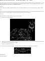
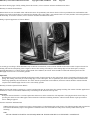
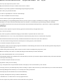
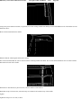
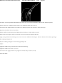
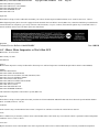
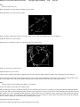
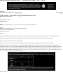
Correction
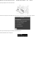
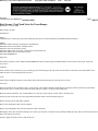
Locate the HVAC actuator harness contact point shown by the arrow in the above illustration. The illustration is of the instrument panel with the
instrument panel compartment door opened and folded downward. The actuator harness is located in the left side of the opening in the instrument panel.
Technicians are to inspect the HVAC actuator harness for contact with the instrument panel support brace. Repair any damage to the actuator harness
wiring and install protective plastic conduit over the harness. Install friction tape over the sharp edge of the instrument panel brace. Clear the diagnostic
2004 Chevy Truck Tahoe 2WD V8-5.3L VIN T
Copyright © 2009, ALLDATA
10.10
Page 10
trouble codes and verify proper HVAC system operation.
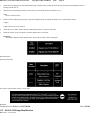
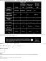
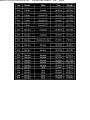
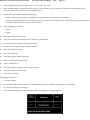
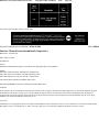
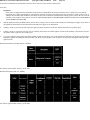
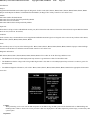
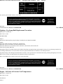
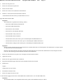
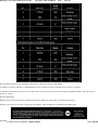
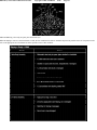
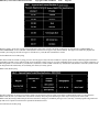
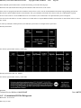
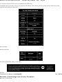
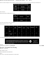
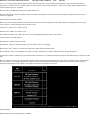
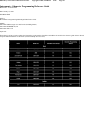
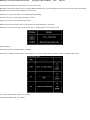
Warranty Information
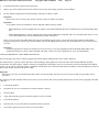
For vehicles repaired under warranty, use the table.
Disclaimer
Technical Service Bulletin # 01-01-38-006D
Date: 040901
A/C - R-134a System Flushing Procedures
File In Section: 01 - HVAC
Bulletin No.: 01-01-38-006D
Date: September, 2004
INFORMATION
Subject:
Contaminated R-134a A/C Systems - Air Conditioning System Flushing Procedures and Universal In-Line A/C Filter Installation
Models:
1993-2005 Passenger Cars and Light Duty Trucks
with Air Conditioning
This bulletin is being revised to update the parts information. Please discard Corporate Bulletin Number 01-01-38-006C (Section 01 - HVAC).
GM Service Operations has worked with GM dealers to develop tools and procedures to properly flush A/C (air conditioning) systems. The
recommended flushing procedure uses liquid R-134a refrigerant to perform the system flush and is the only GM approved method for system flushing.
The use of alternate methods that utilize solvents has proven to be detrimental to A/C system performance and durability. Every General Motors dealer
has received a J 43600 ACR 2000 Air Conditioning Service Center that has built-in A/C system flushing capabilities. Every General Motors dealer has
also received a J 45268 Flush Adapter Kit to utilize the flushing capability of the J 43600 ACR 2000.
This bulletin contains a general outline of the procedure and when to perform A/C system flushing. Vehicle specific flushing information is contained
in the HVAC section of SI.
A/C system flushing should NOT be routinely performed when a system failure is encountered. System flushing takes a considerable amount of time to
perform and is NOT necessary on most system failures. System flushing requires prior authorization by the GM Area Service Manager (the District
Service Manager in Canada) and should be performed only when one of the following conditions is found:
^
A desiccant bag failure.
^
A gross overcharge of A/C system lubricant.
2004 Chevy Truck Tahoe 2WD V8-5.3L VIN T
Copyright © 2009, ALLDATA
^
The A/C system lubricant is contaminated.
^
A catastrophic compressor failure causing oil contamination.
10.10
Page 11
A/C system flushing will remove some of the metal particles during a flush, but flushing is not completely effective in removing all metallic debris.
System flushing should not be considered if removal of metallic debris is the only objective. GM Service Operations continues to strongly recommend
the use of a Liquid Line Filter and a Suction Screen to control this type of system contamination and avoid repeat failures.
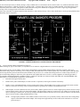
A/C System Flushing Procedure
Tools Required
^
J 43600 ACR 2000 Air Conditioning Service Center
^
J 45268 A/C Flush Adapter Kit J 41447 R-134a Tracer Dye or equivalent
^
J 41459 A/C Tracer Dye Injector or equivalent
^
J 42220 Universal 12V Leak Detection Lamp or equivalent
^
J 39400 Halogen Leak Detector or equivalent
^
J 44551 A/C Suction Screen Kit
^
J 45037 Oil Injector kit
^
J 45037-46 GM Universal Compressor PAG Oil (packaged as 6, 8 oz tubes)
A warm engine compartment or higher ambient temperatures as well as air flow across the heat exchangers (evaporator, accumulator and condenser)
speed the refrigerant recovery time during the A/C flush procedure. Whenever possible, warm the engine prior to A/C system flushing. An external fan
blowing across the condenser and running the A/C blower motor while the engine is running may be used to speed up refrigerant recovery.
Front Only A/C Systems
1.
Recover the refrigerant from the vehicle.
2.
Remove the expansion device (orifice tube or TXV (Thermostatic Expansion Valve)).
3.
Connect the A/C lines with the orifice tube removed or install the appropriate TXV Adapter from the J 45268 A/C Flush Adapter Kit.
4.
Disconnect the A/C compressor manifold (never flush through a compressor).
5.
Inspect the end of the suction hose for a suction screen. Remove the suction screen using the screen remover in the J 44551 A/C Suction Screen
Kit, if installed.
6.
Install the appropriate A/C compressor hose assembly flush adapter(s) from kit J 45268.
7.
Configure the flush adapter and hose for either a forward flush or reverse flush. Refer to the Flushing Configuration section of this bulletin.
Front/Rear (Dual Circuit) A/C Systems
Each circuit of a front/rear A/C system must be flushed separately. Flow to one circuit must be blocked with the use of a blocked orifice tube or
blocked TXV. The front circuit should always be flushed first.
Front Circuit
1.
Recover the refrigerant from the vehicle.
2.
Remove the expansion device (orifice tube or TXV) from the front circuit.
3.
Re-connect the A/C lines with the orifice tube removed or install the appropriate non-blocked (open) TXV Adapter from kit J 45268.
Important:
A blocked orifice tube is not supplied with the J 45268 Adapter kit. A blocked orifice can be made as follows: Cut the orifice tube frame and
screen.
2004 Chevy Truck Tahoe 2WD V8-5.3L VIN T
Copyright © 2009, ALLDATA
10.10
Page 12
Remove enough of the frame and screen to access the end of the brass orifice tube. Seal the tube by pinching off the end of the orifice tube.
4.
Remove the expansion device (orifice tube or TXV) from the rear circuit and install a plugged expansion device (orifice tube or TXV) into the
rear circuit.
5.
Disconnect the A/C compressor manifold.
6.
Inspect the end of the suction hose for a suction screen. Remove the suction screen using the screen remover in the J 44551 A/C Suction Screen
Kit, if installed.
7.
Install the appropriate A/C compressor hose assembly flush adapter(s) from kit J 45268.
8.
Configure the flush adapter and hose for either a forward flush or a reverse flush. Refer to the Flushing Configuration section of this bulletin.
9.
Perform the flush of the front system by following the instructions supplied with the J 43600 ACR 2000.
10.
Replace the plugged expansion device (orifice tube or TXV) in the rear circuit with an open expansion device (orifice tube or TXV).
11.
Replace the open expansion device (TXV or orifice tube) in the front circuit with a plugged expansion device (orifice tube or TXV).
12.
Flush the rear system by following the instructions supplied with the J 43600 ACR 2000.
Flushing Configuration - Forward Flush
Forward flushing (the same flow as normal system operation) is recommended for contaminated refrigerant and/or A/C system lubricant.
Important:
Install a new filter inside the J 45268-1 for every flush. Service the filter with GM P/N 5651802 (use P/N 729832 in Canada). Remove and
discard the check valve from the filter.
Important:
Check that the J 43600 ACR 2000 has a sufficient refrigerant charge prior to the start of the flushing procedure. The J 43600 ACR 2000 must
have at least 7 pounds (3.18 kgs) of refrigerant available for charging in the machine's internal storage vessel.
Important:
Always close the valve on the J 43600 ACR 2000 external refrigerant tank before starting the flushing procedure.
Follow these steps to perform the forward flush:
1.
Connect the J 45268-1 flush filter adapter to the suction port of the A/C compressor hose assembly flush adapter.
2.
Connect the blue hose from the J 43600 ACR 2000 to the J 45268-1 flush filter adapter.
3.
Connect the red hose from the J 43600 ACR 2000 to the discharge port of the A/C compressor hose assembly flush adapter.
4.
Follow the instructions supplied with the J 43600 ACR 2000 and flush the A/C system.
Flushing Configuration - Reverse Flush
Reverse flushing (the opposite flow of normal operation) is recommended for a desiccant bag failure. Always replace the accumulator after the
reverse flushing procedure is complete.
Important:
Install a new filter inside the J 45268-1 for every flush. Service the filter with P/N 5651802 (in Canada, P/N 729832). Remove and discard the
check valve from the filter.
Important:
Check that the J 43600 ACR 2000 has a sufficient charge prior to the start of the flushing procedure. The J 43600 ACR 2000 must have at
least 7 pounds (3.18 kgs) of refrigerant available in the machine's internal storage vessel.
Important:
Always close the valve on the J 43600 external refrigerant tank before starting the flushing procedure.
Follow these steps to perform the reverse flush:
2004 Chevy Truck Tahoe 2WD V8-5.3L VIN T
Copyright © 2009, ALLDATA
10.10
Page 13
1.
Connect the J 45268-1 flush filter adapter to the discharge port of the A/C compressor hose assembly flush adapter.
2.
Connect the blue hose from the J 45268-1 flush filter adapter.
3.
Connect the red hose to the suction port of the A/C compressor hose assembly flush adapter.
4.
Follow the instructions supplied with the J 43600 ACR 2000 and flush the A/C system.
After Flushing Is Complete
Important:
Flushing will remove all the A/C system lubricant and leak detection dye from the A/C system. After a catastrophic compressor failure, it is
extremely important to eliminate and/or contain the debris that may cause repeat repairs. The debris generated from a catastrophic compressor
failure will be discharged into the compressor suction line, discharge line, condenser and liquid line. The use of the J 44551 Suction Screen
kit DOES NOT replace the need for liquid line filters as described in the vehicle specific Service Information. A liquid line filter should be
installed whenever possible, after a catastrophic compressor failure, to protect the expansion device (orifice tube or TXV) in both the front
and rear systems from debris.
The J 44551 supplies your dealership with the right tools and supplies to cover the Delphi HD6, HU6 and HT6 compressors, as well as most
non-Delphi compressors, for most GM applications. Delphi V5 and V7 compressors already have this screen installed in the suction port of the
compressor and do not need an additional screen installed.
The J 44551 Suction Screen Kit contains three different screen sizes. Additional screen sizes are being developed. It is important to select the
correct size screen that will press fit into the suction port of the compressor hose assembly. The screen should not be installed loose inside the
hose assembly.
1.
Insert the J 44551-6 sizing tool into the suction hose to select the correct size suction screen.
2.
Insert the suction screen into the compressor end of the suction hose.
3.
Select and install the correct mandrel to the J 44551-5.
4.
Install the J 44551-5 screen installation tool over the end of the suction hose and the suction screen.
Important:
Correct placement of the J 44551 is critical.
5.
Tighten the forcing screw of the J 44551-5. The suction screen is fully installed when the screen is flush with the end of the suction hose fitting.
6.
Remove the J 44551-5 suction screen tool from the suction hose.
7.
Install the J 44551-1 Suction Screen Notification Label.
8.
Remove the A/C compressor.
9.
Remove the A/C compressor drain plug, if equipped. Drain the A/C system lubricant from the compressor into a clean, graduated cylinder. Rotate
the compressor input shaft to assist in draining the A/C system lubricant from the compressor. Measure and record the amount of A/C system
lubricant removed.
10.
Install the A/C compressor drain plug, if equipped.
11.
Install the A/C compressor.
12.
Remove the blocked orifice tube or TXV adapter (front/rear systems only).
13.
Install a new orifice tube or remove the TXV adapter.
^
Inspect the original TXV for debris.
^
Clean or replace the original TXV as needed.
^
For front/rear systems, be sure both expansion devices (orifice tubes or TXVs) are installed.
Important:
2004 Chevy Truck Tahoe 2WD V8-5.3L VIN T
Copyright © 2009, ALLDATA
10.10
Page 14
Even after a system flush, control devices are subject to contamination and malfunction. To insure long term reliability the installation of the
newly redesigned in-line A/C filter before an orifice tube or rear TXV is recommended.
^
Install the in-line filter on front A/C systems before the orifice tube.
^
Install the in-line filter on front/rear A/C systems before the "Y" in the evaporator tube.
^
Do not allow metal burrs to enter the evaporator tube during cutting or when removing the burrs.
^
Because of limited space in the engine compartment, it may be necessary to remove the system's existing orifice tube and install the orifice
in the in-line filter.
14.
Install a Universal In-line A/C Filter, P/N 89016656 (AC Delco P/N 15-10413). Refer to the instruction sheet included with the filter for detailed
installation instructions. Re-install the suction screen if it was previously removed.
15.
Look up the required amount of A/C system lubricant for the vehicle being worked on. Refer to the System Capacities table in the appropriate
section of SI. Remember that after a system flush there is no lubricant in the A/C system.
16.
Install the proper amount of Synthetic Lubricant (Universal Refrigerant Oil), P/N 12378526 (in Canada, P/N 88900060), into the A/C system
using the J 45037 Oil Injector.
17.
Add one bottle of J 41447 R-134a Tracer Dye, GM P/N 12346303 (in Canada, P/N 10953458), or the equivalent, using the J 41459 dye injector
(or the equivalent).
18.
Evacuate the A/C system.
19.
Recharge the A/C system to the proper charge level specified for that vehicle's A/C system.
20.
Verify proper A/C system operation.
21.
Leak test all connections using the J 44220 Universal 12V Leak Detection Lamp, the J 39400-A Leak Detector or equivalents. Remember that the
A/C system must operate for several minutes before leak dye will show a leak if one is present.
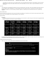
Parts Information
Warranty Information
GM has not established a specific labor operation for system flushing. When system flushing is necessary during the warranty period, submit additional
labor hours with the labor operation used for the system repair.
2004 Chevy Truck Tahoe 2WD V8-5.3L VIN T
Copyright © 2009, ALLDATA
10.10
Page 15
DisclaimerTechnical Service Bulletin # 03-08-44-018C
Date: 060109
A/C/Audio System - Rear A/C, Audio Inoperative
Bulletin No.: 03-08-44-018C
Date: January 09, 2006
TECHNICAL
Subject:
Rear Seat Audio (RSA) and/or Rear HVAC Inoperative (Replace RSA Module)
Models:
2003-2006 Cadillac Escalade, Escalade ESV, Escalade EXT
2003-2006 Chevrolet Avalanche, Silverado Crew Cab, Suburban, Tahoe
2003-2006 GMC Sierra Crew Cab, Sierra Denali, Yukon, Yukon XL, Yukon Denali, Yukon Denali XL
2003-2006 HUMMER H2
with Rear Seat Radio Control (RPO UK6)
Supercede:
This bulletin is being revised to add 2006 model year vehicles. Please discard Advanced SI Resolution Bulletin Number 03-08-44-018B (Section 08 Body and Accessories).
Condition
Some customers may comment that the Rear Seat Audio (RSA) or the rear HVAC controls are inoperative. The display will be blank and there is no
communication to the RSA/HVAC module.
Cause
A microcontroller was found to lock up causing an "ALDL No ALDL" communication condition. This required the cycling of power by
disconnecting/reconnecting the RSA module.
Correction
Replace the RSA module to correct this condition. The RSA module has been updated to eliminate the "HVAC No ALDL" communication concern.
Parts Information
Warranty Information
2004 Chevy Truck Tahoe 2WD V8-5.3L VIN T
Copyright © 2009, ALLDATA
10.10
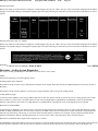
Page 16
For vehicles repaired under warranty, use the table.
Disclaimer
Technical Service Bulletin # 02-06-04-015A
Date: 060307
Starting System - Engine No Start/No Crank Condition
Bulletin No.: 02-06-04-015A
Date: March 07, 2006
TECHNICAL
Subject:
Intermittent No Crank, No Start (Clean Battery Side Terminal Stripped Threads, Replace Battery Cable Bolt)
Models:
2001-2007 GM Passenger Cars and Light-Duty Trucks (Including Saturn)
2003-2007 HUMMER H2
2006-2007 HUMMER H3
2005-2007 Saab 9-7X
with Side-Mounted Battery Terminals
Supercede:
This bulletin is being revised to update the models and provide a new labor operation number for this repair. Please discard Corporate Bulletin Numbers
02-06-04-015 and 03-06-03-006A (Section 06 - Engine/Propulsion System).
Condition
Some customers may comment on an intermittent no crank, no start condition.
Cause
This condition may be due to poor battery cable connections. Cross-threaded/stripped battery cable bolts inside the battery side post terminals may
cause poor battery cable connections.
Correction
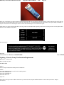
To avoid replacing the battery , do the following steps:
^
Clean the threads in the battery side post terminals using a 3/8" (# 16) NC bottom tap.
^
Replace the battery cable bolt.
The battery cable bolt is serviced separately from the cable and is available from your Parts Department. Be sure to use the correct bolt.
2004 Chevy Truck Tahoe 2WD V8-5.3L VIN T
Copyright © 2009, ALLDATA
10.10
Page 17
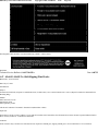
Warranty Information
For vehicles repaired under warranty, use the table.
Warranty Information (Saab U.S. Models)
For vehicles repaired under warranty, use the table.
Disclaimer
Technical Service Bulletin # NHTSA04V045000
Date: 040201
Recall 04V045000: Possible Hydro-Boost Defect
DEFECT: Certain sport utility vehicles, pickup trucks, and passenger vans fail to comply with the requirements of Federal Motor Vehicle Safety
Standard No. 135, "Passenger Car Brake Systems." Some of these vehicles were produced with an out-of-specification brake hydro-boost housing relief
valve bore. Consequently, the valve O-ring seal may fracture. Steering efforts may be slightly increased while braking or parking. Under certain driving
conditions, a fractured seal may also require an increase in the applied brake pedal effort to achieve the same vehicle deceleration.
REMEDY: Dealers are to replace the hydro-boost relief valve. The manufacturer has reported that owner notification is expected to begin during the
second quarter of 2004. Owners may contact Cadillac at 1-866-982-2339; Chevrolet at 1-800-630-2438; GMC at 1-866-996-9463; or Hummer at
1-866-486-6376. Technical Service Bulletin # 04-05-23-006
Date: 040801
2004 Chevy Truck Tahoe 2WD V8-5.3L VIN T
Copyright © 2009, ALLDATA
10.10
Page 18
Brakes - Revised Rear Brake Pad Replacement
File In Section: 05 - Brakes
Bulletin No.: 04-05-23-006
Date: August, 2004
SERVICE MANUAL UPDATE
Subject:
Revised Brake Pads Replacement-Rear
Models:
2000-2004 Chevrolet Suburban-2WD, Tahoe-2WD
2002-2004 Chevrolet Avalanche-2WD
2000-2004 GMC Yukon-2WD, Yukon Denali-2WD, Yukon XL-2WD
This bulletin is being issued to revise Step 2 of the Brake Pads Replacement-Rear procedure in the Disc Brakes sub-section of the Service Manual.
Please replace the current information in the Service Manual with the following information.
The following information has been updated within SI. If you are using a paper version of this Service Manual, please make a reference to this bulletin
on the affected page.
The following documents have been updated in SI:
^
Document ID # 710680-Brake Pads Replacement-Rear (Except 15 Series Pickup)
^
Document ID # 745244-Brake Pads Replacement-Rear
Step 2 of the Installation procedure has been revised to as follows:
Important:
The orientation of the rear brake pads is critical for proper pad wear.
2.
When working on a 2WD 1500 UTILITY, install the inboard rear pad to the brake caliper bracket with the LONGER pad end chamfer facing
down. For all other utilities, install the brake pads to the brake caliper.
DisclaimerTechnical Service Bulletin # 04-05-23-006
Date: 040802
2004 Chevy Truck Tahoe 2WD V8-5.3L VIN T
Copyright © 2009, ALLDATA
10.10
Page 19
Brakes - Revised Rear Brake Pad Replacement Procedure
Bulletin No.: 04-05-23-006
Date: August 02, 2004
SERVICE MANUAL UPDATE
Subject:
Revised Brake Pads Replacement-Rear
Models:
2000-2004 Chevrolet Suburban-2WD, Tahoe-2WD
2002-2004 Chevrolet Avalanche-2WD
2000-2004 GMC Yukon-2WD, Yukon Denali-2WD, Yukon XL-2WD
This bulletin is being issued to revise Step 2 of the Brake Pads Replacement-Rear procedure in the Disc Brakes sub-section of the Service Manual.
Please replace the current information in the Service Manual with the following information.
The following information has been updated within SI. If you are using a paper version of this Service Manual, please make a reference to this bulletin
on the affected page.
The following documents have been updated in SI:
^
Document ID # 710680-Brake Pads Replacement-Rear (Except 15 Series Pickup)
^
Document ID # 745244-Brake Pads Replacement-Rear
Step 2 of the Installation procedure has been revised to as follows:
Important:
The orientation of the rear brake pads is critical for proper pad wear.
2.
When working on a 2WD 1500 UTILITY, install the inboard rear pad to the brake caliper bracket with the LONGER pad end chamfer facing
down. For all other utilities, install the brake pads to the brake caliper.
DisclaimerTechnical Service Bulletin # 03-00-89-021
Instruments - DIC Perceived Fuel Economy Settings
Bulletin No.: 03-00-89-021
Date: 030730
2004 Chevy Truck Tahoe 2WD V8-5.3L VIN T
Copyright © 2009, ALLDATA
10.10
Page 20
Date: July 30, 2003
INFORMATION
Subject:
New Vehicle Pre-Delivery Inspection - Perceived Fuel Economy and Driver Information Center (DIC) Settings
Models:
2003-2004 Passenger Cars and Trucks
2003-2004 HUMMER H2
with Driver Information Center (DIC)
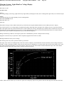
The customer's initial perception of vehicle fuel economy, based upon the information displayed on the Driver Information Center (DIC), may
contribute to poor ratings for fuel economy in various automotive surveys. The way the vehicle is handled during the build and shipping process may
leave inaccurate values in the history of the DIC.
During the pre-delivery inspection, the dealership must reset the "average fuel economy" setting.
Reset the average fuel economy setting according to the information in the appropriate Owner's Manual. Once reset, the average fuel economy will then
be calculated starting from that point.
The data used to determine fuel range is an average of recent driving conditions. This setting cannot be reset. However, as the customer's driving
conditions change, the data will be gradually updated to reflect more accurate readings.
If a customer inquires about fuel economy, and the fuel consumption information is not on the price sticker, do not exaggerate the vehicle's capabilities.
In either case, stress that fuel economy performance is highly dependent upon driving habits and vehicle usage.
DisclaimerTechnical Service Bulletin # 01-01-38-013A
Date: 031029
A/C - Unnecessary Compressor Replacement
Bulletin No.: 01-01-38-013A
Date: October 29, 2003
INFORMATION
Subject:
Diagnostic Information To Consider Before Air Conditioning Compressor Replacement
Models:
1993-2004 Passenger Cars and Light Duty Trucks
Supercede:
This bulletin is being revised to add the 2004 model year and add information for clarification. Please discard Corporate Bulletin Number 01-01-38-013
(Section 01 - HVAC).
A recently completed analysis of air conditioning (A/C) compressors that had been replaced for noise, vibration and insufficient cooling concerns has
indicated a high number of "no trouble found" results. Further studies have shown that the root cause of the customer concerns that might lead to a
compressor replacement was often a state of refrigerant charge issue or in another area or system of the vehicle. The A/C system refrigerant charge
level, either high or low, has been found to be a major contributor to unnecessary compressor replacement. The ability of the ACR 2000 Refrigerant
Recycling/Recharging Tool to recover and measure the weight of the A/C system refrigerant charge will help the technician make a more accurate
diagnosis of a charge level concern prior to any component replacement.
A thorough visual inspection should always be performed before any tests or repairs are done. Doing so may find an obvious problem that will save
time and eliminate the need for extensive diagnosis. Some additional items, as listed below, should be considered before a compressor is replaced for
2004 Chevy Truck Tahoe 2WD V8-5.3L VIN T
Copyright © 2009, ALLDATA
10.10
Page 21
noise, vibration or insufficient cooling concerns.
^
The compressor mounting bolts, brackets or braces may be loose or missing.
^
The compressor drive belt may be frayed, loose or misaligned.
^
The A/C refrigerant lines may be grounding out on body, chassis or engine components. This may allow noise and vibration to be transmitted into
the passenger compartment.
^
The air flow through the condenser may be insufficient.
-
The condenser fins may be bent or filled with debris.
-
The space between the condenser and radiator may be filled with leaves or debris.
-
The cooling fans may be inoperative or not performing as designed.
-
The installation of aftermarket accessories may alter or restrict the air flow through the condenser.
^
Inspect for missing or mispositioned air deflectors, baffles, seals and shrouds.
^
The compressor cycling switch may not be operating correctly. This may allow the evaporator core to freeze up or the compressor may not stay
engaged long enough for proper system pressures to develop.
^
The air flow through the evaporator core may be restricted.
-
The cabin filter may be plugged.
-
The evaporator core may be covered with debris.
-
The cowl air inlet leaf screen may by plugged.
^
The A/C system may be overcharged or undercharged with refrigerant. The A/C system charge weight can be measured with the ACR 2000 after a
refrigerant recovery is done.
^
The A/C system may have an improper amount or incorrect type of refrigerant oil. Only GM approved refrigerant oils should be used.
^
An A/C system sealer is not approved for use in GM vehicles.
^
The vehicle's refrigerant may be contaminated or contain an excessive amount of air. The vehicle's A/C system may have been charged with an
unapproved refrigerant. The refrigerant identifier on the ACR 2000 should alert the technician to these conditions.
^
The orifice tube or thermostatic expansion valve (TXV) may be restricted, plugged or inoperative.
^
The capillary bulb on the TXV must be properly positioned so that the valve will provide proper refrigerant flow.
^
The desiccant bag in the accumulator may have failed, allowing debris to circulate in the A/C system.
^
The A/C system charge weight may have been changed. Components with an updated design may have been released. A check for service bulletins
applicable to the vehicle being worked on should always be done.
^
A check for diagnostic trouble codes in all the control modules on the vehicle should be done. Some trouble codes will disable compressor
operation after they have set. They must be repaired and cleared before compressor operation is allowed.
^
Verify that the engine is not operating with a low unstable idle, and that the engine is operating within the compressor engagement parameters (for
example; the engine may be overheating or it may be too cold for compressor engagement).
^
The diagnostic procedures in the HVAC section of the Service Manual should be performed as written to prevent the misdiagnosis of a customer
concern. The HVAC Diagnostic System Check and the A/C System Performance Test are written for a specific model only. They are not generic
charts. They follow a logical order with detailed instructions on how to perform each step.
^
The Technical Assistance Center may be contacted for additional help and the latest information on any unusual concerns.
When a thorough HVAC system diagnosis indicates that the compressor should be replaced, follow the procedure in the appropriate Service Manual.
The oil balance instructions are an important part of the replacement procedure. The correct refrigerant oil, as listed in the Service Manual, must be used
in the new compressor. It is recommended that a suction screen filter be installed on Delphi Harrison compressors that do not already have one. The
2004 Chevy Truck Tahoe 2WD V8-5.3L VIN T
Copyright © 2009, ALLDATA
10.10
Page 22
suction screen filter is not approved for use on compressors from other manufacturers. Refer to Corporate Bulletin Number 01-01-39-003A for more
information on A/C suction screen kit repair recommendations and procedures. If the compressor has had a catastrophic internal failure, an inline filter
may be required to capture the large amount of debris that may be found to be circulating in the A/C system. In addition, the A/C system may require
flushing. Refer to Corporate Bulletin Number 01-01-38-006B for more information on flushing procedures and recommendations.
The addition of fluorescent refrigerant leak dye to the A/C system is recommended if the vehicle does not have it installed already. Some vehicles have
leak dye installed at the assembly plant and this will be indicated on the A/C charge label. Refer to Corporate Bulletin Number 00-01-38-009B for more
information. If leak dye has been added during a previous repair and has been in the vehicle for more than three years, it is recommended that additional
dye be added. Finally, a leak check of the entire A/C system should be performed before the vehicle is returned to the customer.
Important:
For all GM paid repairs, the charge summary printout from the ACR 2000 is still required to be attached to the shop copy of the repair order. The
warranty code must be submitted in the warranty claim information in the comment field. This code provides valuable information about the repair
to General Motors for product quality improvement.
DisclaimerTechnical Service Bulletin # 03-01-38-019A
Date: 040901
A/C - Underhood Rattle Noise on Hard Acceleration
File In Section: 01 - HVAC
Bulletin No.: 03-01-38~019A
Date: September, 2004
TECHNICAL
Subject:
Underhood Rattle Noise Heard On Acceleration (Check A/C System Performance and Compressor Operation)
Models:
2003-2004 Cadillac CTS
2002-2004 Cadillac Escalade, Escalade EXT
2003-2004 Cadillac Escalade ESV
2002-2004 Chevrolet Avalanche, Express, Silverado, Suburban, Tahoe
2002-2004 GMC Denali, Denali XL, Savana, Sierra, Yukon, Yukon XL
2002-2004 Commercial Upfitter Chassis Vehicles
with Air Conditioning (A/C)
This bulletin is being revised to update the service procedure and parts information. Please discard Corporate Bulletin Number 03-01-38-019 (Section
01 - HVAC).
Condition
Some customers may comment about an underhood rattle noise heard on acceleration or a sudden loss of A/C system performance.
Cause
This condition may be caused by liquid slugging of the A/C compressor. This condition may cause an internal failure in the A/C compressor. The
serpentine belt tensioner and serpentine belt may also be damaged.
Correction
Technicians are to check the A/C system performance and compressor operation using the following repair procedure:
1.
Open the hood and inspect the A/C compressor for damage and to see if the compressor is seized. Verify that the serpentine belt is not damaged
or missing. If the A/C compressor is seized, proceed to Step 5.
2004 Chevy Truck Tahoe 2WD V8-5.3L VIN T
Copyright © 2009, ALLDATA
10.10
Page 23
2.
Perform the A/C System Performance test. Refer to the Heating, Ventilation and Air Conditioning (HVAC) section of SI. Correct any
performance concerns or refrigerant leaks that are found.
3.
Inspect the vehicle for other possible sources of A/C compressor noise or performance concerns. Refer to Corporate Bulletin Number
01-01-38-013 for more information.
4.
After all other possible sources of A/C compressor noise or performance concerns have been eliminated, only then should the A/C compressor be
replaced.
5.
Remove the A/C compressor. Refer to the A/C Compressor Replacement procedure in the HVAC section of SI.
6.
Inspect the transmission cooler lines for damage due to contact from the serpentine belt. Replace the transmission cooler lines if necessary.
7.
Install an inline A/C system filter. Refer to Corporate Bulletin Number 01-01-38-006C for more information about A/C system flushing and filter
installation procedures. An A/C system flush is not to be done unless prior authorization is given by the GM Area Service Manager (in Canada,
the District Service Manager).
8.
Install an A/C Suction Screen. Refer to Corporate Bulletin Number 01-01-39-003A for more information about A/C suction screen repair
recommendations and procedures.
9.
Install a new A/C compressor. Refer to the Compressor Replacement procedure in the HVAC section of SI.
10.
Install a new orifice tube for the front A/C system. Refer to the Expansion (Orifice) Tube Replacement procedure in SI.
11.
If the vehicle is a 2003 model year Chevrolet Express or GMC Savana van, the vehicle may require a new accumulator. Refer to Corporate
Bulletin Number 03-01-38-016 for more information. This bulletin refers to an updated design accumulator that may improve the performance of
the A/C system.
12.
Install a new serpentine belt tensioner and serpentine belt if they have been damaged due to A/C system slugging or an A/C compressor seizure.
The serpentine belt tensioner may have broken stop tabs and/or a missing front cap.
13.
Verify proper operation of the A/C system.
Parts Information
Warranty Information
For vehicles repaired under warranty, use the table.
Disclaimer
Technical Service Bulletin # 05-06-02-001
Cooling System - Aluminum Radiator/Heater Core Info.
Date: 050224
2004 Chevy Truck Tahoe 2WD V8-5.3L VIN T
Copyright © 2009, ALLDATA
10.10
Page 24
Information on Aluminum Heater Core and/or Radiator Replacement # 05-06-02-001 - (Feb 24, 2005)
Models:
2005 and Prior Passenger Cars and Light Duty Trucks
2005 and Prior Saturn Vehicles
This bulletin is being revised to add model years and enhance the content. Please discard Corporate Bulletin Number 73-62-13A (Section 06 - Engine
Cooling).
Important:
2004-05 Chevrolet Aveo (Pontiac Wave, Canada Only) does not use DEX-COOL(R) Refer to the flushing procedure explained later in this bulletin.
The following information should be utilized when servicing aluminum heater core and/or radiators on repeat visits. A replacement may be necessary
because erosion, corrosion, or insufficient inhibitor levels may cause damage to the heater core, radiator or water pump. A coolant check should be
preformed whenever a heater core, radiator, or water pump is replaced. The following procedures/inspections should be done to verify proper coolant
effectiveness.
Caution:
To avoid being burned, do not remove the radiator cap or surge tank cap while the engine is hot. The cooling system will release scalding fluid and
steam under pressure if the radiator cap or surge tank cap is removed while the engine and radiator are still hot.
Important:
If the vehicle's coolant is low, drained out, or the customer has repeatedly added coolant or water to the system, then the system should be
completely flushed using the procedure explained later in this bulletin.
Technician Diagnosis
^
Verify coolant concentration. A 50% coolant/water solution ensures proper freeze and corrosion protection. Inhibitor levels cannot be easily
measured in the field, but can be indirectly done by the measurement of coolant concentration. This must be done by using a Refractometer J 23688
(Fahrenheit scale) or J 26568 (centigrade scale), or equivalent, coolant tester. The Refractometer uses a minimal amount of coolant that can be taken
from the coolant recovery reservoir, radiator or the engine block. Inexpensive gravity float testers (floating balls) will not completely analyze the
coolant concentration fully and should not be used. The concentration levels should be between 50% and 65% coolant concentrate. This mixture
will have a freeze point protection of -34 degrees Fahrenheit (-37 degrees Celsius). If the concentration is below 50%, the cooling system must be
flushed.
^
Inspect the coolant flow restrictor if the vehicle is equipped with one. Refer to Service Information (SI) and/or the appropriate Service Manual for
component location and condition for operation.
^
Verify that no electrolysis is present in the cooling system. This electrolysis test can be performed before or after the system has been repaired. Use
a digital voltmeter set to 12 volts. Attach one test lead to the negative battery post and insert the other test lead into the radiator coolant, making sure
the lead does not touch the filler neck or core. Any voltage reading over 0.3 volts indicates that stray current is finding its way into the coolant.
Electrolysis is often an intermittent condition that occurs when a device or accessory that is mounted to the radiator is energized. This type of
current could be caused from a poorly grounded cooling fan or some other accessory and can be verified by watching the volt meter and turning on
and off various accessories or engage the starter motor. Before using one of the following flush procedures, the coolant recovery reservoir must be
removed, drained, cleaned and reinstalled before refilling the system.
Notice:
^ Using coolant other than DEX-COOL(R) may cause premature engine, heater core or radiator corrosion. In addition, the engine coolant may
require changing sooner, at 30,000 miles (50,000 km) or 24 months, whichever occurs first. Any repairs would not be covered by your warranty.
Always use DEX-COOL(R) (silicate free) coolant in your vehicle.
^
If you use an improper coolant mixture, your engine could overheat and be badly damaged. The repair cost would not be covered by your
warranty. Too much water in the mixture can freeze and crack the engine, radiator, heater core and other parts.
Flushing Procedures using DEX-COOL(R)
Important:
The following procedure recommends refilling the system with DEX-COOL(R) P/N 12346290 (in Canada, use P/N 10953464), GM specification
6277M. This coolant is orange in color and has a service interval of 5 years or 240,000 km (150,000 mi). However, when used on vehicles built
prior to the introduction of DEX-COOL(R), maintenance intervals will remain the same as specified in the Owner's Manual.
^
If available, use the approved cooling system flush and fill machine (available through the GM Dealer Equipment Program) following the
manufacturer's operating instructions.
^
If approved cooling system flush and fill machine is not available, drain the coolant and dispose of properly following the draining procedures in the
2004 Chevy Truck Tahoe 2WD V8-5.3L VIN T
Copyright © 2009, ALLDATA
10.10
Page 25
appropriate Service Manual. Refill the system using clear, drinkable water and run the vehicle until the thermostat opens. Repeat and run the vehicle
three (3) times to totally remove the old coolant or until the drained coolant is almost clear. Once the system is completely flushed, refill the cooling
system to a 50%-60% concentration with DEX-COOL(R), P/N 12346290 (in Canada, use P/N 10953464), GM specification 6277M, following the
refill procedures in the appropriate Service Manual. If a Service Manual is not available, fill half the capacity of the system with 100%
DEX-COOL(R), P/N 12346290 (in Canada, use P/N 10953464), GM specification 6277M. Then slowly add clear, drinkable water (preferably
distilled) to the system until the level of the coolant mixture has reached the base of the radiator neck. Wait two (2) minutes and reverify the coolant
level. If necessary, add clean water to restore the coolant to the appropriate level.
Once the system is refilled, reverify the coolant concentration using a Refractometer J 23688 (Fahrenheit scale) or J 26568 (centigrade scale) coolant
tester, or equivalent. The concentration levels should be between 50% and 65%.
Flushing Procedure using Conventional Silicated (Green Colored) Coolent
Important:
2004-2005 Chevrolet Aveo (Pontiac Wave, Canada Only) does not use DEX-COOL(R). The Aveo and Wave are filled with conventional, silicated
engine coolant that is blue in color. Silicated coolants are typically green in color and are required to be drained, flushed and refilled every 30,000
miles (48,000 km). The Aveo and Wave are to be serviced with conventional, silicated coolant. Use P/N 12378560 (1 gal) (in Canada, use P/N
993089 (4L). Refer to the Owner's Manual or Service Information (SI) for further information on OEM coolant.
Important:
Do not mix the OEM orange colored DEX-COOL(R) coolant with green colored coolant when adding coolant to the system or when servicing the
vehicle's cooling system. Mixing the orange and green colored coolants will produce a brown coolant which may be a customer dissatisfier and will
not extend the service interval to that of DEX-COOL(R). Conventional silicated coolants offered by GM Service and Parts Operations are green in
color.
^
If available, use the approved cooling system flush and fill machine (available through the GM Dealer Equipment Program) following the
manufacturer's operating instructions.
^
If approved cooling systems flush and fill machine is not available, drain coolant and dispose of properly following the draining procedures in
appropriate Service Manual. Refill the system using clear, drinkable water and run vehicle until thermostat opens. Repeat and run vehicle three (3)
times to totally remove old coolant or until drained coolant is almost clear. Once the system is completely flushed, refill the cooling system to a
50%-60% concentration with a good quality ethylene glycol base engine coolant, GM P/N 12378560, 1 gal (in Canada, use P/N 993089 4L),
conforming to GM specification 1825M, or recycled coolant conforming to GM specification 1825M, following the refill procedures in the
appropriate Service Manual. If a Service Manual is not available, fill half the capacity of the system with 100% good quality ethylene glycol base
(green colored) engine coolant, GM P/N 12378560 1 gal., (in Canada, use P/N 993089 1L) conforming to GM specification 1825M. Then slowly
add clear, drinkable water (preferably distilled) to system until the level of the coolant mixture has reached the base of the radiator neck. Wait two
(2) minutes and recheck coolant level. If necessary, add clean water to restore coolant to the appropriate level.
^
Once the system is refilled, recheck the coolant concentration using a Refractometer J 23688 (Fahrenheit scale) or J 26568 (centigrade scale)
coolant tester, or equivalent. Concentration levels should be between 50% and 65%.
Parts Information
2004 Chevy Truck Tahoe 2WD V8-5.3L VIN T
Copyright © 2009, ALLDATA
10.10
Page 26
Warranty Information
DisclaimerTechnical Service Bulletin # 03-02-34-001A
Date: 031006
Steering - New Inner Tie Rod Service Parts
Bulletin No.: 03-02-34-001A
Date: October 06, 2003
INFORMATION
Subject:
Inner Tie Rod Released for Service
Models:
2002-2004 Cadillac Escalade, Escalade EXT 1500 Series
2003 Cadillac Escalade ESV 1500 Series
1999-2004 Chevrolet Silverado 4WD 1500 Series
2000-2004 Chevrolet Suburban, Tahoe 1500 Series Models
2002-2004 Chevrolet Avalanche 1500 Series Models
1999-2004 GMC Sierra 4WD 1500 Series Models
2000-2004 GMC Yukon, Yukon XL, Yukon Denali 1500 Series Models
2003-2004 HUMMER H2
Supercede:
This bulletin is being revised to correct the model information. Please discard Corporate Bulletin Number 03-02-34-001 (Section 02 - Steering).
This bulletin is being issued to inform dealers that the inner tie rod can now be serviced separately on vehicles that use steering linkage relay rod kit,
P/N 12471375 or P/N 89040375. In cases where only the inner tie rod is required, use P/N 26059210 and follow the Tie Rod Replacement - Inner
procedure in the Steering Linkage (Non-Rack and Pinion) subsection.
Parts are currently available from GMSPO.
2004 Chevy Truck Tahoe 2WD V8-5.3L VIN T
Copyright © 2009, ALLDATA
10.10
Page 27
DisclaimerTechnical Service Bulletin # 06-01-38-003
Date: 060427
A/C - Ticking Noise From Instrument Panel/DTC's Set
Bulletin No.: 06-01-38-003
Date: April 27, 2006
TECHNICAL
Subject:
Intermittent Ticking Noise from I/P, Poor A/C Performance, HVAC DTCs B0229, B0414, B0424, B3770 (Reprogram HVAC Control Module)
Models:
2004-2006 Cadillac Escalade Models
2004-2006 Chevrolet Avalanche, Silverado, Suburban, Tahoe
2004-2006 GMC Sierra Models, Yukon Models
with Air Conditioning (RPOs CJ2, CJ3)
Condition
Some customers may comment on one or more of the following concerns:
^
Intermittent ticking/clicking noise from the instrument panel.
^
Recirculation mode does not work or Air Conditioning (A/C) system performance is poor during high ambient temperatures.
^
Unable to control the driver side temperature.
^
Unable to control the passenger side temperature.
^
Unable to change the front system modes.
Cause
This condition may be caused by the Heating, Ventilation and Air Conditioning (HVAC) actuators that may hunt for the correct commanded position.
This cycling may cause a clicking or ticking noise.
An overtravel of the HVAC system control doors may cause one or more of the concerns listed above. If an overtravel occurs, a Diagnostic Trouble
Code (DTC) will be set, and the door will go to a preset default position. When a system door defaults, that door will stay at the default position until
the DTC is cleared. After the DTC is cleared, the door will operate properly until the overtravel condition re-occurs.
2004 Chevy Truck Tahoe 2WD V8-5.3L VIN T
Copyright © 2009, ALLDATA
10.10
Page 28
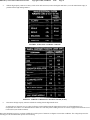
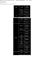
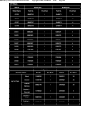
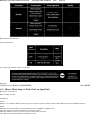
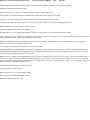
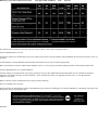
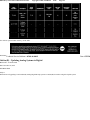
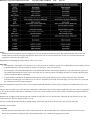
The table lists the HVAC system doors and the DTC associated with it.
Correction
Technicians are to perform the normal diagnostic procedures in SI for these concerns. If diagnostics show that the HVAC system door(s) travel below 5
counts (out of the lower range) or above 250 counts (out of the upper range), then update the software calibrations in the HVAC control module. The
new calibrations were made available to dealerships as part of TIS2000 incremental satellite update version 2.5, which was broadcast to dealers in
February 2006.
The new calibrations have been updated to compensate for the actuator overtravel condition, the actuator hunting and the ticking/clicking noises. The
new calibrations effectively eliminate the codes listed above, the default position of the doors associated with the DTCs and opens up the feedback
position value. The new calibrations should not be used unless the vehicle has one or more of the customer concerns listed above or a DTC listed above
has been set. The new calibrations will not correct any other DTC or NC system performance concern.
Warranty Information
For vehicles repaired under warranty, use the table.
Disclaimer
Technical Service Bulletin # 05-08-61-005
Date: 050429
Body/Frame - Revised Crossmember/Body Bolt Service
Bulletin No.: 05-08-61-005
Date: April 29, 2005
SERVICE MANUAL UPDATE
Subject:
Revised Crossmember/Body Mount Bolt Installation Information
Models:
1999-2005 Cadillac Full-Size Pickup and Utility Models
1999-2005 Chevrolet Full-Size Pickup and Utility Models
1999-2005 GMC Full-Size Pickup and Utility Models
This bulletin is being issued to revise all repair procedures that include reinstalling the front engine crossmember-to-frame bolts or any body mount
bolts in the Frame and Underbody sub-section of the Service Manual. Please replace the current information in the Service Manual with the following
information.
The following information has been updated within SI. If you are using a paper version of this Service Manual, please make a reference to this bulletin
on the affected page.
Before reinstalling front engine crossmember-to-frame bolts or any body mount bolts, you must do the following:
2004 Chevy Truck Tahoe 2WD V8-5.3L VIN T
Copyright © 2009, ALLDATA
10.10
1.
Remove all traces of the original thread locking material.
2.
Clean the threads of the bolt with denatured alcohol, or equivalent, and allow to dry.
3.
Apply Thread locker, P/N 12345493, (Canadian P/N 10953488).
Page 29
DisclaimerTechnical Service Bulletin # 03-03-08-002B
Date: 051130
Suspension - Rattles/Squeaks From Front of Vehicle
Bulletin No.: 03-03-08-002B
Date: November 30, 2005
TECHNICAL
Subject:
Rattle/Squeak from Front of Vehicle (Replace Lower Portion of Upper Insulator Assembly)
Models:
2002-2005 Cadillac Escalade, Escalade EXT
2003-2005 Cadillac Escalade ESV
2000-2005 Chevrolet Silverado, Suburban, Tahoe
2002-2005 Chevrolet Avalanche
2000-2005 GMC Sierra, Yukon, Yukon XL
Supercede:
This bulletin is being revised to update the correction and parts information. Please discard Corporate Bulletin Number 03-03-08-002A (Section 03 Suspension).
Condition
Some customers may comment on a rattle or squeak type noise coming from the front of the vehicle.
Cause
The front shock absorber plastic pilot ring may be wearing out, causing the shock to misalign in the insulator.
Correction
DO NOT replace the shock. Replace the lower portion, P/N 15834275 , of the upper insulator assembly using the procedure listed below. This
new insulator has a taller plastic pilot ring that is attached to the metal sleeve to aid in the proper alignment of the insulators.
1.
Remove the front shock absorber. Refer to the Shock Absorber Replacement procedure in the Front Suspension sub-section of the Service
Manual.
2.
Remove the lower portion of the upper insulator from the shock and discard.
3.
Install the new lower portion of the upper insulator to the shock.
Important:
Be sure to center the shock in the frame bracket and tighten the upper mounting nut when the vehicle is on the ground.
4.
Install the front shock absorber. Refer to the Shock Absorber Replacement procedure in the Front Suspension sub-section of the Service Manual.
2004 Chevy Truck Tahoe 2WD V8-5.3L VIN T
Copyright © 2009, ALLDATA
10.10
Page 30
Parts Information
Warranty Information
For vehicles repaired under warranty, use the table.
Disclaimer
Technical Service Bulletin # 99-08-51-007C
Date: 060619
Wheels - Aluminum Wheel Refinishing Recommendations
Bulletin No.: 99-08-51-007C
Date: June 19, 2006
INFORMATION
Subject:
Refinishing Aluminum Wheels
Models:
2007 and Prior Passenger Cars and Trucks (Including Saturn)
2003-2007 HUMMER H2
2006-2007 HUMMER H3
2005-2007 Saab 9-7X
Supercede:
This bulletin is being revised to add additional models and model years. Please discard Corporate Bulletin Number 99-08-51-007B (Section 08 - Body
and Accessories).
This bulletin updates General Motor's position on refinishing aluminum wheels. GM does not endorse any repairs that involve welding, bending,
straightening or re-machining. Only cosmetic refinishing of the wheel's coatings, using recommended procedures, is allowed.
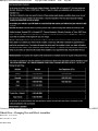
Evaluating Damage
In evaluating damage, it is the GM Dealer's responsibility to inspect the wheel for corrosion, scrapes, gouges, etc. The Dealer must insure that such
2004 Chevy Truck Tahoe 2WD V8-5.3L VIN T
Copyright © 2009, ALLDATA
10.10
Page 31
damage is not deeper than what can be sanded or polished off. The wheel must be inspected for cracks. If cracks are found, discard the wheel. Any
wheels with bent rim flanges must not be repaired or refinished. Wheels that have been refinished by an outside company must be returned to the same
vehicle. The Dealer must record the wheel ID stamp or the cast date on the wheel in order to assure this requirement. Refer to Refinisher's
Responsibility - Outside Company later in this bulletin.
Aluminum Wheel Refinishing Recommendations
^
Chrome-plated aluminum wheels
Re-plating these wheels is not recommended.
^
Polished aluminum wheels
These wheels have a polyester or acrylic clearcoat on them. If the clearcoat is damaged, refinishing is possible. However, the required refinishing
process cannot be performed in the dealer environment. Refer to Refinisher's Responsibility - Outside Company later in this bulletin.
^
Painted aluminum wheels
These wheels are painted using a primer, color coat, and clearcoat procedure. If the paint is damaged, refinishing is possible. As with polished
wheels, all original coatings must be removed first. Media blasting is recommended. Refer to GM Aluminum Refinishing Bulletin # 53-17-03A for
the re-painting of this type of wheel.
^
Bright, machined aluminum wheels
These wheels have a polyester or acrylic clearcoat on them. In some cases, the recessed "pocket" areas of the wheel may be painted. Surface
refinishing is possible. The wheel must be totally stripped by media blasting or other suitable means. The wheel should be resurfaced by using a
sanding process rather than a machining process. This allows the least amount of material to be removed.
Important:
Do not use any re-machining process that removes aluminum. This could affect the dimensions and function of the wheel.
Painting is an option to re-clearcoating polished and bright machined aluminum wheels. Paint will better mask any surface imperfections and is
somewhat more durable than clearcoat alone. GM recommends using Corsican SILVER WAEQ9283 for a fine "aluminum-like" look or Sparkle
SILVER WA9967 for a very bright look. As an option, the body color may also be used. When using any of the painting options, it is recommended
that all four wheels be refinished in order to maintain color uniformity. Refer to GM Aluminum Refinishing Bulletin # 53-17-03A for specific
procedures and product recommendations.
Refinisher's Responsibility - Outside Company
Important:
Some outside companies are offering wheel refinishing services. One such company, Transwheel Corporation (800-892-3733), provides this service
within GM guidelines. Other companies may also exist. Such refinished wheels will be permanently marked by the refinisher and are warranted by
the refinisher. Any process that re-machines or otherwise re-manufactures the wheel should not be used.
A refinisher's responsibility includes inspecting for cracks using the Zyglo system or the equivalent. Any cracked wheels must not be refinished. No
welding, hammering or reforming of any kind is allowed. The wheel ID must be recorded and follow the wheel throughout the process in order to
assure that the same wheel is returned. A plastic media blast may be used for clean up of the wheel. Hand and/or lathe sanding of the machined
surface and the wheel window is allowed. Material removal, though, must be kept to a minimum. Re-machining of the wheel is not allowed. Paint
and/or clear coat must not be present on the following surfaces: the nut chamfers, the wheel mounting surfaces and the wheel pilot hole. The
refinisher must permanently ID stamp the wheel and warrant the painted/clearcoated surfaces fora minimum of one year or the remainder of, the
new vehicle warranty, whichever is longer.
Important:
Whenever a wheel is refinished, the mounting surface and the wheel nut contact surfaces must not be painted or clearcoated. Coating these surfaces
could affect the wheel nut torque.
When re-mounting a tire on an aluminum wheel, coated balance weights must be used in order to reduce the chance of future cosmetic damage.
2004 Chevy Truck Tahoe 2WD V8-5.3L VIN T
Copyright © 2009, ALLDATA
DisclaimerTechnical Service Bulletin # 04-03-16-003
10.10
Page 32
Date: 041130
Tires - Go Flat Slowly/Low Tire Lamp ON
Bulletin No.: 04-03-16-003
Date: November 30, 2004
TECHNICAL
Subject:
Tire Slowly Loses Air, Low Tire Pressure Warning Light On, Check Tire Pressure Message Displayed (Replace Tire Pressure Sensor Grommet)
Models:
2004-2005 Cadillac Escalade, Escalade ESV, Escalade EXT
2004-2005 Chevrolet Suburban, Tahoe
2004-2005 GMC Yukon, Yukon Denali, Yukon XL
with Tire Pressure Monitoring System (RPO UJ6)
Condition
Some customers may comment on a tire that slowly loses air. Also, the Low Tire Pressure Warning light may be illuminated and a Check Tire Pressure
message may be displayed on the DIC.
Cause
If the air loss is determined to be from the valve stem area, then the condition may be caused by the tire pressure sensor sealing grommet. The sealing
grommet is serviced separately from the sensor. Sensor replacement is not required to correct this condition.
Correction
Note:
Tire pressure sensing systems rely on an electronic sensor/transmitters that are located in the drop center of the wheel. Proper care must be taken
during tire mounting and dismounting to avoid sensor damage. When performing tire services, be sure to identify those wheel/tire assemblies that
have a sensor located in the drop center of the wheel.
Proper tools and techniques will help avoid damage to the sensor and the wheel. If you rely on other providers for tire service, select those who can
identify and service TPM equipped wheel/tires without causing unnecessary and expensive damage.
Replace the tire pressure sensor sealing grommet with P/N 25754190, following the Tire Pressure Sensor Grommet Replacement procedure in the Tire
Pressure Monitoring sub-section of the Service Manual.
Parts Information
Parts are currently available from GMSPO.
Warranty Information
2004 Chevy Truck Tahoe 2WD V8-5.3L VIN T
Copyright © 2009, ALLDATA
10.10
Page 33
For vehicles repaired under warranty, use the table.
Technical Service Bulletin # 05-03-08-006
Date: 050412
Suspension - Revised Stabilizer Link Service/Torque
Bulletin No.: 05-03-08-006
Date: April 12, 2005
SERVICE MANUAL UPDATE
Subject:
Revised Stabilizer Shaft Link Replacement Procedure and Fastener Tightening Specifications
Models:
1999-2005 Chevrolet and GMC Full Size Pickup and Utility Models
2003-2005 HUMMER H2
This bulletin is being issued to revise the Stabilizer Shaft Link Replacement Procedure and Fastener Tightening Specifications in the Front Suspension
sub-section of the Service Manual. Please replace the current information in the Service Manual with the following information.
The following information has been updated within SI. If you are using a paper version of this Service Manual, please make a reference to this bulletin
on the affected page.
The following revision affects both the Fastener Tightening Specifications and the Stabilizer Shaft Link Replacement procedure.
Pickup and Utility Models : Stabilizer Shaft Link Nuts - 10 Nm (89 lb in)
Continue tightening the nut until 2 to 4 threads protrude above the nut.
H2 : Stabilizer Shaft Link Nuts - 14 Nm (124 lb in)
Continue tightening the nut until 2 to 4 threads protrude above the nut.
The following Notice has been added to the Stabilizer Shaft Link Replacement procedure.
Note:
To avoid stabilizer shaft damage due to loss of clamp load, the threads of the link bolt must protrude 2 to 4 threads above the nut after the specified
torque is achieved.
DisclaimerTechnical Service Bulletin # 01-03-10-009A
Wheels - Plastic Wheel Nut Covers Loose/Missing
Bulletin No.: 01-03-10-009A
Date: 040727
2004 Chevy Truck Tahoe 2WD V8-5.3L VIN T
Copyright © 2009, ALLDATA
10.10
Page 34
Date: July 27, 2004
TECHNICAL
Subject:
Plastic Wheel Nut Covers Missing and/or Loose (Replace Missing Covers and Add Sealant to All Covers)
Models:
2005 and All Prior Passenger Cars (Except All Cadillac Models and Pontiac GTO)
with Plastic Wheel Nut Covers
Supercede:
This bulletin is being revised to add additional models years. Please discard Corporate Bulletin Number 01-03-10-009.
Condition
Some customers may comment that the plastic wheel nut covers are missing and/or loose.
Correction
Important:
^ DO NOT USE a silicone-based adhesive.
^
Do not apply the *permatex(R) around the threads in a circular pattern.
^
Apply a single bead across the threads approximately 10 mm (0.4 in) in length, 5 mm (0.2 in) in height and 5 mm (0.2 in) in width.
Replace any missing plastic wheel nut covers with the appropriate covers and apply Permatex(R) # 2 Form A Gasket Sealant(R) to the threads of all the
plastic wheel nut covers. Tighten finger tight plus a 1/4 turn with a hand wrench.
*We believe this source and their products to be reliable. There may be additional manufacturers of such material.
General Motors does not endorse, indicate any preference for or assume any responsibility for the products from this firm or for any other such items
which may be available from other sources.
Permatex(R) # 2 Form A Gasket Sealant(R) part numbers (available at your local parts supplier)
^
^
^
^
^
P/N 80009 (2A/2AR) - 44 ml (1.5 oz) tube boxed
P/N 80015 (2AR) - 44 ml (1.5 oz) tube carded
P/N 80010 (2B/2BR) - 89 ml (3 oz) tube boxed
P/N 80016 (2BR) - 89 ml (3 oz) tube carded
P/N 80011 (2C) - 325 ml (11 oz) tube boxed
Warranty Information
For vehicles repaired under warranty, use the table.
2004 Chevy Truck Tahoe 2WD V8-5.3L VIN T
Copyright © 2009, ALLDATA
10.10
Page 35
Disclaimer
Technical Service Bulletin # 03-08-98-002A
Date: 041011
Body - Squeeze Type Resistance Spot Welding/Equipment
Info - Squeeze Type Resistance Spot Welding/Equipment #03-08-98-002A - (Oct 11, 2004)
Squeeze Type Resistance Spot Welding/Equipment
2005 and Prior Passenger Cars and Trucks
2005 and Prior HUMMER H2
This bulletin is being revised to add the 2005 model year and include new equipment offerings. Please discard Corporate Bulletin Number
03-08-98-002 (Section 08 - Body and Accessories).
This bulletin provides guidelines for repair shops that wish to use squeeze type resistance spot welding (or simply, spot welding) as an alternative to
MIG plug welding when performing collision repair procedures. The process of spot welding for attaching body panels and components has been
around for many years and is similar to the production welding process used in assembly plants. Spot welding may be applicable in similar situations
that are currently MIG plug welded.
The following are some of the benefits of spot welding:
- Less heat or burn damage
- Less damage to corrosion protection
- Drilling of holes not required
- Replication of the production weld appearance
Applicable components for this technology may be panels or components with flanges that are accessible with arms and tips supplied by the equipment
manufacturer. Welds from this equipment should be applied on a one-for-one basis, next to the production welds.
Here are some of the important factors in proper welding with this equipment.
Important: Proper use and safety training for each user of the equipment is a must.
-
-
Use equipment from companies that are able to produce welds that meet industry standards for size and strength. Equipment most likely to meet
those standards at this time would be "inverter" technology and include the following suppliers (other suppliers may have comparable
equipment):
- Pro Spot (PR2000)
- Elektron (M100)
- Blackhawk (WEL700)
- Car-O-Liner (CR500) For specific information about this and other equipment, call GM Dealer Equipment at 1-800-GM-TOOLS
(1-800-468-6657).
Ensure that the building power source is capable of meeting the equipment manufacturer's power requirement specifications. For example, fuse
60 amp, 208-230 V single or 3-phase, using supply wire of sufficient gage to carry the current load. Consult with a qualified electrician for
wiring assistance.
Prepare and perform sample welds for destructive testing made from similar materials. Perform this operation for each vehicle repaired and prior
to actual repair.
Proper equipment maintenance
Proper weld tip alignment and maintenance
Ensure that metal flanges are clean and conform to each other
A more complete description of these practices and standards can be found in the following publications:
- SAE J-2667, Surface Vehicles Recommended Practice, http://www.sae.org
- AWS D8.7-88, Recommended Practices Automotive Weld Quality - Resistance Spot Welding, http://www.aws.com
- AWS D8.9-97, Recommended Practices for Test Methods for Evaluating the Resistance Spot Welding Behavior of Automotive Sheet Steels,
http://www.aws.comTechnical Service Bulletin # 04-08-98-001
Date: 040526
Body - Metal Panel Bonding Additional Material
2004 Chevy Truck Tahoe 2WD V8-5.3L VIN T
Copyright © 2009, ALLDATA
10.10
Page 36
Info - Additional Material and Source for Metal Panel Bonding Adhesives #04-08-98-001 - (May 26,2004)
Additional Material and Source for Metal Panel Bonding Adhesives
2004 and Prior Passenger Cars and Trucks
2004 and Prior HUMMER H2
Recently, General Motors reviewed an additional source and material for the bonding of certain exterior metal panels when performing collision repairs.
The 3M Corporation has introduced a new epoxy adhesive. 3M P/N 8116 has been recognized as meeting the performance guideline requirements of
GM 6449G Specification for Metal Panel Bonding Adhesives.
The addition of this product to the materials recognized for this performance capability increases the number to four, thus providing options for material
selection when repairing vehicles using the metal panel bonding process. Those recognized materials now included.
As always, follow the manufacturer's directions for application and curing times. Do not intermix products between different manufacturers. Technical
Service Bulletin # 04-08-64-003A
Date: 040225
Body - Front/Rear Door Power Windows Inoperative
Bulletin No.: 04-08-64-003A
Date: Febuary 25, 2004
INFORMATION
Subject:
Power Window Motor Now Available Separately From The Power Window Regulator Assembly
Models:
2000-2004 Cadillac Escalade
2002-2004 Cadillac Escalade EXT
2003-2004 Cadillac Escalade ESV
1999-2004 Chevrolet Silverado
2000-2004 Chevrolet Suburban, Tahoe
2002-2004 Chevrolet Avalanche
1999-2004 GMC Sierra
2000-2004 GMC Yukon, Yukon XL
with Power Windows (RPO A31)
Supercede:
This bulletin is being revised to update information about window regulator availability. Please discard Corporate Bulletin Number 04-08-64-003
(Section 08 - Body and Accessories).
This Service Bulletin is intended to inform technicians that the power window motor is now available separately from the power window regulator
assembly for both the front and rear doors on the vehicles listed above. A failure of the power window motor in a front door should be repaired by the
replacement of the power window motor only. Regulator failures will require the replacement of the window motor/regulator assembly. For power
window motor replacement instructions, refer to the applicable Window Regulator Motor Replacement procedure in SI.
Important:
2004 Chevy Truck Tahoe 2WD V8-5.3L VIN T
Copyright © 2009, ALLDATA
10.10
Page 37
The replacement of the complete front door power window regulator assembly, due to a power window motor failure, should not be performed as a
warranty repair.
The rear power window motors are also available separately from the power window regulator assembly. The rear power window regulator assembly is
not available without the power window motor. If diagnosis leads to a power window motor failure in a rear door, but the power window regulator still
works, the entire power window regulator assembly should not be replaced as a warranty repair. Replace either the power window motor or the power
window regulator. If diagnosis leads to a power window regulator failure in a rear door, but the power window motor still works, the entire power
window regulator assembly will have to be replaced.
Parts Information
The front window motor part numbers shown are applicable to vehicles from the 1999 to 2004 model years. The rear window motor part numbers
shown are applicable to vehicles from the 2000 to 2004 model years.
Parts are currently available from GMSPO.
Warranty Information
For vehicles repaired under warranty, use the table.
2004 Chevy Truck Tahoe 2WD V8-5.3L VIN T
Copyright © 2009, ALLDATA
10.10
Page 38
DisclaimerTechnical Service Bulletin # 03-08-64-037B
Date: 040615
Body - Power Window Motor Noisy/Inoperative
Bulletin No.: 03-08-64-037B
Date: June 15, 2004
INFORMATION
Subject:
Diagnostic Information For Front Power Window Noisy or Inoperative
Models:
2003-2004 Cadillac Escalade, Escalade ESV, Escalade EXT
2003-2004 Chevrolet Avalanche, Silverado, Suburban, Tahoe
2003-2004 GMC Sierra, Sierra Denali, Yukon, Yukon XL, Yukon Denali, Yukon Denali XL
Supercede:
This bulletin is being revised to close the engineering investigation and provide possible causes of the concern. Please discard Corporate Bulletin
Number 03-08-64-037A (Section 08 - Body and Accessories).
Due to the high number of window regulators being replaced for the front power window being noisy or inoperative and the returned parts indicating
No Trouble Found, an engineering investigation was launched.
The engineering investigation has revealed two probable causes for the power windows being noisy or inoperative.
^
There may be loose regulator bolts. This would primarily lead to a noise condition.
^
The regulator may not be positioned correctly. This could lead to a noise condition as well as causing the window to bind.
ATTEMPT THE FOLLOWING REPAIRS PRIOR TO REPLACING THE WINDOW REGULATOR.
^
^
Loose Regulator Bolts
Tighten
Tighten the bolts to 9 N.m (80 lb in).
Regulator Positioning - verify that the regulator is positioned correctly. If binding, loosen the bolts and adjust.
Tighten
Tighten the bolts to 9 N.m (80 lb in).
If neither of the above corrects the concern, proceed with published diagnostics found in SI.
Warranty Information
2004 Chevy Truck Tahoe 2WD V8-5.3L VIN T
Copyright © 2009, ALLDATA
10.10
Page 39
For vehicles repaired under warranty, use the table.
Disclaimer
Technical Service Bulletin # 05-08-64-038
Date: 051121
Body - Rubbing/Scratching When Operating Windows
Bulletin No.: 05-08-64-038
Date: November 21, 2005
TECHNICAL
Subject:
Rubbing or Scratching Noise When Front Driver or Front Passenger Power Windows Are Activated (Install New Anti-Noise Sleeve on Window
Regulator Support)
Models:
2002-2005 Cadillac Escalade, Escalade EXT
2003-2005 Cadillac ESV
1999-2005 Chevrolet Silverado
2000-2005 Chevrolet Suburban, Tahoe
2002-2005 Chevrolet Avalanche
1999-2005 GMC Sierra
2000-2005 GMC Yukon, Yukon XL
Condition
Some customers may comment on a rubbing or scratching noise when the front driver or front passenger power windows are activated.
Cause
The rubber anti-noise sleeve on the window regulator support may wear through, allowing the window regulator to come in contact with the glass.
Correction
Inspect the rubber anti-noise sleeves on the window regulator support. If either or both are worn, damaged or missing, replace both sleeves (front and
rear) with new polypropylene sleeves, P/N 19120848. Do NOT replace the entire window regulator assembly.
1.
Make sure that the window is closed (glass all the way at the top). Tape the glass to the door header to support the glass.
2.
Remove the door trim upper extension panel. Refer to Trim Panel Replacement - Upper Extension for the appropriate model and model year in
SI.
3.
Remove the door trim panel. Refer to Trim Panel Replacement - Side Front Door for the appropriate model and model year in SI.
4.
Remove the inside door handle. Refer to Door Handle Replacement - Inside for the appropriate model and model year in SI.
5.
Remove water deflector. Refer to Water Deflector Replacement - Front Door for the appropriate model and model year in SI.
6.
Loosen the retaining bolts that hold the window glass to the window regulator assembly. Do NOT remove the bolts.
7.
Reconnect the door electrical harness. Use the window switch to lower the regulator so that the window regulator support that the glass rests on is
accessible through the access hole.
8.
Disconnect the door electrical harness and set the door interior trim piece aside.
2004 Chevy Truck Tahoe 2WD V8-5.3L VIN T
9.
Copyright © 2009, ALLDATA
10.10
Page 40
Inspect the window regulator supports (both front and rear supports).
^
If the rubber anti-noise sleeves are present and NOT damaged or worn, continue with diagnosis of the customer concern. Squeaks may also
occur at the cable/pulley assembly, rail, and/or motor and gearbox housing.
^
If the rubber anti-noise sleeves are damaged or missing, replace the sleeves with new polypropylene sleeves, P/N 19120848.
10.
Reconnect the door electrical harness. Use the window switch to raise the regulator so that glass support is fully supporting the window glass.
11.
Tighten the retaining bolts that hold the window glass to the window regulator assembly.
Tighten
Tighten the bolts to 12 N.m (106 lb in).
12.
Install the water deflector. Refer to Water Deflector Replacement - Front Door for the appropriate model and model year in SI.
13.
Install the inside door handle. Refer to Door Handle Replacement - Inside for the appropriate model and model year in SI.
14.
Install the door trim panel. Refer to Trim Panel Replacement - Side Front Door for the appropriate model and model year in SI.
15.
Install the door trim upper extension panel. Refer to Trim Panel Replacement - Upper Extension for the appropriate model and model year in SI.
16.
Verify that the customer concern has been eliminated.
2004 Chevy Truck Tahoe 2WD V8-5.3L VIN T
Copyright © 2009, ALLDATA
10.10
Page 41
Parts Information
Warranty Information
For vehicles repaired under warranty, use the table.
Disclaimer
Technical Service Bulletin # 05-08-64-029B
Date: 060216
Body - Window Regulator Replacement
Bulletin No.: 05-08-64-029B
Date: February 16, 2006
INFORMATION
Subject:
Power Window Regulator Now Available Separately From Motor
Models:
2002-2006 Cadillac Escalade, Escalade EXT
2003-2006 Cadillac Escalade ESV
2000-2006 Chevrolet Silverado, Suburban, Tahoe
2002-2006 Chevrolet Avalanche
2000-2006 GMC Sierra, Yukon Denali, Yukon XL
Supercede:
This bulletin is being revised to add the service procedure. Please discard Corporate Bulletin Number 05-08-64-029A (Section 08 - Body and
Accessories). This bulletin is being issued to inform technicians that when performing a repair to the power window system, it is no longer necessary to
replace the complete window regulator assembly. GMSPO has released the power window regulator for the left and right front doors separately from
the motor.
Window Regulator Motor Replacement - Front Door
Removal Procedure
1.
Raise the window.
If the window motor is inoperable, remove the window to gain access to the window motor retaining screws. Refer to Window Replacement -
2004 Chevy Truck Tahoe 2WD V8-5.3L VIN T
Copyright © 2009, ALLDATA
10.10
Page 42
Front Door.
2.
Remove the power window module. Refer to Module Replacement - Front Power Window.
3.
With the window regulator on the bench, remove fasteners one (1) and two (2) which will disconnect the drive housing and motor (4) from the
rail (5).
Important:
Do not allow cable gear/spool to come out of the housing. As the motor slides out of the gear/spool, hold the gear/spool into the housing with
your fingers. The spool will unwind if it comes out of the housing.
4.
Holding the motor and housing together, remove fastener three (3).
5.
Slide the motor partially out of the gear/spool allowing finger access to the gear spool (6). Hold the gear/spool into the housing and remove the
motor (7).
Installation Procedure
2004 Chevy Truck Tahoe 2WD V8-5.3L VIN T
Copyright © 2009, ALLDATA
10.10
Page 43
1.
Install motor by aligning gear teeth and mounting points simultaneously, pushing the motor into the gear/spool and installing the motor to
housing fastener first (3).
2.
Slide the motor and housing assembly (4) onto the rail (5) and install the fastener number two (2).
Note:
Refer to Fastener Notice.
3.
Rotate the motor and housing assembly to align the attachment point for attachment number one (1) and install the fastener.
Tighten
Tighten the bolts to 5 N.m (44 lb in).
4.
Install the power window module. Refer to Module Replacement - Front Power Window.
5.
Install the window if removed. Refer to Window Replacement - Front Door.
Important:
The Window Regulator Motor Replacement - Rear Door procedure remains unchanged.
Parts Information
Warranty Information
For vehicles repaired under warranty, use the table.
Disclaimer
Technical Service Bulletin # 03-07-30-056
A/T - 4L60-E Oil Pump Identification
Bulletin No.: 03-07-30-056
Date: 031105
2004 Chevy Truck Tahoe 2WD V8-5.3L VIN T
Copyright © 2009, ALLDATA
10.10
Page 44
Date: November 05, 2003
INFORMATION
Subject:
4L60-E Automatic Transmission Oil Pump First And Second Design Identification
Models:
1997-2002 Chevrolet Camaro
1997-2002 Pontiac Firebird
2002-2004 Cadillac Escalade, Escalade EXT
1997-1999 Chevrolet C/K Full Size Pickup
1997-2004 Chevrolet Astro, Blazer, Corvette, Express, S-10, Suburban
1999-2004 Chevrolet Silverado
2000-2004 Chevrolet Tahoe
2002-2004 Chevrolet Avalanche, TrailBlazer
2004 Chevrolet Colorado, SSR
1997-1999 GMC Suburban
1997-2001 GMC Jimmy
1997-2004 GMC Envoy, Safari, Savana, Sierra, Sonoma
1999-2004 GMC Denali
2000-2004 GMC Yukon, Yukon XL
2004 GMC Canyon
1997-2004 Oldsmobile Bravada
2003-2004 HUMMER H2
with 4L60-E Automatic Transmission (RPOs M30, M32, M33)
The purpose of this bulletin is to identify the correct oil pump rotor (212) and slide (203) usage for the two different transmission oil pump designs.
2004 Chevy Truck Tahoe 2WD V8-5.3L VIN T
Copyright © 2009, ALLDATA
10.10
Page 45
Manufacturing of the first design oil pump rotor (212) and slide (203) ended November 30, 2000.
Manufacturing of the second design oil pump rotor (212) and slide (203) began December 1, 2000.
Important:
It is critical that the first and second design oil pump rotors and slides do not become intermixed. Do not use first design pump components with
second design pump components. If the pump components from either design are intermixed, pump efficiency will be affected resulting in less than
optimal pump performance.
The first design oil pump rotor (212) and slide (203) DO NOT have any identification markings.
The second design oil pump rotor (212) and slide (203) are identified with dimples (circular depression) as shown above.
The rotor (212) has two dimples adjacent to the rotor drive tangs (1).
The slide (203) has one dimple located on the spring tab (2).
DisclaimerTechnical Service Bulletin # 04-07-30-006
A/T - 4L65E, 4L60E, 4L60, 200-4R Oil Pump Spring
Bulletin No.: 04-07-30-006
Date: February 11, 2004
INFORMATION
Subject:
4L65-E, 4L60-E, 4L60 and 200-4R Automatic Transmission Oil Pump Spring First and Second Design Identification
Models:
2004 and Prior Passenger Cars and Light Duty Trucks
2003-2004 HUMMER H2
with 4L65-E, 4L60-E, 4L60 or 200-4R Automatic Transmission
Date: 040211
2004 Chevy Truck Tahoe 2WD V8-5.3L VIN T
Copyright © 2009, ALLDATA
10.10
Page 46
The purpose of this bulletin is to identify the oil pump spring usage for the two different pump designs. Manufacturing of the first design oil pump
springs ended December 15, 2003. Manufacturing of the second design oil pump spring began December 16, 2003
The first design oil pump springs (206) and (207) DO NOT have any identification markings. The first design springs (206) and (207) use an inner and
outer spring, two springs.
The second design oil pump spring (245) is identified with tapered ends on the spring (245) as shown above. The second design spring (245) is a single
spring.
When servicing either (first design or second design) oil pump body, use the new single oil pump spring (245) with tapered ends.
DisclaimerTechnical Service Bulletin # 04-07-30-023
A/T - 4L60-E/4L65-E New Pump/Seal/Case/Service
Bulletin No.: 04-07-30-023
Date: May 12, 2004
INFORMATION
Subject:
Oil Pump Assembly Seal and Transmission Case Change
Models:
Date: 040512
2004 Chevy Truck Tahoe 2WD V8-5.3L VIN T
Copyright © 2009, ALLDATA
10.10
Page 47
2002-2004 Cars and Light Duty Trucks
with 4L60-E or 4L65-E Automatic Transmissions (RPOs M30, M32 or M33)
An improved oil pump to case seal design has been made to the 4L60-E/4L65-E transmission. The new design affects the oil pump, the oil pump seal,
the transmission pan bolts and the transmission case. The complete design was implemented in three phases.
The first phase, beginning in September 2002, relocated the machining of the oil pump 0-ring seal groove in the pump body. The 0-ring seal groove
moved 1.6 mm (0.62 in) inward on the pump body in order to place the sealing surface deeper into the case bore. The relocated pump body groove can
be identified by measuring the groove location. Pump bodies that measure 2.3 mm (0.09 in) from the machined surface to the groove opening have the
relocated 0-ring seal groove. Pump bodies that measure 3.9 mm (0.15 in) are prior to September 2002 design.
The first phase also machined a case chamfer leading into the pump bore (2). The chamfer is designed to help eliminate possible 0-ring seal damage
during pump installation.
2004 Chevy Truck Tahoe 2WD V8-5.3L VIN T
Copyright © 2009, ALLDATA
10.10
Page 48
Phase two modified the case casting and the chamfer into the pump bore. The casting change left additional material in the surrounding pump bore to
allow deeper bore machining in order to create the necessary sealing surface for a new pump seal design. The leading surface into the pump bore was
also machined with a modified chamfer (1).
Phase three will eliminate the oil pump body 0-ring seal groove and the 0-ring seal. Beginning March 2004, a new stamped carrier molded rubber seal
(2) will be used to seal the pump assembly to the transmission case.
The pump sealing surface is now the outer diameter of the pump and the inner diameter (1) of the transmission case bore. Unlike the current 0-ring seal,
which is installed on the oil pump body, the new seal is installed after the pump assembly is properly positioned and torqued in place. Seating the seal is
accomplished when the torque converter housing is installed, which presses the seal (3) into position between the pump and the case bore (1).
2004 Chevy Truck Tahoe 2WD V8-5.3L VIN T
Copyright © 2009, ALLDATA
10.10
Page 49
As a result of the modified casting and the deeper pump bore machining, the area between the oil pan mounting surface and the pump bore has
decreased. Because of the reduced material in this area (1) it is necessary to use the shorter oil pan attaching bolts (2). Early pan bolts (3), before
November 2002, should not be used with the modified case design, since they are 1.0 mm (0.39 in) longer and could deform the chamfer surface (4).
Service Information
When Servicing transmissions with the new seal design, use the following precautions:
^
The outer diameter of the pump assembly and case bore must be clean and free of burrs or raised surfaces. Be aware of sharp edges that could
damage the seal during installation.
^
The seal should be clean and dry before installation. It does not require lubrication for installation.
^
The seal should be inspected prior to installation for obvious damage.
^
It is preferable to hand-start the seal positioning the seal evenly around the case bore before installing the torque converter housing.
^
The seal can be easily removed by prying it out, typical of a pressed-on seal.
^
The seal may be reused, however a thorough inspection must be performed. Inspect the seal for the following conditions:
^
^
Distortion of the metal carrier or separation from the rubber seal.
^
A cut, deformed, or damaged seal.
Refer to the appropriate unit repair information in SI for seal removal and installation procedures.
Parts Interchangeability Information
2004 Chevy Truck Tahoe 2WD V8-5.3L VIN T
Copyright © 2009, ALLDATA
10.10
Page 50
In order to properly service the different designs, it is necessary to correctly identify and select corresponding parts for each level. This table provides a
summary of the part usage for the different design levels.
DisclaimerTechnical Service Bulletin # 03-07-30-027
A/T - Oil Cooler Flushing Frequently Asked Questions
File In Section: 07 - Transmission/Transaxle
Bulletin No.: 03-07-30-027
Date: June, 2003
INFORMATION
Subject:
Most Frequently Asked Questions and Answers for J 45096 TransFlow Transmission Oil Cooling System Flushing Machine
Models:
2004 and Prior Passenger Cars and Light Duty Trucks with Automatic
Transmission/Transaxle
Date: 030601
2004 Chevy Truck Tahoe 2WD V8-5.3L VIN T
Copyright © 2009, ALLDATA
10.10
Page 51
2004 and Prior HUMMER H2
This bulletin is issued to help answer the most frequently asked questions and concerns about essential tool J 45096.
Q: Why doesn't the machine work below 18°C (65°F)?
A: The flow characteristics of ATF at temperatures below 18°C (65°F) does not provide accurate flow test results with the electronics used in the J
45096.
Q: Why didn't the unit come with a tank heater?
A: The vast majority of dealerships do not require a heater to keep the ATF above 18°C (65°F). As a result, the heater was deleted as a cost-savings
measure. A tank heater, J 45096-10, is currently available from Kent-Moore if your dealership requires it. Refer to Corporate Bulletin Number
03-07-30-002A for suggestions on warming the ATF without using a heater blanket.
Q: Why does the machine fail new oil coolers?
A: Several reasons have been found. The most likely reason is the air pressure at the air hose connected to the J 45096 is less than 586 kPa (85 psi).
Other reasons include a twisted hose inside the J 45096 at the bulkhead as a result of the nut turning when the waste or supply hose was installed,
the internal pressure regulator was improperly set at the factory or a problem with the cooler lines on the vehicle. Perform the J 45096 self-test as
described on pages 9 and 10 of the Operation Manual. If a problem is still detected, refer to Troubleshooting on page 19 of the Operation Manual. If
a problem still persists, contact Kent-Moore Customer Service at 1-800-345-2233.
Q: What is the difference between steel and aluminum oil coolers?
A: The aluminum oil cooler tube is slightly thinner in construction than the steel oil cooler tube, which affects the oil flow rate. The fitting that is
protruding out of the radiator tank easily identifies the aluminum oil cooler. Refer to the Quick Reference card provided with the J 45096 in order to
identify the proper flow rate for the aluminum oil cooler.
Q: Why can't I use TransFlow for Allison transmission cooling Systems?
A: Validation of TransFlow is currently under development for light duty trucks equipped with the Allison automatic transmission. TransFlow is based
on the existing MINIMUM flow rate specification through the transmission oil cooling system. The Allison transmission oil cooling system only
has MAXIMUM oil flow rates specified and J 45096 does not have the capability to test the transmission oil cooling system at the maximum oil
flow rate specification.
Q: Why doesn't GM publish a specification for auxiliary transmission oil coolers?
A: The auxiliary oil cooler used with GM vehicles does not contain an internal turbulator plate like the radiator tank oil cooler does. Therefore, there is
no internal restriction that would affect the flow rate through the oil cooling system so a specification for auxiliary oil cooler is not required. Keep in
mind, kinks and damage to the auxiliary cooler and lines can affect the flow rate through the system.
Q: Why did GM drop the labor time for transmission repairs?
A: The labor for flushing and flow testing the transmission oil cooling system is included with the R&R labor of the "K" labor operations that require
transmission removal. The time required to use the J 45096 to perform the flush and flow test is much less than that of the J 35944-A. The warranty
labor savings allowed GM to provide the J 45096 at no cost to dealerships.
Q: Why didn't the machine come with the adapters to hook up to the car?
A: The J 45096 was designed to use the previously released essential cooler line adapters for the J 35944-A. All adapters are listed on page 17 of the
Operation Manual and can be ordered from Kent-Moore at 1-800-345-2233.
Q: How do I connect the J 45096 to a Catera, Prizm or a Vibe?
A: These vehicles, along with many other models, only require barbed fittings to connect to the rubber cooler hose. These fittings are commercially
available and already found in many shops.
Q: Why didn't I receive an Operation Manual with the machine?
A: The Operation Manual was packaged in the upper portion of the shipping carton. If the shipping carton was lifted off the base without opening the
top of the carton, the Operation Manual could have been discarded with the carton. Replacement Operation Manual packages can be obtained from
Kent-Moore Customer Service at 1-800-345-2233.
Q: Why can't I re-use the transmission fluid I use for flushing?
2004 Chevy Truck Tahoe 2WD V8-5.3L VIN T
Copyright © 2009, ALLDATA
10.10
Page 52
A: The very fine metal and clutch material debris from the transmission failure in the ATF causes failures with the hall effect speed sensors that are
used to measure the flow rate. To avoid costly repairs, expensive filters, regular maintenance and problems caused by a partially restricted filter, the
filter was not included.
Q: What do I do if I need service on my machine?
A: Call Kent-Moore Customer Service at 1-800-345-2233. The J 45096 has a one-year warranty.
Q: Can I flush and flow engine oil coolers?
A: The engine oil cooler flow rates, the appropriate adapters and an acceptable procedure are currently under development.
DisclaimerTechnical Service Bulletin # 01-07-30-010B
Date: 051001
A/T - Torque Converter Replacement
Bulletin No.: 01-07-30-010B
Date: October 11, 2005
INFORMATION
Subject:
Automatic Transmission/Transaxle Torque Converter Replacement
Models:
All 2006 and Prior GM Passenger Cars and Trucks
2003-2006 HUMMER H2
2006 HUMMER H3
2006 and Prior Saturn Cars and Light Duty Trucks (Except VTi Equipped Vehicles (RPO M16 and M75)
2005-2006 Saab 9-7X
with ALL Automatic Transmissions and Transaxles
Supercede:
This bulletin is being revised to add additional model years and include the HUMMER H3, Saturn and Saab models. Please discard Corporate Bulletin
Number 01-07-30-ObA (Section 07 - Transmission/Transaxle).
The purpose of this bulletin is to help technicians determine when a torque converter should be replaced. Below is a list of general guidelines to follow.
The converter should NOT be replaced if the following apply:
^
DTC P0742 - TCC stuck on is set. This code is almost always the result of a controls condition (i.e. stuck TCC solenoid/valve). Experience has
shown that this code rarely indicates a mechanical concern within the torque converter.
^
The fluid has an odor or is discolored but no evidence of metal contamination.
^
Fine metal particles (traces of metal flakes/gray color to fluid) are found in the converter. This is not harmful to the torque converter.
^
The vehicle has been exposed to high mileage.
^
A small amount of wear appears on the hub where the oil pump drive gear mates to the converter (RWD only). A certain amount of such wear is
normal for both the hub and oil pump gear. Neither the converter nor the front pump assembly should be replaced.
The torque converter should be replaced under any of the following conditions:
^
The vehicle has TCC shudder and/or no TCC apply. First complete all electrical and hydraulic diagnosis and check for proper engine operation. The
2004 Chevy Truck Tahoe 2WD V8-5.3L VIN T
Copyright © 2009, ALLDATA
10.10
Page 53
converter clutch may be damaged. Also, the converter bushing and/or internal 0-ring may be damaged.
^
Evidence of damage to the oil pump assembly, pump shaft, turbine shaft, drive sprocket support and bearing, or metal chips/debris in the converter.
^
Metal chips/debris are found in the converter or when flushing the cooler and the cooler lines.
^
External leaks in the hub weld area, lug weld or closure weld.
^
Converter pilot is broken, damaged, or fits poorly into the crankshaft.
^
The converter hub is scored or damaged.
^
The transmission oil is contaminated with engine coolant, engine oil or water.
If excessive end play is found after measuring the converter for proper end play (refer to Service Manual).
^
If metal chips/debris are found in the fluid filter, or on the magnet, and no internal parts in the unit are worn or damaged. This indicates that the
material came from the converter.
^
The converter has an unbalanced condition which results in a vibration that cannot be corrected by following Converter Vibration Procedures.
^
Blue converter or dark circular ring between lugs. This condition will also require a complete cleaning of the cooler and a check for adequate flow
through the cooler.
^
Converter bearing noise determined by noise from the bell housing area in Drive or Reverse at idle. The noise is gone in Neutral and Park.
If silicon from the viscous clutch is found in the lower pan (4T80-E ONLY).
DisclaimerTechnical Service Bulletin # 04-06-04-051B
Date: 060104
Fuel System - Fuel Injector Maintenance Cleaning
Bulletin No.: 04-06-04-051B
Date: January 04, 2006
INFORMATION
Subject:
Maintenance Cleaning of Fuel Injectors
Models:
2006 and Prior All General Motors Passenger Cars and Trucks
2003-2006 HUMMER H2
2006 HUMMER H3
Supercede:
This bulletin is being revised to add models and model years and update the name and part number of GM Fuel System Treatment. Please discard
Corporate Bulletin Number 04-06-04-051A (Section 06 - Engine/Propulsion System).
General Motors is aware that some companies are marketing tools, equipment and programs to support fuel injector cleaning as a preventative
maintenance procedure. General Motors does not endorse, support or acknowledge the need for fuel injector cleaning as a preventative maintenance
procedure. Fuel injector cleaning is approved only when performed as directed by a published GM driveability or DTC diagnostic service procedure.
Due to variation in fuel quality in different areas of the country, the only preventative maintenance currently endorsed by GM regarding its gasoline
engine fuel systems is the addition of GM Fuel System Treatment PLUS, P/N 88861011 (for U.S. ACDelco(R), use P/N 88861013) (in Canada, P/N
88861012), added to a tank of fuel at each oil change. Refer to Corporate Bulletin Number 03-06-04-030A for proper cleaning instructions.
2004 Chevy Truck Tahoe 2WD V8-5.3L VIN T
Copyright © 2009, ALLDATA
DisclaimerTechnical Service Bulletin # 05-06-04-063
10.10
Page 54
Date: 051012
Engine Controls - MIL ON/Rough Idle/Misfire/DTC's Set
Bulletin No.: 05-06-04-063
Date: October 12, 2005
TECHNICAL
Subject:
LM7, L59 or L33 Engines with Cold Start Rough or Incorrect Idle, Misfire, Malfunction Indicator Lamp (MIL) or Flashing Requiring 02 Sensor
Replacement (Reprogram PCM)
Models:
2004-2005 Cadillac Escalade
2004-2005 Chevrolet Avalanche, Silverado 1500, Suburban, Tahoe
2005 Chevrolet Silverado Hybrid (HP2)
2004-2005 GMC Sierra 1500, Yukon, Yukon XL
2005 GMC Sierra Hybrid (PH2)
with Vortec 5300 5.3L V-8 Engine (VINs T, Z, B - RPOs LM7, L59, L33)
Condition
Some customers may comment on a Malfunction Indicator Lamp (MIL) On or that the MIL is flashing. An actual engine misfire may or may not be felt
along with an incorrect idle speed. Typically this occurs during cold winter months, on cold engine starts. Some vehicles may have been previously
serviced for the same condition. Technicians may also find the following DTCs stored with the Tech 2(R) P0131, P0133, P0134, P0137, P0138, P0140,
P0151, P0153, P0154, P0157, P1133, which may be in conjunction with P0171, P0174, P0300 and P1138.
Cause
Water shock occurs when water droplets are present in the exhaust. The water in the exhaust contacts the sensor element inside the H02 sensor, causing
the H02 sensor element to crack.
Correction
Upon diagnostic investigation, the technician may find that the H02 sensor requires replacement. In addition to replacing the affected H02 sensor, these
vehicles should also be reflashed with the latest PCM calibration. An updated PCM calibration will be available to dealerships as part of TIS 2000
incremental satellite update 11.0 (NAO version 25.010) or greater. Always, make sure your Tech 2 is updated with the latest software version.
Important:
If a DTC P0420 or P0430 is stored along with DTC(s) P0300, the catalytic converter diagnostics in Service Information (SI) must be followed to
determine if the catalytic converters are operating properly.
Warranty Information
2004 Chevy Truck Tahoe 2WD V8-5.3L VIN T
Copyright © 2009, ALLDATA
10.10
Page 55
For vehicles repaired under warranty, use the table.
Disclaimer
Technical Service Bulletin # 03-05-25-007C
Date: 060516
Brakes - Low Speed ABS Activation/No DTC's Set
Bulletin No.: 03-05-25-007C
Date: May 16, 2006
TECHNICAL
Subject:
Antilock Brake (ABS) Activation At Low Speeds (Clean Wheel Speed Sensor Mounting Surface)
Models:
2002-2006 Cadillac Escalade, Escalade EXT
2003-2006 Cadillac Escalade ESV
1999-2006 Chevrolet Silverado
2001-2006 Chevrolet Suburban, Tahoe
2002-2006 Chevrolet Avalanche
2003-2006 Chevrolet Express
1999-2006 GMC Sierra
2001-2006 GMC Yukon, Yukon Denali, Yukon XL, Yukon Denali XL
2003-2006 GMC Savana
2003-2006 HUMMER H2
Supercede:
This bulletin is being revised to provide additional warranty information. Please discard Corporate Bulletin Number 03-05-25-007B (Section 05 Brakes).
Condition
Some customers may comment on ABS activation at low speeds, usually below 8 km/h (5 mph). Upon investigation, the technician will find no DTCs
set.
Cause
The cause of this condition may be an increased air gap between the wheel speed sensor and the hub reluctor ring due to rust and debris built up on the
2004 Chevy Truck Tahoe 2WD V8-5.3L VIN T
Copyright © 2009, ALLDATA
10.10
Page 56
sensor mounting surface.
Correction
Measure AC voltage and clean the wheel speed sensor mounting surfaces.
1.
Raise and support the vehicle. Refer to Lifting and Jacking the Vehicle in the General Information sub-section of the Service Manual.
2.
Disconnect both the front wheel speed sensor connectors at the frame and harness.
3.
Place a Digital Volt Meter (DVM) across the terminals of each wheel speed sensor connector.
4.
Rotate the wheel clockwise approximately one revolution per second. The minimum reading should be at least 350 ACmV's. If the reading is less
than 350 ACmV's, remove the wheel speed sensor. Refer to the applicable Wheel Speed Sensor Replacement procedure in the ABS sub-section
of the Service Manual.
5.
Plug the wheel speed sensor bore in order to prevent debris from falling into the hub during service.
6.
Clean the wheel speed sensor mounting surface using a wire brush, sand paper, emery cloth, scotch brite, or other suitable material. Be sure to
thoroughly clean the wheel speed sensor surface. There should be no rust or corrosion.
7.
Check the sensor head to determine if it has been warped/distorted due to the corrosion build up or other causes. Check the mounting surface on
the sensor head for flatness by placing it on the edge of a metal machinists scale or other suitable straight edge to measure the flatness. Check the
sensor for flatness in multiple (minimum 3) positions/directions. If the sensor head is distorted, replace the sensor.
8.
Apply (spray) two thin coats of the specified rust penetrating lubricant (corrosion inhibitor) to the complete sensor mounting surface on the
bearing hub. Allow to dry for 3-5 minutes between coats. Use ONLY Rust Penetrating Lubricant, P/N 89022217 (Canadian P/N 89022218).
9.
When the corrosion inhibitor is dry to the touch (about 10 minutes), apply a thin layer of bearing grease to the hub surface and sensor 0-ring prior
to sensor installation. Use ONLY Wheel Bearing Lubricant, P/N 01051344 (Canadian P/N 993037).
10.
Install either the original sensor or a new one in the hub. Ensure that the sensor is seated flush against the hub. Refer to the applicable Wheel
Speed Sensor Replacement procedure in the ABS sub-section of the Service Manual.
11.
Place the DVM across the sensor terminals and recheck the voltage while rotating the wheel. The voltage should now read at least 350 ACmV's.
Parts Information
Warranty Information
2004 Chevy Truck Tahoe 2WD V8-5.3L VIN T
Copyright © 2009, ALLDATA
10.10
Page 57
For vehicles repaired under warranty, use the table.
Disclaimer
Technical Service Bulletin # 03-05-25-005
Brakes/Traction Control - Service Stability Displayed
Bulletin No.: 03-05-25-005
Date: August 20, 2003
TECHNICAL
Subject:
Service Stability Message and DTCs C0455 or C0550 Set (Update Vehicle Stability Enhancement System (VSES) Module Software)
Models:
2003-2004 Cadillac Escalade, Escalade ESV, Escalade EXT
2003-2004 Chevrolet Suburban, Tahoe
2003-2004 GMC Denali, Denali XL, Yukon, Yukon XL
with Vehicle Stability Enhancement System (RPO JL4)
Condition
Some customers may comment on one or more of the following concerns:
^
The Service Stability message may be displayed on the DIC (Driver Information Center).
^
The vehicle lighting systems may dim noticeably.
^
The VSES motor may come on unexpectedly.
^
The brake and Anti-Lock Brake System (ABS) telltales may come on and chime. This concern is most common in cold weather.
Date: 030820
2004 Chevy Truck Tahoe 2WD V8-5.3L VIN T
Copyright © 2009, ALLDATA
10.10
Page 58
Technicians may find Diagnostic Trouble Code (DTC) C0455 and/or C0550 set.
Correction
Technicians are to update the VSES module with new software. The new software will be available in TIS version 6.5 scheduled for release on June 15,
2003. All 2004 model year trucks built prior to June 16, 2003 will also need the VSES module software update.
Warranty Information
For vehicles repaired under warranty, use the table.
Disclaimer
Technical Service Bulletin # 04-08-49-006C
Date: 050105
ABS/TCS - Service Stability Message/DTC C0550 Set
Bulletin No.: 04-08-49-006C
Date: January 05, 2005
TECHNICAL
Subject:
Service Stability Message Displayed, DTC C0550 Set (Reprogram EBCM)
Models:
2004-2005 Cadillac Escalade, Escalade ESV, Escalade EXT
2004-2005 Chevrolet Avalanche, Suburban, Tahoe
2004-2005 GMC Yukon, Yukon Denali, Yukon XL
Supercede:
This bulletin is being revised to correct the Subject line. Please discard Corporate Bulletin Number 04-08-49-006B (Section 08 - Body and
Accessories).
Condition
Some customers may comment that while driving downhill and making a turn, the Service Stability message will display in the Driver Information
Center (DIC). This will occur prior to ABS activation and once stopped, the message will go off.
Upon investigation, the technician may find DTC C0550 stored in history.
Cause
The cause of this condition may be that the "Long Accel Gain" parameters in the EBCM are sensitive to certain driving conditions.
2004 Chevy Truck Tahoe 2WD V8-5.3L VIN T
Copyright © 2009, ALLDATA
10.10
Page 59
Correction
Technicians are to reprogram the EBCM with an updated software calibration. This new service calibration was released with TIS satellite data update
version 9.5 available September 20, 2004. As always, make sure your TECH 2(R) is updated with the latest software version.
Warranty Information
For vehicles repaired under warranty, use the table.
Disclaimer
Technical Service Bulletin # 05-05-25-008
Date: 051005
ABS - 'Service Stabilitrak(R)' Message/DTC C0455 Set
Bulletin No.: 05-05-25-008
Date: October 05, 2005
TECHNICAL
Subject:
Service Stabilitrak(R) Message or Intermittent Stabilitrak(R) Activation During Normal Driving, Diagnostic Trouble Code (DTC) C0455
(Inspect/Repair Steering Wheel Position Sensor (SWPS) Connector and Reprogram Electronic Brake Control Module (EBCM))
Models:
2004-2006 Cadillac Escalade Models
2004-2006 Chevrolet Avalanche, Suburban, Tahoe
2004-2006 GMC Yukon Models
with Control, Active Brake (RPO JL4)
Condition
Some customers may comment on a Service Stabilitrak(R) message or intermittent Stabilitrak(R) activation during normal driving.
When interrogating with the Tech 2(R), the technician may find a DTC C0455.
Cause
There are multiple possible causes for this issue. This bulletin will address the two most likely causes.
^
A bent terminal or poor connection at the SWPS may be one possible cause.
^
The vehicle stability enhancement system (VSES) electronic brake control module (EBCM) calibration may be the other possible cause.
Correction
2004 Chevy Truck Tahoe 2WD V8-5.3L VIN T
Copyright © 2009, ALLDATA
1.
Remove the SWPS connector located at the base of the STRG column.
2.
Inspect the SWPS connector terminals for bent of loose terminals.
3.
Inspect the SWPS terminals for bent or loose terminals.
10.10
Page 60
Important:
DO NOT replace the SWPS or connector if bent or loose terminals are found.
4.
If either the SWPS terminals or SWPS connector terminals are bent or loose, repair the terminals.
5.
Reprogram the VSES EBCM with TIS version 9.0 released on 9/04/05 or later.
Warranty Information
For vehicles repaired under warranty, use the table.
Disclaimer
Technical Service Bulletin # 05-05-25-003B
Date: 060222
TCS/ABS - Service Stability Message/Multiple DTC's Set
Bulletin No.: 05-05-25-003B
Date: February 22, 2006
TECHNICAL
Subject:
Service Stability Message On, Diagnostic Trouble Code (DTC) C0131, C0196, C0290 and/or C0292 Set (Inspect/Replace Yaw Rate Sensor/Lateral
Accelerometer and Reprogram Electronic Brake Control Module (EBCM))
Models:
2004-2006 Cadillac Escalade Models
2004-2006 Chevrolet Avalanche, Suburban, Tahoe
2004-2006 GMC Yukon Models
with Control, Active Brake (RPO JL4)
Supercede:
This bulletin is being revised to update model years. Please discard Corporate Bulletin Number 05-05-25-003A (Section OS - Brakes).
2004 Chevy Truck Tahoe 2WD V8-5.3L VIN T
Copyright © 2009, ALLDATA
10.10
Page 61
Condition
Some customers may comment on a Service Stability Message on the Drivers Information Center (DIC).
Diagnosis with a scan tool may indicate a DTC C0131, C0196, C0290 and/or C0292 is set.
Cause
There are two possible causes for this issue. Both possible causes are listed below:
^
An internal fault within the yaw rate sensor/lateral accelerometer, P/N 15189628, may be the first possible cause.
^
The vehicle stability enhancement system (VSES) electronic brake traction control module (EBCM) calibration may be the second possible cause.
DTC Diagnostic Information
^
DTC C0131
^
DTC C0196
^
DTC C0290 or C0292 (w/JL4)
Correction
Follow the procedure below to inspect the part number on the yaw rate sensor/lateral accelerometer.
1.
Inspect the part number on the yaw rate sensor/lateral accelerometer.
2.
Remove the passenger seat from the vehicle in order to gain access to the sensor. Refer to Seat Replacement - Front Bucket in Seats.
3.
Pull the carpet back in order to gain access to the sensor.
Important:
^ OLD yaw rate sensors/lateral accelerometers have a part number on the sensor bracket of P/N 15189628.
IMPROVED yaw rate sensors/lateral accelerometers have a part number on the sensor bracket of P/N 15220053.
4.
Inspect the yaw rate sensor/lateral accelerometer part number located on the sensor bracket.
^
OLD yaw rate sensors/lateral accelerometers have a part number of P/N 15189628.
^
IMPROVED yaw rate sensors/lateral accelerometers have a part number of P/N 15220053.
Important:
Replace the yaw rate sensor/lateral accelerometer, P/N 15189628, with new sensor, P/N 15220053
5.
Remove the nuts retaining the yaw rate sensor/lateral accelerometer to the vehicle.
6.
Disconnect the electrical connector from the yaw rate sensor/lateral accelerometer.
7.
Remove the yaw rate sensor/lateral accelerometer from the vehicle.
8.
Install the new yaw rate sensor/lateral accelerometer, P/N 15220053, to the vehicle.
Note:
Use the correct fastener in the correct location. Replacement fasteners must be the correct part number for that application. Fasteners
requiring replacement or fasteners requiring the use of thread locking compound or sealant are identified in the service procedure. Do not use
paints, lubricants, or corrosion inhibitors on fasteners or fastener joint surfaces unless specified. These coatings affect fastener torque and
joint clamping force and may damage the fastener. Use the correct tightening sequence and specifications when installing fasteners in order to
avoid damage to parts and systems.
9.
Install the nuts retaining the yaw rate sensor/lateral accelerometer to the vehicle.
Tighten
2004 Chevy Truck Tahoe 2WD V8-5.3L VIN T
Copyright © 2009, ALLDATA
10.10
Page 62
Tighten the nuts to 10 N.m (89 lb in).
Important:
The yaw rate reference reset procedure must be performed when replacing the yaw rate sensor/lateral accelerometer.
10.
Perform the YAW rate reference table reset procedure. Refer to Yaw Rate Reference Table Reset Procedure.
11.
Connect the electrical connector to the yaw rate sensor/lateral accelerometer.
12.
Install the carpet.
13.
Install the passenger seat to the vehicle. Refer to Seat Replacement - Front Bucket in Seats.
Important:
Failure to reprogram the EBCM may result in a repeat repair.
14.
Reprogram the EBCM (referred to as the VSES Module in SPS) with the most current VSES software available through SPS. Refer to Service
Programming System (SPS).
Parts Information
Warranty Information
For vehicles repaired under warranty, use the table.
Disclaimer
Technical Service Bulletin # 03-05-24-001A
Brakes - Wheel Cylinder Inspection Guidelines
Bulletin No.: 03-05-24-001A
Date: 050321
2004 Chevy Truck Tahoe 2WD V8-5.3L VIN T
Copyright © 2009, ALLDATA
10.10
Page 63
Date: March 21, 2005
INFORMATION
Subject:
Service Information Regarding Rear Brake Drum Wheel Cylinder Inspections
Models:
2005 and Prior GM Passenger Cars and Trucks
2005 and Prior Saturn Vehicles
with Rear Drum Brakes
Supercede:
This bulletin is being revised add model years and include all GM vehicles. Please discard Corporate Bulletin Number 03-05-24-001 (Section 03 Suspension).
This bulletin provides information on proper inspection of rear drum brake wheel cylinders.
Important:
It is not recommended that dust boots be removed during inspection processes as dirt and debris could contaminate the wheel cylinder bore causing
premature wear of the wheel cylinder. In addition, most bores should look damp and some lubricant may drip out from under the boot as a result of
lubricant being present.
All rear drum brake wheel cylinders are assembled with a lubricant to aid in assembly, provide an anti-corrosion coating to the cylinder bore, and
lubricate internal rubber components. As a result of this lubrication process, it is not uncommon for some amount of lubricant to accumulate at the ends
of the cylinder under the dust boot.
Over time, the lubricant may work its way to the outside of the boot and cause an area of the boot to look damp. Evidence of a damp area on the boot
does not indicate a leak in the cylinder. However, if there is excessive wetness (i.e. drips) coming from the boot area of the wheel cylinder, it could
indicate a brake hydraulic fluid leak requiring wheel cylinder replacement. (Refer to the Wheel Cylinder Replacement procedures in the appropriate
Service Manual.)
DisclaimerTechnical Service Bulletin # 04004
Date: 040601
Recall - Brake Hydroboost Relief Valve Seal Defect
File In Section: Product Recalls
Bulletin No.: 04004
Date: June 2004
F/CMVSS NONCOMPLIANCE RECALL
SUBJECT:
BRAKE HYDRO-BOOST RELIEF VALVE SEAL FRACTURE
MODELS:
2003-2004 CADILLAC ESCALADE, ESCALADE EXT, ESCALADE ESV
2003-2004 CHEVROLET SILVERADO, AVALANCHE, SUBURBAN, EXPRESS
2004 CHEVROLET TAHOE
2003-2004 GMC SIERRA, YUKON, YUKON XL, SAVANA
CONDITION
General Motors has decided that certain 2003 and 2004 model year Cadillac Escalade, Escalade EXT and Escalade ESV; Chevrolet Silverado,
2004 Chevy Truck Tahoe 2WD V8-5.3L VIN T
Copyright © 2009, ALLDATA
10.10
Page 64
Avalanche, Suburban, and Express; GMC Sierra, Yukon, Yukon XL, and Savana; and 2004 model year Chevrolet Tahoe vehicles fail to conform to
either Federal/Canada Motor Vehicle Safety Standard 105, "Hydraulic and Electric Brake System", or Standard 135, "Light Vehicle Brake Systems".
These vehicles may have a relief valve bore within the brake hydro-boost module that is not to specification. An out-of-specification bore could result
in fracture of the relief valve 0-ring seal within the module. If this happens, during braking applications the driver may be able to hear an engine
compartment noise similar to the sound that occurs when the steering wheel is turned to a full stop position. The driver could also experience a slight
increase in steering efforts while braking and parking. Under certain driving conditions, a fractured seal may require a slight increase in the applied
brake pedal effort to achieve the same vehicle deceleration rate as prior to the seal fracture. If this were to occur, it could result in a vehicle crash
without prior warning.
CORRECTION
Dealers are to inspect the hydro-boost module, and replace the relief valve, if necessary.
VEHICLES INVOLVED
2004 Chevy Truck Tahoe 2WD V8-5.3L VIN T
Copyright © 2009, ALLDATA
10.10
Page 65
Involved are certain 2003 and 2004 model year Cadillac Escalade, Escalade EXT and Escalade ESV; Chevrolet Silverado, Avalanche, Suburban, and
Express; GMC Sierra, Yukon, Yukon XL, and Savana; and 2004 model year Chevrolet Tahoe vehicles built within the VIN breakpoints shown.
IMPORTANT:
Dealers should confirm vehicle eligibility through GMVIS (GM Vehicle Inquiry System) prior to beginning recall repairs. [Not all vehicles within
the above breakpoints may be involved.]
For U.S.: For dealers with involved vehicles, a Campaign Initiation Detail Report containing the complete Vehicle Identification Number, customer
name and address data has been prepared and will be loaded to the GM DealerWorld, Recall Information website. The customer name and address data
furnished will enable dealers to follow up with customers involved in this recall.
For Canada & IPC: Computer listings containing the complete Vehicle Identification Number, customer name and address data of involved vehicles
have been prepared, and are being furnished to involved dealers. The customer name and address data will enable dealers to follow up with customers
involved in this recall. Any dealer not receiving a computer listing with the recall bulletin has no involved vehicles currently assigned.
These dealer listings may contain customer names and addresses obtained from Motor Vehicle Registration Records. The use of such motor vehicle
registration data for any other purpose is a violation of law in several states/provinces/countries. Accordingly, you are urged to limit the use of this
listing to the follow-up necessary to complete this recall.
PARTS INFORMATION
Parts required to complete this recall are to be obtained from General Motors Service Parts Operations (GMSPO). Please refer to your "involved
vehicles listing" before ordering parts.
Normal orders should be placed on a DRO = Daily Replenishment Order. In an emergency situation, parts should be ordered on a CSO = Customer
Special Order.
Important
It is estimated that only 20% of involved vehicles will require Valve Kit Repair. Please order parts accordingly.
COURTESY TRANSPORTATION
The General Motors Courtesy Transportation program is intended to minimize customer inconvenience when a vehicle requires a repair that is covered
by the New Vehicle Limited Warranty. The availability of courtesy transportation to customers whose vehicles are within the warranty coverage period
and involved in a product recall is very important in maintaining customer satisfaction. Dealers are to ensure that these customers understand that
shuttle service or some other form of courtesy transportation is available and will be provided at no charge. Dealers should refer to the General Motors
Service Policies and Procedures Manual for Courtesy Transportation guidelines.
2004 Chevy Truck Tahoe 2WD V8-5.3L VIN T
Copyright © 2009, ALLDATA
10.10
Page 66
CLAIM INFORMATION
CUSTOMER NOTIFICATION - For US and CANADA
General Motors will notify customers of this recall on their vehicle (see copy of customer letter shown in this bulletin).
CUSTOMER NOTIFICATION - For IPC
Letters will be sent to known owners of record located within areas covered by the US National Traffic and Motor Vehicle Safety Act. For owners
outside these areas, dealers should notify customers using the sample letter.
DEALER RECALL RESPONSIBILITY - For US and IPC (US States, Territories, and Possessions)
The US National Traffic and Motor Vehicle Safety Act provides that each vehicle that is subject to a recall of this type must be adequately repaired
within a reasonable time after the customer has tendered it for repair. A failure to repair within sixty days after tender of a vehicle is prima facie
evidence of failure to repair within a reasonable time. If the condition is not adequately repaired within a reasonable time, the customer may be entitled
to an identical or reasonably equivalent vehicle at no charge or to a refund of the purchase price less a reasonable allowance for depreciation. To avoid
having to provide these burdensome remedies, every effort must be made to promptly schedule an appointment with each customer and to repair their
vehicle as soon as possible. In the recall notification letters, customers are told how to contact the US National Highway Traffic Safety Administration
if the recall is not completed within a reasonable time.
This bulletin is notice to you that the new motor vehicles included in this recall may not comply with the standard identified above. Under Title 49,
Section 30112 of the United States Code, it is illegal for a dealer to sell a new motor vehicle which the dealer knows does not comply with an applicable
Federal Motor Vehicle Safety Standard. As a consequence, if you sell any of these motor vehicles without first performing the recall correction, your
dealership may be subject to a civil penalty for each such sale.
DEALER RECALL RESPONSIBILITY - ALL
All unsold new vehicles in dealers' possession and subject to this recall must be held and inspected/repaired per the service procedure of this recall
bulletin before customers take possession of these vehicles.
2004 Chevy Truck Tahoe 2WD V8-5.3L VIN T
Copyright © 2009, ALLDATA
10.10
Page 67
Dealers are to service all vehicles subject to this recall at no charge to customers, regardless of mileage, age of vehicle, or ownership, from this time
forward.
Customers who have recently purchased vehicles sold from your vehicle inventory, and for which there is no customer information indicated on the
dealer listing, are to be contacted by the dealer. Arrangements are to be made to make the required correction according to the instructions contained in
this bulletin. A copy of the customer letter is shown in this bulletin for your use in contacting customers. Recall follow-up cards should not be used for
this purpose, since the customer may not as yet have received the notification letter.
In summary, whenever a vehicle subject to this recall enters your vehicle inventory, or is in your dealership for service in the future, you must take the
steps necessary to be sure the recall correction has been made before selling or releasing the vehicle.
Disclaimer
Service Procedure
The following procedure provides instructions for inspecting, and if necessary, replacing the hydraulic brake booster relief valve.
1.
Open the hood.
Important
You may notice that there is a blue epoxy-type material in the center of the relief valve described in the next step. This material will be found
in both the original arid replacement relief valves.
2.
3.
Locate the relief valve (2) on the hydraulic brake booster. The valve is located in the front of the brake booster directly behind the master cylinder
reservoir (1).
^
If the color of the relief valve is metallic yellow or has a brass appearance, then further action is required.
^
If the color of the relief valve is silver or aluminum, continue to the next step.
Important
If present, the stamped number being described in the next step would be on the mounting surface for the master cylinder on the hydraulic
brake booster. The number may be difficult to see if there is any corrosion on the unpainted surface. As a result, it may be necessary to clean
the surface with a piece of emery or sandpaper.
Inspect the hydraulic brake booster at the location shown (4) for a stamped number. The location (4) is the same surface that the master cylinder
mounts on, just above the outboard mounting bolt and nut (5). Also inspect for a paint mark (3) near the master cylinder outboard mounting bolt
(5). If a stamped number is found it will be a 1, 2, 3, or 4. If a paint mark is found, it will be yellow, pink, or white.
^
If a yellow, pink, or white paint mark IS visible, no further inspection or repairs are required. Disregard any stamped number found when a
yellow, pink, or white paint mark is visible.
^
If there are NO paint marks and there IS a stamped number 2, 3, or 4 visible, no further inspection or repairs are required.
2004 Chevy Truck Tahoe 2WD V8-5.3L VIN T
Copyright © 2009, ALLDATA
10.10
Page 68
^
If there are NO paint marks and there IS a stamped number 1 visible, then proceed to the next step.
^
If there are NO paint marks and there are NO stamped numbers visible, then proceed to the next step.
Caution
Care should be taken when working around the accumulator since it contains high-pressure compressed gas and hydraulic fluid.
4.
With the ignition in the OFF position, pump the brake pedal a minimum of ten times.
5.
On van models, remove the two bolts that attach the diagonal brace between the left front fender and radiator support. Remove the brace and the
water deflector that is attached to it.
6.
On all models, remove the two nuts that attach the master cylinder to the hydraulic brake booster. A 13 mm wrench installed on the bolt head may
be required to prevent the bolt from spinning.
Important
On full size pickups and utilities, the bracket that attaches the brake combination valve will need to be removed from the mounting bolts at the
same time that the master cylinder is removed and repositioned in the next step.
Notice
When repositioning the master cylinder in the next step, use care not to pinch, kink, or damage the brake hoses or pipes.
7.
Remove and reposition the master cylinder away from the hydraulic brake booster so that the machined surface on the front of the booster where
the master cylinder was mounted is visible.
8.
Inspect the machined surface that was covered by the master cylinder on the front of the hydraulic brake booster at the location (1) shown for a
stamped number. The stamped number will be a number 1, 2, 3, or 4.
9.
^
If a stamped number 1 is visible, then the relief valve must be replaced. Proceed to the next step.
^
If a stamped number 2, 3, or 4 is visible, then no further action is required. Proceed to Step 14 and reinstall the master cylinder.
^
If no stamped number is visible, then no further action is required. Proceed to Step 14 and reinstall the master cylinder.
Cover the master cylinder with a clean shop towel in order to protect it from fluids or cleaners. Also, place a shop towel under the hydraulic brake
booster to absorb any fluid that may leak out of the unit when the relief valve is removed in the next step.
2004 Chevy Truck Tahoe 2WD V8-5.3L VIN T
10.
Copyright © 2009, ALLDATA
10.10
Page 69
Using the tool (2) included with the new relief valve, unscrew the original relief valve (1) from the hydraulic brake booster.
Notice
DO NOT blow compressed air into the bore or use any commercially available cleaners to flush the valve bore in the next step. This could
damage the booster or master cylinder.
11.
Inspect the two 0-rings on the original valve for signs of damage. If an 0-ring is missing, broken, or damaged, inspect the bore in the hydraulic
brake booster for any pieces or debris using a non-metallic type tool or a clean "lint-free" towel.
Important
A torque wrench must be used when tightening the valve in the next step. In addition, a 3/8 inch drive to 1/4 inch drive adapter will be needed
if your torque wrench is a 3/8 inch drive.
Important
After tightening the NEW relief valve in the next step, a small gap may exist between the head on the valve and the hydraulic brake booster.
This condition is normal.
12.
Insert the NEW relief valve into the bore.
Tighten
Tighten to 17 Nm (13 lb ft).
13.
Using a clean shop towel, clean up any fluid that may have leaked out of the hydraulic brake booster when removing the original valve.
14.
Position the master cylinder (and brake combination valve mounting bracket on full size pickups and utilities) on the mounting bolts on the
hydraulic brake booster.
15.
With the master cylinder mounted flush to the booster, install the nuts.
Tighten
Tighten the nuts to 33 N.m (24 lb ft).
16.
On van models, install the diagonal brace with the water deflector attached to it between the left fender and the radiator. Install the two bolts.
Tighten
Tighten bolts to 25 N.m (18 lb ft).
17.
Start the engine and verify the hydraulic brake booster operation.
18.
Turn the engine OFF and check the power steering fluid reservoir. Add fluid if necessary.
19.
Close the hood.
2004 Chevy Truck Tahoe 2WD V8-5.3L VIN T
Copyright © 2009, ALLDATA
10.10
Page 70
2004 Chevy Truck Tahoe 2WD V8-5.3L VIN T
Copyright © 2009, ALLDATA
10.10
Page 71
Technical Service Bulletin # 89358
Date: 881101
Battery - Diagnosis and Charging
Bulletin No.
File in Group
Number
Corp. Ref. No.
Date
SUBJECT:
T-89-35
8
89
886401R
Nov. 1988
DELCO FREEDOM BATTERY DIAGNOSIS AND CHARGING
MODELS AFFECTED: ALL
This bulletin outlines the following service information:
I.
Battery Storage:
(In-Vehicle storage) Discusses battery storage procedures, parasitic loads, and includes a chart of fuses to pull to
reduce these loads during storage.
II. Warranty Policy:
V.
Briefly discusses new warranty procedure as it pertains
to battery charge and test (as outlined in DSIB 89-I-9).
III. Testing:
Some brief tips for visual inspection and charging
cautions.
IV. Diagnosing Parasitics:
Contains an important procedure required to properly
test 1986-1988 Eldorados and Sevilles and 1987-1988 Allantes for parasitic drains
(recommended for all carlines).
Charging:
Tips relating to quick charging procedures. Also lists other sources of information.
Read all this information. Try recharging a deeply discharged battery; review training materials if necessary. The majority of deeply discharged
batteries can be recharged if proper procedures are followed.
CAUTION: BATTERIES PRODUCE EXPLOSIVE GASES Always shield eyes and face from battery. Cigarettes, flames, or sparks could cause
battery to explode. Do not charge or use booster cables or adjust terminal post connections without proper instructions and training.
CAUTION: BATTERIES CONTAIN SULFURIC ACID WHICH CAN CAUSE SEVERE BURNS
Batteries contain sulfuric acid. Avoid contact with skin, eyes or clothing. In the event of accident, flush with water and call a physician immediately.
I.Battery Storage In Vehicle
Cadillacs have several electronic devices which result in very small but continuous current drains on batteries, commonly referred to as "parasitic
2004 Chevy Truck Tahoe 2WD V8-5.3L VIN T
Copyright © 2009, ALLDATA
10.10
Page 72
loads". Parasitic loads may cause vehicles, not used for an extended period of time, to develop deeply discharged and/or permanently damaged batteries.
Discharged batteries can freeze at temperatures as high as +20~F, causing permanent damage. Batteries that have been frozen should be scrapped.
Never attempt to recharge or use a battery which has been frozen.
To prevent frozen or damaged batteries, assure that the battery green dot is visible before storing the vehicle. The negative battery cable should be
disconnected on vehicles which are not going to be in service within a 30-day period. If this is not possible, batteries should be recharged periodically,
every 30-60 days, until the green dot is visible (see section on charging). NOTE:
Disconnecting the battery may disable any vehicle security/anti-theft systems!
NOTICE:
The ignition switch, headlights, RAP, etc., must be off when connecting or disconnecting battery jumper cables or chargers. Failure to do
so may overstress or damage the ECM or other electronic components. Disconnecting jumper cables with the engine running may cause
voltage surges that could damage headlamp bulbs or other electronic components.
FIGURE 1 - RECOMMENDED FUSES TO PULL TO MINIMIZE PARASITICS DURING STORAGE
When disconnecting the negative battery cable is not practical for storage, Figure 1 can be used to determine which fuses should be pulled to minimize
the parasitic drain. The "Primary" fuse should be pulled and placed in a location in the vehicle where sales and service personnel can easily find and
reinstall it.
The fuse-pull suggestions found below, in Figure 1, are not designed to completely eliminate parasitic load; only disconnecting the battery negative
cable can accomplish this. Rather, it should help eliminate some of the major draws in a convenient manner.
II. Warranty Policy
Following proper testing and parasitic diagnosis procedures are in the best interests of the dealership in light of Warranty Policies and procedures
outlined in DSIB 89-I-9. This bulletin states that Labor Operation N0100, "Battery charge and test", is to be used only in case of new vehicles received
from the carrier with a discharged or "Dark Eye" battery. Recharge and/or replacement of new vehicle batteries on unsold cars in dealer inventory are
the responsibility of the dealership.
2004 Chevy Truck Tahoe 2WD V8-5.3L VIN T
Copyright © 2009, ALLDATA
10.10
Page 73
FIGURE 2 - WARRANTY PROCEDURE UNDER VARIOUS CONDITIONS
If a condition of discharged battery is a customer concern on a delivered vehicle, the root cause of the discharge should be diagnosed and repaired
before the battery is charged and tested. Battery charge and test on delivered vehicles is to be submitted for approval at no more than 0.3 "Other Labor
Hours" and is to accompany the repair operation that corrects the root cause of the discharge. Refer to Figure 2 on the next page.
III. Testing the Battery
A.
Visual Test
Check for obvious damage, such as cracked or broken case or cover that is permitting loss of electrolyte. If obvious damage is noted, replace the
battery. Determine the cause of damage and correct as needed. If battery terminals are severely damaged, for instance loose, burned, or broken,
replacement of the battery is recommended.
Evidence of small amounts of electrolyte leakage, especially around the vent holes, does not necessarily indicate the battery is defective. The
leakage could have been caused by overcharging or tipping of the battery. If a small amount of the electrolyte leakage is detected, the battery
should be fully charged OUT OF THE CAR so that any electrolyte that may escape does not damage the bumper filler panels or other components.
2004 Chevy Truck Tahoe 2WD V8-5.3L VIN T
Copyright © 2009, ALLDATA
10.10
Page 74
FIGURE 3 - BUILT-IN HYDROMETER
B.
Reading Built-In Hydrometer
Look straight down into the built-in hydrometer to observe its reading, clean and use a flashlight if necessary, and tap lightly on top of the
hydrometer to dislodge any trapped air bubbles that might prevent a correct reading. Refer to Figure 3.
IV. Diagnosing Discharged Batteries and Parasitic Battery Drains
All no-start, slow cranking, and/or frequently discharged battery conditions should be thoroughly diagnosed to avoid unnecessary replacement of
batteries. The battery should be charged and load tested in accordance with established service procedures as described in the Cadillac Service
Information Manual before considering battery replacement. Examples of conditions causing low charged or discharged batteries are:
^
^
^
^
^
^
^
Extended storage of vehicles.
Batteries already discharged when vehicle is received, due to handling in transit and at assembly.
Extended cranking periods due to plug fouling.
Accessory lights left on with engine not running (courtesy, glove box, trunk lights).
Insufficient recharge (ampere-hours) of discharged battery.
Charging system problems.
Continuous current draw on battery through parasitic drain.
FIGURE 4 - PARASITIC LOADS BY CARLINE
2004 Chevy Truck Tahoe 2WD V8-5.3L VIN T
Copyright © 2009, ALLDATA
10.10
Page 75
As was discussed previously in "Battery Storage", today's Cadillacs have several electronic devices which result in very small but continuous current
drains on their batteries, commonly referred to as "parasitic loads". A parasitic drain of up to 50mA is considered normal, 30mA being about average.
Any battery draw above 50mA, with ignition off and retained accessory power disabled (if so equipped), is excessive. Figure 4 gives approximate
average values of design parasitic current draw for each carline.
Also, refer to the table of component parasitic loads found above under "Battery Storage". These values should only be used as general guidelines when
diagnosing suspect components.
FIGURE 5 - PROPER PARASITIC LOAD DIAGNOSTIC PROCEDURE
A.
How to Check the Battery Drain (Refer to Figure 5)
When checking any type of current draw, it is important to use an ammeter or digital multimeter to measure the amperage.
The electrical circuitry of most Cadillac vehicles require that the Body Computer Module (BCM) and the Central Power Supply (CPS) get an
initialization charge whenever the battery power is first provided. This initialization occurs with the ignition key in the "OFF" position, and depending
on how long the battery has been disconnected, the initial draw may last from 1 to 3 seconds and can range between 0.5 and 9.0 amps. Therefore, to
prevent misleading readings or unnecessary fuse replacement on the digital multi-meter, J-29125, or similar equipment, the following procedure is
recommended. THIS PROCEDURE is PARTICULARLY CRITICAL ON THE 1987-1988 ALLANTE AND THE 1986-1988 ELDORADO AND
SEVILLE. It is recommended as a good practice for all vehicles.
1.
Disconnect the negative battery cable.
2.
Install a battery side terminal adapter, AC-Delco ST1201 or equivalent, in the negative terminal of the battery.
3.
Install a 3/8 nut, with standard threads (16 UNC) on the negative battery cable attaching screw to assure a good electrical contact with the
lead face on the cable for testing. Yellow or black finish nuts are generally non-conductive and should not be used.
4.
With all lights, accessories, Retained Accessory Power (RAP), and the ignition switch off, connect a high capacity ammeter at least 10 amps
from the negative battery cable to the side terminal adapter. This high capacity ammeter is connected to verify whether or not a high current
draw is occurring at a constant rate. It is this type of high current draw which will blow the fuse in lower capacity ammeters. After the initial
draw occurs, the ammeter reading should drop below 1 amp.
NOTE:
If a high capacity ammeter is not available, install a section of heavy wire (preferably a battery cable) between the existing battery
negative cable and the side terminal adapter. Allow ample time (approximately 30-60 seconds) for the initial draw to occur and
proceed to step 5.
2004 Chevy Truck Tahoe 2WD V8-5.3L VIN T
5.
Copyright © 2009, ALLDATA
10.10
Page 76
With the high capacity ammeter or battery cable section still connected, connect the digital multi-meter, set to the 2000 DCmA range, in
parallel with the high reading ammeter.
FIGURE 4 - PARASITIC LOADS BY CARLINE
FIGURE 6 - SAMPLE COMPONENT PARASITIC LOADS (IN mA)
6.
Disconnect the high capacity ammeter and take the reading with the digital multi-meter.
A current draw of 5OmA or less (see values in Figures 4 and 6) indicates that all lights and accessories are off and that there is no
unexplained current draw. Care should be taken to allow for a time delay before reading the meter on vehicles equipped with Electronic Level
Control (ELC) (not found on Allante).
Due to this initialization process, test lamps CANNOT be used in place of ammeters to diagnose current draw conditions. The voltage drop across the
test lamp prevents the initialization process from occurring.
2004 Chevy Truck Tahoe 2WD V8-5.3L VIN T
Copyright © 2009, ALLDATA
10.10
Page 77
Clamp-On Ammeters:
Clamp-on ammeters may be used if the meter can measure in the milli-amp range and if the meter clamp can fit around all of the battery negative or
positive cables. All of the cables must fit in the clamp with the clamp closed to be sure that all of the parasitics are being measured. Zero the clamp-on
ammeter carefully. Magnetic fields from engine electrical items (generator, ignition, solenoids) and from shop sources (fluorescent lights, power cables)
can alter the clamp-on meter readings. If the parasitic readings are not repeatable, use the series measurement method described in this bulletin.
B.
Determining the Source of the Drain
Once it has been determined that a parasitic drain in excess of 50 mA exists, a visual inspection of the vehicle should be conducted. Check to
see if there are any unwanted lights on, motors running or switches/relays activating.
FIGURE 4 - PARASITIC LOADS BY CARLINE
If no cause for the draw is immediately apparent, it may be possible to narrow in on the source by systematically removing fuses and circuit
breakers, one by one, from the fuse panels. This should be done while monitoring the ammeter so that a disruption of the drain will be
evident. Refer to Figure 4 for average and maximum parasitic loads for various vehicle components.
2004 Chevy Truck Tahoe 2WD V8-5.3L VIN T
Copyright © 2009, ALLDATA
10.10
Page 78
FIGURE 6 - SAMPLE COMPONENT PARASITIC LOADS (IN mA)
Figure 6 gives an approximate indication of typical and maximum parasitic loads by component in milli-amps (mA).
In addition to parasitic loads, a certain amount of self-discharge is always occurring as a result of internal chemical reactions even when the
battery is not connected. The higher the ambient temperature, the greater the amount of self-discharge. This explains why the number of
discharged batteries may increase at your location in very hot weather. The original equipment battery has a much lower rate of self-discharge
than conventional batteries, however, self-discharge at 100 degrees ambient can be as high as 7mA.
V.Battery Charging
Dealership service personnel are advised to refer to Cadillac Serviceman Bulletin T-83-12, Group 6D for detailed instructions on:
1.
2.
3.
4.
Battery Side Terminal Connections
Battery Charging
Charging Time Required
Load Testing
NOTES:
1.
The majority of discharged batteries can be recharged using normal battery charging procedures. Some deeply discharged batteries or batteries
which have been allowed to remain in a discharged state may need a higher charge voltage initially to start the recharging process.
2.
The Freedom battery is more resistant to overcharging damage than conventional batteries. Boost or Quick-Charge settings on battery chargers
may be safely used in most instances. (This is not true of other non-Delco OE batteries and many aftermarket batteries.)
3.
With the battery at room temperature, voltages as high as 15.0 volts to 16.0 volts may be safely used without causing battery damage. Cold
batteries require more voltage to cause them to accept current. Warm batteries will accept less voltage without causing overcharging.
4.
After starting the battery on charge and periodically during the charging process, the battery should be cheeked to assure that it is not
overcharging. Overcharging can be identified by excessive battery case temperature and electrolyte boiling or bubbling (or spewing out the
vents).
^
^
Battery case temperatures of about 125~F is the maximum which should be allowed. Check by hand feel and reduce the charge rate if high
temperatures are found.
Excessive electrolyte bubbling or boiling indicates that the charge voltage is too high and that the battery is being forced to accept too
2004 Chevy Truck Tahoe 2WD V8-5.3L VIN T
Copyright © 2009, ALLDATA
10.10
Page 79
much current. Turn down the charge rate if high temperatures are found.
^
A battery with an internally shorted cell will show signs of overcharging at normally acceptable voltages. If charge voltages of around 13
volts result in overcharging (on a battery at room temperature or cooler), disconnect the battery and check the voltage. Batteries with
internal shorts will exhibit a drop in voltage over time. Batteries with internal shorts should be scrapped.
Technical Service Bulletin # 02-06-03-010A
Date: 040702
Battery - Parasitic Drain
Bulletin No.: 02-06-03-010A
Date: July 02, 2004
INFORMATION
Subject:
Battery Parasitic Drain
Models:
2005 and Prior Passenger Cars and Trucks
2003-2005 Isuzu Light Duty Trucks
Supercede:
This bulletin is being revised to add the 2004 and 2005 model years. Please discard Corporate Bulletin Number 02-06-03-010 (Section 06 - Engine).
In automotive terms, a parasitic drain is an electrical load that draws current from the battery when the ignition is turned off. Some devices, such as the
PCM and the radio memory are intended to draw a very small amount continuously. These draws are measured in milliamps (mA).
In normal use, parasitic drains aren't usually cause for concern, because the battery is replenished each time the vehicle is driven. But, in long-term
parking situations, parasitic drains may discharge the battery enough to cause a no-start condition. New vehicles in dealer stock and airport long-term
parking are two such situations.
An abnormal parasitic drain could be a glovebox or luggage compartment light that remains on but undetected. Or an electronic component may
malfunction and cause a parasitic drain that is larger than normal specification.
Parasitic Drains and On-the-Lot Battery Discharge
Important:
In most cases of discharged batteries in low-age, low-mileage vehicles, proper charging procedures with approved charging equipment is the only
repair necessary.
Here are some rules of thumb that might help relate parasitic drains to how long a battery would last on a parked vehicle. The Reserve Capacity (RC)
rating multiplied by 0.6 gives the approximate available ampere-hours (AH) from full charge to complete rundown. Somewhere between full charge
and complete rundown, the battery will reach a point at which it can no longer start the engine, although it may still operate some of the electrical
accessories.
Using up about 40% of the total available AH will usually take a fully-charged battery to a no-start condition at moderate temperatures of 25°C (77°F).
Put another way, for a typical battery in a storage situation, depleting the available AH by 20 to 30 AH will result in a no-start condition.
Important:
If the battery begins storage at 90% of full charge, reduce the available AH accordingly.
The recommendation for maximum parasitic drain is around 30 mA (0.030 amp). A typical drain today actually falls into the 7-12 mA range, even
though some vehicles do approach the maximum. Multiply the drain (in amps) by the time (in hours) the battery sits without being recharged. The result
is the amount of AH consumed by the parasitic drain. The actual drain may be small, but over time the battery grows steadily weaker.
Here's an example: a vehicle with a 30 mA drain and a fully-charged 70 RC battery will last 23 days. But if that battery is at only 65% of full charge
(green dot barely visible), it is going to last only 15 days before causing a no-start.
Effects of Temperature on a Standing Battery
The parasitic drain will be fairly constant over a range of temperatures. The important temperature is that of the vehicle at the time a start is attempted.
Colder temperature raises the threshold of a no-start by increasing the residual power needed. When the temperature falls to 0°C (32°F), the battery will
be able to put out only about 85% of its normally available starting power, and the engine may need as much as 165% of the usual power to start.
2004 Chevy Truck Tahoe 2WD V8-5.3L VIN T
Copyright © 2009, ALLDATA
10.10
Page 80
The combined effect of these two factors is to reduce the number of days the battery can stand with a parasitic drain. At 0°C (32°F), the battery can
stand only half as long as it could at 25°C (77°F). And at -19°C (0°F), the standing days are reduced to one-fourth.
Temperatures above the moderate climate of 25°C (77°F) increase the battery's internal self discharge. If the battery is in a locale where the temperature
is averaging 32°C (90°F), an additional 5% to 10% of the available ampere-hours will be lost in a month due to self-discharge within the battery. At
temperatures below the moderate range, self-discharge will be low enough to be negligible compared to the parasitic loss.
What the Policies and Procedures Manual Says About Parasitic Drains
Because determining how long a battery may last in a storage situation is not precise, the P & P manual provides a clear-cut policy, excerpted here.
"Discharged batteries can freeze at temperatures as high as 0°C (32°F), causing permanent damage. Other permanent damage may result from allowing
batteries to stand discharged for extended periods."
"To alleviate this condition, the negative battery cable should be disconnected on vehicles which are not going to be in service within a 20 day period,
beginning from the time the vehicle is shipped. If this is not possible, batteries should be recharged periodically, every 20-45 days, until the green eye is
visible."
"Disconnected batteries will slowly discharge, especially with higher temperatures; therefore, even disconnected batteries should be checked every four
months and recharged if necessary."
"Vehicles on display are subject to battery discharge due to drains from courtesy lights and other accessories. Provision to maintain battery state of
charge for these vehicles will be necessary."
Consult your P & P manual for full details.
Tracking Down the Source of a Parasitic Load
If the battery in a vehicle becomes discharged in a shorter time than described earlier, the vehicle may have an out-of-specification parasitic load. Refer
to Service Information (SI) for procedures for locating parasitic drains. Follow these steps:
1.
Build the vehicle.
2.
Select the Engine section.
3.
Select the Engine Electrical sub-section.
4.
Select Diagnostic Information and Procedures.
5.
Select Battery Electrical Drain/Parasitic Load Test.
You will need the J 38758 Parasitic Draw Test Switch and a digital multimeter set to the 10A scale.
Important:
Read the procedure and follow the steps exactly as described in SI. The following is a summary, not the complete procedure.
The test switch permits you to place an ammeter in series with the battery negative cable. Before performing the test, the engine must be run and all
accessories must be operated as instructed. After shutting the ignition off, turn the test switch off. Now, all the current being used by the vehicle is
shunted through the ammeter where it is measured. If the reading is out of specification, the procedure explains how to pinpoint the cause.
A Final Word About Battery Testing
Your dealership has an essential tool, the Midtronics Micro 410 Battery Tester, J 42000. Use it to quickly identify batteries that are serviceable and can
be charged. Refer to Corporate Bulletin Number 02-06-03-006A for more information about this tool.
DisclaimerTechnical Service Bulletin # 04-06-03-016
Date: 041213
2004 Chevy Truck Tahoe 2WD V8-5.3L VIN T
Copyright © 2009, ALLDATA
10.10
Page 81
Battery - Specification Label Clarification
Bulletin No.: 04-06-03-016
Date: December 13, 2004
INFORMATION
Subject:
Battery Specification Label
Models:
2005 and Prior Passenger Cars and Light Duty Trucks
This bulletin is being issued to provide additional information concerning the specification label on OEM batteries. On the upper right corner of the
label is a replacement model number that has a reference to the battery warranty if sold in the aftermarket. Sample label content shown with
replacement model number as 100-6 YR. This number has been known to cause some confusion in the field as customers think that they have a longer
warranty on the battery than the standard 3 year/36,000 mile (60,000 km) or 4 year/50,000 mile (80,000 km) vehicle warranty.
ACDelco(R) established this model number as part of their cataloging system and it is provided only for replacement information. The warranty code (6
YR) only applies to retail sales. The battery warranty is the same as the vehicle warranty.
If a battery is replaced during the vehicles warranty period, instruct the customer that the new battery will continue to be covered for the remainder of
the vehicle warranty or 12 months/12,000 miles (in Canada, 3 months/6,500 km), whichever is longer.
DisclaimerTechnical Service Bulletin # 04-06-03-001
Date: 040203
Alternator - Incorrect Amperage Coding
Bulletin No.: 04-06-03-001
Date: February 03, 2004
INFORMATION
Subject:
Incorrect Amp Code On Generator
Models:
2003-2004 Cadillac Escalade, Escalade ESV, Escalade EXT
2003-2004 Chevrolet Avalanche, Express, Silverado, Suburban, Tahoe
2003-2004 GMC Denali XL, Savana, Sierra, Yukon, Yukon XL
2003-2004 HUMMER H2
The purpose of this bulletin is to inform the technician of an incorrect Amp code stamped on the generator. The code on the side of the generator reads
130 A and it should read 145 A. The 130 A has been stamped on the generators in error and does not indicate the actual amperage of the generator. A
130 A generator is not produced for this vehicle. The correct replacement for the above vehicles is the generator with the 145 A marking.
2004 Chevy Truck Tahoe 2WD V8-5.3L VIN T
Copyright © 2009, ALLDATA
10.10
Page 82
DisclaimerTechnical Service Bulletin # 04-06-03-002
Date: 040205
Ignition Switch - Intermittent No Crank/Dead Battery
Bulletin No.: 04-06-03-002
Date: February 05, 2004
INFORMATION
Subject:
Diagnostic Information for Intermittent Vehicle No Crank/Dead Battery
Models:
2004 Buick Rainier
2000-2004 Cadillac Escalade
2002-2004 Cadillac Escalade EXT
2003-2004 Cadillac Escalade ESV
1998-2004 Chevrolet Blazer, S-10 Pickup
1999-2004 Chevrolet Silverado
2000-2004 Chevrolet Suburban, Tahoe
2002-2004 Chevrolet Avalanche, TrailBlazer, TrailBlazer EXT
2003-2004 Chevrolet Express
1998-2004 GMC Jimmy/Envoy, Sonoma
1999-2004 GMC Sierra
2000-2004 GMC Yukon, Yukon XL
2002-2004 GMC Envoy, Envoy XL
2003-2004 GMC Savana
2004 GMC Envoy XUV
1998-2004 Oldsmobile Bravada
2003-2004 HUMMER H2
When diagnosing a concern regarding an intermittent vehicle no crank or dead battery, technicians should remove and reinstall the ignition switch using
the Ignition Switch Replacement procedure in the Steering Wheel and Column section of SI. The ignition switch may have been misindexed in the
steering column during a previous replacement.
If the ignition switch is misindexed in one direction, the ignition switch circuits will not be completely open when the ignition switch is in the OFF
position with the key removed. This may result in lights remaining on or instrument panel lights illuminating, which will drain the battery. If the
ignition switch is misindexed in the opposite direction, the ignition circuits will open correctly but the ignition switch may not close the crank circuit
properly when the ignition key is turned to the crank position. This will result in a no crank concern.
DisclaimerTechnical Service Bulletin # 05-06-01-006
Engine Controls - Noise at Idle/Steering Wheel Vibration
Engine Vibration/Noise at Idle, Vibration Felt in Steering Wheel/Seat (Reprogram PCM) # 05-06-01-006 - (Feb 9, 2005)
Models:
2003-2005 Cadillac Escalade
2003-2005 Chevrolet Tahoe
2003-2005 GMC Yukon
Date: 050209
2004 Chevy Truck Tahoe 2WD V8-5.3L VIN T
Copyright © 2009, ALLDATA
10.10
Page 83
with 4.8L or 5.3L Engine (VINS V, T, Z, - RPOs LR4, LM7, L59)
Condition
Some customers may comment on an engine vibration or noise while the vehicle is in gear at idle. This vibration can be felt in the steering wheel or seat
and may intensify if the A/C is turned on. It should be noted that if the engine speed is raised or lowered approximately 50 RPMs, the vibration/noise
will be reduced or go away.
Correction
A new service calibration has been released to lower the engine idle speed to 538 RPM in park/neutral and 525 RPM in gear. Before installing the new
calibration, use the Tech 2(R) and go into Powertrain/Special Functions/TAC System Engine Speed Control and when the condition is duplicated
(engine running, in gear, foot on the brake, A/C on), command the idle down to 525 RPM. If the condition greatly improves or goes away, reprogram
the PCM with the Updated software calibration. This new calibration was released with TIS satellite data update version 1.75 available January 26,
2005. As always, make sure your Tech 2(R) is updated with the latest software version.
Also, if the vehicle is a 2004 model, Corporate Bulletin Number 04-06-01-023 may need to be performed.
Warranty Information
DisclaimerTechnical Service Bulletin # 05-07-30-013
Date: 050509
Engine Controls - 4L60E/4L65E A/T 2nd Gear Start
Bulletin No.: 05-07-30-013
Date: May 09, 2005
TECHNICAL
Subject:
4L60-E/4L65-E Automatic Transmission Second Gear Start, Lack/Loss of Power When Accelerating From a Stop (Reprogram Powertrain Control
Module (PCM)
Models:
2004-2005 Cadillac Escalade
2004-2005 Chevrolet Avalanche, Express, Silverado, Suburban, Tahoe
2004-2005 GMC Savana, Sierra, Yukon
2004-2005 HUMMER H2
with 4L60-E (RPO M30) or 4L65-E (RPO M32) Automatic Transmission
Condition
Some customers may comment on a slip on launch, low power on a launch or a second gear start when accelerating from a stop.
2004 Chevy Truck Tahoe 2WD V8-5.3L VIN T
Copyright © 2009, ALLDATA
10.10
Page 84
This condition is usually very intermittent, occurring only once in a few thousand miles of driving.
A Tech 2 or VDR snapshot of the event may show 2nd gear being commanded for approximately two seconds, then 1st gear commanded as would be
expected.
Cause
This condition may be caused by an intermittent VSS signal, which causes the PCM to command second gear.
Important:
There are other conditions that can cause the transmission to start in a gear higher than first. The following are a few of these conditions.
^
Some DTCs can cause the transmission to start in a higher gear. Check for the presence of DTCs and repair as appropriate before proceeding.
^
Debris on top of the spacer plate or in the valve body or a leaking shift solenoid can cause a 4L60-E or 4L65-E transmission to start in a gear
higher than first. A start in a higher gear caused by any of these conditions typically occurs with much greater frequency. Refer to Service
Bulletin 01-07-30-036D or newer for diagnostic information of these conditions.
^
Placing the shift lever in the D2 position will cause a 4L60-E or 4L65-E transmission to start in second gear. Correction
Important:
^ This bulletin ONLY applies to 2004-2005 models year vehicles listed above.
^
1.
Some DTCs can cause the transmission to start in a higher gear. Check for the presence of DTCs and repair as appropriate before
proceeding.
Using a scan tool, check for the presence of DTCs. If DTCs are present, refer to the appropriate SI Document before proceeding with this
calibration.
Important:
These calibrations also contain the 2-3 shift clunk calibration as detailed in bulletin 05-07-30-012.
2.
Technicians are to reprogram the PCM with an updated software calibration. This new service calibration was released with TIS satellite data
update version 5 or later available May 1, 2005. Refer to Service Programming System (SPS) in Vehicle Control Systems in the appropriate SI
Document.
Warranty Information
For vehicles repaired under warranty, use the table.
Disclaimer
Technical Service Bulletin # 04-08-48-001B
A/C - Broken Rear Window Defogger Grid Detection
Date: 050628
2004 Chevy Truck Tahoe 2WD V8-5.3L VIN T
Copyright © 2009, ALLDATA
10.10
Page 85
Bulletin No.: 04-08-48-001B
Date: June 28, 2005
INFORMATION
Subject:
Rear Window Defogger - Broken Heating Grid Detection Method
Models:
2006 and Prior Passenger Cars and Light Duty Trucks (Including Saturn)
2003-2006 HUMMER H2
2006 HUMMER H3
Supercede:
This bulletin is being revised to add the 2006 model year and additional models. Please discard Corporate Bulletin Number 04-08-48-001A (Section 08
- Body and Accessories).
The addition of vertical grid lines to the heated back window defogger circuits has made it difficult to detect broken defogger grid lines. In the past, it
was a simple matter to use a voltmeter to check the continuity of each grid line in order to locate a non-functional line. Some new design back windows
have two vertical grid lines that connect all of the horizontal grid lines together, thereby providing alternate routes for the electrical current to follow.
This makes the old test method ineffective. If the vehicle does not have the vertical lines, the old (line-by-line) test methods can be used.
Materials Required
^
Permatex(R) Quick Grid, GM P/N 12346001, or equivalent
^
A small ball of fine steel wool Type 00, or
^
Optional - A strip of liquid crystal heat sensitive paper, 51 mm x 305 mm (2 in x 12 in) or similar size (Contact Edmund Scientific at 800-728-6999
for part number CR30723-70 or go to www.scientificsonline.com), or
^
Optional-A portable infrared thermometer, GE-46819, available from Kent-Moore (1-800-345-2233), or equivalent.
Correction
There are three distinct zones across the back window that must be checked. They are:
^
the driver's side outboard of the two vertical lines
^
the passenger side outboard of the two vertical lines
^
the central zone that falls between the two vertical lines
To detect a broken grid line in any of the above three zones and to isolate the exact location of the break, perform the following steps:
Caution:
^ Approved safety glasses and gloves should be worn when performing this procedure to reduce the chance of personal injury.
^
Cover the rear shelf area to prevent damage to the interior trim material.
1.
Start the engine and turn on the back window defogger.
2.
Take the ball of fine steel wool and twist one end to a point. Move the point slowly across each grid line. Be sure to start at the far side of the
zone and move it to the opposite side of the zone. When you bridge the grid line break with the steel wool, you will see a small spark. Repeat the
test over the same area to be sure you have accurately located the break. Mark the exact location of the grid line break. Repeat this portion of the
test for each grid line. If you do not see a spark at any point, it is possible that there are two breaks in the same line and zone. Close visual
inspection using a magnifying glass may be the only way to locate breaks in this case.
3.
The following are provided as an alternative way to detect a non-functional grid line. If available, use in addition to the steel wool.
3.1.
Method using liquid crystal heat sensitive paper:
Important:
The first part of the test must be completed quickly before the entire surface of the back window becomes warm.
2004 Chevy Truck Tahoe 2WD V8-5.3L VIN T
Copyright © 2009, ALLDATA
10.10
Page 86
3.1.1. From outside the vehicle, place the heat sensitive paper (dull surface in contact with the glass) against the top driver side grid line. Start the
engine and turn on the back window defogger. A distinct color change will take place at each conductive grid line. Repeat for the bottom
grid lines until they have all been checked in the driver side zone.
3.1.2. Repeat the process for the passenger side and center area zones.
3.1.3. If no color change is noted for a grid line, place a crayon or china marker check mark beside it. Mark each grid line in the zone where it is
non-conductive and, therefore, not heating up. More than one broken grid line may be found.
3.2.
Method using portable infrared thermometer:
3.2.1. Start the engine and turn on the rear back window defogger.
3.2.2. From inside the vehicle, start at the top driver side grid line and slowly run the portable infrared thermometer vertically down the rear
window contacting each grid line. You should be able to see a district variation in temperature readings.
3.2.3. Mark each grid line in the zone where it is non-conductive and, therefore, not heating up. More than one broken grid line may be found.
3.2.4. Repeat the process for the passenger side and center area zones.
4.
Use Permatex(R) Quick Grid, GM P/N 12346001, or equivalent, to repair each broken grid line. Follow the manufacturer's instructions.
5.
Wait 24 hours before turning the defogger on, or the repair can be fast cured using a heat gun, 260 °C - 371°C (500°F - 700°F). Hold the heat gun
within 25 - 51 mm (1-2 in) from the repair point for 2 to 3 minutes.
6.
Recheck the grid line with the heat sensitive paper or portable infrared thermometer to ensure that the line is now functional and that the repair
was successful.
DisclaimerTechnical Service Bulletin # 05-08-50-017
Date: 051214
Interior - Power Seat Switch Knobs Loose/Missing
Bulletin No.: 05-08-50-017
Date: December 14, 2005
TECHNICAL
Subject:
Power Front Seat (RPO AN3) Switch Knobs Loose or Missing (Replace Switch Knobs)
Models:
2002-2006 Cadillac Escalade, Escalade EXT
2003-2006 Cadillac Escalade ESV
2002-2006 Chevrolet Avalanche, Silverado, Suburban, Tahoe
2002-2006 GMC Sierra, Yukon, Yukon XL
with Individual Front Seat Non-Bucket (RPO AN3) and Driver Front Seat Power Adjuster (AG1) and/or Passenger Front Seat Power Adjuster (AG2)
Condition
Some customers may comment that the power front seat adjuster switch knobs are loose and fall off or are missing.
Correction
2004 Chevy Truck Tahoe 2WD V8-5.3L VIN T
Copyright © 2009, ALLDATA
10.10
Page 87
Replace the front seat adjuster switch knob. These knobs were formerly available only as part of the power seat adjuster switch. DO NOT replace the
switch if the knob only needs to be replaced.
Parts Information
Warranty Information
For vehicles repaired under warranty, use the table.
Disclaimer
Technical Service Bulletin # NHTSA05V163000
Recall 05V163000: 2nd Row Seat Belt Modification
MAKE/MODELS:
MODEL/BUILD YEARS:
CADILLAC / ESCALADE
CHEVROLET / AVALANCHE
2003-2005
2003-2005
CHEVROLET / SILVERADO
2003-2005
CHEVROLET / SUBURBAN
2003-2005
Date: 050422
2004 Chevy Truck Tahoe 2WD V8-5.3L VIN T
CHEVROLET / TAHOE
Copyright © 2009, ALLDATA
10.10
Page 88
2003-2005
GMC / SIERRA
2003-2005
GMC / YUKON
2003-2005
HUMMER / H2
2004-2005
MANUFACTURER: General Motors Corp.
NHTSA CAMPAIGN ID NUMBER: 05V163000 RECALL DATE: April 22, 2005
COMPONENT: Seat Belts: Rear
POTENTIAL NUMBER OF UNITS AFFECTED: 1359824
SUMMARY:
On certain crew cab pickup trucks and sport utility vehicles, the 2nd row center occupant seat belt routing may make it difficult to position the lap
portion of the safety belt low around the hips of occupants, especially smaller occupants, seated in this position. Appropriate use of a child seat or
booster seat, as recommended for small children, does improve the fit condition for this user group. In addition to instructions on proper infant and
young child restraint (with child seats or boosters), special verbiage for restraining older child is included in the owner's manual text.
CONSEQUENCE:
A lap portion of the seat belt routing that is not low and snug on the hips can allow the lap belt to ride up on an occupant's abdomen instead of fitting
low around their hipbones, and therefore, can expose them to more risk of abdominal and internal organ injury.
REMEDY:
Dealers will cut open the guide loop, remove a portion of the loop, and then the remaining two sides should be folded over and secured with a retainer.
The manufacturer has not yet provided an owner notification schedule for this campaign. Owners should contact Cadillac at 1-866-982-2339, Chevrolet
at 1-800-630-2438, GMC at 1-866-996-9463, or Hummer at 1-800-732-5493.
NOTES:
GM recall No. 05037. Customers can also contact The National Highway Traffic Safety Administration's Auto Safety Hotline at 1-888-327-4236.
Technical Service Bulletin # 05037
Date: 050714
Recall - 2nd Row Center Seat Belt Loop Modification
Second Row Center Safety Belt
# 05037 - (Jul 14, 2005)
Models:
2003-2005 CADILLAC ESCALADE, ESCALADE ESV, ESCALADE EXT
2003-2005 CHEVROLET AVALANCIE, SILVERADO CREW CAB, SUBURBAN, TAHOE
2003-2005 GMC SIERRA CREW CAB, YUKON, YUKON XL
2004-2005 HUMMER H2
Condition
General Motors has decided that a defect, which relates to motor vehicle safety, exists in certain 2003-2005 Cadillac Escalade, Escalade ESV, Escalade
EXT; Chevrolet Avalanche, Silverado Crew Cab, Suburban, Tahoe; GMC Sierra Crew Cab, Yukon, Yukon XL; and 2004-2005 HUMMER H2
vehicles. On these vehicles, the seat loop in the second row center seating position may make it difficult to position the lap portion of the safety belt low
around the hips of the occupant. In the event of a vehicle accident, if the lap portion of the safety belt routing is not low and snug on the hips, it may not
properly restrain the occupant and could increase the risk of abdominal injury.
Correction
Dealers are to eliminate the seat loop by removing the safety belt from the loop and stitching the loop closed.
Vehicles Involved
2004 Chevy Truck Tahoe 2WD V8-5.3L VIN T
Copyright © 2009, ALLDATA
10.10
Page 89
2004 Chevy Truck Tahoe 2WD V8-5.3L VIN T
Copyright © 2009, ALLDATA
10.10
Page 90
Involved are certain 2003-2005 Cadillac Escalade, Escalade ESV, Escalade EXT; Chevrolet Avalanche, Silverado Crew Cab, Suburban, Tahoe; GMC
Sierra Crew Cab, Yukon, Yukon XL; and 2004-2005 HUMMER H2 vehicles built within the VIN breakpoints shown.
Important:
Dealers should confirm vehicle eligibility through GMVIS (GM Vehicle Inquiry System) prior to beginning recall repairs. [Not all vehicles within
the above breakpoints may be involved.]
For US and Canada
For dealers with involved vehicles, a Campaign Initiation Detail Report containing the complete Vehicle Identification Number, customer name and
address data has been prepared and will be loaded to the GM DealerWorld (US) Recall Information, GMinfoNet (Canada) Recall Reports. Dealers will
not have a report available if they have no involved vehicles currently assigned.
For Export
For dealers with involved vehicle, a Campaign Initiation Detail Report containing the complete Vehicle Identification Number, customer name and
address data has been prepared, and is being furnished to involved dealers. Dealers will not receive a report with the recall bulletin if they have no
involved vehicles currently assigned.
The Campaign Initiation Detail Report may contain customer names and addresses obtained from Motor Vehicle Registration Records. The use of such
motor vehicle registration data for any purpose other than follow-up necessary to complete this recall is a violation of law in several
states/provinces/countries. Accordingly, you are urged to limit the use of this report to the follow-up necessary to complete this recall.
Parts Information
2004 Chevy Truck Tahoe 2WD V8-5.3L VIN T
Copyright © 2009, ALLDATA
10.10
Page 91
Service Procedure
1.
Note the position of the rear seats.
2.
Position the seats to gain access to the lower seat belt anchor stud for the rear center seat.
3.
Remove any cover necessary to gain access to the lower seat belt anchor point for the rear center seat.
4.
Remove the nut (1) retaining the rear center seat's lower seat belt anchor (seat back shown in the up position).
5.
Remove the belt anchor point from the stud.
6.
Remove the belt from the seat loop on the front of the seat back cushion.
7.
Route the belt outside of the seat loop and install it on the lower anchor stud. Be sure that the belt is not twisted.
8.
Install the retaining nut to the anchor stud.
Tighten
Tighten the retaining nut to 53 Nm (39 lb ft).
9.
Using an appropriate color of locally obtained upholstery thread and needle (size 16 recommended), sew the retaining loop closed in the center.
10.
Reposition the seats to the customer's original position as noted in Step 1
Courtesy Transportation -- for US and Canada
The General Motors Courtesy Transportation Program is intended to minimize customer inconvenience when a vehicle requires a repair that is covered
by the New Vehicle Limited Warranty. The availability of courtesy transportation to customers whose vehicles are within the warranty coverage period
and involved in a product recall is very important in maintaining customer satisfaction. Dealers are to ensure that these customers understand that
shuttle service or some other form of courtesy transportation is available and will be provided at no charge. Dealers should refer to the General Motors
2004 Chevy Truck Tahoe 2WD V8-5.3L VIN T
Copyright © 2009, ALLDATA
10.10
Page 92
Service Policies and Procedures Manual for courtesy transportation guidelines.
Claim Information
Submit a Product Recall Claim with the information shown.
Customer Notification -- For US and Canada
General Motors will notify customers of this recall on their vehicle (see copy of customer letter shown this bulletin).
Customer Notification -- For Export
Letters will be sent to known owners of record located within areas covered by the US National Traffic and Motor Vehicle Safety Act. For owners
outside these areas, dealers should notify customers using the sample letter.
Dealer Recall Responsibility -- For US and Export (US States, Territories, and Possessions)
The US National Traffic and Motor Vehicle Safety Act provides that each vehicle which is subject to a recall of this type must be adequately repaired
within a reasonable time after the customer has tendered it for repair. A failure to repair within sixty days after tender of a vehicle is prima facie
evidence of failure to repair within a reasonable time. If the condition is not adequately repaired within a reasonable time, the customer may be entitled
to an identical or reasonably equivalent vehicle at no charge or to a refund of the purchase price less a reasonable allowance for depreciation. To avoid
having to provide these burdensome remedies, every effort must be made to promptly schedule an appointment with each customer and to repair their
vehicle as soon as possible. In the recall notification letters, customers are told how to contact the US National Highway Traffic Safety Administration
if the recall is not completed within a reasonable time.
Dealer Recall Responsibility -- All
All unsold new vehicles in dealers' possession and subject to this recall MUST be held and inspected/repaired per the service procedure of this recall
bulletin BEFORE customers take possession of these vehicles.
Dealers are to service all vehicles subject to this recall at no charge to customers, regardless of mileage, age of vehicle, or ownership, from this time
forward.
Customers who have recently purchased vehicles sold from your vehicle inventory, and for which there is no customer information indicated on the
dealer listing, are to be contacted by the dealer. Arrangements are to be made to make the required correction according to the instructions contained in
this bulletin. A copy of the customer letter is shown in this bulletin for your use in contacting customers. Recall follow-up cards should not be used for
this purpose, since the customer may not as yet have received the notification letter.
2004 Chevy Truck Tahoe 2WD V8-5.3L VIN T
Copyright © 2009, ALLDATA
10.10
Page 93
In summary, whenever a vehicle subject to this recall enters your vehicle inventory, or is in your dealership for service in the future, please take the
steps necessary to be sure the recall correction has been made before selling or releasing the vehicle.
Disclaimer
2004 Chevy Truck Tahoe 2WD V8-5.3L VIN T
Copyright © 2009, ALLDATA
10.10
Page 94
2004 Chevy Truck Tahoe 2WD V8-5.3L VIN T
Copyright © 2009, ALLDATA
10.10
Page 95
Technical Service Bulletin # 05-08-110-003
Date: 050324
Air Bag System - Passenger Air Bag Discolored
Bulletin No.: 05-08-110-003
Date: March 24, 2005
INFORMATION
Subject:
Information on Cleaning Discolored Passenger Side Air Bag Cover
Models:
2000-2005 Chevrolet and GMC Full Size Pickups and Utilities
with Passenger Side Air Bag
The passenger side air bag module cover may be discoloring. DO NOT replace the air bag module for discoloring concerns. The discoloring is a salt
that is formed on the air bag cover surface as a result of a chemical reaction between the polyester cover material and gases originating from urethane
components in the vehicle.
Clean the air bag cover with a nonabrasive liquid soap (such as liquid dish soap or liquid hand soap) and warm water solution.
DisclaimerTechnical Service Bulletin # 04-08-64-016
Lighting - Rear Door Puddle Lamp Reflector Replacement
Bulletin No.: 04-08-64-016
Date: 040809
2004 Chevy Truck Tahoe 2WD V8-5.3L VIN T
Copyright © 2009, ALLDATA
10.10
Page 96
Date: August 09, 2004
INFORMATION
Subject:
Rear Door Puddle Lamp Reflector Replacement
Models:
2004 Cadillac Escalade, Escalade ESV, Escalade EXT
2004 Chevrolet Avalanche, Suburban, Tahoe
2004 GMC Denali, Denali XL, Yukon, Yukon XL
The purpose of this service bulletin is to announce that when replacement of a rear door interior trim panel puddle lamp/reflector is necessary, replace
ONLY the reflector. The reflector is available separately and replacement of the complete door trim panel is not necessary. Use the applicable reflector
part number listed below.
Using a small screwdriver, pry from the rear outer edge to remove the reflector.
Parts Information
Parts are currently available from GMSPO.
Warranty Information
For vehicles repaired under warranty, use the table.
Disclaimer
Technical Service Bulletin # 04-08-49-018E
Fuel System - Cranks But No Start/Inaccurate Fuel Gauge
Date: 050105
2004 Chevy Truck Tahoe 2WD V8-5.3L VIN T
Copyright © 2009, ALLDATA
10.10
Page 97
Bulletin No.: 04-08-49-018E
Date: January 05, 2005
TECHNICAL
Subject:
Cranks But No Start, Stall, Inaccurate/Incorrect Fuel Gauge Reading, No Fuel, Vehicle is Out of Fuel and Fuel Gauge Reads Above Empty (Replace
Fuel Level Sensor)
Models:
2001-2004 Cadillac Trucks
1999-2004 Chevrolet and GMC Trucks
with Gasoline Engine (VINs Z, X, V, T, U, N, G, 6, 8 - RPOs LU3, LR4, LM7, LQ4, LQ9, L59, L18,LK5 L52)
Attention:
Parts are currently available for vehicles with Variable Fuel (VIN Z - RPO L59) vehicles. Please refer to Corporate Bulletin Number 04-06-04-01
2B or newer for Variable Fuel (VIN Z - RPO L59) vehicles.
Supercede:
This bulletin is being revised to include information on the Chevrolet Colorado and the GMC Canyon. Please discard Corporate Bulletin Number
04-08-49-018D (Section 08 - Body and Accessories).
Condition
Some customers may comment on the vehicle stalling and will not restart, vehicle ran out of fuel, vehicle appears to be out of fuel but the fuel gauge
reads above empty. The fuel gauge may read 1/4 tank.
Cause
Contamination on the fuel sending card may cause inaccurate/incorrect fuel gauge readings.
Correction
Follow the service procedure below for diagnosis and repair of this concern.
1.
Confirm that the vehicle is actually out of fuel.
^
If the vehicle is not out of fuel but Engine Cranks but Does Not Run, refer to the appropriate Service Information.
^
If the vehicle is out of fuel and the gauge does not read empty, test the fuel gauge. Refer to the following information:
-
Fuel Gage Inaccurate or Inoperative Single Tank
-
Fuel Gage Inaccurate or Inoperative Dual Tanks
-
Fuel Gage Inaccurate or Inoperative Colorado and Canyon
2.
If testing reveals that the fuel gauge is operating correctly, replace the fuel sensor assembly and auxiliary tank fuel level sensor if equipped.
3.
Replace the fuel level sensor. Refer to the following appropriate service information:
^
Fuel Level Sensor Replacement 4.8L and 5.3L Engines
^
Fuel Level Sensor Replacement 6.0L Engine - Front Tank
^
Fuel Level Sensor Replacement 6.0L Engine - Rear Tank
^
Fuel Level Sensor Replacement 8.1L vehicles with Front Tank
^
Fuel Level Sensor Replacement 8.1 L vehicles with Rear Tank
2004 Chevy Truck Tahoe 2WD V8-5.3L VIN T
Parts Information
Parts are currently available from GMSPO.
Warranty Information
Copyright © 2009, ALLDATA
10.10
Page 98
2004 Chevy Truck Tahoe 2WD V8-5.3L VIN T
Copyright © 2009, ALLDATA
10.10
Page 99
For vehicles repaired under warranty, use the table.
Disclaimer
Technical Service Bulletin # 02-08-42-001B
Date: 041008
Lighting - Damage To Polycarbonate Headlamp Lenses
Info - Chemical Damage to Exterior Polycarbonate Headlamp Lenses #02-08-42-001B - (Oct 8, 2004)
Chemical Damage To Exterior Polycarbonate Headlamp Lenses
2005 and Prior Passenger Cars and Trucks
2003-2005 HUMMER H2
This bulletin is being revised to add the 2004 and 2005 model years. Please discard Corporate Bulletin Number 02-08-42- 001A (Section 08 - Body and
Accessories).
The bulletin is being issued to make dealers and customers aware of chemical damage that may be caused to exterior polycarbonate headlamp lenses.
Most late model vehicles have these types of headlamp lenses. This material is used because of its temperature and high impact resistance.
A variety of chemicals can cause crazing or cracking of the headlamp lens. Headlamp lenses are very sensitive. Care should be exercised to avoid
contact with all exterior headlamp lenses when treating a vehicle with any type of chemical, such as those recommended for rail dust removal. Rubbing
compound, grease tar and oil removers, tire cleaners, cleaner waxes and even car wash soaps in too high a concentration may also attribute to this
condition. This could result in the need to replace the entire headlamp housing.
Also, crazing or deformations of the lens may occur if a shop mat or fender cover is draped over the fender and covers a portion or all of the headlamp
assembly while the DRL or headlamps are on. This action restricts the amount of heat dissipated by the headlamps.
Once a heat buildup is generated by the headlamp, a degradation of the headlamp lens begins. This degradation of the lens can be unnoticeable at first
and eventually manifest as spider cracks. In more extreme cases, it will begin to melt the lens of the headlamp.Technical Service Bulletin #
06-01-38-002
A/C - Hiss Noise From Instrument Panel
Bulletin No.: 06-01-38-002
Date: March 17, 2006
TECHNICAL
Subject:
A/C System Refrigerant Hiss Noise (Replace Liquid Line)
Models:
2003-2006 Cadillac Escalade Models
Date: 060317
2004 Chevy Truck Tahoe 2WD V8-5.3L VIN T
Copyright © 2009, ALLDATA
10.10
Page 100
2003-2006 Chevrolet Avalanche, Silverado, Suburban, Tahoe
2003-2006 GMC Sierra, Yukon Models
with 4.3L, 4.8L, 5.3L, 6.0L or 8.1L Engine (VINs X, V, T, Z, B, U, N, G - RPOs LU3, LR4, LM7, L59, L33, LQ4, LQ9, L18) and Air Conditioning
(RPOs CJ2, CJ3 and C69)
Condition
Some customers may comment on a hiss noise coming from the instrument panel. The noise has also been described as sounding like a gurgle or water
spattering. The noise occurs when the Air Conditioning (A/C) compressor engages and may continue for 5 to 10 seconds after the compressor
disengages or the A/C system is turned off. The noise is most noticeable when the vehicle is at idle or is being driven at low speeds. The noise is
undetectable after about one minute when the A/C system has been turned off or the vehicle has been turned off.
Cause
This condition may be caused by the expanding refrigerant as it passes through the orifice tube.
Correction
Technicians are to verify that the customer concern is only as described in the condition statement above. If the customer concern is a refrigerant hiss
noise, then technicians are to perform the normal diagnostic procedures for an A/C system concern. The ACR2000 should be used to check the A/C
system performance, charge level and discharge temperatures. This will eliminate the possibility that another condition is contributing to this customer
concern. If the A/C system is performing properly, and all other possible sources of this noise are eliminated, then technicians are to replace the A/C
liquid line. Use the proper part number as described in the parts information box below. Verify that the noise has been eliminated and that the A/C
system operates normally.
Parts Information
Important:
The trucks affected by this bulletin that have rear air conditioning were built with two different length condensers. The short condenser is 762 mm
(30.0 in) long. The long condenser is 914 mm (36.0 in) long. Be sure to measure the length of the condenser before ordering one of the tubes listed
below for vehicles with rear air conditioning.
Warranty Information
2004 Chevy Truck Tahoe 2WD V8-5.3L VIN T
Copyright © 2009, ALLDATA
10.10
Page 101
For vehicles repaired under warranty, use the table.
Disclaimer
Technical Service Bulletin # 99-08-51-001A
Date: 051121
Body - Paint-Less Dent Repair Recommendations
Bulletin No.: 99-08-51-001A
Date: November 21, 2005
INFORMATION
Subject:
Paint-less Dent Repair Process
Models:
2006 and Prior GM Passenger Cars and Trucks
2003-2006 HUMMER H2
2006 HUMMER H3
2005-2006 Saab 9-7X
with Steel Outer Body Panels
Supercede:
This bulletin is being revised to add model years, models and update the information. Please discard Corporate Bulletin Number 99-08-51-001 (Section
08 - Body and Accessories).
The process of removing dents from vehicles without painting has been around for many years. Over the past several years, General Motors has
evaluated many versions of this process. Most versions were found to be unacceptable because of the potential long-term durability concerns. However,
a new type of repair process has been identified. This process uses special tools requiring no drilling of holes or removal of vehicle components for
access. This process is appropriate for the majority of panels with reasonable access to the back side of the damaged area. The special tools and
procedures that have been developed will remove the dents while eliminating the need to fill, paint, or replace the panel. This type of procedure has
been thoroughly evaluated and the repaired parts were tested for negative impact. No negative impact was found.
Important:
The removal of structural components or drilling of holes in any panel is not recommended and may void the General Motors Corrosion Warranty.
Evaluating Damage
2004 Chevy Truck Tahoe 2WD V8-5.3L VIN T
Copyright © 2009, ALLDATA
10.10
Page 102
Appropriate uses for paint-less dent repair include the following conditions:
^
Dents with no broken paint on the surface. Be sure to inspect for cracks with a 4x magnifying glass.
^
Large or small dents, creases or buckles, small sharp dents and soft dents in body lines and contoured areas that allow reasonable access to the back
side of the damaged area.
^
Dents that do not require structural part removal.
Inappropriate uses for paint-less dent repair include the following situations:
^
Dents that include cracked paint.
^
Dents that require holes to be drilled.
^
Dents that require structural parts to be removed.
^
Sharp dents in contoured areas, dents on the edge of panels, or dents in zero-clearance areas.
Tools
Use tools that are high-quality, tempered steel with smooth polished, rounded tips. These will not damage the back side of the dented area. Typically,
these tools are shaped and bent in order to allow access to most areas of the vehicle without drilling holes in the body as well as provide a clear view of
the work area. Specialty lights are also used to highlight damaged areas.
DisclaimerTechnical Service Bulletin # 04-08-46-005
Date: 041221
OnStar(R) - System Inoperative/No LED Lamp ON
Bulletin No.: 04-08-46-005
Date: December 21, 2004
TECHNICAL
Subject:
OnStar(R) Generation 6 (Digital) System Inoperative/Has No Power, LED Light Not On (Remove/Reinstall OnStar(R) Fuse and Replace VCIM or
Follow SI Diagnostics)
Models:
2004-2005 Buick Rainier, Rendezvous
2005 Buick Allure (Canada), LaCrosse, LeSabre, Terrazza
2004-2005 Cadillac Escalade, Escalade ESV, Escalade EXT
2005 Cadillac CTS, DeVille
2004-2005 Chevrolet Avalanche, Silverado, Suburban, Tahoe, TrailBlazer, TrailBlazer EXT
2005 Chevrolet Colorado, Express, Impala, Monte Carlo, Uplander
2004-2005 GMC Denali, Denali XL, Envoy, Envoy XL, Envoy XUV, Sierra, Yukon, Yukon XL
2005 GMC Canyon, Savana
2004-2005 Pontiac Aztek
2005 Pontiac Bonneville, Grand Prix, Montana SV6, Vibe
with Digital Gen 6 OnStar(R) (RPO UE1)
Condition
Some customers may comment any or all of the following conditions:
^
The OnStar(R) system may be inoperative.
2004 Chevy Truck Tahoe 2WD V8-5.3L VIN T
^
^
Copyright © 2009, ALLDATA
10.10
Page 103
The OnStar(R) system may have no power.
The OnStar(R) LED light may not be on.
The technician may also not be able to communicate with the OnStar(R) Vehicle Communication Interface Module VCIM) with a Tech 2(R).
Correction
Remove the OnStar(R) fuse from the fuse box, wait five minutes and reinstall the fuse. If the OnStar(R) system DOES NOT return to normal
functionality, then follow the diagnostics in SI for this condition.
If the OnStar(R) system DOES return to normal functionality, you will need to replace the VCIM. If the VCIM is not replaced, there is the possibility
that the customer will return to the dealership with the same conditions at a later date.
Please contact the GM Technical Assistance Center (TAC), to obtain a new VCIM. The TAC consultant will verify your diagnosis and, if appropriate,
order a replacement part. Replacement parts are usually shipped out within 24 hours, and a pre-paid return package label will be included for returning
the faulty part. By returning the faulty part, you will avoid a significant non-return core charge. After the VCIM has been replaced, press the blue
OnStar(R) button and request a full reconfiguration.
When contacting TAC regarding this concern, the availability of certain information from the vehicle will streamline the process for the dealership
technician as well as minimize the time necessary for TAC to provide the correct diagnosis. Please refer to Corporate Bulletin Number 01-00-89-011B
for further information concerning the information necessary before contacting TAC. Dealers in Canada should refer to GM Service Policies &
Procedures Section 5.3.1 "DEALER REQUIREMENTS FOR ASSISTANCE".
Warranty Information
For vehicles repaired under warranty, use the table.
Disclaimer
Technical Service Bulletin # 04-08-46-002B
OnStar(R) - Unable to Connect, Bulletin Cancellation
Bulletin No.: 04-08-46-003B
Date: February 07, 2006
INFORMATION
Subject:
Unable to Connect to OnStar(R) or OnStar(R) Personal Calling Inoperative
Models:
2001-2005 GM Passenger Cars and Light Duty Trucks
2003-2005 HUMMER H2
2005 Saab 9-7X
Date: 060207
2004 Chevy Truck Tahoe 2WD V8-5.3L VIN T
Copyright © 2009, ALLDATA
10.10
Page 104
with Analog OnStar System (RPO UE1)
Attention:
This bulletin only applies to vehicles currently in the state of Alaska.
Supercede:
This bulletin is being revised to cancel Bulletin Number 04-08-46-003A. The OnStar issues in Alaska have been corrected. Please discard Corporate
Bulletin Number 04-08-46-003A (Section 08 - Body and Accessories).
This bulletin is being published to cancel Bulletin Number 04-08-46-003A. The issues with OnStar in Alaska have been corrected and dealers no longer
need to follow the information contained in the bulletin.
DisclaimerTechnical Service Bulletin # 02-08-46-010G
OnStar(R) - Programming for Canadian French
Bulletin No.: 02-08-46-010G
Date: March 01, 2006
INFORMATION
Subject:
Programming OnStar(R) Module for Canadian French Voice Recognition (OnStar(R) Generation 5 or Generation 6)
Models:
2003-2005 Buick LeSabre
2003-2006 Buick Rendezvous
2004 Buick Regal
2004-2005 Buick Century
2004-2006 Buick Rainier
2005-2006 Buick Allure (Canada Only), LaCrosse, Terraza
2003 Cadillac CTS, DeVille, Seville
2003-2006 Cadillac Escalades
2004 Cadillac Seville
2004-2005 Cadillac DeVille, XLR
2004-2006 Cadillac CTS, SRX
2005 Cadillac STS
2003-2005 Chevrolet Cavalier, Express, Venture
2003-2006 Chevrolet Avalanche, Silverado, Suburban, Tahoe, TrailBlazer, TrailBlazer EXT
2004-2005 Chevrolet Impala, Malibu, Malibu Maxx, Monte Carlo
2004-2006 Chevrolet Colorado
2005 Chevrolet Cobalt, Corvette, Equinox
2005-2006 Chevrolet Uplander
2003-2005 GMC Savana
2003-2006 GMC Envoy, Envoy XL, Sierra, Yukon, Yukon XL
2004-2006 GMC Canyon
2003 Oldsmobile Aurora
2003-2004 Oldsmobile Bravada, Silhouette
2003-2005 Pontiac Aztek, Bonneville, Montana, Sunfire
2004-2006 Pontiac Grand Prix
2005 Pontiac G6, Pursuit (Canada Only)
2005-2006 Pontiac Montana SV6, Vibe
2003-2006 Saturn ION, VUE
2004 Saturn L-Series
2005-2006 Saturn Relay
2003-2006 HUMMER H2, H2 SUT
Date: 060301
2004 Chevy Truck Tahoe 2WD V8-5.3L VIN T
Copyright © 2009, ALLDATA
2006 HUMMER H3
2005-2006 Saab 9-7X
with OnStar(R) Generation 5 or Generation 6 (RPO UE1)
10.10
Page 105
2004 Chevy Truck Tahoe 2WD V8-5.3L VIN T
Copyright © 2009, ALLDATA
10.10
Page 106
2004 Chevy Truck Tahoe 2WD V8-5.3L VIN T
Copyright © 2009, ALLDATA
10.10
Page 107
2004 Chevy Truck Tahoe 2WD V8-5.3L VIN T
Copyright © 2009, ALLDATA
10.10
Page 108
2004 Chevy Truck Tahoe 2WD V8-5.3L VIN T
Copyright © 2009, ALLDATA
10.10
Page 109
Refer to table for applicable VIN breakpoints.
Attention:
This bulletin is not applicable to vehicles equipped with OnStar(R) Generation 6.1 or later. This bulletin only applies to OnStar(R) Generation 5
and/or 6 with a Station Identification (STID) number in the following range: 9,100,001-13,000,000 or 14,000,001-15,999,999 or
22,000,001-23,200,000.
Supercede:
The bulletin is being revised to include additional models and add the 2006 model year. Please discard Corporate Bulletin Number 02-08-46-010E
(Section 08 - Body and Accessories).
The Gen 5 and 6 OnStar(R) Systems have the capability change the default English voice recognition to French.
Changing the language of the OnStar(R) system will change the following features to the language you select:
^
Voice recognition command prompts will be played in the language selected.
^
The voice recognition system will only recognize commands given in the selected language.
Once completed, this process completely changes all voice recognition and voice commands of the OnStar(R) system. The process will need to repeated
in its entirety to change to a different language, including English.
Important:
If the following steps are NOT completed prior to performing the SPS download, the VCIM will be damaged and will have to be replaced. The
technician must document the error codes displayed on the Tech 2(R) if the calibration fails.
2005-2006 Cadillac SRX
Prior to downloading the French calibration, the Rear Hatch 10 amp fuse muse be removed from the right rear fuse block. After completing the SPS
programming, the fuse must be reinstalled.
2006 Chevrolet Silverado/GMC Sierra 2500/3500 HD Trucks
Prior to downloading the French calibration, the TCM (transmission control module) must be disconnected on vehicles equipped with an Allision(R)
automatic transmission (RPO MW7). After completing the SPS programming, the TCM must be reinstalled.
2004-2005 Pontiac Grand Prix, Buick Allure (Canada Only)
Prior to downloading the French calibration, remove the serial data line (circuit 1037, terminal 38) from connector C1 at the BCM (body control
module). After completing the SPS programming, the data line must be reinstalled.
2004 Chevy Truck Tahoe 2WD V8-5.3L VIN T
Copyright © 2009, ALLDATA
10.10
Page 110
2005 Chevrolet Corvette
Prior to downloading the French calibration, remove the serial data line for the HVAC module (circuit 1038, terminal B) from SP208. After completing
the SPS programming, the data line must be reinstalled.
2005 Buick Rendezvous
After downloading the French calibration, the IPC may display "ERROR". The battery cables may need to be disconnected and reinstalled.
2004 Chevrolet Malibu
Malibu's with an automatic air conditioning (RPO C68) must have the HVAC control module disconnected prior to downloading the French calibration.
After completing the SPS programming, the control head must be reinstalled.
The current modules that require SPS reprogramming are:
-
EBCM (when replaced)
-
PCM (when replaced or updated with new calibrations/programming)
-
OnStar(R) Module (only when language is changed between English and French or back to English)
Service Procedure
Important:
On vehicles with Gen 5 OnStar(R) modules, you will need to obtain the software ID number using a Tech 2. You will need this number later
in the procedure to complete the download. The software ID number is found under ID Information, Module Information 1.
Important:
Please follow each step in its entirety.
Important:
This process does not change the routing of calls to a French-speaking advisor.
1.
Be sure your Tech 2(R) software version is 25.009 or later and the Techline(R) terminal TIS CD is 9.0 (2005) or later.
2.
Turn OFF the ignition.
3.
Install the Tech 2(R) to the Data Link Connector (DLC).
4.
Turn ON the ignition with the engine off.
5.
Turn off all vehicle accessories.
6.
With the Tech 2(R), select F1: Service Programming System (SPS).
7.
Select FO: Request Info on the Tech 2(R).
8.
Verify that the displayed VIN matches the vehicle's VIN. If the displayed VIN does not match the actual VIN, write down the actual VIN and
correct the VIN at the Techline(R) terminal.
9.
When complete, Exit Service Programming.
10.
Turn OFF the Tech 2(R) and disconnect the Tech 2(R) from the vehicle.
11.
Turn OFF the ignition.
12.
Connect the Tech 2(R) to the Techline(R) terminal.
13.
Select Service Programming System.
14.
Select Tech 2(R) as the tool you are using.
15.
Select the type of programming to be performed.
2004 Chevy Truck Tahoe 2WD V8-5.3L VIN T
Copyright © 2009, ALLDATA
10.10
Page 111
16.
Verify the displayed VIN with the vehicle's VIN. Correct the VIN as necessary.
17.
Select OnStar(R) Module. If OnStar(R) does not appear as a selection on the list, please contact the Techline(R) Customer Support Center
(TCSC) for further instructions on the VCI programming option.
18.
Identify what type of programming you are performing.
19.
^
Normal: This type of programming is for updating an existing calibration or programming a new controller.
^
Vehicle Configuration Index (VCI): This selection is used if the vehicle VIN is unavailable or not recognized by the Techline terminal. Please
note that you will need to contact TCSC to use this function.
Select the appropriate calibration.
^
French
^
English
20.
Ensure that all connections are secure.
21.
Select Next to initiate the download of the new calibration to the Tech 2(R).
22.
After the download is complete, turn OFF the Tech 2(R).
23.
Disconnect the Tech 2(R) from the Techline(R) terminal.
24.
Install the Tech 2(R) to the DLC.
25.
Turn ON the Tech 2(R).
26.
Turn ON the ignition with the engine OFF.
27.
Select F1: Service Programming System.
28.
Select F1: Program ECU.
29.
After the download is complete, Exit Service Programming.
30.
Turn OFF the ignition for 30 seconds.
31.
Turn OFF the Tech 2(R).
Programming Verification
1.
Turn ON the ignition.
2.
Press the black button with the white dot. The "OnStar(R) Ready" response should play in the language you downloaded.
3.
Say "Help" in the language downloaded.
4.
The system should respond with a list of available features in the language you just downloaded.
2004 Chevy Truck Tahoe 2WD V8-5.3L VIN T
Copyright © 2009, ALLDATA
10.10
Page 112
Warranty Information
Dealers may submit for reimbursement to change the resident language only once per vehicle. Once per vehicle is defined at changing from the default
language to an alternate language. Changing the language again will require following one of the above processes and will be at the dealer's or owner's
expense.
Warranty Information (Saab U.S. Models)
Dealers may submit for reimbursement to change the resident language only once per vehicle. Once per vehicle is defined at changing from the default
language to an alternate language. Changing the language again will require following one of the above processes and will be at the dealer's or owner's
expense.
DisclaimerTechnical Service Bulletin # 03-09-41-003A
Date: 050209
Restraints - Air Bag System Diagnostics
Info - Proper Air Bag System Diagnosis and Service # 03-09-41-003A - (Feb 9, 2005)
Models:
2004 and Prior Passenger Cars and Light Duty Trucks
Excluding 2004 Pontiac Grand Prix
This bulletin is being revised to remove 2004 Pontiac Grand Prix for the models. Please discard Corporate Bulletin Number 03-09-41-003 (Section 9 Restraints).
This bulletin is being issued to emphasize several aspects of proper diagnosis and servicing of the Air Bag System.
Air Bag Readiness Light
As stated in Owners Manuals, if the air bag readiness light stays on after the vehicle is started, the system may not be working properly. The air bags
may not inflate in a crash or may even inflate without a crash. If the Air Bag Readiness Light/Indicator is illuminated or comes on intermittently,
diagnose to determine the cause. Refer to Air Bag Indicator Circuit Malfunction in the SIR sub-section of the appropriate Service Manual.
Replacement of Soaked SDMs
As stated in Service Manuals, if the vehicle interior is exposed to moisture and becomes soaked up to the level of the sensing and diagnostic module
(SDM), the SDM and SDM harness connector must be replaced. The SDM could be activated when powered, which could cause air bag deployment
and result in personal injury. The air bags, as well as the sensors and related parts, would have to be replaced. To help avoid this situation, turn the
ignition off immediately. DO NOT turn the ignition back on, even to tow the vehicle, unless the battery cable is first disconnected.
Replacement of SDM that Shows Signs of Water Exposure or Corrosion
If an SDM that is being replaced shows signs of water exposure or corrosion and the customer does not know the source of the water exposure, then the
vehicle should be checked for water leaks. If leaks are found, the customer should be advised to have them repaired to help avoid damage to the
2004 Chevy Truck Tahoe 2WD V8-5.3L VIN T
Copyright © 2009, ALLDATA
10.10
Page 113
replacement SDM.
DisclaimerTechnical Service Bulletin # 05-09-41-010
Date: 051222
SRS - New SIR System Disabling Procedure
Bulletin No.: 05-09-41-010
Date: December 22, 2005
INFORMATION
Subject:
New SIR System Disabling and Enabling Procedure
Models:
2003-2006 GM Passenger Cars and Light Duty Trucks (including Saturn)
2003-2006 Chevrolet Kodiak C4500-C8500 Series Medium Duty
2003-2006 GMC TopKick C4500-C8500 Series Medium Duty
2003-2006 HUMMER H2
2006 HUMMER H3
2005-2006 Saab 9-7X
with Supplemental Inflatable Restraint (SIR) System
SIR System Disabling and Enabling
Past experience with Supplemental Inflatable Restraint (SIR) systems enables simplification of the SIR Disabling and Enabling procedure. Testing has
shown that it is not always necessary to disconnect air bag(s) in the area of repairs. Future designs will eliminate certain deployment loop in-line
connectors. The new SIR Enabling and Disabling procedure requires only a fuse removal and/or the negative battery cable disconnect.
The new SIR Enabling and Disabling procedure is less invasive (therefore eliminating potential squeak and rattle conditions that may occur from the
previous procedure) and is a simpler and quicker approach. The labor time for operations requiring SIR disabling will be adjusted as appropriate
according to the new procedure and revisions will appear in future releases of the GM Labor Time Guide.
SIR components are installed in various locations around the vehicle. To find the location of the SIR components, refer to the SIR Identification Views
in the service manual.
2004 Chevy Truck Tahoe 2WD V8-5.3L VIN T
Copyright © 2009, ALLDATA
10.10
Page 114
The information shown covers the proper procedures for disabling/enabling the SIR system.
SIR Service Precautions
Caution:
When performing service on or near the SIR components or the SIR wiring, the SIR system must be disabled. Failure to observe the correct
procedure could cause deployment of the SIR components. Serious injury can occur. Failure to observe the correct procedure could also result in
unnecessary SIR system repairs.
The inflatable restraint Sensing and Diagnostic Module (SDM) maintains a reserved energy supply. The reserved energy supply provides deployment
power for the air bags if the SDM loses battery power during a collision. Deployment power is available for as much as one minute after disconnecting
the vehicle power. Waiting one minute before working on the system after disabling the SIR system prevents deployment of the air bags from the
reserved energy supply.
General Service Instructions
The following are general service instructions that must be followed in order to properly repair the vehicle and return it to its original integrity:
^
Do not expose inflator modules to temperatures above 65°C (150°F).
^
Verify the correct replacement part number. Do not substitute a component from a different vehicle.
^
Use only original GM replacement parts available from your authorized GM dealer. Do not use salvaged parts for repairs to the SIR system.
Discard any of the following components if it has been dropped from a height of 91 cm (3 feet) or greater:
^
Inflatable restraint Sensing and Diagnostic Module (SDM).
^
Any inflatable restraint air bag module.
^
Inflatable restraint steering wheel module coil.
^
Any inflatable restraint sensor.
^
Inflatable restraint seat belt pretensioners.
^
Inflatable restraint Passenger Presence System (PPS) module or sensor.
Disabling Procedure - Air Bag Fuse
1.
Turn the steering wheel so that the vehicle's wheels are pointing straight ahead.
2.
Place the ignition switch in the OFF position.
Important:
The inflatable restraint Sensing and Diagnostic Module (SDM) may have more than one fused power input. To ensure there is no unwanted
SIR deployment, personal injury, or unnecessary SIR system repairs, remove all fuses supplying power to the SDM. With all SDM fuses
removed and the ignition switch in the ON position, the AIR BAG warning indicator illuminates. This is normal operation, and does not
indicate a SIR system malfunction.
3.
Locate and remove the fuse(s) supplying power to the SDM. Refer to SIR Schematics and/or Electrical Center Identification Views.
2004 Chevy Truck Tahoe 2WD V8-5.3L VIN T
4.
Copyright © 2009, ALLDATA
10.10
Page 115
Wait one minute before working on the system.
Enabling Procedure - Air Bag Fuse
1.
Place the ignition switch in the OFF position.
2.
Install the fuse(s) supplying power to the SDM. Refer to SIR Schematics and/or Electrical Center Identification Views.
3.
Turn the ignition switch to the ON position. The AIR BAG indicator will flash then turn OFF.
4.
Perform the Diagnostic System Check - Vehicle if the AIR BAG warning indicator does not operate as described. Refer to Diagnostic System
Check - Vehicle.
Disabling Procedure - Negative Battery Cable
1.
Turn the steering wheel so that the vehicle's wheels are pointing straight ahead.
2.
Place the ignition switch in the OFF position.
3.
Disconnect the negative battery cable(s) from the battery. Refer to the Battery Negative Cable Disconnect/Connect Procedure.
4.
Wait one minute before working on system.
Enabling Procedure - Negative Battery Cable
1.
Place the ignition switch in the OFF position.
2.
Connect the negative battery cable(s) to the battery. Refer to the Battery Negative Cable Disconnect/Connect Procedure.
3.
Turn the ignition switch to the ON position. The AIR BAG indicator will flash then turn OFF.
4.
Perform the Diagnostic System Check - Vehicle if the AIR BAG warning indicator does not operate as described. Refer to Diagnostic System
Check - Vehicle.
DisclaimerTechnical Service Bulletin # 02-06-05-004B
Date: 060214
Accessories - DTC's P0300, P1380, P1381
Bulletin No.: 02-06-05-004b
Date: February 14, 2006
INFORMATION
Subject:
Misfire DTCs P0300, P1380, P1381 and Catalytic Converter Damage Due to Installation of Alarm Systems
Models:
2006 and Prior GM Passenger Cars and Light Duty Trucks
2006 and Prior HUMMER H2, H3
2006 and Prior Isuzu Light Duty Trucks
Supercede:
This bulletin is being revised to add model years. Please discard Corporate Bulletin Number 02-06-05-004A (Section 06 - Engine/Propulsion System).
General Motors Engineering, in an effort to determine the root cause of catalytic converter damage, has determined that aftermarket alarm systems
incorrectly installed in vehicles have the potential to cause misfire codes and damage to the converter. These alarm systems use a circuit interrupt which
utilizes the ignition circuit on the vehicles.
2004 Chevy Truck Tahoe 2WD V8-5.3L VIN T
Copyright © 2009, ALLDATA
10.10
Page 116
These alarm systems utilize mechanical relays and normal vehicle movement can trigger these relays to engage and disengage the ignition circuit while
the vehicle is in motion. These disruptions of the ignition circuit, which occur in milliseconds, may cause more fuel to be commanded. Overtime, this
dumping of fuel on and off again can cause misfire codes and ultimately damage the converter assembly.
Important:
Engineering could not identify any alarms that utilize solid state circuitry that would eliminate this concern. Because of this, it has been determined
that all alarm systems must be routed through the starter circuit in order to avoid this condition.
Dealers must be aware of this issue and take note of the wiring on vehicles with alarm systems that come in for repair, particularly for catalytic
converter damage that seem to have no known root cause.
DisclaimerTechnical Service Bulletin # 02-09-41-002A
Date: 040324
SRS - Air Bag Lamp ON/DTC B0092 Set
Bulletin No.: 02-09-41-002A
Date: March 24, 2004
TECHNICAL
Subject:
Air Bag Lamp On, Passenger Air Bag Indicator Always Reads OFF, DTC B0092 Set (Repair Passenger Presence System (PPS) Sensor Harness)
Models:
2003-2004 Cadillac Escalade, Escalade EXT
2003-2004 Chevrolet Avalanche, Silverado, Suburban, Tahoe
2003-2004 GMC Sierra, Yukon, Yukon XL
with Sensor Indicator Inflatable Restraint Front Passenger/Child Presence Detector (RPO ALO)
Supercede:
This bulletin is being revised to add the 2004 model year. Please discard Corporate Bulletin Number 02-09-41-002 (Section 09 - Restraints).
Condition
Some customers may comment that the Air Bag Lamp is on and the Passenger Air Bag indicator always reads OFF. Upon investigation, the technician
may find DTC B0092 set.
Cause
The cause of this condition may be a shorted Passenger Presence System (PPS) sensor wire. The PPS sensor harness is located under the front
passenger seat. This harness may be pinched between the seat frame and the track/riser.
Correction
2004 Chevy Truck Tahoe 2WD V8-5.3L VIN T
Copyright © 2009, ALLDATA
10.10
Page 117
Locate the PPS sensor (1) and inspect the harness for proper routing. If the harness is pinched between the seat frame and the track/riser, use the
procedure listed below to repair wire(s).
1.
Move the front passenger seat to the full rearward and full tilt up position.
2.
Loosen the seat frame to track/riser nut and remove the harness.
3.
Tighten the seat frame to track/riser nut.
4.
Repair any damaged wires. Refer to Wiring Repairs in the Wiring Systems sub-section of the Service Manual.
Warranty Information
For vehicles repaired under warranty, use the table.
Disclaimer
Technical Service Bulletin # 05-06-04-024
Engine Controls - Revised DTC P1172 & P2636
Bulletin No.: 05-06-04-024
Date: March 17, 2005
SERVICE MANUAL UPDATE
Subject:
Revised DTC P1172 and DTC P2636
Models:
2001-2005 Cadillac Escalade Models
Date: 050317
2004 Chevy Truck Tahoe 2WD V8-5.3L VIN T
Copyright © 2009, ALLDATA
10.10
Page 118
2001-2005 Chevrolet Avalanche, Silverado, Suburban, Tahoe
2001-2005 GMC Sierra, Yukon Models
with 4.8L, 5.3L, 6.0L or 8.1L Engine (VINs V, P, T, Z, U, N, G - RPOs LR4, LM4, LM7, L59, LQ4, LQ9, L18)
This bulletin is being issued to revise Step 29 of DTC P1172 and DTC P2636 in the Engine Controls sub-section of the Service Manual. Please replace
the current information in the Service Manual with the following information.
The following information has been updated within SI. If you are using a paper version of this Service Manual, please make a reference to this bulletin
on the affected page.
Step 29 of both DTC P1172 and DTC P2636 should read - Replace the rear fuel sender assembly.
DisclaimerTechnical Service Bulletin # 05-06-04-029A
Date: 050624
Engine - Rough Idle/Misfire/MIL ON/DTC P0300
Bulletin No.: 05-06-04-029A
Date: June 24, 2005
TECHNICAL
Subject:
Flexible Fuel (RPO L59) Rough Idle, Misfire, MIL DTC P0300
(Install Intake Manifold Gaskets With Teal Green Gasket Material)
Models:
2002-2004 Chevrolet Silverado, Suburban, Tahoe
2002-2004 GMC Sierra, Yukon, Yukon XL
with 5.3L Engine and Flexible Fuel (VIN Z - RPO L59)
This bulletin may apply to the following engines using regular fuel: 4.8L, 5.3L, 6.0L (VINs V, T, P, U, N - RPOs LR4, LM7, LM4, LQ4, LQ9).
Supercede:
This bulletin is being revised to add additional diagnostic information. Please discard Corporate Bulletin Number 05-06-04-029 (Section 06 Engine/Propulsion System).
Important:
Always begin your diagnosis with the Diagnostic System Check - Engine Controls (SI Document ID # 1289827) for any MIL or driveability
concern. The Diagnostic System Check directs you to the next logical step in your diagnosis. Follow the instructions in this bulletin should the
rough idle, misfire, or DTC P0300 diagnostic procedure point to an air leak in the intake manifold gasket. Following the published diagnostic
procedures will improve diagnostic accuracy and support our fix it right the first time approach.
Condition
Some customers may comment that the vehicle may have a rough idle, misfires and/or a MIL illuminated with a stored DTC P0300.
Cause
The L59 engine is calibrated for ethanol fuel (E85). Due to the low volatility of ethanol, the PCM provides higher fuel flow through the injector, which
may pool on the upper manifold to head gasket material. Overtime (usually 12 months and longer), the gasket material may degrade resulting in an
unmetered air leak.
Correction
Replace the upper intake manifold gaskets with the teal green gasket material, P/N 89017589.
2004 Chevy Truck Tahoe 2WD V8-5.3L VIN T
Copyright © 2009, ALLDATA
10.10
Page 119
Important:
Do not replace the upper intake manifold gaskets with the original orange gasket material, P/N 17113557.
Inspect Intake Manifold to Cylinder head Deck for Warpage
Important:
The intake plenum should also be checked for excessive warpage that may cause an uneven clamping pressure of the seal. If the plenum is found to
be warped it will need to be replaced. Service Information states, "An intake manifold with warpage in excess of 3 mm (0.118 in) over a 200 mm
(7.87 in) area should be replaced." Intake warpage is measured at the gasket sealing surfaces and should be measured within a 200 mm (7.87 in)
area. This measurement is across only two of the intake runner port openings. Measurements taken across the entire distance of all four intake
runner ports will lead to unnecessary manifold replacements.
Important:
Measurements taken across the entire distance of all four intake runner ports will lead to unnecessary intake manifold replacements.
1.
Locate a straight edge across the intake manifold cylinder head deck surface. Position the straight edge across two runner port openings.
2.
Insert a feeler gauge between the intake manifold and the straight edge. An intake manifold with warpage in excess of 3 mm (0.118 in) over a 200
mm (7.87 in) area is warped and should be replaced. Do not replace intake manifolds with warpage that measures less than 3 mm (0.118 in) over
a 200 mm (7.87 in).
Parts Information
Warranty Information
2004 Chevy Truck Tahoe 2WD V8-5.3L VIN T
Copyright © 2009, ALLDATA
10.10
Page 120
For vehicles repaired under warranty, use the table.
DisclaimerTechnical Service Bulletin # 05-08-05-008
Date: 050818
Interior - Heated Seats Intermittently Inoperative
Bulletin No.: 05-08-05-008
Date: August 18, 2005
TECHNICAL
Subject:
Intermittent Heated Seats Inoperative, DTC B3941 Set (Reprogram Driver Seat Module)
Models:
2003-2005 Cadillac Escalade, Escalade ESV, Escalade EXT
2003-2005 Chevrolet Avalanche, Silverado, Suburban, Tahoe
2003-2005 GMC Sierra, Yukon, Yukon XL, Yukon Denali
All with Seat FRT, Individual (Non BKT) (RPO AN3)
2003-2005 HUMMER H2 with Seat, Front Bucket Deluxe (RPO AR9)
Condition
Some customers may comment that occasionally the seat heater will not operate when activated. If the ignition key is cycled OFF and back ON again,
the heated seat will operate correctly. Also, on some LB7 diesel engine vehicles, the seat heater may turn itself off during the first 10 minutes of
operation. This occurs only with the first activation for the day and works correctly with subsequent activations immediately after the event. These
conditions are intermiffent and DTC B3941 may be set.
Correction
Technicians are to reprogram the driver seat module with an updated software calibration. This new service calibration was released with TIS satellite
data update version 6.5 available June 13, 2005. As always, make sure your Tech 2(R) is updated with the latest software version.
2004 Chevy Truck Tahoe 2WD V8-5.3L VIN T
Copyright © 2009, ALLDATA
10.10
Page 121
Warranty Information
DisclaimerTechnical Service Bulletin # 01-07-30-002E
Date: 050923
Electrical - A/T Stuck in 2nd/3rd Gear/MIL ON/DTC's
Bulletin No.: 01-07-30-002E
Date: September 23, 2005
TECHNICAL
Subject:
Malfunction Indicator Lamp (MIL) On, Transmission Stuck in Second or Third Gear, Instrument Cluster Inoperative (Verify and Repair Source of
Voltage Loss In Transmission Solenoid Power Supply Circuit)
Models:
2006 and Prior GM Passenger Cars and Light Duty Trucks
2005-2006 HUMMER H2
2006 HUMMER H3
2005-2006 Saab 9-7X
with 4L60-E, 4L65-E, 4L80-E or 4L85-E Automatic Transmission (RPOs M30, M32, M33, MT1, MN8)
Supercede:
This bulletin is being revised to update model years, add additional models and add additional diagnostic information. Please discard Corporate Bulletin
Number 01-07-30-002D (Section 07 - Transmission/Transaxle).
Condition
Some customers may comment on one or more of the following conditions:
^
The Malfunction Indicator Lamp (MIL) is ON.
^
The transmission is defaulted to second gear (4L80/85-E).
^
The transmission is defaulted to third gear (4L60/65-E).
^
The instrument cluster is inoperative.
Upon investigation, one or all of the diagnostic trouble codes (DTCs) P0740, P0753, P0758, P0785, P0787, P0973, P0976, P1860, P2761, P2764 and
P2769 may be set depending on the vehicle.
Cause
The most likely cause of this condition may be a loss of voltage to the transmission solenoid power supply circuit. This condition may also be the result
2004 Chevy Truck Tahoe 2WD V8-5.3L VIN T
Copyright © 2009, ALLDATA
10.10
Page 122
of an incorrect installation of an aftermarket electronic device such as a remote starter or alarm system.
Correction
Important:
If the vehicle is equipped with an aftermarket electronic device and the DTCs are being set when the device is being used, verify that the
appropriate fuse is being supplied battery voltage during operation. If voltage is not present at this fuse, these DTCs will be set due to lack of
voltage at the solenoids. This condition is most likely to occur with an incorrectly installed remote starting system. If this is the case, refer the
customer to the installer of the system for corrections. ANY REPAIRS DUE TO AFTERMARKET INSTALLATION OF ACCESSORIES IS
A NON-WARRANTABLE ITEM.
1.
With the ignition switch in the RUN position, test for battery voltage at the circuit fuse in the transmission solenoid power supply circuit. Refer to
the appropriate SI Document for the transmission solenoid power supply circuit information.
2.
If battery voltage is present at the fuse, inspect the ignition voltage circuit between the fuse and the transmission for possible opens.
3.
If battery voltage is not present at the fuse, test for continuity between the fuse and the ignition switch. If NO continuity is between the fuse and
the ignition switch, repair the open in that circuit.
4.
If you have continuity between the fuse and the ignition switch, the most likely cause is the ignition switch. Replace the ignition switch using the
appropriate Ignition Switch Replacement procedure in SI. Refer to group number 2.188 of the parts catalog for part description and usage of the
ignition switch.
Warranty Information (excluding Saab U.S. Models)
For vehicles repaired under warranty, use the table.
Warranty Information (Saab U.S. Models)
For vehicles repaired under warranty, use the table.
2004 Chevy Truck Tahoe 2WD V8-5.3L VIN T
Copyright © 2009, ALLDATA
10.10
Page 123
DisclaimerTechnical Service Bulletin # 03-08-50-014A
Date: 060120
Electrical - No Module Communication/DTCs/Warning Lamps
Bulletin No.: 03-08-50-014A
Date: January 20, 2006
TECHNICAL
Subject:
No Communication with Any Modules, Memory Seat May Not Recall, Multiple U-DTCs Set or Instrument Panel Cluster (IPC) Warning Indicators,
Crank No Start (Inspect/Repair Affected Wiring Harness)
Models:
2003-2006 Cadillac Escalade, Escalade ESV, Escalade EXT
2003-2006 Chevrolet Avalanche, Silverado, Suburban, Tahoe
2003-2006 GMC Sierra, Yukon, Yukon XL
with Front, Individual (Non-Bkt) Seat (RPO AN3) and/or Active Brake Control (Stabilitrak(R)) (RPO JL4)
Supercede:
This bulletin is being revised to update the various conditions and add the 2004-2006 model years, additional diagnostic and warranty information.
Please discard Corporate Bulletin Number 03-08-50-014 (Section 08 - Body & Accessories).
Condition
Some customers may comment on any of the following conditions:
^
Various IPC Warning indicators are coming on.
^
Driver Information Center (DIC) displays "Unknown Driver".
^
Memory seat may not recall.
^
RKE fobs may be inoperative.
^
Radio or HVAC may shut off.
^
Engine cranks but will not start.
Upon investigation, the Technician may find multiple U-DTCs set.
Cause
2004 Chevy Truck Tahoe 2WD V8-5.3L VIN T
Copyright © 2009, ALLDATA
10.10
Page 124
On RPO AN3 equipped vehicles, a chafed or pinched seat wiring harness under the driver seat may be a cause of this condition. Because of the routing,
a portion of the seat wiring harness may rest on the inboard edge of the seat track or frame. Over time, the harness may be pinched or chafed because of
the seat movement. Refer to the above illustration. The illustration shows the inverted position of the seat bottom. The arrow shows the primary location
of the possible harness chafing/pinching.
Also, on any of the above listed vehicles, the PCM wiring harness may be chafing against the precharge pump bracket or the battery tray.
Correction
On RPO AN3 vehicles, inspect the routing of the seat wiring harness. Reroute the seat wiring harness and attaching harness fastener (1) to the opposite
side of the seat module bracket. Repair the harness as necessary. Refer to Wiring Repairs in the Wiring Systems sub-section of SI. The seat may have to
be removed for ease of access and proper repair of the wiring harness.
Inspect the routing of the PCM wiring harness at the precharge pump bracket and the battery tray. Repair the harness as necessary. Refer to Wiring
Repairs in the Wiring Systems sub-section of SI.
If any of the above conditions still remain after this repair, refer to SI for further diagnostic information.
Warranty Information
For vehicles repaired under warranty, use the table.
Disclaimer
Technical Service Bulletin # 05-09-41-001A
Restraints - SRS Lamp ON/Multiple DTC's Set
Bulletin No.: 05-09-41-001A
Date: January 30, 2006
Date: 060130
2004 Chevy Truck Tahoe 2WD V8-5.3L VIN T
Copyright © 2009, ALLDATA
10.10
Page 125
TECHNICAL
Subject:
Supplemental Inflatable Restraint (SIR) Light ON, Diagnostic Trouble Codes (DTC) B0013, B0014, B0017, B0018, B0024, B0026, B0043, B0044
(Inspect and/or Replace IP Harness to Inflatable Restraint Module (Air Bag) Yellow 4-Way Connector C221 and/or C222)
Models:
2003-2006 Cadillac Escalade Models
2003-2006 Chevrolet Full-Size Pickup and Utility Models
2003-2006 Chevrolet Avalanche
2003-2006 GMC Full-Size Pickup and Utility Models
Supercede:
This bulletin is being revised to add additional models years, DTC information and connector information. Please discard Corporate Bulletin Number
05-09-41-001 (Section 09 - Restraints).
Condition
Some customers may comment that the Service Supplemental Inflatable Restraint Light is on. Diagnosis with a scan tool may indicate a DTC B0013,
B0014, B0017, B0018, B0024, B0026, B0043, B0044.
Cause
The most likely cause of any one of the following DTCs: B0013, B0014, B0017, B0018, B0024, B0026, B0043, B0044 is improper connection/high
resistance in the IP harness to inflatable restraint module connector C221 and/or C222.
Diagnostic Information
DTC B0013, B0014, B0017, B0018, B0024, B0026, B0043, B0044 will set when one of the following conditions occur:
^
The SDM detects the air bag module deployment loop resistance is greater than 4.8 ohms for 500 milliseconds.
^
The SDM detects that the voltage at the air bag module high control is less than 2.4 volts and deployment loop resistance is 6 ohms or greater for
500 milliseconds.
^
For additional diagnostic information, refer to DTC B0013, B0014, B0017, B0018, B0024, B0026, B0043, B0044 in the appropriate SI Document.
Correction
Caution:
When performing service on or near the SIR components or the SIR wireing, the SIR system must be disabled. Refer to SIR Disabling and
Enabling Zones. Failure to observe the correct procedure could cause deployment of the SIR components, personal injury, or unnecessary SIR
system repairs.
Important:
2004 Chevy Truck Tahoe 2WD V8-5.3L VIN T
Copyright © 2009, ALLDATA
10.10
Page 126
The IP harness to inflatable restraint module connectors C221 or C222 is NOT located at the base of the steering column.
^
C221 (4 Cavities) - I/P Harness to Body Harness, behind the left kick panel
^
C222 (4 Cavities) (w/o HP2) - I/P harness to body harness, behind the right kick panel
^
C222 (4 Cavities) (W/HP2) - Behind the left side I/P access panel
^
Refer to the Master Electrical Component List for additional location information.
1.
Remove the appropriate side door sill plate.
2.
Remove the appropriate side hinge pillar panel.
3.
Locate the IP harness to inflatable restraint module yellow 4-way connector C221 or C222.
4.
Inspect the IP harness to inflatable restraint module connector C221 or C222 for proper connection.
5.
Disconnect and reconnect the IP harness to inflatable restraint module connector C221 or C222 THREE times.
6.
Clear the DTC and road test the vehicle.
^
If DTCs B0013, B0014, B0017, B0018, B0024, B0026, B0043, B0044 DOES NOT reset, no additional repairs are necessary. Continue with
step 10.
^
If DTCs B0013, B0014, B0017, B0018, B0024, B0026, B0043, B0044 DOES reset, the most likely cause is high resistance in the IP harness
to inflatable restraint module connector C221 or C222. Continue with the next step.
7.
Replace the appropriate connector C221 and/or C222, P/N's 15306186 and 15306363.
8.
Road test the vehicle and confirm that the repair is complete.
9.
Install the driver's side hinge pillar panel.
10.
Install the driver's side door sill plate.
Parts Information
Warranty Information
For vehicles repaired under warranty, use the table.
2004 Chevy Truck Tahoe 2WD V8-5.3L VIN T
Copyright © 2009, ALLDATA
10.10
Page 127
Disclaimer
Technical Service Bulletin # 01-07-30-036F
Date: 060214
A/T - 4L60-E, 4L65-E, 4L70-E DTC P0756 Diagnostics
Bulletin No.: 01-07-30-036F
Date: February 14, 2006
INFORMATION
Subject:
Diagnostic Tips for Automatic Transmission DTC P0756, Second, Third, Fourth Gear Start
Models:
2007 and Prior Passenger Cars and Light Duty Trucks
2003-2007 HUMMER H2
2006-2007 HUMMER H3
2005-2007 Saab 9-7X
with 4L60-E, 4L65-E or 4L70-E Automatic Transmission (RPOs M30, M32 or M70)
Supercede:
This bulletin is being revised to add the 2007 model year and 4L70-E transmission. Please discard Corporate Bulletin Number 01-07-30-036E (Section
07 - Transmission/Transaxle).
Some dealership technicians may have difficulty diagnosing DTC P0756, 2-3 Shift Valve Performance on 4L60-E, 4L65-E or 4L70-E automatic
transmissions. As detailed in the Service Manual, when the PCM detects a 4-3-3-4 shift pattern, DTC P0756 will set. Some customers may also describe
a condition of a second, third or forth gear start that may have the same causes but has not set this DTC yet. Below are some tips when diagnosing this
DTC:
^
This is a performance code. This means that a mechanical malfunction exists.
^
This code is not set by electrical issues such as a damaged wiring harness or poor electrical connections. Electrical problems would cause a DTC
P0758, P0787 or P0788 to set.
^
The most likely cause is chips/debris plugging the filtered AFL oil at orifice # 29 on the top of the spacer plate (48). This is a very small hole and is
easily plugged by a small amount of debris. It is important to remove the spacer plate and inspect orifice # 29 and the immediate area for the
presence of chips/debris. Also, the transmission case passage directly above this orifice and the valve body passage directly below should be
inspected and cleaned of any chips/debris.
^
This code could be set if the 2-3 shift valve (368) were stuck or hung-up in its bore. Inspect the 2-3 shift valve (368) and the 2-3 shuttle valve (369)
for free movement or damage and clean the valves, the bore and the valve body passages.
^
This code could be set by a 2-3 shift solenoid (367b) if it were cracked, broken or leaking. Refer to Shift Solenoid Leak Test in the appropriate
Service Manual for the leak test procedure. Based on parts return findings, a damaged or leaking shift solenoid is the least likely cause of this
condition. Simply replacing a shift solenoid will not correct this condition unless the solenoid has been found to be cracked, broken or leaking.
It is important to also refer to the appropriate Service Manual for further possible causes of this condition.
2004 Chevy Truck Tahoe 2WD V8-5.3L VIN T
Copyright © 2009, ALLDATA
10.10
Page 128
DisclaimerTechnical Service Bulletin # 02-08-43-001A
Date: 040324
Wipers - Rear Wiper Jumps When Turning Fog Lamps ON
Bulletin No.: 02-08-43-001A
Date: March 24, 2004
TECHNICAL
Subject:
Rear Wiper Jumps When Fog Lamps Turned On (Connect Auxiliary Ground to Rear Washer Pump)
Models:
2002-2004 Cadillac Escalade
2003-2004 Cadillac Escalade ESV
2000-2004 Chevrolet Suburban, Tahoe
2000-2004 GMC Yukon, Yukon XL, Yukon Denali, Yukon Denali XL
Supercede:
This bulletin is being revised to add models, model years and revise the Parts Information. Please discard Corporate Bulletin Number 02-08-43-001
(Section 08 - Body and Accessories).
Condition
Some customers may comment that the rear wiper jumps when the fog lamps are turned on.
Cause
Electrical feedback from the fog lamp circuit into the ground of the rear window washer pump may cause this condition.
Correction
To perform this correction, you will need to obtain the following items:
^
^
A J 38125-B Terminal Repair Kit. Obtain the following parts from the kit.
-
P/N 12041351 (Cable Seal) from tray # 2
-
P/N 12077411 (Terminal) from tray # 2
-
P/N 12103507 (Ring Terminal) from tray # 18
A 508 mm (20 in) length of Black, 0.5 mm (20 gauge) or 0.8 mm (18 gauge) wire
Important:
Do not re-use the old cable seals. Replace old cable seals with P/N 12041351.
Isolate the rear washer pump ground circuit by performing the following steps.
1.
Remove the left side fender to radiator tie bar diagonal brace.
2.
Remove the battery.
3.
Remove the battery tray.
4.
Remove the bolt that secures the washer bottle to the upper radiator tie bar.
5.
Raise the vehicle on a hoist.
6.
Remove the lower washer bottle mounting bolt.
7.
Locate the rear washer pump motor, mounted into the washer solvent bottle under the hood, and disconnect the wiring connector for the rear
washer pump (Dark Green/White stripe and Black wires).
2004 Chevy Truck Tahoe 2WD V8-5.3L VIN T
Copyright © 2009, ALLDATA
10.10
Page 129
8.
Remove the black wire from the connector. Cut the wire and tape the end to seal out moisture intrusion. A non-sealed wire will allow moisture to
wick up the strands of the wire and may corrode other components/connections.
9.
Slide one end of the new wire through the weather pack seal that was removed from the old wire.
10.
Properly attach the 12077411 terminal (crimp and solder) to one end of the new black wire.
11.
Properly attach a 12103507 ring terminal (crimp and solder) to the other end of the new black wire.
12.
Place the new terminal and wire assembly into the rear washer pump connector and properly position the weather pack seal.
13.
Reconnect the connector to the rear washer pump.
14.
Route the new black wire down to the attaching point on the frame, same location as the battery ground. Follow the battery cable routing.
15.
Remove the ground to frame attaching bolt.
16.
Clean the battery cable and G100 ring terminals of contamination.
17.
Install the new wire ring terminal between the battery ground wire (5) and the existing G100 ground wire (3).
18.
Tighten
Tighten the engine wiring harness ground/negative cable bolt to 25 N.m (18 lb ft).
Install the lower washer bottle retaining bolt.
Tighten
Tighten the bolt to 9 N.m (80 lb in).
19.
Lower the vehicle.
20.
Install the upper washer bottle retaining bolt.
21.
Tighten
Tighten the bolt to 9 N.m (80 lb in).
Install the battery tray.
2004 Chevy Truck Tahoe 2WD V8-5.3L VIN T
22.
23.
24.
Copyright © 2009, ALLDATA
10.10
Page 130
Tighten
Tighten the battery tray bolts to 9 N.m (80 lb in).
Install the battery.
Tighten
Tighten the battery hold-down retainer bolt to 25 N.m (18 lb ft).
Connect the battery cables.
Tighten
Tighten the battery cable bolts to 17 N.m (13 lb ft).
Install the left side tender to radiator tie bar diagonal brace.
Tighten
Tighten the front end diagonal brace bolts to 9 N.m (80 lb in).
25.
Reset the clock.
26.
Advise the customer that all memory modules will have to be reset such as seat, radio presets, and the like.
27.
Also advise the customer that the transmission shift points may feel somewhat different. This will change over a short period of time as the
transmission adapts to the customer driving habits.
Parts Information
Parts are currently available from GMSPO.
Warranty Information
For vehicles repaired under warranty, use the table.
Disclaimer
Technical Service Bulletin # 03-08-64-029
Date: 030826
2004 Chevy Truck Tahoe 2WD V8-5.3L VIN T
Copyright © 2009, ALLDATA
10.10
Page 131
Interior - Door Trim Panel Removal Precautions
Bulletin No.: 03-08-64-029
Date: August 26, 2003
INFORMATION
Subject:
Information on Removing Front Door Trim Panel to Avoid Breakage
Models:
2003-2004 Cadillac Escalade, Escalade ESV, Escalade EXT
2003-2004 Chevrolet Avalanche, Silverado, Suburban, Tahoe
2003-2004 GMC Denali, Denali XL, Sierra, Yukon, Yukon XL
The purpose of this bulletin is to remind technicians to follow the front door trim panel removal procedure in SI. The front door trim panel will break if
the screw at (2) in the illustration above is not removed. In order to prevent door trim panel breakage, follow the Trim Panel Replacement - Side Front
Door procedure in SI.
The front door trim panel may also be broken if the door switch bezel is not removed properly. Refer to Corporate Bulletin Number 03-08-64-022 for
information about replacement of the door switch bezel.
DisclaimerTechnical Service Bulletin # 04-08-50-011A
Interior - Napped Seat Fabric Repair
Bulletin No.: 04-08-50-011A
Date: May 04, 2006
INFORMATION
Subject:
Repairing Napped Seat Fabric
Models:
2007 Cadillac Escalade, Escalade ESV, Escalade EXT
1999-2006 Chevrolet Silverado
2000-2007 Chevrolet Suburban, Tahoe
2002-2005 Chevrolet Astro
2002-2006 Chevrolet Monte Carlo
2002-2007 Chevrolet Avalanche
Date: 060504
2004 Chevy Truck Tahoe 2WD V8-5.3L VIN T
Copyright © 2009, ALLDATA
10.10
Page 132
2002-2005 GMC Safari
2007 GMC Yukon, Yukon XL
2002-2004 Oldsmobile Alero
1997-2006 Pontiac Grand Prix
Supercede:
This bulletin is being revised to add model years and models. Please discard Corporate Bulletin Number 04-08-50-011 (Section 08 - Body &
Accessories).
This bulletin is being issued to advise technicians/dealers on the proper repair required when a customer brings in a trimmed seat with the appearance of
being worn, having a bald spot and/or being discolored. The seats in the later vehicles are trimmed with a cloth that has a napped fabric. Under some
circumstances, the nap may become crushed down by normal use, giving the appearance of being worn out. If the base material is NOT visible, use a
small brass (NOT STEEL) wire brush to carefully fluff and raise the nap. The wire brush (fine bristle brass) is available at most hardware and home
stores. If the base material is visible, replace the trim cover. The Astro/Safari van will also have this material on the door trim.
DisclaimerTechnical Service Bulletin # 04-08-50-016C
Date: 050812
Interior - Erratic Memory Seat Operation
Bulletin No.: 04-08-50-016C
Date: August 12, 2005
TECHNICAL
Subject:
Memory Seat May Not Return to Requested Position (Reprogram Driver Seat Module)
Models:
2003-2005 Cadillac Escalade, Escalade ESV, Escalade EXT
2003-2005 Chevrolet Avalanche, Silverado, Suburban, Tahoe
2003-2005 GMC Sierra, Yukon, Yukon XL, Yukon Denali
All with Seat FRT, Individual (Non BKT) (RPO AN3)
2003-2005 HUMMER H2 with Seat, Front Bucket Deluxe (RPO AR9)
Supercede:
This bulletin is being revised to update the correction information. Please discard Corporate Bulletin Number 04-08-50-016B (Section 08 - Body and
Accessories).
Condition
Some customers may comment that with repeated cycling of the memory seat between the "exit" and one of the "presets", the position of the seat may
"creep" forward or rearward out of expected adjustment.
Cause
There is a coding deficiency in the software for the memory seat module.
Correction
Technicians are to reprogram the driver seat module with an updated software calibration. The previous bulletin stated to use a service calibration that
was released with TIS satellite data update version 4.5. Feedback has proved that calibration to be ineffective in eliminating the memory seat creep
condition. An updated service calibration was released with TIS satellite data update version 6.5 available June 13, 2005. This new calibration has
additional memory seat creep protection. As always, make sure your Tech 2(R) is updated with the latest software version.
2004 Chevy Truck Tahoe 2WD V8-5.3L VIN T
Copyright © 2009, ALLDATA
10.10
Page 133
Important:
After programming is complete, move the seat all the way rearward and down, then bump the seat slightly forward and up. This position will be just
off the end of travel hard stops. Reset both memory seat exit positions at this position. Having the seat set at just off the hard stops will aid in
reducing the creep condition.
Warranty Information
DisclaimerTechnical Service Bulletin # 04-08-48-003
Body - Windshield Area Wind Noise
Bulletin No.: 04-08-48-003
Date: June 14, 2004
TECHNICAL
Subject:
Windrush Around Windshield (Install New Windshield Reveal Moldings)
Models:
2002-2004 Cadillac Escalade
1999-2004 Chevrolet Silverado
2000-2004 Chevrolet Suburban, Tahoe
2002-2004 Chevrolet Avalanche
1999-2004 GMC Sierra
2000-2004 GMC Yukon, Yukon XL
with Hood Air Deflector
Built Prior to the Build Dates shown.
Condition
Some customers may comment on noise coming from the windshield and door area.
Date: 040614
2004 Chevy Truck Tahoe 2WD V8-5.3L VIN T
Copyright © 2009, ALLDATA
10.10
Page 134
Cause
This condition may be caused by the installation of a hood air deflector. The deflector may change the path of the air across the vehicle, causing the left
side and right side windshield reveal molding to make noise.
Correction
Replace the left and right side windshield reveal molding. Refer to the Windshield Side Reveal Molding Replacement procedure in SI.
Parts Information
Parts are currently available from GMSPO.
Warranty Information
For vehicles repaired under warranty, use the table.
DisclaimerTechnical Service Bulletin # 03-08-43-002A
Date: 040901
Wipers/Washers - Rear Window Spray Nozzle Dripping
File In Section: 08 - Body and Accessories
Bulletin No.: 03-08-43-002A
Date: September, 2004
TECHNICAL
Subject:
Rear Window Washer Spray Nozzle Drips Leaving Stain On Rear Bumper Step Cover (Install Additional Rear Window Washer Check Valve and
Apply Conditioner to Rear Bumper Cover)
Models:
2004 Chevy Truck Tahoe 2WD V8-5.3L VIN T
Copyright © 2009, ALLDATA
10.10
Page 135
2002-2004 Cadillac Escalade
2003-2004 Cadillac Escalade ESV
2000-2004 Chevrolet Suburban, Tahoe
2000-2004 GMC Yukon, Yukon XL
This bulletin is being revised to update the repair procedure and add warranty information. Please discard Corporate Bulletin Number 03-08-43-002
(Section 08 - Body and Accessories).
Condition
Some customers may comment on the rear window washer spray nozzle dripping and leaving a stain on the rear bumper step cover.
Cause
The location of the existing rear window washer check valve along with thermal expansion of the valve may be the cause of this condition.
Correction
Follow the service procedure below to add an additional check valve to the rear window washer hose where it passes through the lift gate sheet metal.
1.
2.
Remove the lift gate garnish molding.
1.1.
Open the lift gate window.
1.2.
Remove the pushpin retainers from the garnish molding.
1.3.
Pry gently with a thin-bladed tool in order to release the retaining clips.
1.4.
Remove the garnish molding.
Remove the lift gate trim panel.
2.1.
Remove the pull strap.
2.2.
Pry gently with a thin-bladed tool in order to release the retaining clips.
2.3.
Slide the trim panel upward to disengage the mounting hooks.
2.4.
Remove the trim panel from the lift gate.
3.
Locate and remove the straight connector that connects the washer hose to the pass through grommet on the lift gate sheet metal. Discard the
straight connector.
4.
Install the new washer check valve (1), P/N 22102237, in place of the straight connector. Install with the arrow pointing in the direction of fluid
flow.
5.
Install the lift gate trim panel.
2004 Chevy Truck Tahoe 2WD V8-5.3L VIN T
6.
Copyright © 2009, ALLDATA
5.1.
Position the trim panel to the lift gate.
5.2.
Slide the trim panel downward to engage the mounting hooks.
5.3.
Press on the trim panel in order to engage the retaining clips.
5.4.
Install the pull strap.
10.10
Page 136
Install the lift gate garnish molding.
6.1.
Install the molding to the lift gate.
6.2.
Press on the molding in order to engage the retaining clips.
6.3.
Install the pushpin retainers into the garnish molding.
6.4.
Close the lift gate window.
Caution:
This product should be used in a well ventilated area using nitrile gloves and proper eye protection. This product is flammable, do not use
around open flames. These reconditioning wipes may spontaneously combust, be aware of the risk. All personnel should read the Material
Safety Data Sheet before using this product. Proper disposal of used wipes should be followed.
Important:
Make certain that the surface is clean and dry before applying Armor-Dillo. This product will not bond to wet surfaces and, if the surface is
not clean, the results will not meet expectations.
7.
Apply Armor-Dillo following the procedure below.
7.1
Wash the vehicle with a general purpose cleaner to make certain the surface is clean.
7.2.
For ease of clean-up, tape off the painted or chrome bumper surface around step cover and remove the license plate if necessary.
7.3.
Apply Armor-Dillo evenly over the surface.
7.4.
Allow the product to remain on the surface for a few minutes.
Important:
If this step is not performed, this product will remain tacky and will attract dirt.
7.5.
Use a damp lint free towel and wipe the treated surface thoroughly.
7.6.
A second coat may be needed on severely stained surface and can be applied after Step # 4.
Parts Information
2004 Chevy Truck Tahoe 2WD V8-5.3L VIN T
Copyright © 2009, ALLDATA
10.10
Page 137
Warranty Information
Important:
Please advise the customer that this is a one-time warranty repair and that future coatings are the responsibility of the owner.
For vehicles repaired under warranty, use the table.
Disclaimer
Technical Service Bulletin # 03-03-10-002B
Date: 051102
Wheels - Correct Hub Cap Installation Procedure
Bulletin No.: 03-03-10-002B
Date: November 02, 2005
INFORMATION
Subject:
Use of Correct Installation Procedure for Loose Hubcap Assembly
Models:
1998-2006 Chevrolet Express Van
1999-2006 Chevrolet Silverado Models
2000-2006 Chevrolet Suburban, Tahoe Models
2002-2006 Chevrolet Avalanche
1998-2006 GMC Savana Van
1999-2006 GMC Sierra Models
2000-2006 GMC Yukon, Yukon XL Models
Supercede:
This bulletin is being revised to add the 2006 model year. Please discard Corporate Bulletin Number 03-03-10-002A (Section 03 - Suspension).
Some hubcap assemblies on the above-listed vehicles are being returned to the Warranty Parts Center (WPC) for loose and/or rattle conditions. Some
returned hubcaps have the stand-off insulators removed. Analyses of these parts show no out of specification condition.
Hubcap assemblies are placed in the vehicle by the assembly plant for dealer installation. Installation is done by threading the six or eight plastic nut
caps, which are part of the hubcap assembly, to the external threads of the wheel (lug) nuts.
If over-tightened, these plastic nut caps will jump threads, as designed, causing a loose or rattle condition.
Important:
^ DO NOT over-tighten the plastic nut caps.
2004 Chevy Truck Tahoe 2WD V8-5.3L VIN T
Copyright © 2009, ALLDATA
10.10
^
DO NOT use an impact wrench on the plastic nut caps.
^
DO NOT modify or remove the stand-off insulators from the plastic hubcap assembly.
Page 138
The nut cap system is designed to skip a thread if over-tightened. DO NOT replace the hubcap assembly if this happens.
Hold hubcap (2) firmly in place on wheel with the plastic wheel nut caps (3) aligned with the steel wheel nuts (1). Hand snug each nut cap (3) (using a
hand held deep socket or torque stick) until fully seated against the hubcap (2). You should feel the nut cap (3) ratchet against the hubcap (2) a couple
times as the nut cap (3) seats. After all nut caps (3) have been seated, check tightness of each nut cap (3) using the socket or torque stick and tighten any
nut cap (3) that may have loosened. If a nut cap (3) jumps thread (a design feature to prevent damage) and becomes loose during tightening, continue to
tighten and stop short of thread jump.
Follow the installation instruction sheet that is included in each hubcap package.
DisclaimerTechnical Service Bulletin # 99-07-30-022A
Date: 030601
A/T - Shift Stabilization/Tow/Haul Mode Feature
File In Section: 07 - Transmission/Transaxle
Bulletin No.: 99-07-30-022A
Date: June, 2003
INFORMATION
Subject:
Shift Stabilization and Tow/haul Mode Feature for Hydra-Matic 4L60-E/4L65-E and 4L80-E/4L85-E Transmissions
Models:
1999-2000 Cadillac Escalade
2002-2004 Cadillac Escalade, Escalade EXT
2003-2004 Cadillac Escalade ESV
1999-2004 Chevrolet Astro, Blazer, Express, S-10, Silverado
2000-2004 Chevrolet Suburban, Tahoe
2002-2004 Chevrolet Avalanche, TrailBlazer
1999-2004 GMC Envoy, Jimmy, Safari, Savana, Sierra, Sonoma, Suburban, Yukon
2000-2004 GMC Yukon, Yukon XL
2001-2004 GMC Yukon Denali, Yukon Denali XL
2003-2004 GMC Sierra Denali
1999-2004 Oldsmobile Bravada
2003-2004 HUMMER H2
with Hydra-Matic 4L60-E/4L65-E (RPO M30/M32) or 4L80-E/4L85-E
(RPO MT1/MN8) Automatic Transmission and 4.2L, 4.3L, 4.8L, 5.0L, 5.3L, 5.7L, 6.0L or 6.5L Engine (VINs W, V, M, T, R, U, N, F - RPOs LL8,
L35, LR4, L30, LM7, L31, LQ4, LQ9, L65)
2004 Chevy Truck Tahoe 2WD V8-5.3L VIN T
Copyright © 2009, ALLDATA
10.10
Page 139
This bulletin is being revised to add model years and applications. Please discard Corporate Bulletin 99-07-30-022 (Section 07 Transmission/Transaxle).
Bulletin Content
This bulletin contains information regarding Shift Stabilization and Tow/haul mode. These features affect transmission shift patterns and the customer's
perception of shift feel. Customers may notice a change in shift patterns between previously owned vehicles without shift stabilization and current
vehicles with shift stabilization.
Shift Stabilization Applies to all above listed models.
PURPOSE
^
The purpose of shift stabilization is to reduce shift busyness during conditions that would otherwise produce frequent upshifts and downshifts, such
as trailering, operating on grades or at higher altitudes.
^
Shift Stabilization is an algorithm in a vehicle's software/calibration that determines if and when to delay upshifts under load. Shift Stabilization
only affects upshifts and not downshifts.
ACTIVATION
^
This feature is internal to the vehicle's software/calibration and requires no customer action to activate.
^
Shift Stabilization is effective in normal mode, cruise mode, and in Tow/haul mode.
FUNCTION
^
Shift Stabilization calculates the required torque at the wheels in the current gear as well as the maximum torque available at the wheels in the next
higher gear. If the torque in the higher gear is not sufficient, the transmission will remain in the current gear. If the torque in the higher gear is
greater than or equal to the required torque, than the upshift is allowed.
^
High throttle opening will disable Shift Stabilization and normal downshifts will occur.
^
Shift Stabilization occurs in the 4L60-E for only 2-3 and 3-4 shifts and in the 4L80-E for 1-2, 2-3, and 3-4 shifts.
Tow/Haul Mode
Applies to the following models:
^
2000-2004 C/K Utility Models
^
1999-2004 Chevrolet and GMC C/K Pickup Models (Silverado and Sierra)
^
1999-2002 GMC S/T Utility Models (Jimmy and Envoy-Old Style)
PURPOSE
^
Reduce the frequency and improve the predictability of transmission shifts when pulling a heavy trailer or a large or heavy load. This is most
apparent in city traffic. Without tow/haul, the transmission may upshift on a closed throttle decel. With tow/haul, the transmission will hold the
current gear on a closed throttle decel. This reduces upshifts and downshifts.
^
Provide the same solid shift feel when pulling a heavy trailer or a large or heavy load as when the vehicle is unloaded.
^
Improve control of vehicle speed while requiring less throttle pedal activity when pulling a heavy trailer or a large or heavy load.
ACTIVATION
^
Tow/Haul is selected or de-selected via a switch on the end of the transmission shift lever for all models except the GMC Jimmy and Envoy, their
switch is mounted on the shift console. A light on the instrument panel will illuminate to indicate that tow/haul has been selected.
^
Tow/Haul must be reselected every time the vehicle is started (if desired).
FUNCTION
^
Tow/haul is designed to be most effective when the vehicle and trailer combined weight is at least 75% of the vehicle's Gross Combined Weight
2004 Chevy Truck Tahoe 2WD V8-5.3L VIN T
Copyright © 2009, ALLDATA
10.10
Page 140
Rating (GCWR).
^
Operation of tow/haul in a lightly loaded or non-loaded vehicle will not cause damage. However, there is no benefit to the selection of tow/haul
when the vehicle is unloaded, this situation will cause a firm shift. The tow/haul switch is not a performance switch.
^
Selection of tow/haul when unloaded may result in unpleasant engine and transmission driving characteristics and reduced fuel economy. Tow/haul
is recommend only when pulling a heavy trailer or a large or heavy load.
^
Examples of altered shift speeds when in tow/haul:
-
Minimum 1-2 shifts pushed out approximately 13 km/h (8 mph)
-
Minimum 2-3 shifts pushed out approximately 24 km/h (15 mph)
-
Minimum 3-4 shifts pushed out approximately 48 km/h (30 mph)
-
Tow/haul only affects shift points below 88 km/h (55 mph).
Refer to vehicle Owner's Manual for further information regarding tow/haul mode.
DisclaimerTechnical Service Bulletin # 01-07-30-031A
Date: 040225
A/T - Cold Weather Operational Characteristics
Bulletin No.: 01-07-30-031A
Date: February 25, 2004
INFORMATION
Subject:
1-2, 2-3, 3-4, 4-5 Shift and Torque Converter Clutch (TCC) Characteristics During Cold Weather Operation on 4L60-E, 4L80-E or Allison
Transmissions
Models:
2002-2004 Cadillac Escalade, Escalade EXT
2003-2004 Cadillac ESV
2001-2004 Chevrolet and GMC Light Duty Full-Size Pickup and Utility Models
2003-2004 HUMMER H2
with 4.3L, 4.8L, 5.3L, 6.0L or 8.1 L Gas Engine (VINs W, V, T, N, U, G - RPOs L35, LR4, LM7, LQ9, LQ4, L18) or 6.6L
Diesel Engine (VINs 1, 2 - RPOs LB7, LLY)
and 4L60-E, 4L80-E or Allison Automatic Transmission (RPO M74-Transmission Auto 5-Speed, Allison, LCT 1000, 3.10 1st, 1.00 4th, 0.71 5th, O/D,
Conversion Clutch)
Supercede:
This bulletin is being revised to add model years, model and Allison transmission information. Please discard Corporate Bulletin Number 01-07-30-031
(Section 07 - Transmission/Transaxle).
Transmission operation during cold weather has been revised on these vehicles to provide faster engine warm-up and improved heater performance.
During initial key-up, if the intake air temperature (IAT) is less than -7°C (19°F), 1-2, 2-3 and 3-4 upshift speeds will be affected as detailed below.
Vehicles Equipped with Allison Transmissions
Range Shifts with M74 and L18
2004 Chevy Truck Tahoe 2WD V8-5.3L VIN T
Copyright © 2009, ALLDATA
10.10
Page 141
No heater performance utilized for range shifts for all model years.
(2001-2004 Model Year) TCC Operation with M74 and L18
If the transmission fluid temperature is less than 18°C (64.4°F), torque converter clutch (TCC) operation will not occur until the transmission fluid
temperature is greater than 22°C (71.6°F).
(2001-2004 Model Year) 1-2 Shift with M74 and LB7 or LLY
No heater performance for 1-2 range shift for all model years.
(2001-2004 Model Year) 2-3 Shift with M74 and LB7
If the throttle position (TP) is less than 43 percent, the 2-3 upshift will take place at a minimum speed of 35 km/h (22 mph). This raises the shift point a
maximum of 2 mph. If the TP is above 43 percent, the shifts will follow the normal shift pattern. When the transmission sump temperature reaches 44°
C (111.2°F), 2-3 upshifts will follow the normal shift pattern.
(2004 Model Year) 2-3 Shift with M74 and LLY
If the throttle position (TP) is less than 37 percent, the 2-3 upshift will take place at a minimum speed of 33 km/h (20 mph). This raises the shift point a
maximum of 2 mph. If the TP is above 37 percent, the shifts will follow the normal shift pattern. When the engine coolant temperature reaches 68°C
(154.4°F), 2-3 upshifts will follow the normal shift pattern.
(2001-2004 Model Year) 3-4 Shift with M74 and LB7
If the throttle position (TP) is less than 56 percent, the 3-4 upshift will take place at a minimum speed of 52 km/h (32 mph). This raises the shift point a
maximum of 5 mph. If the TP is above 56 percent, the shifts will follow the normal shift pattern. When the transmission sump temperature reaches 44°
C (111.2°F), 3-4 upshifts will follow the normal shift pattern.
(2004 Model Year) 3-4 Shift with M74 and LLY
If the throttle position (TP) is less than 37 percent, the 3-4 upshift will take place at a minimum speed of 50 km/h (31 mph). This raises the shift point a
maximum of 6 mph. If the TP is above 37 percent, the shifts will follow the normal shift pattern. When the engine coolant temperature reaches 68°C
(154.4°F), 3-4 upshifts will follow the normal shift pattern.
(2001-2004 Model Year) 4-5 Shift with M74 and LB7
If the throttle position (TP) is less than 56 percent, the 4-5 upshift will take place at a minimum speed of 70 km/h (44 mph). This raises the shift point a
maximum of 6 mph. If the TP is above 56 percent, the shifts will follow the normal shift pattern. When the transmission sump temperature reaches 44°
C (111.2°F), 4-5 upshifts will follow the normal shift pattern.
(2004 Model Year) 4-5 Shift with M74 and LLY
If the throttle position (TP) is less than 56 percent, the 4-5 upshift will take place at a minimum speed of 67 km/h (42 mph). This raises the shift point a
maximum of 6 mph. If the TP is above 56 percent, the shifts will follow the normal shift pattern. When the engine coolant temperature reaches 68°C
(154.4°F), 4-5 upshifts will follow the normal shift pattern.
(2001-2004 Model Year) TCC Operation with M74 and LB7 or LLY
If the transmission fluid temperature is less than 29°C (84.2°F), torque converter clutch (TCC) operation will not occur until the transmission fluid
temperature is greater than 31°C (87.8°F).
Vehicles Equipped with 4L60-E or 4L80-E Transmissions
1-2 Upshift
If the throttle position (TP) is less than 37 percent, the 1-2 upshift will take place at a minimum speed of 19 km/h (12 mph).
2-3 Upshift
^
(2001 Model Year) If the throttle position (TP) is less than 37 percent, the 2-3 upshift will take place at a minimum speed of 51 km/h (32 mph).
^
(2002-2004 Model Year) If the throttle position (TP) is less than 37 percent, the 2-3 upshift will take place at a minimum speed of 43 km/h (27
mph).
2004 Chevy Truck Tahoe 2WD V8-5.3L VIN T
^
Copyright © 2009, ALLDATA
10.10
Page 142
If the throttle position (TP) is above 37 percent, the shifts will follow the normal shift pattern.
3-4 Upshift
^
(2001 Model Year) If the throttle position (TP) is less than 37 percent, the 3-4 upshift will take place at a minimum speed of 75 km/h (47 mph).
^
(2002-2004 Model Year) If the throttle position (TP) is less than 37 percent, the 3-4 upshift will take place at a minimum speed of 64 km/h (40
mph).
^
If the throttle position (TP) is above 37 percent, the shifts will follow the normal shift pattern.
TCC Operation
If the transmission fluid temperature is less than 17°C (62.6°F), torque converter clutch (TCC) operation will not occur until the transmission fluid
temperature is greater than 20°C (68°F).
(2001 Model Year) When the engine coolant temperature (ECT) reaches 77°C (171°F), 2-3 and 3-4 upshifts will follow the normal shift patterns. A
brief description of operation may also be included in the Owner's Manual.
(2002 Model Year) When the ECT reaches 80°C (176°F), 2-3 and 3-4 upshifts will follow the normal shift patterns. A brief description of operation
may also be included in the Owner's Manual.
DisclaimerTechnical Service Bulletin # 00-07-30-009A
Date: 050209
A/T - New/Reman A/T Identification
Bulletin No.: 00-07-30-009A
Date: February 09, 2005
INFORMATION
Subject:
Current Model Year Goodwrench Transmission Replacement Assembly
Models:
1998-2005 Passenger Cars and Light Duty Trucks
with 4L30-E, 4L60-E, 4L80-E, 3T40, 4T40-E, 4T45-E, 4T60-E, 4T65-E or 4T80-E Automatic Transmission
Supercede:
This bulletin is being revised to add additional models and model years. Please discard Corporate Bulletin Number 00-07-30-009 (Section 07 Transmission/Transaxle).
There may be some confusion about the Goodwrench(R) transmission assembly program and whether a Goodwrench transmission is new or
remanufactured.
It should not be assumed that a Goodwrench transmission is a remanufactured unit.
Goodwrench transmissions for the current model year are new transmission assemblies. A new Goodwrench transmission may be identified by
inspecting the transmission label. The label will indicate Manufactured by General Motors, and the identification tag is blue. A remanufactured
Goodwrench transmission may be identified by inspecting the transmission label. The label will indicate, Remanufactured for General Motors and the
identification tag is green.
2004 Chevy Truck Tahoe 2WD V8-5.3L VIN T
Copyright © 2009, ALLDATA
DisclaimerTechnical Service Bulletin # 01-07-30-041B
10.10
Page 143
Date: 051006
A/T - Diagnosing Fluid Leaks
Bulletin No.: 01-07-30-041B
Date: October 06, 2005
INFORMATION
Subject:
Transmission Fluid Leak Diagnosis
Models:
2006 and Prior Passenger Cars and Light Duty Trucks
2003-2006 HUMMER H2
2006 HUMMER H3
2005-2006 Saab 9-7X
with Hydra-Matic(R) and Allison(R) LCT 1000 Automatic Transmissions
Supercede:
This bulletin is being revised to add the 2006 model year, HUMMER H3 and Saab 9-7X vehicles. Please discard Corporate Bulletin Number
01-07-30-041A (Section 07 - Transmission/Transaxle).
The purpose of this bulletin is to provide assistance for technicians when diagnosing fluid leaks on automatic transmissions. It has been found that many
of the transmissions returned to the Warranty Parts Center (WPC) for fluid leaks were determined to be no trouble found (fluid leaks could not be
found). To reduce unnecessary transmission replacement, please use the following information.
If the customer concern is a leak, the source of the leak must be isolated. There are many components on a vehicle that can produce leaks:
^
Engine oil
^
Engine coolant
^
Power steering
^
Transmission
^
Rear differential
^
Front differential
^
Transfer case
It is important to note that leaking fluids can migrate toward the rear of the vehicle. This can make isolating the leak very difficult. Generally, the fluid
path can be followed to the leaking component during a visual inspection. Once the leaking component has been identified, use the J 42220 Leak
Detection Lamp and the J 28431-6 Leak Dye Kit to isolate the leak point.
If the leaking component cannot be identified, use the leak dye in components that are in the fluid path. The Service Information contains procedures
for diagnosing leaks and also alternate methods for leak detection.
Most leaks at seals and gaskets can be repaired on-vehicle. These procedures are located in the appropriate sub-section of the Service Manual and use
the time from the applicable Labor Time Guide (LTG). If the transmission case is leaking due to porosity, the transmission typically needs to be
replaced.
All components that are diagnosed and that require replacement due to leakage must be diagnosed with the leak dye and a leak detection lamp.
2004 Chevy Truck Tahoe 2WD V8-5.3L VIN T
Copyright © 2009, ALLDATA
10.10
Page 144
Upon receipt and inspection at/by WPC, components that do not exhibit leaks will be brought to the attention of the Regional Warranty Manager for
appropriate action.
DisclaimerTechnical Service Bulletin # 05-07-30-017B
Date: 060217
A/T - 4L60-E/4L65-E/4L70-E Shudder/Water in Transmission
Bulletin No.: 05-07-30-017B
Date: February 17, 2006
TECHNICAL
Subject:
4L60-E/4L65-E/4L70-E Automatic Transmission/Torque Converter Clutch (TCC) Shudder, Water In Transmission (Repair Transmission and Seal
Cowl Area)
Models:
2004-2006 Cadillac Escalade Models
2004-2006 Chevrolet Avalanche, Silverado, Suburban, Tahoe Models
2004-2006 GMC Sierra, Yukon Models
with 4L60-E (RPO M30), 4L65-E (RPO M32) or 4L70-E (RPO M70) Automatic Transmission
Supercede:
This bulletin is being revised to add additional model years, the 4L70-E transmission and clarify usage of Labor Operation B9758. Please discard
Corporate Bulletin Number 05-07-30-017A (Section 07 - Transmission/Transaxle).
Condition
Some customers may comment on a shudder condition at approximately 64-80 km/h (40-50 mph) when the TCC engages.
Cause
This condition may be caused by water in the automatic transmission fluid (ATF). Water may enter the transmission by dripping from the cowl area
onto the handle of the transmission fluid level indicator.
Indications of water in the ATF may include:
^
Visible water in the oil pan
^
A milky white substance inside the pan area
^
Spacer plate gaskets that appear to be glued to the spacer plate, valve body or case
^
Rust on internal transmission iron/steel components
Important:
For vehicles suspected of having a leaking transmission oil cooler that would cause contamination of the transmission fluid with coolant, the
following check should be performed before deciding to replace the radiator.
^
^
Remove the surge tank cap and examine the coolant for signs of contamination with transmission fluid (the coolant will have a milky, not clear
appearance).
^
If the coolant has a normal, clear appearance, the radiator should not be replaced.
The cooler can also be tested by following the Coolant System Leak Test procedure. Do NOT replace a radiator without verifying that the
2004 Chevy Truck Tahoe 2WD V8-5.3L VIN T
Copyright © 2009, ALLDATA
10.10
Page 145
transmission oil cooler is leaking.
Correction
Two steps are required to repair the vehicle. First, repair the transmission and second, seal the cowl area to prevent repeat water contamination of the
ATF. This bulletin is focused on repairing the second step.
Transmission Repair
Important:
If water or coolant is found in the transmission, the following steps must be performed:
1.
Remove the transmission. Refer to the appropriate SI procedure.
2.
Disassemble and inspect the transmission. Refer to Unit Repair Automatic Transmission - 4L60-E/4L65-E or 4L70-E.
Important:
If water or coolant is found in the transmission, the following components MUST be replaced.
^
Replace all of the rubber type seals.
^
Replace all of the composition-faced clutch plate assemblies including the band.
^
Replace all of the nylon parts.
^
Replace the torque converter.
^
Thoroughly clean and rebuild the transmission, using new gaskets and oil filter.
^
Flush and flow check the transmission oil cooler using J 45096. Refer to Corporate Bulletin Number 02-07-30-052D or newer Automatic Transmission Oil Cooler Flush and Flow Test Essential Tool J 45096 TransFlow.
Seal the Cowl
1.
Open the hood and install fender covers.
2.
Remove both air inlet grille caps by pulling up on the caps.
3.
Loosen the sheet metal screws, one on each end of the air inlet grille panel.
2004 Chevy Truck Tahoe 2WD V8-5.3L VIN T
Copyright © 2009, ALLDATA
10.10
Page 146
4.
Remove the four attaching clips running along the edges of the center air inlet grille panel.
5.
Measure and cut a piece of 7/64 inch hose, P/N 14033569 or equivalent, 1.27 meters (50 inch) long.
6.
With an appropriate sharp cutting tool, cut down the center of the hose, splitting the hose into a C shape, allowing the hose to be installed over the
cowl seam.
7.
Apply a thin layer of Weather-strip Adhesive, P/N 12345097 (in Canada use 10953479) or equivalent, into the center of the cut hose.
8.
Lift up on the air inlet grille panel in order to expose the cowl area metal edge.
9.
Place the 7/64 inch hose over the cowl metal edge between the two inner fender brace bolts. Make sure that the hose is long enough to be retained
by the two most outer air inlet retaining clips.
10.
Push back, towards the windshield, on the air inlet grille and install the four retaining clips.
11.
Push back, towards the windshield, on the air inlet grille and tighten the end screws.
Tighten
Tighten the sheet metal screws to 2 N.m (18 lb in).
12.
Install the two air inlet grille end caps.
2004 Chevy Truck Tahoe 2WD V8-5.3L VIN T
Copyright © 2009, ALLDATA
10.10
13.
Close the hood.
14.
Place the vehicle in an area that a water test can be performed.
15.
Turn OFF the vehicle.
16.
Open the hood.
17.
Place a shop rag over the top of the transmission dipstick.
18.
Close the hood.
19.
Spray and/or run water over the windshield and cowl area for three minutes.
20.
Open the hood.
21.
Inspect the shop rag for signs of water leaking on top of the transmission dipstick area.
^
If NO water is present, close the hood and NO additional repairs are required.
^
If water IS present, repeat steps 1-20.
Page 147
Warranty Information
Important:
^ DO NOT submit a transmission repair (labor and parts) on Labor Operation B9758.
^
Use the appropriate transmission repair labor operation in conjunction with B9758.
For vehicles repaired under warranty, use the table.
DisclaimerTechnical Service Bulletin # 99-04-20-002D
A/T - Clunk When Shifting From PARK/DRIVE/REVERSE
Bulletin No.: 99-04-20-002D
Date: June 08, 2006
INFORMATION
Subject:
Information on Driveline Clunk Noise When Shifting Between PARK and DRIVE, PARK and REVERSE or DRIVE and REVERSE
Models:
2007 and Prior GM Passenger Cars and Light Duty Trucks
2007 and Prior HUMMER H2, H3
2005-2007 Saab 9-7X
Date: 060608
2004 Chevy Truck Tahoe 2WD V8-5.3L VIN T
Copyright © 2009, ALLDATA
10.10
Page 148
Supercede:
This bulletin is being revised to add models and model years. Please discard Corporate Bulletin Number 99-04-20-002C (Section 04 - Driveline/Axle).
Important:
The condition described in this bulletin should not be confused with the following previous bulletins:
^
Info - Discontinue Flushing and Replacing Transfer Case Fluid Due to Bump/Clunk Concern (Corporate Bulletin Number 99-04-21-004A or
newer).
^
Clunk, Bump or Squawk when Vehicle Comes to Complete Stop or Accelerating from Complete Stop or Accelerating from Complete Stop
(Replace Rear Drive Shaft Nickel-Plated Slip Yoke) (Corporate Bulletin Number 01-04-17-004B or newer).
Some owners of vehicles equipped with automatic transmissions may comment that the vehicle exhibits a clunk noise when shifting between Park and
Drive, Park and Reverse, or Drive and Reverse. Similarly, owners of vehicles equipped with automatic or manual transmissions may comment that the
vehicle exhibits a clunk noise while driving when the accelerator is quickly depressed and then released.
Whenever there are two or more gears interacting with one another, there must be a certain amount of clearance between those gears in order for the
gears to operate properly. This clearance or freeplay (also known as lash) can translate into a clunk noise whenever the gear is loaded and unloaded
quickly, or whenever the direction of rotation is reversed. The more gears you have in a system, the more freeplay the total system will have.
The clunk noise that owners sometimes hear may be the result of a buildup of freeplay (lash) between the components in the driveline.
For example, the potential for a driveline clunk would be greater in a 4-wheel drive or all-wheel drive vehicle than a 2-wheel drive vehicle. This is
because in addition to the freeplay from the rear axle gears, the universal joints, and the transmission (common to both vehicles), the 4-wheel drive
transfer case gears (and their associated clearances) add additional freeplay to the driveline.
In service, dealers are discouraged from attempting to repair driveline clunk conditions for the following reasons:
^
Comments of driveline clunk are almost never the result of one individual component with excessive lash, but rather the result of the added affect of
freeplay (or lash) present in all of the driveline components.
^
Because all of the components in the driveline have a certain amount of lash by design, changing driveline components may not result in a
satisfactory lash reduction.
While some owners may find the clunk noise objectionable, this will not adversely affect durability or performance.
For additional diagnostic information, refer to the appropriate Service Information.
DisclaimerTechnical Service Bulletin # 00-08-46-002A
OnStar(R) - Cellular Antenna Replacement Parts
Bulletin No.: 00-08-46-002A
Date: April 12, 2005
INFORMATION
Subject:
OnStar(R) System Cellular Antenna Replacement Parts Availability
Models:
1996-2005 Passenger Cars and Light Duty Trucks
2003-2005 HUMMER H2
with OnStar(R) and Glass Mounted Antennas
Date: 050412
2004 Chevy Truck Tahoe 2WD V8-5.3L VIN T
Copyright © 2009, ALLDATA
10.10
Page 149
Supercede:
This bulletin is being revised to update the model years, models and parts information. Please discard Corporate Bulletin Number 00-08-46-002
(Section 08 - Body & Accessories).
Replacement parts for the OnStar(R) system cellular antenna are available as follows:
^
Cellular Antenna Kit - If the antenna mast or exterior base is damaged or missing or if the antenna base has separated from the exterior glass
surface.
^
Cellular Antenna Inner Coupling - If the antenna coupling on the inside of the glass requires replacement.
Important:
If glass replacement is required, both the Cellular Antenna Kit and the Cellular Antenna Inner Coupling are required. The kits listed contain all the
necessary parts and instructions needed to properly install a new cellular antenna exterior base or interior coupling to the glass surface. To obtain
maximum adhesion during installation, the instructions included in the kits must be followed carefully and exactly as written.
Important:
Do not attempt to reinstall the original cellular antenna exterior base or interior coupling using any type of glue, adhesive tapes, etc. Doing so may
eliminate the cellular signal transfer through the glass and reduce the maximum performance of the system that includes air bag deployment
notification.
Important:
To obtain maximum adhesion between the new cellular exterior base or interior coupling and the glass surface, the base, coupling and glass must be
kept dry and above 15°C (60°F) during the installation and for the 24 hours immediately following the installation. Not keeping the vehicle dry and
above the temperature listed for 24 hours may result in the new cellular antenna exterior base or interior coupling coming off.
Parts Information
Parts are currently available from GMSPO.
DisclaimerTechnical Service Bulletin # 00-08-46-003B
Date: 050209
Instruments - GPS System Performance Degradation
Info - Global Position Sensor (GPS) Performance Degradation # 00-08-46-003B - (Feb 9, 2005)
Models:
1996-2005 Passenger Cars and Trucks
2002-2005 Saturn Vehicles
with Navigation Systems and/or OnStar(R)
This bulletin is being revised to include additional information. Please discard Corporate Bulletin Number 00-08-46-003A (Section 08 - Body and
2004 Chevy Truck Tahoe 2WD V8-5.3L VIN T
Copyright © 2009, ALLDATA
10.10
Page 150
Accessories).
Navigation and OnStar(R) systems require a GPS antenna in order to function properly. This antenna may be located inside the vehicle. If the GPS
antenna is located inside the vehicle, performance of the system may be compromised by window tinting film.
If the GPS system performance is in question and the vehicle has window tinting, a quick diagnostic check can be made by temporarily moving the GPS
antenna to an external vehicle surface, such as the decklid or roof. If the GPS function of the navigation or On Star(R) system operates normally with
the antenna relocated the repair would not be considered a warranty repair. The subsequent repair procedure or GPS placement would be up to the
customer.
Some vehicles have the GPS antenna located on the rear window shelf Objects placed on the rear window shelf such as tissue boxes, books, dolls, etc,,
also have the potential to interfere with GPS performance.
Warranty Information
Repairs made to the vehicle navigation and/or OnStar(R) system, which are the result of window tinting, are not considered warranty repairs.
DisclaimerTechnical Service Bulletin # 04-08-52-005
Date: 040615
Keyless Entry - Inoperative
Bulletin No.: 04-08-52-005
Date: June 15, 2004
TECHNICAL
Subject:
Remote Keyless Entry (RKE) System Inoperative (Reprogram Passenger Door Module (PDM))
Models:
2004 Cadillac Escalade, Escalade ESV, Escalade EXT
2004 Chevrolet Avalanche, Silverado, Suburban, Tahoe
2004 GMC Sierra, Yukon, Yukon XL
Condition
Some customers may comment on any of the following conditions:
^
The RKE key fob does not function.
^
The "Service Tire Pressure Monitoring System" message is displayed, if equipped.
^
The passenger door will not unlock from the passenger's or driver's door switches.
^
The passenger door window is inoperative.
Correction
Reprogram the PDM with the Tech 2(R). Currently the Tech 2(R) software is not available for the 2004 model year.
Engineering is aware of this and are working to release a new service calibration. In the meantime, build the Tech 2(R) as a 2003 model year and
perform the reprogram using the procedure listed below.
1.
Turn the ignition switch to the ON position.
2.
Connect the Tech 2(R) to the vehicle's diagnostic link connector (DLC), power it up and press enter.
^
Select: Diagnostics.
2004 Chevy Truck Tahoe 2WD V8-5.3L VIN T
^
Select model year: 2003.
^
Select: Light truck.
^
Select: Body.
^
Select the proper Product line.
^
Select the proper HVAC Type.
^
Select the proper Radio System type.
^
Select: Passenger Door Module.
^
Select: Special Functions.
^
Select: Refresh.
Copyright © 2009, ALLDATA
10.10
Page 151
Important:
You must remove the described fuse in the next step for the "Refresh" program to be performed. If you do not remove the fuse for five
seconds, the Tech 2 will continue to display "Test in Progress" and the program will not complete.
3.
^
Remove the PDM fuse for 5 seconds from the fuse center located behind the panel on the left end of the instrument panel.
^
Reinstall the fuse and fuse panel cover.
^
Press the "Enter" button to perform the "Refresh" function.
^
"Test in Progress" will be displayed and the right front passenger door lock will cycle once.
^
The screen will display "Procedure Completed".
^
Press the "Exit" button as necessary to return to the main menu screen.
Using the switches in the right front passenger door, verify that the power window and power door lock located in that door function properly.
Important:
The calibrations required for performing SPS reprogram in the next step are based on the type of exterior rearview mirror the vehicle has. To
determine the correct calibration, check the Service Parts Identification Label on the vehicle for the RPO code for exterior mirrors.
4.
Follow normal Service Programming System (SPS) to reprogram the passenger door module with the current calibration available in TIS 2000.
5.
After reprogramming is complete, using the switches in the right front passenger door, verify that the power window and power door lock located
in that door function properly.
Warranty Information
For vehicles repaired under warranty, use the table.
2004 Chevy Truck Tahoe 2WD V8-5.3L VIN T
Copyright © 2009, ALLDATA
10.10
Page 152
Disclaimer
Technical Service Bulletin # 04-06-01-023
Date: 040630
Engine - Vibration/Noise at Idle Speed
Bulletin No.: 04-06-01-023
Date: June 30, 2004
TECHNICAL
Subject:
Engine Vibration/Noise at Idle, Rough Idle, Steering Wheel Shake (Adjust Engine Mount Bracket(s))
Models:
2004 Cadillac Escalade, Escalade ESV, Escalade EXT
2004 Chevrolet Avalanche, Tahoe
2004 GMC Yukon, Yukon XL
Condition
Some customers may comment on unusual engine vibration or noise while at idle. This vibration can also be felt in the steering wheel.
Cause
The cause of this condition may be due to contact between the two halves of the engine mount resulting in a ground out when the vehicle is placed in
gear. This occurs when the outboard gap is 1.5 mm (0.059 in) or less. Depending on the severity of the contact, this may also occur when the vehicle is
in Park or Neutral.
Correction
Inspect and adjust the engine mount bracket(s) using the procedure listed below.
1.
Raise and support the vehicle.
2.
Inspect the engine mount(s) for close (1.5 mm (0.059 in) or less) or contact condition at outboard gap (1).
If the vibration is in Drive, check the left mount. If the vibration is in Reverse, check the right mount. If the vibration is in Park or Neutral, check
both mounts.
3.
Lower the vehicle.
2004 Chevy Truck Tahoe 2WD V8-5.3L VIN T
Copyright © 2009, ALLDATA
10.10
4.
Loosen the three engine mount to bracket bolts (1).
5.
Raise the vehicle.
6.
Loosen the two bracket to frame bolts (1).
7.
Lift up the engine with an adjustable jack stand to relieve the load on the mount/bracket.
8.
Rotate the bracket as far outboard as possible.
9.
Lower the engine and remove the jack stand.
10.
Re-tighten the two bracket to frame bolts.
11.
Lower the vehicle.
12.
Re-tighten the three engine mount to bracket bolts.
13.
Repeat the above steps for the other mount, if necessary.
Warranty Information
Page 153
2004 Chevy Truck Tahoe 2WD V8-5.3L VIN T
Copyright © 2009, ALLDATA
10.10
Page 154
For vehicles repaired under warranty, use the table.
Disclaimer
Technical Service Bulletin # 04-06-01-013
Date: 040401
Engine - Serpentine Drive Belt Wear Information
Bulletin No.: 04-06-01-013
Date: April 29, 2004
INFORMATION
Subject:
Information on Serpentine Belt Wear
Models:
2004 and Prior Passenger Cars and Trucks
2003-2004 and Prior HUMMER H2
All current GM vehicles designed and manufactured in North America were assembled with serpentine belts that are made with an EPDM material and
should last the life of the vehicle. It is extremely rare to observe any cracks in EPDM belts and it is not expected that they will require maintenance
before 10 years or 240,000 km (150,000 mi) of use.
Older style belts, which were manufactured with a chloroprene compound, may exhibit cracks depending on age. However, the onset of cracking
typically signals that the belt is only about halfway through its usable life.
A good rule of thumb for chloroprene-based belts is that if cracks are observed 3 mm (1/8 in) apart, ALL AROUND THE BELT, the belt may be
reaching the end of its serviceable life and should be considered a candidate for changing. Small cracks spaced at greater intervals should not be
considered as indicative that the belt needs changing.
Any belt that exhibits chunking should be replaced.
DisclaimerTechnical Service Bulletin # 04-07-30-037B
A/T - DEXRON(R) VI Fluid Availability
Bulletin No.: 04-07-30-037B
Date: 060612
2004 Chevy Truck Tahoe 2WD V8-5.3L VIN T
Copyright © 2009, ALLDATA
10.10
Page 155
Date: June 12, 2006
INFORMATION
Subject:
Release of DEXRON(R) VI Automatic Transmission Fluid (ATF)
Models:
2007 and Prior Passenger Cars and Light Duty Trucks
2003-2007 HUMMER H2
2006-2007 HUMMER H3
2005-2007 Saturn Relay
2005 and Prior Saturn L-Series
2005-2007 Saturn ION
2005-2007 Saturn VUE with 4T45-E
2005-2007 Saab 9-7X
Except 2007 and Prior Chevrolet Aveo, Epica, Equinox, Optra
Except 2007 and Prior Pontiac Torrent, Vibe, Wave
Except 2003-2005 Saturn ION with CVT or AF23 Only
Except 1991-2002 Saturn S-Series
Except 2007 and Prior Saturn VUE with CVT, AF33 or 5AT (MJ7/MJ8) Transmission Only
Supercede:
This bulletin is being updated with the 2007 model year. Please discard Corporate Bulletin Number 04-07-30-037A (Section 07 Transmission/Transaxle).
DEXRON(R)-VI ATF
General Motors Powertrain has recently upgraded to DEXRON(R)-VI ATF with the start of 2006 vehicle production.
Only 2005 and prior models that currently use DEXRON(R)-III may use DEXRON(R)-VI as a replacement.
All 2006 and future models that use DEXRON(R)-VI are to be serviced with DEXRON(R)-VI fluid only.
DEXRON(R)-VI is an improvement over DEXRON(R)-III in the areas shown.
2006-2007 Transmission Fill and Cooler Flushing
Some new applications of the 6L80 six speed transmission will require the use of J 45096 - Flushing and Flow Tester to accomplish transmission fluid
fill. It is highly recommended that the clean oil reserve of the machine be purged of DEXRON(R)-III and filled with DEXRON(R)-VI.
2004 Chevy Truck Tahoe 2WD V8-5.3L VIN T
Copyright © 2009, ALLDATA
10.10
Page 156
Parts Information
Disclaimer
Technical Service Bulletin # 06-03-08-002
Date: 060309
Suspension - Revised Upper Control Arm Replacement
Bulletin No.: 06-03-08-002
Date: March 09, 2006
SERVICE MANUAL UPDATE
Subject:
Revised Upper Control Arm Replacement
Models:
2003-2006 Cadillac Escalade Models
2003-2006 Chevrolet Avalanche, Silverado, Suburban, Tahoe Models
2003-2006 GMC Sierra, Yukon Models
2003-2006 HUMMER H2
This bulletin is being issued to revise the Upper Control Arm Replacement procedure in the Front Suspension sub-section of the Service Manual. Please
replace the current information in the Service Manual with the following information.
The following information has been updated within SI. If you are using a paper version of this Service Manual, please make a reference to this bulletin
on the affected page.
Use of special tool J 42188-B eliminates the need to remove the wheel drive shaft on 4WD models.
Upper Control Arm Replacement (Escalades, Avalanche, Silverado, Sierra, Suburban, Tahoe, Yukons)
Tools Required
2004 Chevy Truck Tahoe 2WD V8-5.3L VIN T
Copyright © 2009, ALLDATA
10.10
Page 157
J 42188-B Ball Joint Separator
Removal Procedure
1.
Raise and support the vehicle. Refer to Lifting and Jacking the Vehicle in General Information.
2.
Remove the tire and wheel. Refer to Tire and Wheel Removal and Installation in Tires and Wheels.
3.
Disconnect the electronic suspension control (ESC) link rod from the sensor, if equipped. Refer to Front Position Sensor Link Assembly Electronic Suspension in Electronic Suspension Control.
4.
Remove the retaining bolt for the brake hose and the wheel speed sensor brackets.
5.
Remove the upper ball joint retaining nut.
6.
Disconnect the upper control arm from the steering knuckle using the J 42188-B.
2004 Chevy Truck Tahoe 2WD V8-5.3L VIN T
Copyright © 2009, ALLDATA
10.10
Page 158
7.
Remove the upper control arm nuts and the adjustment cams (2) for the 15 Series 2WD, 4WD, and 25/35 Series 2WD.
8.
Remove the upper control arm bolts (4) for the 15 Series 2WD, 4WD, and 25/35 Series 2WD.
9.
Remove the upper control arm nuts and the adjustment cams (2) for the 25/35 Series 4WD.
10.
Remove the upper control arm bolts (4) for the 25/35 Series 4WD.
11.
Remove the upper control arm.
Installation Procedure
1.
Install the upper control arm.
2.
Install the upper control arm bolts (4) for the 25/35 Series 4WD.
Note:
Refer to Fastener Notice in Cautions and Notices.
3.
Install the upper control arm nuts and the adjustment cams (2) 25/35 Series 4WD.
2004 Chevy Truck Tahoe 2WD V8-5.3L VIN T
Copyright © 2009, ALLDATA
10.10
Page 159
Tighten
Tighten the nuts to 190 N.m (140 lb ft).
4.
Install the upper control arm bolts (4) for the 15 Series 2WD, 4WD, and 25/35 Series 2WD.
5.
Install the upper control arm nuts and the adjustment cams (2) for the 15 Series 2WD, 4WD, and 25/35 Series 2WD.
Tighten
Tighten the nuts to 190 N.m (140 lb ft).
6.
Connect the upper control arm to the steering knuckle.
7.
Install the new nut to the upper ball joint stud.
Tighten
Tighten the nut to 50 N.m (37 lb ft).
2004 Chevy Truck Tahoe 2WD V8-5.3L VIN T
8.
Copyright © 2009, ALLDATA
10.10
Page 160
Install the retaining bolts for the brake hose and wheel speed sensor brackets.
Tighten
Tighten the bolts to 9 N.m (80 lb in).
9.
Connect the ESC link rod to the sensor, if equipped. Refer to Front Position Sensor Link Assembly Replacement - Electronic Suspension in
Electronic Suspension Control.
10.
Install the tire and wheel. Refer to Tire and Wheel Removal and Installation in Tires and Wheels.
11.
Remove the safety stands.
12.
Lower the vehicle.
13.
Verify the wheel alignment. Refer to Measuring Wheel Alignment in Wheel Alignment.
Upper Control Arm Replacement (H2)
Tools Required
J 42188-B Ball Joint Separator
Removal Procedure
1.
Raise and support the vehicle. Refer to Lifting and Jacking the Vehicle in General Information.
2.
Remove the tire and wheel. Refer to Tire and Wheel Removal and Installation in Tires and Wheels.
3.
Remove the retaining bolt for the brake hose and the wheel speed sensor brackets.
4.
Remove the nut at the upper ball joint. Discard the nut.
5.
Disconnect the upper control arm from the steering knuckle using the J 42188-B.
6.
Remove the upper control arm nuts and the adjustment cams.
7.
Remove the upper control arm.
2004 Chevy Truck Tahoe 2WD V8-5.3L VIN T
Copyright © 2009, ALLDATA
10.10
Page 161
Installation Procedure
1.
Install the upper control arm.
Note:
Refer to Fastener Notice in Cautions and Notices.
2.
Install the upper control arm bolts.
Tighten
Tighten the nuts to 190 N.m (140 lb ft).
3.
Connect the upper control arm to the steering knuckle.
4.
Install the new nut to the upper ball joint stud.
Tighten
Tighten the nut to 50 N.m (39 lb ft).
5.
Install the retaining bolts for the brake hose and wheel speed sensor brackets.
Tighten
Tighten the bolts to 9 N.m (80 lb in).
6.
Install the tire and wheel. Refer to Tire and Wheel Removal and Installation in Tires and Wheels.
7.
Lower the vehicle.
8.
Verify the wheel alignment. Refer to Wheel Alignment Specifications in Wheel Alignment.
DisclaimerTechnical Service Bulletin # 04-01-37-001
A/C - Control Knob Replacement Availability
Bulletin No.: 04-01-37-001
Date: January 06, 2004
INFORMATION
Subject:
HVAC Control Knob Replacement
Date: 040106
2004 Chevy Truck Tahoe 2WD V8-5.3L VIN T
Copyright © 2009, ALLDATA
10.10
Page 162
Models:
2000-2004 All Passenger Cars and Light Duty Trucks
2003-04 HUMMER H2
HVAC Control Knob Availability
Important:
If a knob becomes loose or broken, you MUST first check for availability of the control knob before attempting to replace the entire HVAC
controller.
The various knobs used on the HVAC controls of most GM vehicles are available for purchase separately from the HVAC head units. If a knob
becomes loose or broken, you MUST first check for availability of the control knob before attempting to replace the entire HVAC controller. Please use
only the labor operation code listed below when replacing an HVAC control knob.
Warranty Information
For vehicles repaired under warranty, use the table.
Disclaimer
Technical Service Bulletin # 04-06-04-032
Fuel System - Fuel Cap Retention When Refueling
Bulletin No.: 04-06-04-032
Date: April 28, 2004
INFORMATION
Subject:
Proper Method to Secure Fuel Cap During Refueling
Models:
2004 Cadillac Escalade, Escalade ESV, Escalade EXT
2004 Chevrolet Avalanche, Silverado, Suburban, Tahoe
2004 GMC Sierra, Yukon, Yukon XL
Date: 040428
2004 Chevy Truck Tahoe 2WD V8-5.3L VIN T
Copyright © 2009, ALLDATA
10.10
Page 163
This bulletin is being issued to inform dealers that there are two different types of fuel caps used on all 2004 full-size pick-ups and utilities with
gasoline engines. A threaded design is used with the E-85 5.3L (VIN Z - RPO L59) engine. A 1/4 turn design is used with all other gas engines. The 1/4
turn design has a shorter tether strap and will not allow the customer to drape the fuel cap over the hook on the filler door. However, as designed and
per the vehicle's Owners Manual, the cap can be retained in the hook by the lip of the fuel cap.
DisclaimerTechnical Service Bulletin # 05-06-04-043A
Date: 050802
Fuel System/Body - Fuel Filler Cap Tether Too Short
Bulletin No.: 05-06-04-043A
Date: August 02, 2005
TECHNICAL
Subject:
Fuel Cap Tether Too Short to Hook On Fuel Door While Fueling Vehicle (Install Fuel Filler Housing and Cap)
Models:
2004-2005 Cadillac Escalade Models
2004-2005 Chevrolet Silverado, Suburban, Tahoe Models
2004-2005 GMC Sierra, Yukon Models
Supercede:
This bulletin is being revised to correct the fuel filler cap P/N.
P/N 15225006 is released for 2006 and 2007 model year vehicles only. The correct fuel cap for the 2004 and 2005 model year is P/N 15225005.
Dealers who currently have P/N 15225006 on order (possibly back-ordered) for this concern should cancel their order and re-order P/N 15225005.
Please discard Corporate Bulletin Number 05-06-04-043 (Section 06 - Engine/Propulsion System).
2004 Chevy Truck Tahoe 2WD V8-5.3L VIN T
Copyright © 2009, ALLDATA
10.10
Page 164
Built Prior to the VIN Breakpoints shown.
Condition
Some customers may comment that the fuel cap tether is too short to hook on the fuel door while fueling the vehicle.
Cause
The existing fuel cap tether is too short.
The existing fuel filler housing elongated hole is too small to accommodate the new fuel cap tether.
Correction
1.
Important:
Clean the fuel filler cap and surrounding areas prior to removing the fuel filler housing in order to avoid possible contamination.
Remove the fuel fill cap.
2004 Chevy Truck Tahoe 2WD V8-5.3L VIN T
Copyright © 2009, ALLDATA
2.
Remove the fuel tank filler housing to fuel tank fill pipe screws.
3.
Remove the fuel tank filler housing to body TORX® screws (1) and retainer (2).
10.10
Page 165
Important:
It is NOT necessary to raise the vehicle in order to remove and/or install the fuel filler housing.
4.
Remove the fuel filler housing from under the vehicle.
5.
Install the new fuel filler housing, P/N 15289921, from under the vehicle.
6.
Install the fuel tank filler housing to fuel tank fill pipe screws.
Tighten
Tighten the screws to 2.3 N.m (20 lb in).
7.
Install the fuel tank filler housing to body TORX(R) screws and retainer.
Tighten
Tighten the screws to 2.3 N.m (20 lb in).
Important:
The new fuel cap, P/N 15225005 "tether strap" installs in the elongated hole in the fuel filler housing. DO NOT install the new fuel cap tether
in the round hole in the fuel filler housing.
8.
Install the new fuel cap, P/N 15225005, tether strap in the elongated hole in the fuel filler housing.
9.
Install the fuel fill cap on the filler pipe and tighten until the cap clicks.
Parts Information
Warranty Information
2004 Chevy Truck Tahoe 2WD V8-5.3L VIN T
Copyright © 2009, ALLDATA
10.10
Page 166
For vehicles repaired under warranty, use the table
Disclaimer
Technical Service Bulletin # 05-08-42-008
Date: 050610
Lighting - Fog Lamp Bulb Replacement Precaution
Bulletin No.: 05-08-42-008
Date: June 10, 2005
INFORMATION
Subject:
Information on Damaged Fog Lamp Housings Caused By Incorrect Replacement Bulb
Models:
2002-2005 Cadillac Escalade, Escalade ESV, Escalade EXT
2002-2005 Chevrolet Avalanche, Silverado, Suburban, Tahoe
2002-2005 GMC Sierra, Sierra Denali, Yukon, Yukon XL, Yukon Denali, Yukon Denali XL
with Front Fog Lamps (RPO T96)
Through the analysis of returned warranty parts, GM has found many fog lamp housings replaced under warranty for an overheating condition. The
overheating condition observed was the result of incorrect replacement bulbs that exceeded the 27 watt GM specification.
Fog lamp housings will be damaged when bulbs that exceed the 27 watt specification are installed in the housing. Housings damaged by an incorrect
bulb are not a warranty item and should not be submitted to GM for reimbursement.
Refer to the GMSPO Parts Catalog for the correct replacement bulbs.
Disclaimer
Technical Service Bulletin # 05-06-01-014
Engine - Oil Leaks In Extreme Cold Temperatures
Bulletin No.: 05-06-01-014
Date: May 09, 2005
TECHNICAL
Subject:
Date: 050509
2004 Chevy Truck Tahoe 2WD V8-5.3L VIN T
Copyright © 2009, ALLDATA
10.10
Page 167
Oil Leak Under Extreme Cold Temperatures (-34°C (-30°F) or Colder) (Install Vented Oil Fill Cap)
Models:
2004-2005 Buick Rainier
2003-2005 Cadillac Escalade Models
2004-2005 Cadillac CTS-V
2003-2005 Chevrolet Avalanche, Express, Kodiak, Silverado, SSR, Suburban, Tahoe, TrailBlazer, TrailBlazer EXT
2003-2005 GMC Denali Models, Envoy Models, Savana Van Models, Sierra Models, Topkick, Yukon Models
2004-2005 Pontiac GTO
2005 Pontiac Grand Prix
2003-2005 HUMMER H2
2003 Isuzu NPR/NQR Commercial Models
2003 Work Horse Custom Chassis
with 4.8L, 5.3L, 5,7L or 6.0L Gas Engine (VINs V, M, T, P, B, Z, G, S, U, N - RPOs LR4, LH6, LM7, LM4, L33, L59, LS1, LS6, LS2, LQ4, LQ9)
Condition
Some customers may comment on an engine oil leak under extreme cold temperatures (-34°C (-30°F) or colder). The customer may also comment that
there may be some oil seepage out of the engine oil level indicator (dipstick) and/or out of the front or rear crankshaft seals during engine operation
only.
Cause
Under extreme cold temperatures (-34°C (-30°F) or colder) and extended driving conditions, the PCV system may experience a freezing condition and
shut off all crankcase gases to pass through the PCV system. This may cause crankcase pressure to rise steadily and, in some cases, this high pressure
unseats (pushes out) the oil level indicator from the indicator tube and causes an oil leak during engine operation.
Important:
If a visual inspection indicates that oil is still leaking from the front or rear crankshaft seals after this bulletin has been performed, then further
diagnosis must be performed using the Oil Leak Diagnosis and/or Crankcase Ventilation System Inspection/Diagnosis in SI. Refer to the following
SI document number(s) in this bulletin and print a copy for further assistance in diagnosing this condition.
^
Oil Leak Diagnosis (Truck) (SI Document ID #204344)
^
Oil Leak Diagnosis (Car) (SI Document ID #1406822)
^
Crankcase Ventilation System Inspection/Diagnosis (Truck) (SI Document ID #1246823)
^
Crankcase Ventilation System Inspection/Diagnosis (Car) (SI Document ID #954724)
Correction
Follow the service procedure below for diagnosis and correction of this condition.
1.
Inspect for the oil fill dipstick being pushed out of the dipstick tube and that there is engine oil seeping out when the engine is under operation.
This condition could be caused by the PCV valve freezing shut.
2.
If an icing or freezing condition is found with a PCV valve inspection, then replace the oil fill cap with a vented oil fill cap.
3.
Use a new vented oil fill cap, P/N 12589430. A vented oil fill cap will regulate the crankcase pressure between 15 kPa and 18 kPa. This will
prevent the over pressurization of the crankcase under the freezing conditions of the PCV system. Once the PCV system thaws out, the crankcase
gases will pass through the PCV system and normal crankcase pressure will be restored.
4.
Inspect the engine oil level. Start and operate the engine under normal conditions and visually inspect that the engine oil leak has been repaired. If
another engine oil leak has been detected, then refer to the above mentioned SI Document Numbers for further assistance in repairing the
condition.
Parts Information
2004 Chevy Truck Tahoe 2WD V8-5.3L VIN T
Copyright © 2009, ALLDATA
10.10
Page 168
Parts are currently available from GMSPO.
Warranty Information
For vehicles repaired under warranty, use the table.
DisclaimerTechnical Service Bulletin # 04-08-49-007
Date: 040226
Instruments - Trip Odometer Apparently Inoperative
Bulletin No.: 04-08-49-007
Date: February 26, 2004
INFORMATION
Subject:
Personal Trip/Business Trip Feature - Must be On for Trip Odometer to Accumulate
Models:
2003-2004 Cadillac Escalade, Escalade ESV, Escalade EXT
2003-2004 Chevrolet Avalanche, Silverado, Suburban, Tahoe
2003-2004 GMC Sierra, Sierra Denali, Yukon, Yukon XL, Yukon Denali
The purpose of this bulletin is to prevent the inadvertent replacement of the instrument cluster if a customer comes in to your dealership stating that the
trip odometer is inoperative or does not accumulate.
For vehicles with steering wheel controls, the Personal Trip (or Business Trip) feature must be turned On in order for the trip odometer to accumulate.
When the display reads Personal Trip: On (or Business Trip: On), the trip odometer shall accumulate.
2004 Chevy Truck Tahoe 2WD V8-5.3L VIN T
Copyright © 2009, ALLDATA
10.10
Page 169
The Personal Trip and Business Trip features can be turned on or off by pressing the select button. Refer to Driver Information Center (DIC) in the
Owner's Manual for additional information.
DisclaimerTechnical Service Bulletin # 04-08-68-002
Date: 040901
Cruise Control - Increasing Set Speed
File In Section: 08 - Body and Accessories
Bulletin No.: 04-08-68-002
Date: September, 2004
INFORMATION
Subject:
Cruise Control Operation - Increasing Set Speed
Models:
2004-2005 Passenger Cars and Light Duty Trucks
This bulletin is being issued to provide dealers with additional information on the increasing set speed function during cruise control operation. The
vehicle's Owner's Manual states that the accelerator pedal may be used to increase speed and then establish a new set speed by engaging the set button
again. This is true, but the increased speed must be greater than the minimum speed calibrated in the PCM. Minimum speed calibrations vary for each
model, depending on which module manufacturer the vehicle is equipped with.
If a customer comes in with a comment that the set button is intermittently inoperative when using it to establish a new set speed, this may be due to the
speed increase not being enough. To verify system operation, compare the increased set speed function to another like vehicle. If the operation is
similar, then no further work should be performed. If the vehicle does have a condition, then follow diagnostics in Service Information for cruise
control set speed operation. The tap up feature for cruise control still will increase vehicle set speed.
DisclaimerTechnical Service Bulletin # 04-03-10-005
Date: 040723
2004 Chevy Truck Tahoe 2WD V8-5.3L VIN T
Copyright © 2009, ALLDATA
10.10
Page 170
Tires/Wheels - Flat Tire Won't Fit on Spare Tire Hoist
Bulletin No.: 04-03-10-005
Date: July 23, 2004
TECHNICAL
Subject:
Flat Road Tire Does Not Fit On Spare Tire Hoist (Replace Hoist Assembly)
Models:
2004 Chevrolet Suburban, Tahoe
with Chevrolet Off-Road Appearance Package (RPO BPH) and Premium 17" Aluminum Wheel (RPO N88)
Condition
Some customers may comment that the flat road tire will not fit on the spare tire hoist.
Cause
A design change made to the hoist does not accommodate the 17" road tire and wheel assembly with the button cap wheel trim (Z71).
Correction
Replace the spare tire hoist assembly.
Parts Information
Parts are currently available from GMSPO.
Warranty Information
For vehicles repaired under warranty, use the table.
Disclaimer
Technical Service Bulletin # 05-03-10-004
Tire Monitor System - Tire Mounting/Dismounting Cautions
Bulletin No.: 05-03-10-004
Date: April 19, 2005
Date: 050419
2004 Chevy Truck Tahoe 2WD V8-5.3L VIN T
Copyright © 2009, ALLDATA
10.10
Page 171
INFORMATION
Subject:
Tire Pressure Monitoring (TPM) System - Tire Mounting and Dismounting
Models:
2000-2005 Cadillac Deville, Seville, STS
2004-2005 Cadillac CTS-V, Escalade Models, SRX, XLR
1999-2005 Chevrolet Corvette
2004-2005 Chevrolet Tahoe, Suburban
2004-2005 GMC Yukon, Yukon XL, Yukon Denali, Yukon Denali XL
When dismounting and mounting tires, care must be taken when breaking the bead loose from the wheel. If the tire machine's bead breaking fixture is
positioned too close to the tire pressure sensor, as the tire bead breaks away from the wheel it may be forced into, or catch on the edge of the tire
pressure sensor. This can damage the sensor and require the sensor to be replaced.
Care must also be taken when transferring the tire bead to the other side of the wheel rim. As the tire machine rotates and the tire bead is stretched
around the wheel rim, the bead can come in contact with the sensor if it is not correctly positioned in relation to the mounting/dismounting head prior to
tire mounting/dismounting. This can also cause sensor damage requiring replacement.
For tire dismounting/mounting, note the following items in order to avoid tire pressure sensor damage. Refer to SI - Tire Mounting and Dismounting
section for more information.
Tire Dismounting:
^
Place the sensor's cap and valve on a dry clean surface after removal. The cap is aluminum and the valve is nickel plated to prevent corrosion and
are not to be substituted with a cap made of any other material.
^
When separating the tire bead from the wheel, position the bead breaking fixture 90 degrees from the valve stem.
^
Position the mounting/dismounting head so the tire iron, or pry bar can be inserted slightly clockwise of the sensor body when prying the tire bead
up and over the mounting/dismounting head.
^
Using the tire machine, rotate the tire/wheel assembly clockwise when transferring the tire bead to the outside of the wheel rim.
Tire Mounting:
^
Position the mounting/dismounting head 180 degrees from the valve stem.
^
Position the bead transition area 45 degrees counterclockwise of the valve stem.
^
Using the tire machine, rotate the tire/wheel assembly clockwise when transferring the tire bead to the inside of the wheel rim.
DisclaimerTechnical Service Bulletin # 04-03-10-007E
Tires and Wheels - 20 Inch Wheel/Tire Availability
Bulletin No.: 04-03-10-007E
Date: November 17, 2005
INFORMATION
Subject:
20" Wheels and Tires Available Through GM Accessories
Models:
2002-2006 Cadillac Escalade, Escalade EXT
Date: 051117
2004 Chevy Truck Tahoe 2WD V8-5.3L VIN T
Copyright © 2009, ALLDATA
10.10
Page 172
2003-2006 Cadillac Escalade ESV
2002-2006 Chevrolet Avalanche (1500 Series Only)
2000-2006 Chevrolet Suburban, Tahoe (1500 Series Only)
2000-2006 GMC Yukon, Yukon XL (1500 Series Only)
2001-2006 GMC Yukon Denali, Denali XL (1500 Series Only)
Excludes the following 2003 vehicles equipped with Active Brake Control (StabiliTrak(R)) (RPO JL4) combined with Vacuum Boost Brake (RPO JC4)
-
Chevrolet Tahoe/Suburban
-
GMC Yukon/Yukon XL
-
Cadillac Escalade (2WD Only)
Excludes 2000~2003** vehicles with Traction Control (RPO NW7) combined with 3.42 Axle Ratio (RPO GU6) (** refer to the Vehicle Modification
section of this bulletin for further information)
Supercede:
This bulletin is being revised to add information for setting Tire Type and Pressure for vehicles equipped with TPM. Please discard Corporate Bulletin
Number 04-03-10-007D (Section 03 - Suspension).
The purpose of this bulletin is to provide a reference guide for the technician to upgrade a vehicle from factory wheels and tires to 20" wheels and tires,
which are available through GM Accessories. This guide will cover Tires, Wheels, Required Vehicle Modifications and Re-programming.
Tires
Important:
The TPC specification for the tire used on the utility vehicles (#1245 MS) is different from the tire used on the pick-ups (#1235 MS). It is important
to use the proper tire with the correct TPC specification for the vehicle application.
GM has designed 20" wheels based on the Goodyear Eagle LS2 P275/55R20 tire. The Goodyear Eagle LS2 tire has a *Tire Performance Criteria spec
#1245 MS (utility vehicles only). This tire has been designed to GM's specific Tire Performance Criteria. GM's Tire Performance Criteria specifications
meet or exceed all Federal safety guidelines. When mounting the tires, rubber lubricant, P/N 12345884 (in Canada, P/N 5728223), MUST be used. The
vehicle should not be driven aggressively (hard acceleration or braking) for at least 6-8 hours after tire mounting to allow the lube to dry. Failure to do
so may cause the tire to slip on the rim. This condition will affect wheel balance which could result in a vibration.
Spare Tire
A P265/75R16 or P265/70R17 tire should be used as a spare. Re-use the vehicle's original spare wheel to mount the spare tire. The spare tire should be
used to drive the vehicle to a tire repair/replacement facility and is not intended for extended driving conditions.
Tire Changers
Dealers must have the correct level of tire changing equipment to perform tire changing services. GM requirements and recommendations for servicing
glamour wheels are as follows:
^
Rim Clamp design
^
Runflat capable (preferred)
^
Side mounted bead breaking to reduce stress on the wheel and tire
^
No metal contact to the wheel at the clamping jaws
^
Protective devices to prevent damage during mounting and dismounting operations
^
Regulated air pressure to protect user and wheel assembly
^
Approved lubricant to avoid wheel slip and damage to the wheel
For further information regarding equipment meeting the requirements for this program, call 1-800-GM-TOOLS.
Balancing
Important:
2004 Chevy Truck Tahoe 2WD V8-5.3L VIN T
Copyright © 2009, ALLDATA
10.10
Page 173
Many of the 20" wheels available through GM Accessories may not be able to retain stick-on weights due to the excessive angle on the rim.
MC style coated weights are recommended and will provide the best balancing of the tire-wheel assembly. If stick-on weights are used, be sure to
follow the manufacturers recommended installation procedure making sure the surface is clean and dry. Using the incorrect type of weights could result
in improper fit, and such weights may fall off the wheel.
Balancing of the tire and wheel assembly must be performed on a computerized balancer, capable of static and dynamic wheel balance modes.
Assemblies should be balanced to within 1/4 ounce on either rim flange. Proper cones and adapters should be used, free of nicks and burrs to ensure
proper balancing.
Wheels
Center Cap
Install the center cap onto the wheel after the tire has been mounted and balanced, but BEFORE the assembly is installed onto the vehicle. The preferred
method for center cap installation is to push in by hand. As an alternate, use a nonmetallic object to push the center cap into place. Attempting to
"hammer-on" the caps may result in damage to the cap.
Wheel (Lug) Nuts
ALUMINUM WHEELS REQUIRE SPECIAL WHEEL NUTS. Each wheel nut should be torqued in the appropriate torque sequence (refer to graphic)
and to 190 N.m (140 lb ft). The torque should be re-checked after the first 160 km (100 mi). To help protect the wheels from theft, a wheel lock kit is
also available.
Caution:
Incorrect wheel nuts or improperly tightened wheel nuts can cause the wheel to become loose and even come off. This could lead to an accident. Be
sure to use the correct wheel nuts.
Wheel Nut Caps
Install the wheel nut caps after tightening the wheel nuts. Install the wheel nut caps finger tight, plus 1/2 turn.
Care/Cleaning
Use soap, hot water and a 100% cotton cloth to clean and polish the new wheels. If using a wheel cleaner, be sure to select one that will not harm the
wheel surface, such as GM Chrome and Wire Wheel Cleaner, P/N 1052929 (in Canada, use 10953202). Avoid car washes that use carbide tipped
brushes, as these may damage the wheel's finish. Periodically clean the backside of the wheel to remove road grime, brake dust and grease.
Vehicle Modifications
Spare Tire Hoist:
Important:
This modification may be necessary for the following vehicles:
^
2004-2005 Cadillac Escalade, Escalade ESV, Escalade EXT
^
2004-2005 Chevrolet Avalanche, Suburban, Tahoe
^
2004-2005 GMC Yukon, Yukon XL, Denali, Denali XL
2004 Chevy Truck Tahoe 2WD V8-5.3L VIN T
Copyright © 2009, ALLDATA
10.10
Page 174
^
Vehicles Built at Janesville (VIN position 11 - Code J) prior to/including VIN 1GNFK16Z04J331166
^
Vehicles Built at Arlington (VIN position 11 - Code R) prior to/including VIN 1GYEK63N95R106116
^
Vehicles Built at Silao (VIN position 11 - Code G) prior to/including VIN 3GNEC12T64G335184
Inspect the spare tire hoist. If the hoist plate partially covers the lug holes, a new spare tire hoist is required to stow the 20" wheel in the event of a flat
tire. If the spare tire hoist is not changed, the hoist plate will not fit through the center of the 20" wheel and the road flat tire will have to be stowed
elsewhere in the vehicle.
Tire Type/Pressure Selection:
To provide a more accurate function of the Tire Pressure Monitoring System, it is necessary to update the PDM (Passenger Door Module) with the
correct tire type and pressure information. Using the Tech 2(R), follow the steps listed below to select the appropriate tire type/pressure:
1.
Install the scan tool.
2.
Turn ignition ON with engine OFF.
3.
Enter "Diagnostics" and build vehicle according to model year, vehicle line, etc.
4.
Select "Chassis."
5.
Select F3: Tire Pressure Monitor.
6.
Select F2: Special Functions.
7.
Select Tire Type/Pressure.
8.
Select P-Metric Standard.
9.
Select the front and rear tire pressure as noted on the new vehicle driver door placard sticker for the accessory wheels/tires.
10.
Verify that the selections made are correct and press the enter key. The scan tool will flash "Procedure in Progress", then display "Procedure
Complete."
11.
Press the "exit" key to escape.
Tire Pressure Monitoring System:
Important:
This modification is required on the following vehicles:
^
2004-2006 Cadillac Escalade, Escalade EXT, Escalade ESV
^
2004-2006 Chevrolet Suburban, Tahoe
^
2004-2006 GMC Yukon, Denali, Yukon XL, Denali XL
^
2006 Chevrolet Avalanche
The Tire Pressure Monitor (TPM) system warns the driver when a significant loss of tire pressure occurs in any of the four tires while the vehicle is
being driven.
The system uses the passenger door module (PDM), Body Control Module (BCM), driver information center (DIC), instrument panel cluster (IPC), a
radio frequency (RF) transmitting pressure sensor inside each wheel/tire assembly and the serial data circuit to perform the system functions.
If the TPM system detects a significant loss of tire pressure, or any of the tire pressures are 25% below the vehicle's recommended tire pressure, the
CHECK TIRE PRESSURE warning message is displayed on the DIC and/or the low tire pressure warning indicator is displayed on the IPC, which
appears as a cross section of a tire with an exclamation mark inside. Both the DIC message and the IPC indicator can be cleared by adjusting the tire
pressures to the recommended kPa/psi. The PDM (Passenger Door Module) has the ability to detect malfunctions within the TPM system. Any
malfunction detected will cause the DIC to display the SERVICE TIRE MONITOR warning message.
Tire Pressure Sensors
2004 Chevy Truck Tahoe 2WD V8-5.3L VIN T
Copyright © 2009, ALLDATA
10.10
Page 175
2004 tire pressure sensors (P/N 15136883-single or 17800063-multi-pack) must be used on 2004 model year vehicles. If 2005/2006 sensors are used on
a 2004 vehicle, the PDM will calculate the tire pressure value as half of the actual pressure. This will result in a low tire warning indicator being
displayed.
If 2004 sensors are used on a 2005/2006 vehicle, the PDM will calculate the tire pressure value correctly - no low tire warning messages will be
displayed.
Important:
^ Once the TPM option is enabled in the PDM, it cannot be disabled.
^
If transferring the sensors from the OE (original equipment) wheels, the following dismounting and mounting steps should be noted to avoid tire
pressure sensor damage.
^
After the sensors have been removed from the OE wheels, visually inspect the sensor's sealing grommet for any cuts or damage prior to
reinstallation. If any damage is noted, replace the grommet.
Dismounting
^
Place the sensors cap and valve on a dry clean surface after removal. The cap is aluminum and the valve is nickel plated to prevent corrosion and are
not to be substituted with a cap or valve made of any other material.
^
When separating the tire bead from the wheel, position the bead breaking fixture 90° from the valve stem.
^
Position the mounting/dismounting head so the tire iron or pry bar can be inserted slightly clockwise of the sensor body when prying the tire bead
up and over the mounting/dismounting head.
^
Using the tire machine, rotate the tire/wheel assembly clockwise when transferring the tire bead to the outside of the wheel rim.
^
Repeat items for inner bead.
Mounting
^
Position the mounting/dismounting head 180° from the valve stem.
^
Position the bead transition area 45° counterclockwise of the valve stem.
^
Using the tire machine, rotate the tire/wheel assembly clockwise when transferring the tire bead to the inside of the wheel rim.
^
Repeat items for outer bead.
To avoid system malfunctions, it is necessary to install Tire Pressure Sensors in the 20" wheels. Replacement sensors can be obtained or sensors from
the OE wheels can transferred to the 20" wheels. After the wheels are installed on the vehicle, it is necessary to learn the new sensor identification
codes/locations in to the PDM's memory.
The sensor learn procedure must be performed after every tire rotation, sensor replacement, or PDM replacement. Refer to the Owner's Manual.
TPM Sensor Learn Procedure - Using Procedure From Owner's Manual
1.
Set the parking brake.
2.
Turn the ignition switch to RUN with the engine off.
3.
Turn the exterior lamp switch from "Off" to "On" four times within 3 seconds. A double horn chirp will sound and the TPM low tire warning
light will begin to flash. The double horn chirp and flashing TPM warning light indicate that the TPM matching process has started. The TPM
warning light should continue flashing throughout the matching procedure. The SERVICE TIRE MONITOR message will be displayed on the
Driver Information Center (DIC).
4.
Start with the left (driver's side) front tire.
5.
Remove the valve cap from the valve cap stem. Activate the TPM sensor by increasing or decreasing the tire's air pressure for 10 seconds, then
stop and listen for a single horn chirp. The single horn chirp should sound within 15 seconds, confirming that the sensor identification code has
been matched to this tire and wheel position. If you do not hear the confirming single horn chirp, you will need to start over with step number
one. To let air-pressure out of a tire, you can use the pointy end of the valve cap, a pencil-style air pressure gauge or a key.
6.
Proceed to the right (passenger's side) front tire, and repeat the procedure in step 5.
2004 Chevy Truck Tahoe 2WD V8-5.3L VIN T
Copyright © 2009, ALLDATA
10.10
Page 176
7.
Proceed to the right (passenger's side) rear tire, and repeat the procedure in step 5.
8.
Proceed to the left (driver's side) rear tire, and repeat the procedure in step 5.
9.
After hearing the confirming horn chirp for the left rear tire, check to see if the TPM warning light is still flashing. If yes, turn the ignition switch
to OFF.
10.
Set all four tires to the recommended air pressure level as indicated on the Certification/Tire label.
11.
Put the valve caps on the valve stems.
As an alternative procedure, Diagnostic tool (J 46079 - Tire Pressure Monitor (TPM) System Diagnostic Tool) can be used to activate the sensors
after a tire rotation, so the receiver can learn the new sensor locations.
TPM Sensor Learn Procedure - Using Diagnostic Tool J 46079
1.
Enable the tire pressure sensor learn mode in the receiver.
2.
Starting with the left front tire, hold the antenna of the J 46079 against the tire sidewall close to the wheel rim at the valve stem location.
3.
Press and release the "Activate" button. The main display will show moving waves during activation and then the sensor will transmit. The tool
will display the sensor's transmission data and signal strength and a horn chirp will sound within 3-5 seconds.
4.
After a horn chirp has sounded, proceed as in step 3, to the remaining 3 sensors in the following order:
5.
^
Right Front
^
Right Rear
^
Left Rear
After all 4 sensors have been learned, exit the learn mode.
Deflector - I/P Driver Knee Bolster Bracket:
1.
Important:
This modification is required for the following vehicles:
^
2002-2005 Cadillac Escalade
^
2003-2005 Cadillac Escalade ESV
^
2000-2005 Chevrolet Tahoe, Suburban
^
2000-2005 GMC Yukon, Yukon XL
^
2001-2005 GMC Denali, Denali XL
-
2005 Vehicles Built in Silao (VIN Code G) prior to VIN Breakpoint 3GNEK12295G113554
-
2005 Vehicles Built in Janesville (VIN Code J) prior to VIN Breakpoint 1GKFK66U05J108965
-
2005 Vehicles Built in Arlington (VIN Code R) prior to VIN Breakpoint 1GKEC13T25R112946
Important:
A new knee bolster bracket is being installed at the Assembly Plants after the VIN breakpoints. This modification is no longer required on
vehicles built after the VIN breakpoints.
Vehicles with the GM Accessory 20" wheel and GM-TPC tire system may perform differently in a frontal collision than vehicles equipped
with the original equipment (OE) tires and wheels. With the modified bracket, the vehicle will meet the same Federal Motor Vehicle Safety
Standard for frontal collisions as it would with OE tires and wheels.
The following procedure should be followed:
Apply the parking brake to prevent the vehicle from moving.
2004 Chevy Truck Tahoe 2WD V8-5.3L VIN T
Copyright © 2009, ALLDATA
2.
Remove the fuse panel cover.
3.
Remove the I/P cluster trim plate bezel.
4.
Remove the knee bolster.
5.
Remove the 2 mm (0.078 in) thick knee bolster deflector.
6.
Install the 1.5 mm (0.059 in) thick knee bolster deflector.
10.10
Page 177
A detailed instruction sheet will be provided with the service kit.
Upper Rear Shock Absorber Bolt:
Important:
This modification is required for the following vehicles:
^
2002-2005 Cadillac Escalade, Escalade EXT
^
2003-2005 Cadillac Escalade ESV
^
2002-2005 Chevrolet Avalanche
^
2002-2005 Chevrolet Suburban and Tahoe
^
2002-2005 GMC Yukon, Yukon XL
^
2002-2005 GMC Denali, Denali XL
^
Vehicles Built in Silao (VIN Code G) prior to VIN Breakpoint 3GYFK66N04G169314
^
Vehicles Built in Janesville (VIN Code J) prior to VIN Breakpoint 1GKEK63UX5J101151
^
Vehicles Built in Arlington (VIN Code R) prior to VIN Breakpoint 1GKEK13T45R114247
Important:
Shorter rear shock absorber bolts are being installed at the Assembly Plants after the VIN breakpoints. This modification is no longer required
on vehicles built after the VIN breakpoints.
Both rear upper shock absorber bolts must be turned so the head of the bolt faces outward. This modification will ensure adequate clearance
to the tires. The following procedure should be followed for this modification:
1.
Remove the wheel-house liner to gain access to the upper rear shock absorber nut/bolt.
2.
Support the rear axle.
3.
Remove the rear upper shock absorber nut and bolt.
4.
Reposition and install the upper shock bolts so that the head of the bolt faces outward.
5.
Install the nut.
Tighten
Tighten bolt to 95 N.m (70 lb ft).
6.
Reinstall the wheel-house liner.
7.
Remove the support from the rear axle.
** 2003 Vehicles Equipped with Traction Control (RPO NW7) combined with a 3.42 Axle Ratio (RPO GU6)
Important:
The 2004 ABS module is not compatible with the brake systems of the 2000-2002 model year vehicles.
2004 Chevy Truck Tahoe 2WD V8-5.3L VIN T
Copyright © 2009, ALLDATA
10.10
Page 178
2003 Model Year vehicles ONLY, may be equipped with 20" wheels if the EBCM (Electronic Brake Control Module) is replaced. The 2004
EBCM should be installed. This module will NOT work on 2000-2002 Model Year vehicles. Failure to replace the EBCM will cause DTC
C0279 to set.
Tire Label:
After installing the recommended P275/55R20 tires, place the provided tire label on the vehicle. The tire label should be located on the door jam,
near the original tire label, and should not cover up the original tire label. Be sure that the surface is clean and dry. The surface temperature
should not be less than 21°C (70°F). The label is provided as a guide for tire inflation pressures and information relevant to occupant/cargo
capacities.
Owner's Manual Insert:
An Owner's Manual insert (Buying New Tires for Plus-Size Wheels) is provided to give instructions for the selection of proper replacement tires. Place
the insert in the Owner's Manual over the original "Buying New Tires" instructions.
Re-Programming
Important:
For proper vehicle operation and to insure coverage under the provisions of the new vehicle warranty, the vehicle must be reprogrammed with
the correct calibration as soon as the 20" wheels are installed.
It will be necessary to reprogram the PCM for speedometer accuracy. Contact Techline to obtain a VCI number. Then refer to the table shown for
the appropriate calibration part number based on the model year and axle ratio.
Calibration Information Documentation
1.
Make a copy of the "Accessory Wheel and Tire Information Form" shown in this bulletin.
2004 Chevy Truck Tahoe 2WD V8-5.3L VIN T
Copyright © 2009, ALLDATA
10.10
Page 179
2.
Provide all information required on the form shown.
3.
Make a copy of the completed form for the customer to keep in the vehicle along with their Owner's Manual.
4.
File the original completed form in the Dealership's Vehicle Service History folder.
Important:
Because this is not a warranty repair, dealers will incur a charge to obtain a VCI number.
Important:
A VCI number will not be available for vehicles equipped with the following options:
^
EXCLUDES 2003 vehicles equipped with Active Brake Control (StabiliTrak(R)) (RPO JL4) combined with Vacuum Boost Brake (RPO
JC4)
^
EXCLUDES 2000-2003** vehicles equipped with Traction Control (RPO NW7) combined with a 3.42 Axle Ratio (RPO GU6) (** refer
to the Vehicle Modification section of this bulletin for further information)
There is a tire size value in the ABS module that must also be updated using the Tech 2. Use the following path to update the ABS module:
Diagnostics>Mode/Year>Vehicle Type>Chassis>Product Line>GVW>ABS>Special Functions>Tire Size Calibration>Verify VIN>Select New
Tire Size.
Important:
If original equipment tires/wheels are reinstalled, it will be necessary to reset the programming of the PCM and the ABS module to the
original specifications. For those vehicles equipped with VSES, it will be necessary to update the tire size in the VSES module.
YAW RATE REFERENCE TABLE RESET PROCEDURE
This section applies only to those vehicles equipped with Vehicle Stability Enhancement System (VSES) - RPO JL4.
The characteristics of a specific vehicle, that affect vehicle handling or input signals to the electronic brake control module (EBCM), ultimately
determine how the VSES operates. Adaptive learning is accomplished by maintaining a yaw rate sensor/lateral accelerometer data table in the EBCM
memory. As the vehicle is operated, the table is populated with data that is later referenced, and sometimes modified, to allow the EBCM to provide the
best possible stability control for the specific vehicle.
Important:
Different size tires may cause the data stored in the table to become unreliable. Therefore, the yaw rate reference table reset procedure must be
performed.
The following procedure should be followed to reset the yaw rate reference table. This procedure should only be used on vehicles equipped with VSES
- RPO JL4.
1.
Turn OFF the ignition.
2.
Disconnect the yaw rate sensor/lateral accelerometer harness connector.
3.
Start the engine.
4.
Apply firm and steady pressure to the brake pedal for at least 10 seconds.
5.
Turn OFF the ignition.
6.
Reconnect the yaw rate sensor/lateral accelerometer harness connector.
7.
Turn ON the ignition and use the scan tool to clear the DTCs.
2004 Chevy Truck Tahoe 2WD V8-5.3L VIN T
Copyright © 2009, ALLDATA
10.10
Page 180
2004 Chevy Truck Tahoe 2WD V8-5.3L VIN T
Copyright © 2009, ALLDATA
10.10
Page 181
Parts Information
Warranty Information
Wheels
All GM Accessories sold and permanently installed on a GM vehicle PRIOR to new vehicle delivery will be covered under the provisions of the New
Vehicle Limited Warranty.
For the U.S., in the event GM Accessories are installed AFTER the New Vehicle Delivery, or are replaced under the New Vehicle Warranty, they will
be covered (parts and labor) for the balance of the vehicle warranty, but in no event less than 12 months/12,000 miles. This coverage is only effective
for GM Accessories permanently installed by a GM dealer or a GM approved ADI (Accessory Distributor / Installer).
For Canada, in the event GM Accessories are installed AFTER the New Vehicle Delivery, they will be covered (parts and labor) for the balance of the
vehicle warranty, or up to 12 months/Unlimited kilometers depending on month installed. For replacement under New Vehicle Warranty, refer to claim
type "B" guidelines.
GM Accessories sold over the-counter, or those not requiring installation, will continue to receive the standard GM Dealer Parts Warranty of 12 months
from the date of purchase (parts only).
Tires
Any approved tire installed on a GM Vehicle PRIOR to delivery will be covered under the provisions of the New Vehicle Limited Warranty. Tires are
covered against defects in material and workmanship. Tires are warranted for defects "without" prorated charge for tread mileage. Subsequent
replacements under this warranty will continue to be covered for the remainder of the New Vehicle Limited Warranty.
Any approved tire installed on a GM Vehicle PRIOR to delivery may continue to be warranted on a prorated basis by the tire manufacturer once the
New Vehicle Limited Warranty expires.
Any approved tire installed AFTER delivery will be covered under the provisions of the tire manufacturer warranty.
2004 Chevy Truck Tahoe 2WD V8-5.3L VIN T
Copyright © 2009, ALLDATA
10.10
Page 182
USA dealers should refer to GM Warranty Administration Bulletin 00-03-10-003I and GM Parts Process I Policy Bulletin 1B03-00I for more
information.
Canadian dealers should refer to GM Warranty Administration Bulletin 01-03-10-003B.
GM Warranty Claims Processing
Only GM dealerships have the ability to file warranty claims for GM Parts and Accessories. Therefore, any warranty claims filed against such parts
must be handled by the servicing GM dealership. This includes those parts purchased from a GM-approved ADI (Accessory Distributor / Installer).
ACCESSORY WHEEL AND TIRE INFORMATION FORM
You have just modified your vehicle by installing an "Accessory Package" which includes Wheels and Tires. This form contains important information
about your accessory installation. In an effort to provide superior service to you, our customer, we ask that you please present the form to your
Servicing Dealer when removing or installing wheels and tires on your vehicle. The form contains important information necessary to service your
vehicle.
DisclaimerTechnical Service Bulletin # 06-03-10-004
Date: 060301
Tires/Wheels - Wheel Weight Usage Precautions
Bulletin No.: 06-03-10-004
Date: March 01, 2006
INFORMATION
Subject:
Proper Use of OEM Service Wheel Weights, Marring and/or Damage Due to Use of Non-OEM and/or Incorrect Wheel Weight Installation
Models:
2007 and Prior GM Cars and Light Duty Trucks
2003-2007 HUMMER H2
2006-2007 HUMMER H3
2005-2007 Saab 9-7X
Note:
It is critical to use the proper OEM wheel weights when service requires balancing of the tire/wheel assemblies. Failure to use the proper OEM
wheel weights may result in damage/marring to the wheel assembly that will NOT be covered under the vehicles warranty.
Service OEM wheels weights are currently available from GMSPO.
2004 Chevy Truck Tahoe 2WD V8-5.3L VIN T
Copyright © 2009, ALLDATA
10.10
Page 183
Important:
When balancing factory aluminum wheels with clip-on wheel balance weights, be sure to use special polyester-coated weights. These coated
weights reduce the potential for corrosion and damage to aluminum wheels.
These coated weights reduce the potential for corrosion and damage to aluminum wheels.
^
MC (1) and AW (2) series weights are approved for use on aluminum wheels.
^
P (3) series weights are approved for use on steel wheels only.
^
T (4) series coated weights are approved for use on both steel and aluminum wheels.
Important:
Use a nylon or plastic-tipped hammer when installing coated clip-on wheel balance weights to minimize the possibility of damage to the polyester
coating.
The contour and style of the wheel rim flange will determine which type of clip-on wheel weight (1) should be used. The weight should follow the
contour of the rim flange. The weight clip should firmly grip the rim flange.
Wheel Weight Placement - Clip-on Weights
2004 Chevy Truck Tahoe 2WD V8-5.3L VIN T
Copyright © 2009, ALLDATA
10.10
Page 184
When static balancing, locate the wheel balance weights on the inboard flange (2) if only 28 g (1 oz) or less is called for. If more than 28 g (1 oz) is
called for, split the weights as equally as possible between the inboard (2) and outboard (1) flanges.
When dynamic balancing, locate the wheel balance weights on the inboard (2) and outboard (1) rim flanges at the positions specified by the wheel
balancer.
Important:
When installing adhesive balance weights on flangeless wheels, do NOT install the weight on the outboard surface of the rim. Adhesive wheel
balance weights may be used on factory aluminum wheels.
DisclaimerTechnical Service Bulletin # 02-08-48-001B
Body - Urethane Adhesives for Glass Applications
Bulletin No.: 02-08-48-001B
Date: 060329
2004 Chevy Truck Tahoe 2WD V8-5.3L VIN T
Copyright © 2009, ALLDATA
10.10
Page 185
Date: March 29, 2006
INFORMATION
Subject:
Urethane Adhesives for Stationary Glass and Other Applications
Models:
2007 and Prior GM Passenger Cars and Trucks (Including Saturn)
2007 and Prior Isuzu Trucks
2003-2007 HUMMER H2
2006-2007 HUMMER H3
Supercede:
This bulletin is being revised to update the models and model years and update the information for Canada. Please discard Corporate Bulletin Number
02-08-48-001A (Section 08 - Body and Accessories).
Effective with the sale of existing stock, General Motors will no longer offer the URETHANE ADHESIVE KIT P/N 12346392 (which includes all
associated primers). Until this stock is depleted, the GM kit is still recommended. In Canada, the GM Urethane Adhesive Kit, P/N 10952983, which
includes all associated primers, is also being discontinued and will no longer be available after current stock is depleted. It is anticipated that stock will
be exhausted no later than May 21, 2006.
As an alternative to the GM Kit for bonded glass installation AND some exterior body panels on specific GM vehicles, various aftermarket materials
are recognized as meeting the equivalent of the GM performance specification. This specification (GM 3651G, recently updated) outlines material
performance requirements and tests for adhesive manufacturers who develop and manufacture Stationary Glass Urethane adhesives.
Those products currently recognized as meeting those equivalencies are as follows:
^
Dow Automotive (Essex) 400HV (one part and requires associated primers)
^
Dow Automotive (Essex) U216 (two part and requires associated primers) Call Dow Automotive at 1-800-453-3779 for more information.
^
3M(TM) "Fast Cure" Auto Glass Urethane (one part and requires associated primers) Call 3M(TM) at 1-877-666-2277 for more information.
Any use of these materials should be done as a system by the specific manufacturer. DO NOT intermix primers or adhesives from one manufacturer to
another.
DisclaimerTechnical Service Bulletin # 04-08-44-020C
Date: 051109
Audio System - CD Player Long Load Time/Error Message
Bulletin No.: 04-08-44-020C
Date: November 09, 2005
TECHNICAL
Subject:
CD Player Long Load-to-Play Time, Error Message, CD Does Not Return to Previous Track, CD Does Not Play, CD Does Not Eject, CD Stuck in
Player, Radio Will Not Accept CD (Reprogram Radio)
Models:
2004-2005 Buick Rainier
2004-2005 Cadillac Escalade, Escalade ESV, Escalade EXT
2004-2005 Chevrolet Avalanche, Express, Silverado, Suburban, Tahoe, TrailBlazer, TrailBlazer EXT
2004-2005 GMC Envoy, Envoy XL, Envoy XUV, Savana, Sierra, Sierra Denali, Yukon, Yukon Denali, Yukon XL, Yukon XL Denali
2004-2005 HUMMER H2
2004 Chevy Truck Tahoe 2WD V8-5.3L VIN T
Copyright © 2009, ALLDATA
10.10
Page 186
with CD Player Radio (RPOs UB0 or UB1)
Supercede:
This bulletin is being revised to add 2004 model year. Also, additional conditions and correction information have been provided. Please discard
Advance SI Resolution Bulletin Number 04-08-44-020B (Section 08 - Body and Accessories).
Condition
Some customers may comment on one of the following conditions:
^
Long CD load-to-play time
^
CD ejects with an error message of "CHECK CD"
^
CD does not return to previous track after an ignition cycle
^
Clock resets to 12:00
^
CD does not play
^
CD does not eject
^
CD stuck in CD player
^
Radio will not accept CD
Cause
A software anomaly within the radio has been found.
Correction
If the customer comments that the CD does not eject or the CD is stuck in the CD player, or the radio will not accept the CD, prior to programming the
radio, perform the following steps.
1.
Turn off the ignition.
2.
Remove the radio fuse for a minimum of 30 seconds.
3.
Reinstall the fuse, turn on the ignition and the radio.
4.
Attempt to remove the CD by using the eject button or attempt to insert the CD.
5.
If the CD was successfully removed or the radio accepted the CD, then proceed with reprogramming.
6.
If the CD was not successfully removed or the radio did not accept the CD, then the radio must be removed for repair at an authorized Electronic
Service Center.
Reprogram the radio with an updated software calibration. This new service calibration was released with TIS satellite data update version 10.0
available October 3, 2005. As always, make sure your Tech 2(R) is updated with the latest software version. Prior to entering TIS2000, enter the
VIN into GMVIS to obtain the RPO codes of the radio and speaker configuration for the vehicle. This will allow for the correct calibration
selection. Selecting the incorrect calibration for the vehicle configuration can damage the radio and lead to unnecessary delays in repair time.
Once programming is completed, wait at least one minute after key-off to allow the radio to accept the new calibration.
Important:
TIS programming supports two calibrations for radios with the UQA amplifier on the S/T models. Prior to selecting the calibration, determine
if the amplifier is class 2 or non-class 2. Use the Tech 2(R) and the following path.
1.
Connect the Tech 2(R) to the vehicle and power on.
2.
Select "Diagnostics" from the menu.
3.
Build the vehicle from the menu options.
2004 Chevy Truck Tahoe 2WD V8-5.3L VIN T
Copyright © 2009, ALLDATA
4.
Select "Diagnostic Circuit Check" from the menu.
5.
Select "Class 2 Message Monitor" from the menu.
10.10
Page 187
If the amplifier appears on the class 2 message monitor screen, then the calibration for a class 2 amplifier needs to be selected. If the amplifier
does not appear on the screen, then the calibration for a non-class 2 amplifier needs to be selected. Selecting the wrong calibration will result in
reduced or no radio volume.
Also, please advise the customer that home-burned CDs must be burned with a "closed session" or the formatting will be incomplete and the
player will not read the CD. CDs should NOT have adhesive paper labels affixed to them as the labels may lift off in the player.
Warranty Information
For vehicles repaired under warranty, use the table.
* This is a unique labor operation number for use only with this bulletin. This number will not be published in the Labor Time Guide.
DisclaimerTechnical Service Bulletin # 05-08-44-029A
Date: 060213
Audio System - Radio Knob Availability
Bulletin No.: 05-08-44-029A
Date: February 13, 2006
INFORMATION
Subject:
Radio Knobs Available for Service
Models:
2006 and Prior Buick Rainier, Rendezvous, Terraza
2006 and Prior Cadillac Escalades, CTS, SRX, STS, XLR
2005 and Prior Chevrolet Impala, Monte Carlo
2006 and Prior Chevrolet Avalanche, Aveo, Cobalt, Colorado, Corvette, Equinox, Malibu, Optra, Silverado, SSR, Suburban, Tahoe, TrailBlazers,
Uplander
2006 and Prior GMC Canyon, Envoys, Sierra, Yukons
2006 Pontiac Torrent
2006 and Prior Pontiac G6, Montana SV6, Pursuit (Canada), Vibe, Wave (Canada Only)
2005 and Prior Saturn ION, L Series, VUE
2006 and Prior Saturn Relay
2006 and Prior Saab 9-7X
Supercede:
This bulletin is being revised to update the models and add an Important statement. Please discard Corporate Bulletin Number 05-08-44-029 (Section
08 - Body and Accessories).
Important:
Because some vehicles offer more than one radio option, please verify with your ESC that the knobs are available for the particular type of radio
2004 Chevy Truck Tahoe 2WD V8-5.3L VIN T
Copyright © 2009, ALLDATA
10.10
Page 188
you are servicing.
This bulletin is being issued to advise technicians and service personnel that some radio knobs can be serviced without removal of the radio. Many
radios have been returned with damaged/discolored knobs that could have been replaced at the dealership. Refer to the table below for usages.
Important:
Radio buttons (for momentary contact switches, i.e. radio preset buttons) are NOT serviceable at the dealer level.
Parts Information
Radio knobs can be obtained from your Electronic Service Center (ESC). Saturn Retailers in the U.S. should order these parts through Saturn Service
Parts. Saab radio knobs can be obtained through normal Saab parts ordering procedures. Please provide the model (part) number of the radio and the
function of the knob when ordering.
Warranty Information
For vehicles repaired under warranty, use the table.
Warranty Information (Saab U.S. Models)
For vehicles repaired under warranty, use the table.
Disclaimer
Technical Service Bulletin # 03-07-30-043A
A/T - Shift Lock Control Feature Function
Bulletin No.: 03-07-30-043A
Date: May 25, 2006
INFORMATION
Subject:
Information Regarding Automatic Transmission Shift Lock Control Function
Date: 060525
2004 Chevy Truck Tahoe 2WD V8-5.3L VIN T
Copyright © 2009, ALLDATA
10.10
Page 189
Models:
2007 and Prior Passenger Cars and Trucks (Including Saturn)
2007 and Prior HUMMER H2, H3
2005-2007 Saab 9-7X
with Automatic Transmission
Supercede:
This bulletin is being revised to add models and model years. Please discard Corporate Bulletin Number 03-07-30-043 (Section 07 Transmission/Transaxle). This bulletin is being issued to better explain how the Automatic Transmission Shift Lock Control (formerly known as Brake
Transmission Shift Interlock (BTSI)) feature is intended to operate. Revised wording regarding the shift lock control system began appearing in the
Owner Manuals beginning with the 2004 model year.
The shift lock control feature was intended to prevent drivers from shifting out of Park with the vehicle running without the brakes applied. However, if
the ignition switch is in the Accessory (ACC) position, it may be possible on some vehicles to move the shift lever out of Park WITHOUT first
activating the brake.
The shift lock control system is ONLY active when the ignition switch is in the RUN or ON position. This means that when the ignition switch is in the
RUN or ON position, the shift lever cannot be moved out of the Park position without activating the brake.
Some owners may feel that the shift lock control system prevents an unattended child from moving the vehicle. Please stress to owners, as stated in the
Owner Manual, that children should NEVER be left unattended in a vehicle, even if the ignition key has been removed from the vehicle.
DisclaimerTechnical Service Bulletin # 04-01-38-010
Date: 040809
A/C - Low Pressure Switch Diagnosis
Bulletin No.: 04-01-38-010
Date: August 05, 2004
INFORMATION
Subject:
Diagnostic Information to Accurately Diagnose A/C Low Pressure Switch Using New Kent Moore Special Tool GE-47742
Models:
2002-2005 Cadillac Escalade, Escalade EXT
2003-2005 Cadillac Escalade ESV
2002-2005 Chevrolet Avalanche
1999-2005 Chevrolet Silverado
2000-2005 Chevrolet Suburban, Tahoe
1999-2005 GMC Sierra
2000-2005 GMC Yukon, Yukon XL
2001-2005 GMC Sierra Denali, Yukon Denali XL
with Air Conditioning
Currently technicians cannot accurately determine the air conditioning (A/C) low pressure switch open/close pressure point by measuring pressure at
the low side service port. This is because the evaporator is between the low side service port and the A/C low pressure switch. Correlating pressures
measured at the low side service port to actual pressures at the A/C low pressure switch port is difficult because of the multiple variables that impact
pressure drop across the evaporator. Providing a pressure range that would take into account all these variables would result in a pressure range that
would be too broad to be useful for diagnostic purposes. Kent Moore special tool GE-47742 will allow technicians to monitor the actual pressures at
which the A/C low pressure switch opens and closes under actual operating conditions.
Technicians are to use the following steps to install and use Kent Moore special tool GE-47742 to measure A/C low pressure switch opening and
closing pressures:
2004 Chevy Truck Tahoe 2WD V8-5.3L VIN T
Copyright © 2009, ALLDATA
10.10
Page 190
1.
Disconnect the wire harness from the A/C low pressure switch.
2.
Remove the A/C low pressure switch from the accumulator.
3.
Install the A/C low pressure switch, using the threaded port with an 0-ring, onto special tool GE-47742.
4.
Install special tool GE-47742, with the A/C low pressure switch attached, onto the accumulator.
Important:
Removing the seal from the A/C low pressure switch wire harness connector is required. Failure to remove the seal before plugging it into the
switch will lead to misdiagnosis. The "plunger effect" of plugging the connector with a seal into the A/C low pressure switch induces a
pressure on the back side of the switch. This pressure will skew the opening/closing characteristics of the switch 34-69 kpa (5-10 psi) until the
pressure bleeds off. The time required for the connection induced pressure to bleed off can be 20 minutes or longer.
5.
Remove the seal from the A/C low pressure switch wire harness connector.
6.
Connect the wire harness, without the seal, to the A/C low pressure switch.
7.
Connect the low side service hose from the ACR2000(R) to the service port on special tool GE-47742.
8.
Connect a Tech2(R) to the vehicle.
9.
Start the vehicle and maintain an engine speed of 1500 RPM. Set the HVAC controls as follows:
^
Set the A/C control switch to ON.
^
Set the mode control switch to A/C and engage recirculation mode.
^
Set the blower motor speed to LOW.
^
Set the temperature control to full cold.
^
Set the auxiliary blower motor speed to LOW. If equipped.
^
Set the auxiliary temperature control to full cold. If equipped.
^
The vehicle must be operating with no sun load (in the shade).
10.
Use the Tech2(R) to determine the A/C low pressure switch status and the ACR2000(R) to determine the A/C low side pressure. Simultaneously
monitor the switch status and the pressure at which the A/C low pressure switch opens and closes. The Tech2(R) will display switch status as
"Normal" for Closed and "Low Pressure" for Open. A properly operating switch should open between 138-172 kpa (20-25 psi) and close between
275-317 kpa (40-46 psi).
11.
Remove special tool GE-47742 after diagnosis is complete.
12.
Install a new 0-ring on the A/C low pressure switch port on the accumulator. Lightly coat the new 0-ring seal with mineral base 525 viscosity
refrigerant oil.
13.
Install the A/C low pressure switch onto the accumulator.
Tighten
Tighten the A/C low pressure switch to 6 N.m (44 lb in).
Important:
Remember to install the seal back onto the A/C low pressure switch wire harness connector. Failure to replace the seal could result in terminal
corrosion.
14.
Reconnect the wire harness to the A/C low pressure switch.
2004 Chevy Truck Tahoe 2WD V8-5.3L VIN T
Copyright © 2009, ALLDATA
10.10
Page 191
DisclaimerTechnical Service Bulletin # 02-05-22-004C
Date: 050405
Electrical - Trailer Brakes Apply With Headlamps ON
Bulletin No.: 02-05-22-004C
Date: April 05, 2005
TECHNICAL
Subject:
Trailer Brakes Applied When Headlights/Park Lamps Are On, Brake Controller Illumination (Modify Brake Controller Wiring Harness)
Models:
2002-2005 Cadillac Escalade, Escalade EXT
1999-2005 Chevrolet Silverado
2000-2005 Chevrolet Suburban, Tahoe
2002-2005 Chevrolet Avalanche
1999-2005 GMC Sierra
2000-2005 GMC Yukon, Yukon XL
2003-2005 HUMMER H2
Supercede:
This bulletin is being revised to add additional model years. Please discard Corporate Bulletin Number 02-05-22-004B (Section 05 - Brakes).
Condition
Some customers may comment that when the headlamps or park lamps are on, the brakes on the trailer are always applied, or that the back lighting for
the trailer brake controller only illuminates when the brakes are applied.
Cause
The cause of this condition may be due to wiring changes within the vehicle electrical system for the 2003 model year.
Correction
2004 Chevy Truck Tahoe 2WD V8-5.3L VIN T
Copyright © 2009, ALLDATA
10.10
Page 192
Inspect the brake controller wiring harness jumper that is plugged into the vehicle relay block-body. The relay block-body is located under the left side
of the instrument panel near the left kick panel, behind a plastic cover.
The 1999 though early 2003 wiring harness jumper that plugs into the relay block will have a reddish/brown 6-way connector and a tag with the last
four digits of the wiring harness part number. Second design 2003-05 may have a white plastic connector with part number 5418 as well.
^
The 1999 jumper is/was P/N 12171982 with a pink/purple tag identifier of 1982. This number has been superseded to 15366255, with a pink/purple
tag identifier of 6255.
^
The 2000 jumper harness is P/N 15366255. The pink/purple tag identifier is 6255.
^
The 2001-2002 jumper is P/N 15086884. The orange tag identifier is 6884.
^
The 2003-05 jumper is P/N 15085418. The orange tag identifier is 5418.
When transferring the brake controller with the wiring jumper attached from a 2001-2002 vehicle to a 2003-05 vehicle, a change to the jumper harness
connector must be performed.
2004 Chevy Truck Tahoe 2WD V8-5.3L VIN T
Copyright © 2009, ALLDATA
10.10
Page 193
The information shown is for the 1999-2002 wiring harnesses and for the 2003-05 wiring harness.
To modify a 12171982, 15366255 or 15086884 harness for use in a 2003-05 vehicle, switch the wires in cavities "A" and "D".
To modify a 15085418 harness for use in a 1999-2002 vehicle (see model list at the front of this bulletin for applicable models), switch the wires in
cavities "A" and "D".
Warranty Information
When the correct wiring harness P/N is matched to the specific model year of the vehicle, everything works properly.
Therefore, conversion of an incorrect wiring jumper to match the vehicle would not be considered a warrantable repair.
DisclaimerTechnical Service Bulletin # 04-01-38-018
Date: 041130
2004 Chevy Truck Tahoe 2WD V8-5.3L VIN T
Copyright © 2009, ALLDATA
10.10
Page 194
A/C - HVAC Module External Seal Kit Availability
Bulletin No.: 04-01-38-018
Date: November 30, 2004
INFORMATION
Subject:
HVAC Module External Seal Kit Now Available For Service Use
Models:
2003-2005 Cadillac Escalade, Escalade ESV, Escalade EXT
2003-2005 Chevrolet Avalanche, Silverado, Suburban, Tahoe
2003-2005 GMC Sierra, Yukon, Yukon XL
with Air Conditioning (RPOS CJ2 and CJ3)
The purpose of this bulletin is to inform dealer technicians that the external Heating, Ventilation and Air Conditioning (HVAC) module seals are now
available for service use. The individual external module seals are not available separately. They are only available as part of the seal kit. The seal kit,
P/N 89024877, consists of the following seven parts:
^
A/C Evaporator Case Drain Tube Seal
^
A/C Evaporator Seal
^
A/C Evaporator Tube Seal
^
Air Distribution Case Seal
^
Air Inlet Valve Seal
^
Heater and A/C Evaporator and Blower Module Seal
^
Heater Core Tube Seal
Parts Information
Parts are currently available from GMSPO.
DisclaimerTechnical Service Bulletin # 05-08-50-008
Interior - Intermittent Seat Heater Operation
Bulletin No.: 05-08-50-008
Date: August 19, 2005
TECHNICAL
Date: 050819
2004 Chevy Truck Tahoe 2WD V8-5.3L VIN T
Copyright © 2009, ALLDATA
10.10
Page 195
Subject:
Intermittent Heated Seats Inoperative, DTC B3941 Set (Reprogram Driver Seat Module)
Models:
2003-2005 Cadillac Escalade, Escalade ESV, Escalade EXT
2003-2005 Chevrolet Avalanche, Silverado, Suburban, Tahoe
2003-2005 GMC Sierra, Yukon, Yukon XL, Yukon Denali
All with Seat FRT, Individual (Non BKT) (RPO AN3)
2003-2005 HUMMER H2 with Seat, Front Bucket Deluxe (RPO AR9)
Condition
Some customers may comment that occasionally the seat heater will not operate when activated. If the ignition key is cycled OFF and back ON again,
the heated seat will operate correctly. Also, on some LB7 diesel engine vehicles, the seat heater may turn itself off during the first 10 minutes of
operation. This occurs only with the first activation for the day and works correctly with subsequent activations immediately after the event. These
conditions are intermiffent and DTC B3941 may be set.
Correction
Technicians are to reprogram the driver seat module with an updated software calibration. This new service calibration was released with TIS satellite
data update version 6.5 available June 13, 2005. As always, make sure your Tech 2(R) is updated with the latest software version.
Warranty Information
Technical Service Bulletin # 01-07-30-030B
A/T - 4L60-E/4L65-E Harsh 1-2 Upshift Diagnosis
Bulletin No.: 01-07-30-030B
Date: October 18, 2005
INFORMATION
Subject:
4L60-E/4L65-E Automatic Transmission Diagnostic Information on Harsh 1-2 Upshift
Models:
2001-2006 GM Passenger Cars and Light Duty Trucks
2003-2006 HUMMER H2
2006 HUMMER H3
2005-2006 Saab 9-7X
with 4L60-E or 4L65-E Automatic Transmission
Supercede:
This bulletin is being revised to add model years and models. Please discard Corporate Bulletin Number 01-07-30-030A (Section 07 Transmission/Transaxle).
The following four conditions have been found to cause the majority of consistent, harsh 1-2 shift comments.
Date: 051018
2004 Chevy Truck Tahoe 2WD V8-5.3L VIN T
Copyright © 2009, ALLDATA
10.10
Page 196
^
Chips/Sediment/Debris/Contamination found in the valve body, 1-2 accumulator valve (371) bore, may cause the 1-2 accumulator valve to stick or
hang-up.
^
Chips/Sediment/Debris/Contamination found in the valve body, 4-3 sequence valve (383) bore, may cause the 4-3 sequence valve to stick or
hang-up.
A cracked 1-2 accumulator piston (56) that is allowing fluid to leak by.
2004 Chevy Truck Tahoe 2WD V8-5.3L VIN T
Copyright © 2009, ALLDATA
10.10
Page 197
Mislocated/Missing valve body-to-spacer plate check balls (61).
When attempting to correct a consistent harsh 1-2 shift, the four conditions listed above should be inspected as possible causes. It is important to also
refer to the appropriate Service Manual for further possible causes of this condition.
2004 Chevy Truck Tahoe 2WD V8-5.3L VIN T
Copyright © 2009, ALLDATA
10.10
Page 198
This diagnostic table should be used when addressing a harsh 1-2 shift concern.
Disclaimer
Technical Service Bulletin # 04-07-30-025A
Date: 040722
A/T - 4L60-E/-4L65E No Shift/Slipping/Fluid Leaks
Bulletin No.: 04-07-30-025A
Date: July 27, 2004
TECHNICAL
Subject:
Transmission Fluid Leak, Inoperative 2nd/3rd/4th Gears, No Movement, Case Cracked or Broken at 2-4 Servo (Repair Transmission and Install New
Retaining Ring)
Models:
2004 Chevrolet Corvette
2004 Pontiac GTO
2004 Light Duty Trucks
with 4L60-E and 4L65-E Automatic Transmission (RPOs M30 or M32)
Supercede:
This bulletin is being revised to add the Corvette and GTO models and to include the 4L65-E transmission. Please discard Corporate Bulletin Number
04-07-30-025 (Section 07 - Transmission/Transaxle).
Condition
Some customers may comment on a transmission leak, inoperative 2nd/4th gear, slipping 3rd/4th gear or no movement due to excess fluid loss.
2004 Chevy Truck Tahoe 2WD V8-5.3L VIN T
Copyright © 2009, ALLDATA
10.10
Page 199
Cause
This condition normally occurs at low mileage, usually under 1,600 km (1,000 mi), and investigation may show that the servo cover is loose or that the
transmission case is cracked or broken at the servo bore.
This condition may be caused by a servo cover retaining ring that did not retain the servo cover.
The servo retaining ring design was changed for the 2004 MY from round wire to wire with two flat faces.
In mid-April, 2004, the retaining ring design did revert back to a round design in production.
It is possible that the transmission case may crack at the servo cover area due to the retaining ring being incorrectly seated.
Correction
Important:
^ In mid-April, 2004, the retaining ring design did revert back to a round design in production.
^
If the transmission fluid level has lowered due to loss of fluid, it is possible that damaged 3/4 clutches will result.
^
A cracked or broken case may usually be repaired at a significantly lower cost than transmission assembly replacement by replacing the
case and any damaged clutches or bands.
1.
Raise and suitably support the vehicle.
2.
Inspect the transmission case around the servo cover for signs of cracks or damage to the case.
^
If the transmission case is cracked or damaged, replace the transmission case. Refer to the appropriate SI Document for Transmission Case
Replacement.
^
If the servo cover is leaking and the case is not damaged, continue with the next step.
3.
Remove the front exhaust pipe assembly. Refer to the appropriate SI Document.
4.
Remove the heat shield if equipped. Refer to the appropriate SI Document.
5.
Clean the servo cover area with Brake Clean and shop air.
6.
Install the J 29714-A.
7.
Compress the servo cover with J 29714-A.
Important:
Flat-faced servo cover retaining rings that have been removed when servicing a transmission for any reason should not be re-used.
8.
Remove the servo cover retaining ring.
9.
Install the new round wire servo cover ring, P/N 24232065.
2004 Chevy Truck Tahoe 2WD V8-5.3L VIN T
Copyright © 2009, ALLDATA
10.10
Page 200
10.
Remove J 29714-A.
11.
Clean the servo cover area with Brake Clean and shop air.
12.
Lower the vehicle.
13.
Fill the transmission to the proper level with DEXRON(R)III transmission fluid. Refer to the appropriate SI Document.
Parts Information
Parts are currently available from GMSPO.
Warranty Information
For vehicles repaired under warranty, use the table.
Disclaimer
Technical Service Bulletin # 04-07-30-028A
A/T - 4T65-E Fluid Leaks From Reverse Servo Cover
Bulletin No.: 04-07-30-028A
Date: January 12, 2006
TECHNICAL
Subject:
4T65-E Automatic Transmission Fluid Leak From Reverse Servo Cover (Replace Reverse Servo Cover Seal)
Models:
2005 and Prior Cars and Light Duty Trucks
with Automatic Transmission 4T65-E (RPOs MN3, MN7, M15, M76)
Supercede:
Date: 060112
2004 Chevy Truck Tahoe 2WD V8-5.3L VIN T
Copyright © 2009, ALLDATA
10.10
Page 201
This bulletin is being revised to announce an improved reverse servo cover seal is available from GMSPO and to advise technicians that it is no longer
necessary to replace the reverse servo cover when replacing the seal. The 2005 model year vehicles are also being added. Please discard Corporate
Bulletin Number 04-07-30-028 (Section 07 - Transmission/Transaxle).
Condition
Some customers may comment on a fluid leak under the vehicle. A transmission fluid leak may be noted during the Pre-delivery Inspection (PDI).
Cause
A possible cause of a transmission fluid leak usually only during cold ambient temperatures below -6.7°C (20°F) may be the reverse servo cover seal.
The reverse servo cover seal may shrink in cold ambient temperatures causing a transmission fluid leak.
Correction
Follow the diagnosis and repair procedure below to correct this condition.
1.
Diagnose the source of the fluid leak.
2.
If the source of the transmission fluid leak is the reverse servo cover, replace the reverse servo cover seal with P/N 24235894. Refer to Reverse
Servo Replacement in the appropriate Service Manual.
3.
Clean the area around and below the cover.
4.
Inspect the transmission fluid level. Refer to Transmission Fluid Checking Procedure in the appropriate Service Manual.
Parts Information
Warranty Information
2004 Chevy Truck Tahoe 2WD V8-5.3L VIN T
Copyright © 2009, ALLDATA
10.10
Page 202
For vehicles repaired under warranty, use the table.
Disclaimer
Technical Service Bulletin # 02-05-26-001C
Date: 050119
Brakes - Park Brake Shoe Retaining Clip Kit
Bulletin No.: 02-05-26-001C
Date: January 19, 2005
INFORMATION
Subject:
Rear Parking Brake Shoe Retaining Spring Clip Service Kit for Drum-in-Hat (DIH) Equipped Vehicles
Models:
2004-2005 Buick Rainier
2002-2005 Cadillac Escalade Models
2002-2005 Chevrolet Avalanche
1998-2005 Chevrolet Blazer
1999-2005 Chevrolet Silverado Models
2000-2005 Chevrolet Suburban, Tahoe
2002-2005 Chevrolet SSR, TrailBlazer Models
2003-2005 Chevrolet Astro, Express
1998-2005 GMC Jimmy
1999-2005 GMC Sierra Models
2000-2005 GMC Yukon Models
2002-2005 GMC Envoy Models
2003-2005 GMC Safari, Savana
1998-2004 Oldsmobile Bravada
This Bulletin ONLY applies to 1500 series vehicles with four wheel disc brakes.
Supercede:
This bulletin is being revised to include additional models and clarify parts usage information. Please discard Corporate Bulletin Number
02-05-26-001B (Section 05 - Brakes).
2004 Chevy Truck Tahoe 2WD V8-5.3L VIN T
Copyright © 2009, ALLDATA
10.10
Page 203
A rear parking brake retaining spring clip kit has been released for service. This kit consists of two parking brake hold down spring clips (2) and bolts
(3).
Note:
Use J 46277 Rotor Removal Tool with J 6125-B Slide Hammer to remove the rotor from the vehicle. Place J 46277 between the rotor surfaces in
the vent section of the rotor. DO NOT place J 46277 on the back side of the rotor surface, it may damage the rotor surface.
During rear brake rotor removal, it is possible to damage the parking brake shoe retaining spring clip. Order this new kit when replacement of the
clips is required but the parking brake shoes do not require replacement.
Important:
The spring clip kits mentioned in this bulletin do not address any parking brake concerns. Refer to the Parking Brakes sub-section of the Service
Manual for any diagnostic information.
Parts Information
Parts are currently available from GMSPO.
2004 Chevy Truck Tahoe 2WD V8-5.3L VIN T
Copyright © 2009, ALLDATA
10.10
Page 204
Warranty Information
When removal of the rear brake rotors results in damage to the spring clips on vehicles under warranty, use the labor operation shown in conjunction
with one of the kit part numbers listed above.
DisclaimerTechnical Service Bulletin # 02-07-30-024B
Date: 050818
A/T - Cracked Case Diagnosis
Bulletin No.: 02-07-30-024B
Date: August 18, 2005
INFORMATION
Subject:
Diagnosis of Cracked or Broken Transmission Case
Models:
2006 and Prior Cars and Light Duty Trucks
2006 and Prior HUMMER H2
2006 HUMMER H3
2005-2006 Saab 9-7X
with 4L60/4L60-E/4L65-E or 4L80-E/4L85-E or Allison(R) Series 1000 Automatic Transmission
Supercede:
This bulletin is being revised to add models and model years. Please discard Corporate Bulletin Number 02-07-30-024A (Section 07 Transmission/Transaxle).
Diagnosing the cause of a cracked or broken transmission case requires additional diagnosis and repair or a repeat failure will occur.
A cracked or broken transmission case is most often the result of abnormal external torsional forces acting on the transmission case. If none of the
conditions listed below are apparent, an internal transmission component inspection may be required. Repairs of this type may be the result of external
damage or abuse for which General Motors is not responsible. They are not the result of defects in materials or workmanship. If in doubt, contact your
General Motors Service Representative.
2004 Chevy Truck Tahoe 2WD V8-5.3L VIN T
Copyright © 2009, ALLDATA
10.10
Page 205
The following items should be considered:
^
It is important to inspect the vehicle for signs of an out of line condition, impact damage or foreign material to the following components:
-
The transmission
-
The engine mounts
-
The transmission rear mount and crossmember
-
Vehicle frame damage that alters the front to rear alignment of the driveshaft
-
The driveshafts (both front and rear)
-
The wheels (caked with mud, concrete, etc.)
-
The tires (roundness, lack of cupping, excessive balance weights)
-
The transfer case (if the vehicle is 4WD)
^
A worn or damaged driveshaft U-Joint has shown to be a frequent cause of transmission case cracking, especially on vehicles that see extended
periods of highway driving. Always inspect the U-joint condition when diagnosing this condition.
^
For driveshaft damage or imbalance, Inspect the driveshafts (both front and rear) for dents, straightness/runout or signs of missing balance weights.
Also, inspect for foreign material such as undercoat sprayed on the driveshaft.
^
The driveshaft working angles may be excessive or non-canceling, especially if the vehicle carrying height has been altered (lifted or lowered) or if
the frame has been extended or modified.
^
Damaged or worn upper or lower rear control arms or bushings.
^
A rear axle that is not seated in the rear spring properly (leaf spring vehicles).
^
Broken rear springs and or worn leaf spring bushings.
In some cases, the customer may not comment about a vibration but it is important to test drive the vehicle while using the electronic vibration analysis
tool in an attempt to locate the cause of the torsional vibration. Refer to the Vibration Diagnosis and Correction sub-section of the appropriate Service
Manual for more details on diagnosing and correcting vibrations.
DisclaimerTechnical Service Bulletin # 05-08-50-012A
Interior - Loose/Unwanted Seat Movement
Bulletin No.: 05-08-50-012A
Date: July 24, 2006
TECHNICAL
Subject:
Unwanted/Loose Seat Movement (Apply Adhesive and Install New Bolts in Seat Mounting Rails)
Models:
2002-2006 Cadillac Escalade, Escalade EXT
2003-2006 Cadillac ESV
1999-2007 Chevrolet Silverado Pickup Models (Classic)
2000-2006 Chevrolet Suburban, Tahoe
2002-2006 Chevrolet Avalanche
Date: 060724
2004 Chevy Truck Tahoe 2WD V8-5.3L VIN T
Copyright © 2009, ALLDATA
10.10
Page 206
1999-2007 GMC Sierra Pickup Models (Classic)
2000-2006 GMC Yukon, Yukon XL
2003-2006 HUMMER H2
with Power Driver Front Seat Power Adjuster (RPO AG1) and/or Passenger Seat Power Adjuster (RPO AG2)
Supercede:
This bulletin is being revised to add model years and additional Warranty Information. Please discard Corporate Bulletin Number 05-08-50-012
(Section 08 - Body and Accessories).
Condition
Some customers may comment on unwanted seat movement in the front power bucket seat (driver or passenger) during fast acceleration or hard
braking. A metal to metal clicking noise is often heard at seat "stops."
Cause
The threads of the two zinc nut retainers (one on each side of the seat adjuster) may creep over time, causing a loss of self-rolling screw clamp load and
ultimately causes relative rail and vehicle seat motion.
Correction
Apply adhesive and install new bolts in seat mounting rails using the following procedure.
1.
Remove the front seat and invert onto a flat surface covered with a clean, non-scratch material (soft cloth or similar). Refer to the applicable Seats
sub-section in SI. Adjust so that the seat mounting rails are at 45 degrees.
2.
Remove the upper M8 mounting bolt from one rail and discard. Leave the other bolt intact as this will hold the track in place while working.
Wipe the bolt hole area with a clean rag.
3.
Important:
Only use the adhesive provided in the repair kit. Do not substitute with other adhesives.
Take one of the adhesive sachets and carefully cut the flag tip off the notched end spout in line with the notch.
2004 Chevy Truck Tahoe 2WD V8-5.3L VIN T
4.
Copyright © 2009, ALLDATA
10.10
Page 207
While holding the sachet vertical, slowly dribble the adhesive into the edge of the bolt hole as shown, ensuring that the adhesive flows into the
joint between the seat rail and the zinc block. DO NOT pour the adhesive down the center of the hole. The object is to let the adhesive "wick"
between the zinc block and the seat rail in order to bond the two pieces together.
Important:
If the bolt thread strips or the proper torque cannot be achieved, then the entire seat adjuster mechanism must be replaced.
5.
Replace the previous bolt with a new M8 bolt (1) (included) and install using a "click torque wrench" preset to 9 N.m (79 lb in).
6.
Remove the second M8 mounting bolt from the rail and discard.
7.
Repeat steps 2 through 5 for the second bolt.
8.
Repeat steps 2 through 6 for the opposite mounting rail.
9.
Before installing the seat into the vehicle, verify that the seat will function correctly and does not make any unusual noises during forward and
rearward travel motion.
10.
Install the seat. Refer to the applicable Seats sub-section of SI.
11.
While sitting in the seat, verify seat function and listen for any unusual noises.
Parts Information
Warranty Information
2004 Chevy Truck Tahoe 2WD V8-5.3L VIN T
Copyright © 2009, ALLDATA
10.10
Page 208
For vehicles repaired under warranty, use the table.
Disclaimer
Technical Service Bulletin # 04-08-50-007
Date: 040312
Interior - Front Heated Seat(s) Inoperative
Bulletin No.: 04-08-50-007
Date: March 12, 2004
INFORMATION
Subject:
Service Information for Front Heated Seat Inoperative/Cold
Models:
2003-2004 Cadillac Escalade/ESV/EXT
2003-2004 Chevrolet Avalanch/Silverado/Suburban/Tahoe
2003-2004 GMC Denali/Sierra/Yukon/Yukon XL
2003-2004 Hummer H2
The purpose of this bulletin is to provide the technician with the following service information:
^
^
^
Heated Seats Switch Operation
Heated Seats Switch Diagnostics
Heated Seats Switch Customer Information
Switch Operation
1.
The engine must be running for the heated seat feature to work. The heated seats will shut off automatically when the ignition is turned off.
2004 Chevy Truck Tahoe 2WD V8-5.3L VIN T
2.
3.
Copyright © 2009, ALLDATA
10.10
Page 209
Two buttons, located on the door, are used to control the heated seat.
^
Press the horizontal (RH) button to heat the entire seat, back and cushion.
^
Press the vertical (LH) button to heat ONLY the seat back.
^
The three light bars are an indicator of the level of heat selected for either the entire seat (horizontal button) or ONLY the seat back (vertical
button).
To heat both the seat back and seat cushion at the same time, press the horizontal (RH) button with the heated seat symbol one time.
^
All 3 light bars will glow indicating the HIGH temperature setting.
^
The horizontal (RH) button does NOT have an ON/OFF indicator light.
4.
Press the button a second time, 2 light bars will glow indicating the MEDIUM temperature setting for the entire seat.
5.
Press the button a third time, 1 light bar will glow indicating the LOW temperature setting for the entire seat.
6.
Press the button a fourth time to turn the entire heated seat OFF.
7.
To heat ONLY the seat back, press the vertical (LH) button one time.
^
An ON/OFF indicator light over the heated seat back symbol will glow to designate that ONLY the seat back is being heated.
^
All 3 light bars over the horizontal (RH) button will glow indicating the HIGH temperature setting for ONLY the seat back.
8.
Press the button a second time, 2 light bars will glow indicating the MEDIUM temperature setting for ONLY the seat back.
9.
Press the button a third time, 1 light bar will glow indicating the LOW temperature setting for ONLY the seat back.
10.
Press the button a fourth time to turn the heated seat back OFF.
Switch Diagnostics
Important:
In order to eliminate unnecessary part replacement and comeback repairs, it is essential that the appropriate diagnostic tables and aids found
in the applicable manuals are followed.
1.
Verify the condition prior to making any repairs. Refer to Seats and Seat Controls in the applicable Owners Manual or this bulletin for proper
heated seat switch operation information.
2004 Chevy Truck Tahoe 2WD V8-5.3L VIN T
Copyright © 2009, ALLDATA
10.10
Page 210
2.
If an improperly operating front heated seat condition exists, refer to the Diagnostic Information and Procedures in the Seats sub-section of the
applicable Service Manual in order to diagnose the system accurately.
3.
When measuring the resistance of the seat heater elements, ensure the values are within the updated range of 1.5-5.5 ohms. Refer to DTC B2425
or B2430-Clearing the DTC in the Diagnostic Information and Procedures in the Seats sub-section of the applicable Service Manual.
Customer Information
Some heated seat components from the above listed vehicles have been returned to the Warranty Parts Center (WPC) for heat function not
operating properly. Analyses of these parts show 'no out of specification condition' or No Trouble Found (NTF).
1.
Provide customers with the knowledge that if bumped, either one of the heated seat switches can be activated/deactivated accidentally.
2.
Ensure customers have a thorough understanding of how the heated seat switches function.
DisclaimerTechnical Service Bulletin # 04-06-04-043
Date: 040617
Instruments - Unable to Reset Oil Life Monitor
Bulletin No.: 04-06-04-043
Date: June 17, 2004
TECHNICAL
Subject:
Unable to Reset Engine Oil Life Monitor (Reprogram PCM)
Models:
2004 Buick Rainier
2004 Cadillac Escalade, Escalade ESV, Escalade EXT
2004 Chevrolet Avalanche, Express, SSR, Silverado, Suburban, Tahoe, Trailblazer
2004 GMC Envoy, Savana, Sierra, Yukon, Yukon XL
with V8 Engine (VINs G, N, P, T, U, V, Z - RPOs L18, LQ9, LM4, LM7, LQ4, LR4, L59) and Electronic Throttle Control
Condition
Some owners may comment that they are unable to reset the Engine Oil Life Monitor.
Correction
Reprogram the PCM with calibration operating system P/N 12587603 or later.
The new calibration was released beginning with TIS satellite data update version 8.0 for 2003, available August 2003. As always, make sure your
TECH2(R) is updated with the latest software version.
Warranty Information
For vehicles repaired under warranty, use the table.
2004 Chevy Truck Tahoe 2WD V8-5.3L VIN T
Copyright © 2009, ALLDATA
10.10
Page 211
Disclaimer
Technical Service Bulletin # 04-06-04-045
Date: 040622
Instruments - Oil Life Monitoring System
Bulletin No.: 04-06-04-045
Date: June 22, 2004
INFORMATION
Subject:
Oil Life Monitoring System - PCM Reset
Models:
2004 All GM Passenger Cars and Trucks
Important:
The Oil Life Monitoring System can be found on many General Motor's vehicles prior to 2004. Refer to SI and/or the Owner's Manual for detailed
information.
The purpose of this bulletin is to help technicians identify which vehicles are equipped with the oil life monitoring system. Although many General
Motors vehicles prior to 2004 have been equipped with the oil life monitoring system, the 2004 model year vehicles were used as a starting point to
validate the system/scan tool functionality.
Customers have come to depend on the Oil Life Monitoring System found on most General Motor's vehicles to inform them when it's time for an oil
change. If for any reason the PCM is replaced, it is important to access the "Percent of Oil Life Remaining" from the vehicle's current PCM PRIOR to
removing the PCM. This value must be programmed into the new PCM (after it is installed in the vehicle) by using the scan tool.
Note:
Failure to reprogram the value to the new PCM will result in missed maintenance, which may cause damage to the engine.
Important:
If the replacement module is not programmed with the remaining engine oil life, the engine oil will need to changed at 5,000 km (3,000 mi) from
the last engine oil change.
DisclaimerTechnical Service Bulletin # 01-05-26-001A
Brakes - Low Effort Parking Brake System Information
Bulletin No.: 01-05-26-001A
Date: April 08, 2005
INFORMATION
Subject:
Low Effort Parking Brake Apply System
Models:
2002-2005 Cadillac Escalade, Escalade EXT
Date: 050408
2004 Chevy Truck Tahoe 2WD V8-5.3L VIN T
Copyright © 2009, ALLDATA
10.10
Page 212
2003-2005 Cadillac Escalade ESV
1999-2005 Chevrolet and GMC Full Size Pickup Models
2000-2005 Chevrolet and GMC Full Size Utility Models
2003-2005 HUMMER H2
with Rear Disc Brakes
Supercede:
This bulletin is being revised to add models and model years. Please discard Corporate Bulletin Number 01-05-26-001 (Section 05 - Brakes).
The vehicles indicated above have a "low effort" parking brake apply system. The design intent is that a low force on the park brake pedal will
effectively apply the park brake. This was done so all operators can easily apply the park brake sufficiently to maintain the vehicle in a stationary
position on an incline.
Owners should not interpret this low pedal effort as an indication of system effectiveness.
This park brake system is self-adjusting and there are no cable adjustment provisions on these vehicles. When a vehicle park brake system has been
serviced and/or the brake rotor has been removed or replaced, ensure proper system setting is achieved by performing the following steps:
1.
Verify that the park brake shoes are adjusted to provide a clearance of 0.66 mm (0.026 in) between the shoes and brake rotor as indicated in the
applicable Service Manual procedure.
2.
Fully apply and release the park brake lever three times.
DisclaimerTechnical Service Bulletin # 04-06-00-047
Date: 040624
Fuel - Top Tier Detergent Gasoline Information
Bulletin No.: 04-06-00-047
Date: June 24, 2004
ADVANCED SERVICE INFORMATION
Subject:
Top Tier Detergent Gasoline (Deposits, Fuel Economy, No Start, Power, Performance, Stall Concerns)
Models:
2005 and Prior All General Motors Passenger Cars and Trucks (U.S. Only)
A new class of gasoline, called Top Tier Detergent Gasoline, will be appearing at retail stations of some fuel marketers. This gasoline meets detergency
standards developed by four automotive companies. A description of the concept and benefits of Top Tier is provided in the following question and
answer section.
What is Top Tier Detergent Gasoline?
Top Tier Detergent Gasoline is a new class of gasoline with enhanced detergency. It meets new, voluntary deposit control standards developed by four
automotive companies that exceed the detergent requirements imposed by the EPA.
Who developed Top Tier Detergent Gasoline standards?
Top Tier Detergent Gasoline standards were developed by four automotive companies: BMW, General Motors, Honda and Toyota.
Why was Top Tier Detergent Gasoline developed?
Top Tier Detergent Gasoline was developed to increase the level of detergent additive in gasoline. The EPA requires that all gasoline sold in the U.S.
contain a detergent additive. However, the requirement is minimal and in many cases, is not sufficient to keep engines clean. In order to meet Top Tier
Detergent Gasoline standards, a higher level of detergent is needed than what is required by the EPA. Also, Top Tier was developed to give fuel
2004 Chevy Truck Tahoe 2WD V8-5.3L VIN T
Copyright © 2009, ALLDATA
10.10
Page 213
marketers the opportunity to differentiate their product.
Why did the four automotive companies join together to develop Top Tier?
All four corporations recognized the benefits to both the vehicle and the consumer. Also, joining together emphasized that low detergency is an issue of
concern to several automotive companies.
What are the benefits of Top Tier Detergent Gasoline?
Top Tier Detergent Gasoline will help keep engines cleaner than gasoline containing the "Lowest Additive Concentration" set by the EPA. Clean
engines help provide optimal fuel economy and performance and reduced emissions. Also, use of Top Tier Detergent Gasoline will help reduce deposit
related concerns.
Who should use Top Tier Detergent Gasoline?
All vehicles will benefit from using Top Tier Detergent Gasoline over gasoline containing the "Lowest Additive Concentration" set by the EPA. Those
vehicles that have experienced deposit related concerns may especially benefit from use of Top Tier Detergent Gasoline.
Where can Top Tier Detergent Gasoline be purchased?
The Top Tier program began on May 3, 2004. Some fuel marketers have already joined and are making plans to introduce Top Tier Detergent Gasoline.
This is a voluntary program and not all fuel marketers will offer this product. Once fuel marketers make public announcements, a list of all fuel
marketers meeting Top Tier standards will be made available. For now, look for the "Top Tier" designation at the gas pump.
DisclaimerTechnical Service Bulletin # 06-06-04-030
Date: 060515
Fuel System - E85 Refueling Station Information
Bulletin No.: 06-06-04-030
Date: May 15, 2006
INFORMATION
Subject:
Locations of E85 Refueling Stations and Expanded E85 Information
Models:
2007 and Prior GM Cars and Trucks Equipped for Flexible Fuel (E85)
Attention:
U.S. dealers - This bulletin should be directed to the Sales Manager as well as the Service Manager. Copies of this bulletin may be given to
customers purchasing or considering the purchase of E85 capable vehicles, and may be left or posted in customer waiting areas. Canadian dealers This bulletin is intended for the U.S. Market and provides only limited information relevant to the Canadian market.
Customer Questions, Concerns and Refueling Locations for E85 Fuel
Extensive information on E85 Ethanol based fuels can be found at www.livegreengoyellow.com . This General Motors site contains vital information
that anticipates and answers customer questions and concerns about E85 fuel. Part of the information is a useful link that provides the location
nationally of all E85 refueling stations.
DisclaimerTechnical Service Bulletin # 02-03-07-002A
Date: 050324
2004 Chevy Truck Tahoe 2WD V8-5.3L VIN T
Copyright © 2009, ALLDATA
10.10
Page 214
Steering/Suspension - Revised Caster/Camber Adjustment
Info - Revised Front Caster and Camber Adjustment Procedure # 02-03-07-002A - (Mar 24, 2005)
Models:
1999-2000 Cadillac Escalade
2002-2005 Cadillac Escalade, Escalade EXT
1999-2005 Chevrolet Express, Silverado, Suburban, Tahoe
2002-2005 Chevrolet Avalanche
1999 GMC Suburban
1999-2005 GMC Savana, Sierra, Yukon, Yukon XL, Yukon XL Denali
This bulletin is being revised to add model years and clarify the information. Please discard Corporate Bulletin Number 02-03-07-002 (Section 03 Suspension).
When performing a wheel alignment on any of the above vehicles, please refer to the Front Caster and Camber Adjustment Procedure in SI before
contacting the GM Technical Assistance Center (TAC) with issues concerning adjustments, caster out-of-spec, etc.
DisclaimerTechnical Service Bulletin # 00-07-30-022C
Date: 041210
A/T - 4L60/65E No Reverse/2nd or 4th Gear
Bulletin No.: 00-07-30-022C
Date: December 10, 2004
TECHNICAL
Subject:
No Reverse, Second Gear or Fourth Gear (Replace Reaction Sun Shell with More Robust Heat Treated Parts)
Models:
1993-2005 Cars and Light Duty Trucks
with 4L60/65-E Automatic Transmission (RPOs M30 or M32)
Supercede:
This bulletin is being revised to correct two part numbers referenced in the vehicle groups and add text after the Parts Information table. Please discard
Corporate Bulletin Number 00-07-30-022B (Section 07 - Transmission/Transaxle).
Condition
Some customers may comment on a no reverse, no second or no fourth gear condition. First and third gears will operate properly.
Cause
The reaction sun gear (673) may not hold inside the reaction sun shell (670).
Correction
Important:
There are FOUR distinct groups of vehicles and repair procedures involved.
^
Vehicles built in the 2001 model year and prior that make use of a reaction shaft to shell thrust washer:
^
The sun shell can be identified by four square holes used to retain the thrust washer. Use reaction sun shell P/N 24228345 reaction carrier to
shell thrust washer (699B) P/N 8642202 and reaction sun gear shell thrust washer (674) P/N 8642331 along with the appropriate seals and
2004 Chevy Truck Tahoe 2WD V8-5.3L VIN T
Copyright © 2009, ALLDATA
10.10
Page 215
washers listed below.
^
Vehicles built in the 2001 model year and prior that have had previous service to the reaction sun shell:
^
It is possible that some 2001 and prior model year vehicles have had previous service to the reaction sun shell. At the time of service, these
vehicles may have been updated with a Reaction Sun Shell Kit (Refer to Service Bulletin 02-07-30-003) without four square holes to retain the
thrust washer. If it is found in a 2001 model year and prior vehicles that the reaction sun shell DOES NOT have four square holes to retain the
thrust washer, these vehicles must be serviced with P/Ns 24229825 (674), 24217328 and 8642331 along with the appropriate seals and washers
listed below.
^
Vehicles built in the 2001 model year and later that make use of a reaction shaft to shell thrust bearing:
^
The sun shell can be identified by no holes to retain the thrust washer. Use reaction sun shell, P/N 24229825, reaction carrier shaft to shell thrust
bearing (669A), P/N 24217328 and reaction sun gear shell thrust washer (674), P/N 8642331 along with the appropriate seals and washers listed
below.
^
Vehicles built from November, 2001 through June, 2002:
^
These vehicles should have the reaction carrier shaft replaced when the sun shell is replaced. Use shell kit P/N 24229853, which contains a sun
shell (670), a reaction carrier shaft (666), a reaction carrier shaft to shell thrust bearing (669A) and a reaction sun gear shell thrust washer (674).
The appropriate seals and washers listed below should also be used.
^
When servicing the transmission as a result of this condition the transmission oil cooler and lines MUST be flushed. Refer to Corporate Bulletin
Number 02-07-30-052.
Follow the service procedure below for diagnosis and correction of the no reverse, no second, no forth condition.
Important:
If metallic debris is found on the transmission magnet, the transmission must be completely disassembled and cleaned. Metallic debris is defined as
broken parts and pieces of internal transmission components. This should not be confused with typical "normal" fine particles found on all
transmission magnets. Failure to properly clean the transmission case and internal components may lead to additional repeat repairs.
2004 Chevy Truck Tahoe 2WD V8-5.3L VIN T
Copyright © 2009, ALLDATA
10.10
Page 216
1.
Remove the transmission oil pan and inspect the magnet in the bottom of the pan for metal debris.
2.
Remove the transmission from the vehicle. Refer to the appropriate SI document.
Important:
^ Inspect all the transmission components for damage or wear. Replace all damaged or worn components. The parts list below should be
sufficient to correct this concern.
^
This condition does not normally require replacement of the transmission completely. Components such as clutches, valve body, pump
and torque converters will NOT require replacement to correct this condition.
1.
Disassemble the transmission and replace the appropriate parts listed below. Refer to the Unit Repair Manual - Repair Instructions.
2.
Reinstall the transmission in the vehicle. Refer to appropriate service information.
When servicing the transmission as a result of this condition the transmission oil cooler and lines MUST be flushed. Refer to Corporate Bulletin
Number 02-07-30-052.
2004 Chevy Truck Tahoe 2WD V8-5.3L VIN T
Copyright © 2009, ALLDATA
10.10
Page 217
2004 Chevy Truck Tahoe 2WD V8-5.3L VIN T
Parts Information
Parts are currently available from GMSPO.
Warranty Information
Copyright © 2009, ALLDATA
10.10
Page 218
2004 Chevy Truck Tahoe 2WD V8-5.3L VIN T
Copyright © 2009, ALLDATA
10.10
Page 219
For vehicles repaired under warranty, use the table.
Disclaimer
Technical Service Bulletin # 02-01-39-004B
Date: 051116
A/C - New PAG Oil
Bulletin No.: 02-01-39-004B
Date: November 16, 2005
INFORMATION
Subject:
New PAG Oil Released
Models:
2006 and Prior GM Passenger Cars and Trucks (Including Saturn)
2003-2006 HUMMER H2
2006 HUMMER H3
2005-2006 Saab 9-7X
Built With R-134a Refrigeration System
All Air Conditioning Compressor Types (Excluding R4 and A6 Type Compressors)
Supercede:
This bulletin is being revised to change the PAG oil part number used for R4 and A6 compressors with R-134a refrigerant systems. Please discard
Corporate Bulletin Number 02-01-39-004A (Section 01 - HVAC).
All General Motors vehicles built with R-134a refrigerant systems shall now be serviced with GM Universal PAG Oil (excluding vehicles equipped
with an R4 or A6 compressor).
R4 and A6 compressors with R-134a refrigerant systems shall use PAG OIL, GM P/N 12356151 (A/C Delco part number 15-118) (in Canada, use P/N
10953486).
2004 Chevy Truck Tahoe 2WD V8-5.3L VIN T
Copyright © 2009, ALLDATA
10.10
Page 220
Important:
The PAG oil referenced in this bulletin is formulated with specific additive packages that meet General Motors specifications and use of another oil
may void the A/C systems warranty.
Use this new PAG oil when servicing the A/C system on the vehicles listed above. Oil packaged in an 8 oz tube should be installed using A/C Oil
Injector, J 45037. Refer to the HVAC Section of Service Information for detailed information on Oil Balancing and Capacities.
DisclaimerTechnical Service Bulletin # 04-08-50-003
Date: 040226
Interior - Seat Memory Feature Appears Inoperative
Bulletin No.: 04-08-50-003
Date: February 26, 2004
INFORMATION
Subject:
Enabling Memory Seat Feature via DIC If Feature Appears Inoperative
Models:
2003-2004 Cadillac Escalade, Escalade ESV, Escalade EXT
2003-2004 Chevrolet Avalanche, Silverado, Suburban, Tahoe
2003-2004 GMC Sierra, Yukon, Yukon Denali, Yukon Denali XL
2003-2004 HUMMER H2
with Steering Wheel Controls (RPO UK3) (standard on H2)
If the memory seat feature appears inoperative, check the Driver Information Center (DIC).
Many of the memory seat modules that were returned through the Warranty Parts Center for a condition of inoperative have shown No Trouble Found.
The Driver Information Center (DIC), programmed for Seat Entry and Exit, is set to the default "Off" mode at the assembly plant. DO NOT REPLACE
THE MEMORY SEAT MODULE.
Perform the following procedure.
Important:
The following procedure will need to be completed for each Remote/Key selection.
Using the DIC menu, do the following steps:
1.
Set the "Seat Recall" to either "At Key In" or "On Remote" based on the customer's preference.
2.
Set the "Exit Seat" to "On".
3.
Adjust the following items:
2004 Chevy Truck Tahoe 2WD V8-5.3L VIN T
Copyright © 2009, ALLDATA
10.10
Page 221
Memory Seat:
3.1.
Driver's Seat (including the seat back, recliner, lumbar, and side wings)
3.2.
Throttle and Brake Pedals (not available on H2 or Silverado and Sierra Trucks)
3.3.
Outside Mirrors
3.4.
Radio Station Presets
3.5.
Last Chosen Climate Control System Settings (not available on Silverado or Sierra Trucks)
3.6.
Press and hold the "1" or "2" (for driver 1 or 2) button of the memory control for three seconds. A double chime will sound to let you know
that the position has been stored.
Easy Exit Seat:
3.1.
Press and release the 1 or 2 button or press the unlock button on the desired remote keyless entry transmitter. The seat will move to the
stored memory position.
3.2.
Adjust the seat to the desired exit position.
3.3.
Press and hold the exit button of the memory control (located on the door) for three seconds. A double chime will sound to let you know
that the position has been stored for the identified driver (1 or 2).
DisclaimerTechnical Service Bulletin # 04-03-16-002
Date: 040407
Tire Pressure Monitor - Description/Operation/Diagnosis
Bulletin No.: 04-03-16-002
Date: April 07, 2004
INFORMATION
Subject:
Tire Pressure Monitoring System Description, Operation and Diagnostics
Models:
2004 Cadillac Escalade, Escalade ESV, Escalade EXT
2004 Chevrolet Suburban, Tahoe
2004 GMC Yukon, Yukon Denali, Yukon XL
with Tire Pressure Monitoring System (RPO UJ6)
The purpose of this bulletin is to further explain information found in SI and the Owner's Manual about the function of the Tire Pressure Monitoring
(TPM) System.
Description
The Tire Pressure Monitor (TPM) system warns the driver when a significant loss of tire pressure occurs in any of the four tires while the vehicle is
being driven.
Operation
The system uses the passenger door module (PDM), Body Control Module (BCM), driver information center (DIC), instrument panel cluster (IPC), a
radio frequency (RF) transmitting pressure sensor inside each wheel/tire assembly and the serial data circuit to perform the system functions. When the
vehicle speed is less than 32 km/h (20 mph), the sensors go into stationary mode. In this mode, the sensors transmit once every 60 minutes to minimize
2004 Chevy Truck Tahoe 2WD V8-5.3L VIN T
Copyright © 2009, ALLDATA
10.10
Page 222
sensor battery consumption. As the vehicle speed increases, centrifugal force closes the sensor's internal roll switch causing the sensors to go into drive
mode. In this mode the sensor transmits once every 60 seconds. The PDM receives and translates the data contained in each sensor's RF transmission
into sensor presence, sensor mode and tire pressure. If the TPM system detects a significant loss of tire pressure, or any of the tire pressures are 25%
below the vehicle's recommended tire pressure, the CHECK TIRE PRESSURE warning message is displayed on the DIC and the low tire pressure
warning indicator is displayed on the IPC, which appears as a cross section of a tire with an exclamation mark inside. Both the DIC message and the
IPC indicator can be cleared by adjusting tire pressures to the recommended kPa/psi. The PDM has the ability to detect malfunctions within the TPM
system. Any malfunction detected will cause the DIC to display the SERVICE TIRE MONITOR warning message.
Diagnostic Tips
Sensors
The sensor, with built-in valve stem, is inserted from the inside, through a hole in the wheel. The sensor is retained by a nut and is sealed by a grommet.
The sensors are located within the drop well of the wheel. It is important to be careful when using a tire machine when mounting or dismounting a tire.
The sensor could be damaged in two ways; either by direct contact with the machinery or by the bead of the tire as it is stretched over the wheel rim.
The sensor is powered by a 3 volt lithium battery with an expected life of 10 years, or 160,000 km (100,000 mi). When the battery in a sensor runs
down, it is necessary to replace the sensor. Batteries are not serviceable.
Valve Stem
The valve stem cap is made of aluminum and the valve core is nickel-plated to resist corrosion. The end of the stem serves as the sensor's antenna.
Important:
DO NOT replace either the cap or the valve with standard parts. This will interfere with the sensor's ability to transmit.
Control Module Set-up
The service replacement PDM/Switch assembly comes with the TPM system disabled to allow the same part number PDM to be used in both TPM and
non-TPM equipped vehicles. Verify that the vehicle is TPM equipped (RPO UJ6). After a PDM/Switch replacement, the TPM System Enable
procedure must be performed for the Tire Pressure Monitor system to function properly.
Important:
Once the TPM option is enabled in the PDM, it cannot be disabled.
After PDM/Switch assembly replacement, each of the tire pressure sensors unique identification codes must be learned into the PDM's memory.
Sensor Relearn
Once the learn mode has been enabled, each of the sensor's unique identification codes can be learned into the PDM's memory. Each sensor takes a
pressure measurement sample once every 20 seconds while in stationary mode. If the tire pressure increases, or decreases by more than 11 kPa (1.6 psi)
from the last pressure measurement, another measurement will occur immediately to verify the change in pressure. If a pressure change has indeed
occurred, the sensor transmits a remeasure mode transmission. When the PDM receives a remeasure mode transmission while in sensor learn mode, it
will assign that sensor ID to the location on the vehicle relative to the order in which it was learned. When a sensor's ID code has been learned, the
PDM sends a serial data message to the BCM to sound a horn chirp. This verifies the sensor has transmitted its ID code and the PDM has received and
learned it. The PDM must learn the sensor's ID codes in the proper sequence in order to determine sensor location. The first learned ID is assigned to
the left front, the second to right front, the third to right rear and the fourth to left rear. The TPM system will cancel the learn mode if more than 2
minutes have passed and no sensors have been learned, or if the system has been in learn mode for more than 5 minutes. If the learn mode is cancelled
before any sensor has been learned, the PDM will remember all current sensor IDs and their locations. As soon as the first sensor ID code is learned, all
other IDs are erased from the PDM's memory. Refer to the Owner's Manual.
J 46079 - Tire Pressure Monitor (TPM) System Diagnostic Tool
The J 46079 TPM diagnostic tool will test the TPM system and can also be used to activate the sensors after a tire rotation, so the receiver can learn the
new sensor locations. In addition, J 46079 can be used for the Tire Pressure Sensor Test and Receiver Test.
Tire Pressure Sensor Learn Procedure
The sensor learn procedure must be performed after every tire rotation, sensor replacement, or receiver replacement.
1.
Enable the tire pressure sensor learn mode in the receiver.
2.
Starting with the left front tire, hold the antenna of the J 46079 against the tire sidewall close to the wheel rim at the valve stem location.
3.
Press and release the "Activate" button. The main display will show moving waves during activation and then the sensor will transmit. The tool
will display the sensor's transmission data and signal strength and a horn chirp will sound within 3-5 seconds.
2004 Chevy Truck Tahoe 2WD V8-5.3L VIN T
4.
Copyright © 2009, ALLDATA
10.10
Page 223
After a horn chirp has sounded, proceed as in step 3 for the remaining 3 sensors in the following order:
^
Right Front
^
Right Rear
^
Left Rear
After all 4 sensors have been learned, exit the learn mode.
Tire Pressure Sensor Test
The sensor test procedure is used to verify that the sensors can transmit valid data after they have been activated with a Low Frequency (LF)
transmission from the J 46079. During this procedure, the J 46079 will receive sensor transmissions and display the transmission data on the
screen.
1.
Hold the antenna of the J 46079 against the tire sidewall close to the wheel rim at the valve stem location.
2.
Press and release the "Activate" button on the tool. The circling symbol indicates the tool is scanning for the sensor's transmission.
3.
With the J 46079, observe the screen and wait 3-5 seconds for the sensor's transmission to be received. The screen should display an 8-digit ID
number, tire pressure within 13 kPa (2 psi) of actual tire pressure, learn mode and good signal strength.
4.
Proceed as in step 3, for the remaining sensors to verify all sensors are operating properly.
The Tire Pressure Sensor test cannot verify if the sensors internal roll switch is functioning. The vehicle must be test driven to determine if the
internal roll switch is functioning. Refer to the electronic Service Information for further diagnostic information.
Receiver Test
The receiver test procedure is used to verify the receiver can receive and translate the data from simulated sensor transmissions.
1.
Enable the learn mode in the receiver.
2.
Locate the J 46079 in a central location in the passenger compartment of the vehicle.
3.
Press and release the "Simulate" button.
4.
Press and release the "Start" button and the J 46079 will begin to transmit a simulated sensor transmission. When the receiver receives the
simulated sensor transmission, a horn chirp will sound, or the DIC will display the next sensor to be learned.
5.
Press and release the "Next" button then the "Yes" button after a horn chirp has sounded or DIC message is displayed.
6.
Repeat step 5 for the remaining 3 sensor locations until all 4 simulated sensor transmission have been learned into the receiver's memory. The J
46079 will display the preset ID numbers and tire pressures for each location.
7.
With the scan tool, observe the TPM data list and verify the sensor IDs and tire pressures match what is displayed on the J 46079 screen and all 4
sensor modes are "Learn".
After-Market Wheels/Tires
Due to the wheel and tire profile of some after-market wheels and tires, the TPM sensor may not seat into the rim. It's important to be careful when
using a tire mounting machine. The sensor could be damaged in two ways; either by direct contact with the machinery or by the bead of the tire as it is
stretched over the wheel rim. If the vehicle is equipped with a TPM system, it cannot be disabled. Failure to install the TPM sensors will result in the
system setting codes and a message appearing on the IP or DIC.
Tire Pressure Sensor Grommet Replacement
Any time a Tire Pressure Sensor is being reinstalled, it is important to replace the grommet on the sensor. The grommet is compressed during
installation. Reuse of a grommet can cause an improper seal and result in an air leak.
Use of Tire Sealants
Tire sealants can be used on vehicles with tire pressure sensors. However, the sensor must be replaced after a sealant is used. The sealant can obstruct
the small pressure sensing port on the front of the sensor body, causing the TPM system to display incorrect/false tire pressure readings.
2004 Chevy Truck Tahoe 2WD V8-5.3L VIN T
Copyright © 2009, ALLDATA
10.10
Page 224
Tire Rotations
Each TPM sensor has a unique identification code. Any time the vehicle's tires are rotated, the identification codes will need to be learned to the new
tire/wheel location. If the learn procedure is not performed, the system will continue to report the correct pressures, but will assign them to the wrong
locations on the vehicle. If a system malfunction has occurred and a DTC has set, it will also indicate the wrong sensor location in the DTC descriptor
when performing system diagnosis. Follow the procedure as outlined in the Owner's Manual.
Tool Information
Parts Information
Parts are currently available from GMSPO.
DisclaimerTechnical Service Bulletin # 05-03-16-002
Date: 050620
Tire Monitor System - System Messages
Bulletin No.: 05-03-16-002
Date: June 20, 2005
INFORMATION
Subject:
Tire Pressure Monitoring (TPM) System - System Messages
Models:
2004-2005 Cadillac Escalade, Escalade ESV, Escalade EXT
2004-2005 Chevrolet Suburban, Tahoe
2004-2005 GMC Denali, Denali XL, Yukon, Yukon XL
When diagnosing a customer concern related to the TPM system on the above vehicles, the following information may be helpful in determining if the
concern is normal operation, related to a system fault or a low tire pressure(s). All of the above vehicles are equipped with a Driver Information Center
(DIC) and may display one of three TPM system messages. It is very important to determine which message the customer is reporting.
Condition:
DIC Message "Tire Pressures"
Cause:
Scrolling through DIC information using steering wheel controls.
2004 Chevy Truck Tahoe 2WD V8-5.3L VIN T
Copyright © 2009, ALLDATA
10.10
Page 225
Correction:
None - normal DIC message that precedes the individual tire pressures.
Explanation:
2005 model year utility vehicles with steering wheel controls have the ability of displaying the individual tire pressures on the DIC. The message "Tire
Pressures" is the selection displayed on the DIC to view these pressures. This message does NOT illuminate the "Low Tire Pressure" light or set TPM
system codes. A customer who is not familiar with the different DIC messages may perceive this normal system message as a system fault.
Condition:
DIC Message "Check Tire Pressure"
Cause:
One or more tire pressures are low when the message is present.
Correction:
Check and adjust tire pressures with tires cold.
Explanation:
The DIC will display a "Check Tire Pressure" message on the DIC and illuminate the Low Tire light in the instrument cluster when any road tire
pressure is lower than 25% of the placard value displayed on the tire pressure label. The "Check Tire Pressure" message does not indicate a system
fault. The cause of a "Check Tire Pressure" message is most likely a low tire pressure. Vehicles that display this message are operating properly and tire
pressures should be accurately adjusted (cold) to avoid the message and light.
Condition:
DIC Message "Service Tire Monitor"
Cause:
Various system faults.
Correction:
Follow diagnostics provided in Service Information.
Explanation:
The DIC will display a Service Tire Monitor Message and illuminate the tire light in the IPC when a system fault is detected. TPM DTC's will also be
set when this message is displayed. Normal diagnosis using Service Information should be performed when the Service Tire Monitor message is
displayed.
Information About Setting Tire Pressures:
It is very important to set tire pressures to the placard value when the tires are cold. It is also very important to use an accurate tire pressure gauge when
adjusting cold tire pressures. The rule of thumb is that tire pressure will rise approximately 6.9 kPa (1 psi) for every 5.6°C (10°F) temperature increase.
Consider the following example:
A customer comments that a message and light are displayed when the vehicle is first driven. The message and light goes out after the vehicle is driven.
The customer is unsure of which message was displayed. The technician finds no codes in the TPM system and tire pressures appear to be only slightly
lower than specifications. The customer believes they have properly set tire pressures to the 206 kPa (30 psi) specification displayed on the tire pressure
label.
This condition is most likely caused by a tire pressure which is just below the 25% low point when the tires are cold. As the tire warms up (during
driving) the tire pressure rises and is within the acceptable operating range.
In our example above, the true cold tire pressure may be less than expected due to the following controllable factors:
^
Tire pressure gauge accuracy
-
not all tire pressure gauges are accurate
-
gauges that read as little as 20 kPa (3 psi) higher than actual air pressure, will have an effect on true cold tire pressure
^
The vehicle may have been driven several miles before tire pressures were adjusted (tires not truly cold).
^
Outside temperature (tire temperature) drops significantly from the temperature at which tires were set.
In this example, the "Check Tire Pressure" message will be displayed until the tire warms up during driving. The customer will see a message and a
2004 Chevy Truck Tahoe 2WD V8-5.3L VIN T
Copyright © 2009, ALLDATA
10.10
Page 226
light until tire pressure exceeds 155 kPa (22.5 psi). This TPM system is operating properly but will still be a concern to a customer.
DisclaimerTechnical Service Bulletin # 00-00-89-027D
Date: 061003
Interior - Eliminating Unwanted Odors
Bulletin No.: 00-00-89-027D
Date: October 03, 2006
INFORMATION
Subject:
Eliminating Unwanted Odors in Vehicles
Models:
2007 and Prior GM Passenger Cars and Light/Medium Duty Trucks (including Saturn)
2003-2007 HUMMER H2
2006-2007 HUMMER H3
2005-2007 Saab 9-7X
2007 and Prior Isuzu Medium Duty Trucks
Attention:
Please direct this bulletin to the PARTS, USED CAR, BODY SHOP, and SERVICE Managers.
Supercede:
This bulletin is being revised to add model years and additional usage information and instructions. Please discard Corporate Bulletin Number
00-00-89-027C (Section 00 - General Information).
Vehicle Odor Elimination
General Motors offers a product that may control or eliminate odors in the interior and luggage compartment areas of GM vehicles. GM Vehicle Care
Odor Eliminator is a non-toxic, biodegradable odor remover. This odorless product has been shown to greatly reduce or remove objectionable smells of
mold and mildew resulting from vehicle water leaks (as well as customer created odors, i.e. smoke). You may use GM Vehicle Care Odor Eliminator on
fabrics, vinyl, leather, carpet and sound deadening materials. It may also be induced into HVAC modules and instrument panel ducts (for the control of
non-bacterial related odors).
This product leaves no residual scent and should not be sold as or considered an air freshener. Product action may result in the permanent elimination of
an odor and may be preferable to customers with allergies who are sensitive to perfumes.
How to Use This Product
GM Vehicle Care Odor Eliminator may be sprayed on in a ready-to-use formula or used in steam cleaners as an additive with carpet shampoo. This
water-based, odorless product is safe for all vehicle interiors. Do not wet or soak any interior surface that plain water would cause to deteriorate, as this
product will have the same effect. Also avoid letting this product come into contact with vinegar or any acidic substance. Acid-based products will
hamper the effectiveness of, or render GM Vehicle Care Odor Eliminator inert.
Please note:
Complete eight page treatment sheets are enclosed within each case of GM Vehicle Care Odor Eliminator. These treatment instructions range from
simple vehicle odor elimination to full step by step procedures for odor removal from water leaks. If lost, contact 800-977-4145 to get a replacement
set faxed or e-mailed to your dealership.
Instructions and cautions are printed on the bottle, but additional help is available. If you encounter a difficult to eliminate or re-occurring odor, you
may call 1-800-955-8591 (in Canada, 1-800-977-4145) to obtain additional information and usage suggestions.
This product may effectively remove odors when directly contacting the odor source. It should be used in conjunction with diagnostic procedures (in
cases such as a water leak) to first eliminate the root cause of the odor, and then the residual odor to permanently correct the vehicle condition.
2004 Chevy Truck Tahoe 2WD V8-5.3L VIN T
Copyright © 2009, ALLDATA
10.10
Page 227
Vehicle Waterleak Odor Elimination
STEP ONE:
Confirm that all water leaks have been repaired. Determine what areas of the vehicle were water soaked or wet. Components with visible mold/mildew
staining should be replaced. Isolate the odor source inside the vehicle. Often an odor can be isolated to an area or component of the vehicle interior by
careful evaluation. Odor evaluation may need to be performed by multiple persons. Another method of isolating an odor source is to remove and
segregate interior trim and components. Plastic sheeting or drop cloths can be used to confine seats, headliners, etc. to assist in evaluation and
diagnoses. If appropriate the vehicle and interior trim should be evaluated separately to determine if the odor stays with the vehicle or the interior
components. Odors that stay with the vehicle may be isolated to insulating and sound deadening materials (i.e. water leak at the windshield or standing
water in the front foot well area caused mold/mildew to form on the bulkhead or kick panel sound deadening pads. If the interior is removed the floor
pan and primed/painted surfaces should be treated with bleach/soap solution, rinsed with clean water and dried. Interior surfaces should then be treated
with GM Vehicle Care Odor Eliminator product before reinstalling carpet or reassembling.
The GM Vehicle Care Odor Eliminator product is an effective odor elimination product when used properly. It must come into direct contact with the
odor source. It should be used in conjunction with diagnostic procedures to first eliminate the root cause of the odor. Some procedures for use after odor
root cause correction are:
STEP TWO:
Use the trigger spray head.
Put a drop of dish soap the size of a quarter in the bottom of a bottle.
Add 8 oz. of GM Vehicle Care Odor Eliminator (1 cup) to the dish soap and top off the bottle with tap water.
This formula should be used on hard surfaces (dash, interior plastic molding, and floor pan)
STEP THREE:
The third step to neutralizing the vehicle is a light to medium treatment of all carpeting and upholstered seats with the GM Vehicle Care Odor
Eliminator formula and a wide fan spray setting (at full strength) (i.e.: carpeting on the driver's side requires 4-5 triggers pulls for coverage). The
headliner and trunk should be sprayed next. Lightly brushing the formula into the carpeting and upholstery is a recommended step for deep odor
problems. The dash and all hard surfaces should be sprayed with dish soap/water mixture. Let stand for 1-2 minutes then wipe off the surface.
STEP FOUR:
(vehicle ventilation system treatment)
The ventilation system is generally the last step in the treatment of the vehicle.
a.
Spray the GM Vehicle Care Odor Eliminator formula into all dash vents. (1-2 trigger pulls per vent).
b.
Start the vehicle and turn the vehicle fan on high cool (not A/C setting).
C.
Spray the formula (10 trigger pulls) into the outside fresh air intake vent (cowl at base of windshield)
d.
Enter the vehicle after 1 minute and wipe off the excess formula spurting out of the dash vents.
e.
Smell the air coming from the dash vents. If odors are still present, spray another 5 triggers into the cowl, wait another minute and smell the
results. Once you have obtained a fresh, clean smell coming from the vents turn the system to the A/C re-circulation setting. Roll-up windows,
spray 3-5 pumps into the right lower IP area and let the vehicle run with the fan set on high for 5 - 7 minutes.
Please follow this diagnosis process thoroughly and complete each step. If the condition exhibited is resolved without completing every step, the
remaining steps do not need to be performed. If these steps do not resolve the condition, please contact GM TAC for further diagnostic
assistance.
Additional Suggestions to Increase Customer Satisfaction
Here are some additional ideas to benefit your dealership and to generate greater customer enthusiasm for this product.
Keep this product on-hand for both the Service Department and the Used Car lot. Add value to your used car trades; treat loaner and demo cars
during service and at final sale to eliminate smoke, pet, and other common odors offensive to customers. Make deodorizing a vehicle part of your
normal vehicle detailing service.
2004 Chevy Truck Tahoe 2WD V8-5.3L VIN T
Copyright © 2009, ALLDATA
10.10
Page 228
Consider including GM Vehicle Care Odor Eliminator as a give-away item with new vehicle purchases. Many dealers give away as "gifts"
various cleaning supplies at time of delivery. GM Odor Eliminator is one of a few products GM offers that has as many uses in the home as in the
vehicle. Customers may find this product can be used for a host of recreational activities associated with their new vehicle, such as deodorizing a
boat they tow, or a camper.
GM Odor Eliminator and many of the GM Vehicle Care products offer you the chance to increase dealership traffic as these superior quality
products cannot be purchased in stores. Many Dealerships have product displays at the parts counter. Consider additional displays in the
Customer Service Lounge, the Showroom and at the Service Desk or Cashier Window. Many customers who purchase vehicles and receive
regular maintenance at your dealership may never visit the parts counter, and subsequently are not exposed to the variety and value that these
products offer.
Parts Information
Disclaimer
Technical Service Bulletin # 06-01-39-015A
Date: 070112
A/C - No Rear Temp Control/Noise/DTC's B0434 or B3764
Bulletin No.: 06-01-39-015A
Date: January 12, 2007
TECHNICAL
Subject:
Unable To Control Rear HVAC Temperature Or Modes, Intermittent Ticking Noise From Rear HVAC Actuators Or Rear HVAC DTCs B0434 Or
B3764 (Replace Auxiliary HVAC Control Module)
Models:
2003-2006 Cadillac Escalade Models
2003-2006 Chevrolet Suburban, Tahoe
2003-2006 GMC Yukon Models
with Automatic Control HVAC System and Rear A/C (RPOs CJ2 and C69)
Supercede:
This bulletin is being revised to correct one of the blower motor control module part numbers. Please discard Corporate Bulletin Number 06-01-39-015
(Section - 01 HVAC).
Condition
Some customers may comment on one or more of the following conditions:
An intermittent ticking/clicking noise from the rear Heating, Ventilation and Air Conditioning (HVAC) system.
2004 Chevy Truck Tahoe 2WD V8-5.3L VIN T
Copyright © 2009, ALLDATA
10.10
Page 229
Unable to control rear HVAC system temperature.
Unable to change rear HVAC system modes.
Technicians may find that Diagnostic Trouble Codes (DTCs) B0434 and/or B3764 have been set.
Cause
These conditions may be caused by HVAC actuators that hunt for the correct position. This cycling may cause a clicking or ticking noise.
An overtravel of the HVAC system control doors may cause one or more of the above system conditions. If an overtravel occurs, a DTC will be set, and
the door will go to a preset default position.
When a system door defaults, that door will stay at the default position until the DTC is cleared. Clearing the DTC will allow the door to operate
properly until the overtravel condition reoccurs. The table lists the DTCs that may have been set and the door that is associated with that code.
Correction
Technicians are to replace the auxiliary (rear) HVAC control module with the part number listed in the table. Refer to the Auxiliary Heater and Air
Conditioning Control Module Replacement procedure in SI for more information. This module contains a new calibration to compensate for the
actuator overtravel condition and the hunting/clicking noises. The new calibration effectively eliminates DTCs B0434 and B3764. The new control
module also eliminates the default position of the doors associated with the DTC. The new control module will allow door travel from counts 0 to 255
without setting a DTC or defaulting the door.
The new auxiliary HVAC control module is compatible with either the first or second design blower motor control module. When using the new
auxiliary HVAC control module, the customer may notice a slight increase in the rear blower motor speed (approximately 50 rpm) at a given setting, as
compared to the blower motor speed at the same setting with the original HVAC control module. If the customer comments that the increase in blower
speed at a given setting is objectionable, the blower motor control module may be replaced with the second design part listed below to correct the slight
increase in speed.
The revised auxiliary HVAC control module should not be used unless one or both of the DTCs are set or one or more of the conditions listed above are
present. The revised auxiliary HVAC control module will not correct any other DTC or Air Conditioning (A/C) performance concern.
Parts Information
Auxiliary HVAC Control Module
The blower motor control modules listed below should not be used unless the customer finds the change in blower speeds between the original and the
new auxiliary HVAC control modules objectionable.
2004 Chevy Truck Tahoe 2WD V8-5.3L VIN T
Copyright © 2009, ALLDATA
10.10
Page 230
Blower Motor Control Modules
Warranty Information
For vehicles repaired under warranty, use the table.
Disclaimer
Technical Service Bulletin # 05-01-38-012C
Date: 061102
A/C - Blower Motor Inop. or Works On Low Speed Only
Bulletin No.: 05-01-38-012C
Date: November 02, 2006
TECHNICAL
Subject:
EI05082 - Loss of Blower Motor Speeds Except for Low Speed or Inoperative (Replace Blower Motor Resistor and Resistor Module Connector)
Models:
2004-2006 Chevrolet Avalanche, Silverado, Suburban, Tahoe, TrailBlazer, TrailBlazer EXT
2007 Chevrolet Silverado (Classic) Built Prior to September 1, 2006
2004-2006 GMC Envoy, Envoy XL, Sierra, Yukon, Yukon Denali, Yukon XL
2007 GMC Sierra (Classic) Built Prior to September 1, 2006
2004 Chevy Truck Tahoe 2WD V8-5.3L VIN T
Copyright © 2009, ALLDATA
10.10
Page 231
with HVAC System AC Front, Manual Temp Control (RPO CJ3) or Heater Only (RPO C42)
Supercede:
This bulletin is being revised to clarify the Warranty Information. Please discard Corporate Bulletin Number 05-01-38-012B (Section 01 - HVAC).
Condition
Some customers may comment that the blower will only work on low speeds or has become inoperative.
Correction
REPLACE THE BLOWER MOTOR RESISTOR AND RESISTOR MODULE CONNECTOR.
Replace the blower motor resistor and module connector using the following procedure:
Remove the blower fuse.
Fullsize Trucks and Utility Vehicles - Htr A/C & HVAC 1 fuses
Midsize Utility Vehicles - Blower Fuse 35 located in the Underhood Fuse Block
Lower the hush panel or close-out panel enough to gain access to the resistor module connector.
Disconnect the connector from the resistor module.
Remove the tape from the wiring harness to expose the wiring.
Cut the wires back far enough from the connector to eliminate any melted insulation on the wire.
Tip
Use the old connector as a map for splicing the wires for the new connector. Be sure to use the correct crimping tool from the terminal repair kit J
38125. Use only Duraseal splice sleeves. Other splice sleeves may not protect the splice from moisture or provide a good electrical connection.
Install the new connector. Use the yellow splice sleeves provided with the connector.
Install new blower motor resistor.
Reinstall the fuse or connector block. Test the blower motor to make sure all speeds are functional.
Reinstall the hush panel/close-out panel.
2004 Chevy Truck Tahoe 2WD V8-5.3L VIN T
Copyright © 2009, ALLDATA
10.10
Page 232
Parts Information
Warranty Information
For vehicles repaired under warranty, use the table.
Disclaimer
Technical Service Bulletin # 00-03-10-002D
Wheels Chrome Wheel Chemical Staining/Pitting/Corrosion
Bulletin No.: 00-03-10-002D
Date: August 01, 2006
INFORMATION
Subject:
Chemical Staining, Pitting, Corrosion and/or Spotted Appearance of Chromed Aluminum Wheels
Models:
2007 and Prior GM Cars and Trucks (Including Saturn)
2003-2007 HUMMER H2
Date: 060801
2004 Chevy Truck Tahoe 2WD V8-5.3L VIN T
Copyright © 2009, ALLDATA
10.10
Page 233
2006-2007 HUMMER H3
2005-2007 Saab 9-7X
Supercede:
This bulletin is being revised to add models and model years as well as update the information and subject. Please discard Corporate Bulletin Number
00-03-10-002C (Section 03 - Suspension).
Important:
You may give a copy of this bulletin to the customer.
What is Chemical Staining of Chrome Wheels?
Chemical staining in most cases results from acid based cleaners (refer to Figure 1 for an example). These stains are frequently milky or greenish in
appearance. They result from using cleaning solutions that contain hydrofluoric, oxalic and most other acids on chrome wheels (or any wheels). Soap
and water is usually sufficient to clean chrome wheels, but if a cleaner must be used on chrome wheels, GM Chrome and Wire Wheel Cleaner, P/N
1052929 (in Canada, use P/N 10953202), or equivalent, is recommended. Do not use cleaning solutions that contain hydrofluoric, oxalic and most other
acids on chrome wheels (or any wheels).
Note:
Many wheel cleaner instructions advise to take care to avoid contact with painted surfaces. Most customers think of painted surfaces as the fenders,
quarter panels and other exterior sheet metal. Many vehicles have painted brake calipers. Acidic wheel cleaners may craze, crack, or discolor the
paint on the brake calipers. Damage from wheel cleaners is not covered under the vehicle new car warranty. Soap and water applied with a soft
brush is usually all that is required to clean the calipers.
Important:
GM Chrome and Wire Wheel cleaner, P/N 1052929 (in Canada, P/N 10953202), has a mild phosphoric acid, which will not stain the chrome.
However, do not use this product on clear-coated aluminum wheels.
Whenever any wheel cleaner is used, it must be THOROUGHLY rinsed off of the wheel with clean, clear water. Special care must be taken to rinse
under the hub cap, balance weights, wheel nuts, lug nut caps, between the wheel cladding and off the back side of the wheel.
Note:
Do not use cleaning solutions that contain hydrofluoric, oxalic and most other acids on chrome wheels (or any wheels).
If the customer is unsure of the chemical make-up of a particular wheel cleaner, it should be avoided.
2004 Chevy Truck Tahoe 2WD V8-5.3L VIN T
Copyright © 2009, ALLDATA
10.10
Page 234
For wheels showing signs of milky staining from acidic cleaners, refer to Customer Assistance and Instructions below.
Warranty of Stained Chrome Wheels
Stained wheels are not warrantable. Most acid based cleaners will permanently stain chrome wheels. Follow-up with dealers has confirmed that such
cleaners were used on wheels that were returned to the Warranty Parts Center (WPC). Any stained wheels received by the WPC will be charged back to
the dealership. To assist the customer, refer to Customer Assistance and Instructions below.
Pitting or Spotted Appearance of Chrome Wheels
A second type or staining or finish disturbance may result from road chemicals, such as calcium chloride used for dust control of unpaved roads. The
staining will look like small pitting (refer to Figure 2 shown). This staining will usually be on the leading edges of each wheel spoke, but may be
uniformly distributed . If a vehicle must be operated under such conditions, the chrome wheels should be washed with mild soap and water and
thoroughly rinsed as soon as conveniently possible.
Important:
Road chemicals, such as calcium chloride used for dust control of unpaved roads, can also stain chrome wheels. The staining will look like small
pitting. This staining will usually be on the leading edges of each wheel spoke. This is explained by the vehicle traveling in the forward direction
while being splashed by the road chemical. If a vehicle must be operated under such conditions, the chrome wheels should be washed with mild
soap and water and thoroughly rinsed as soon as conveniently possible.
Warranty of Pitted or Spotted Chrome Wheels
Wheels returned with pitting or spotting as a result of road chemicals may be replaced one time. Damage resulting from contact with these applied road
chemicals is corrosive to the wheels finish and may cause damage if the wheels are not kept clean.
Important:
Notify the customer that this is a one time replacement. Please stress to the customer the vital importance of keeping the wheels clean if they are
operating the vehicle in an area that applies calcium chloride or other dust controlling chemicals! "GM of Canada" dealers require prior District
Service Manager approval.
Customer Assistance and Instructions
GM has looked for ways customers may improve the appearance of wheels damaged by acidic cleaners. The following product and procedure has
been found to dramatically improve the appearance of stained wheels. For wheels that have milky stains caused by acidic cleaners try the
following:
Note:
THE 3M CHROME AND METAL POLISH REQUIRED FOR THIS PROCEDURE IS AN EXTREMELY AGGRESSIVE
2004 Chevy Truck Tahoe 2WD V8-5.3L VIN T
Copyright © 2009, ALLDATA
10.10
Page 235
POLISH/CLEANER. THE WHEELS MUST BE CLEANED BEFORE APPLICATION TO AVOID SCRATCHING THE WHEEL
SURFACE. THIS PRODUCT WILL REDUCE THE THICKNESS OF THE CHROME PLATING ON THE WHEEL AND IF USED
INCORRECTLY OR EXCESSIVELY MAY REMOVE THE CHROME PLATING ALL TOGETHER, EXPOSING A LESS BRIGHT
AND BRASSY COLORED SUB-LAYER. FOLLOW INSTRUCTIONS EXACTLY.
1.
Wash the wheels with GM Chrome and Wire Wheel Cleaner, P/N 1052929 (in Canada, use P/N 10953202). Follow the instructions as indicated
on the bottle for stubborn stains. This step will clean and may reduce wheel staining. Flood all areas of the wheel with water to rinse.
2.
Dry the wheels completely.
Note:
Begin with a small section of the wheel and with light pressure buff off polish and examine results. ONLY apply and rub with sufficient force
and time to remove enough staining that you are satisfied with the results. Some wheels may be stained to the extent that you may only
achieve a 50% improvement while others may be able to be restored to the original lustre. IN ALL CASES, only apply until the results are
satisfactory.
3.
Apply *3M Chrome and Metal Polish # 39527 with a clean terry cloth towel. As you apply the polish, the staining will be diminished.
4.
When dry, buff off the polish with a clean portion of the towel.
5.
Repeat application of the 3M Chrome and Metal Polish until satisfied with the results. If continued applications fail to improve the appearance
further discontinue use.
This procedure will improve the appearance of the wheels and may, with repeated applications, restore the finish dramatically. For wheels that
exhibit spotting from road chemicals the above procedure may marginally improve the condition but will not restore the finish or remove the
pitting. In this type of staining the wheel finish has actually been removed in spots and no manner of cleaning will restore the finish.
*We believe this source and their products to be reliable. There may be additional manufacturers of such products/materials. General Motors does
not endorse, indicate any preference for or assume any responsibility for the products or material from this firm or for any such items that may be
available from other sources.
Parts Information
Disclaimer
Technical Service Bulletin # 06-03-10-010
Wheels - Changing Procedures/Precautions
Bulletin No.: 06-03-10-010
Date: September 07, 2006
Date: 060907
2004 Chevy Truck Tahoe 2WD V8-5.3L VIN T
Copyright © 2009, ALLDATA
10.10
Page 236
INFORMATION
Subject:
Information on Proper Wheel Changing Procedures and Cautions
Models:
2007 and Prior GM Passenger Cars and Trucks (including Saturn)
2007 and Prior HUMMER Models
2005-2007 Saab 9-7X
Attention:
Complete wheel changing instructions for each vehicle line can be found under Tire and Wheel Removal and Installation in Service Information
(SI). This bulletin is intended to quickly review and reinforce simple but vital procedures to reduce the possibility of achieving low torque during
wheel installation. Always refer to SI for wheel lug nut torque specifications and complete jacking instructions for safe wheel changing.
Frequency of Wheel Changes - Marketplace Driven
Just a few years ago, the increasing longevity of tires along with greater resistance to punctures had reduced the number of times wheels were removed
to just required tire rotation intervals. Today with the booming business in accessory wheels/special application tires (such as winter tires), consumers
are having tire/wheel assemblies removed - replaced - or installed more than ever. With this increased activity, it opens up more of a chance for error on
the part of the technician. This bulletin will review a few of the common concerns and mistakes to make yourself aware of.
Proper Servicing Starts With the Right Tools
The following tools have been made available to assist in proper wheel and tire removal and installation. J 39544-KIT Complete Torque Socket Set or
equivalent.
J 41013 Rotor Resurfacing Kit or Equivalent
J 42450-A Wheel Hub Resurfacing Kit or Equivalent
Corroded Surfaces
One area of concern is corrosion on the mating surfaces of the wheel to the hub on the vehicle. Excessive corrosion, dirt, rust or debris built up on these
surfaces can mimic a properly tightened wheel in the service stall. Once the vehicle is driven, the debris may loosen, grind up or be washed away from
water splash. This action may result in clearance at the mating surface of the wheel and an under-torqued condition.
Before installing a wheel, remove any buildup on the wheel mounting surface and brake drum or brake disc mounting surface. Installing wheels with
poor metal-to-metal contact at the mounting surfaces can cause wheel nuts to loosen. This may cause a wheel to come off when the vehicle is moving,
possibly resulting in a loss of control or personal injury.
Whenever you remove the tire/wheel assemblies, you must inspect the mating surfaces. If corrosion is found, you should remove the debris with a die
grinder equipped with a fine sanding pad, wire brush or cleaning disc. Just remove enough material to assure a clean, smooth mating surface.
The J 41013, or equivalent can be used to clean the following surfaces:
The hub mounting surface
The brake rotor mounting surface
The wheel mounting surface
Use the J 42450-A or equivalent, to clean around the base of the studs and the hub.
Lubricants, Grease and Fluids
Some customers may use penetrating oils, grease or other lubricants on wheel studs to aid in removal or installation. Always use a suitable
cleaner/solvent to remove these lubricants prior to installing the wheel and tire assemblies. Lubricants left on the wheel studs may cause improper
readings of wheel nut torque.
Always install wheels to clean, dry wheel studs ONLY.
Lubricants left on the wheel studs or vertical mounting surfaces between the wheel and the rotor or drum may cause the wheel to work itself loose after
the vehicle is driven. Always install wheels to clean, dry wheel studs and surfaces ONLY.
Wheel Stud and Lug Nut Damage
2004 Chevy Truck Tahoe 2WD V8-5.3L VIN T
Copyright © 2009, ALLDATA
10.10
Page 237
Always inspect the wheel studs and lug nuts for signs of damage from cross threading or abuse. You should never have to force wheel nuts down the
stud. Lug nuts that are damaged may not retain properly, yet give the impression of fully tightening. Always inspect and replace any component
suspected of damage.
Tip
Always start wheel nuts by hand! Be certain that all wheel nut threads have been engaged BEFORE tightening the nut.
If the vehicle has directional tread tires, verify the directional arrow on the outboard side of the tire is pointing in the direction of forward rotation.
Wheel Nut Tightening and Torque
Improper wheel nut tightening can lead to brake pulsation and rotor damage. In order to avoid additional brake repairs, evenly tighten the wheel nuts to
the proper torque specification as shown for each vehicle in SI. Use the J 39544-KIT, or the equivalent torque stick, in order to tighten the nuts with an
impact wrench. When running the nuts down the studs, run the impact wrench at a reasonable speed. Always observe the proper wheel nut tightening
sequence as shown in order to avoid trapping the wheel on the wheel stud threads or clamping the wheel slightly off center resulting in vibration.
The Most Important Service You Provide
While the above information is well known, and wheel removal so common, technicians run the risk of becoming complacent on this very important
service operation. A simple distraction or time constraint that rushes the job may result in personal injury if the greatest of care is not exercised. Make it
a habit to double check your work and to always side with caution when installing wheels.
DisclaimerTechnical Service Bulletin # 02-03-10-001C
Date: 060828
2004 Chevy Truck Tahoe 2WD V8-5.3L VIN T
Copyright © 2009, ALLDATA
10.10
Page 238
Tires - Spare Tire Different Size Than Other Tires
Bulletin No.: 02-03-10-001C
Date: August 28, 2006
INFORMATION
Subject:
Spare Tire is a Different Size than Other Tires
Models:
2002-2007 Cadillac Escalade Models
2000-2007 Chevrolet Suburban, Tahoe
2002-2007 Chevrolet Avalanche
1999-2007 Chevrolet Silverado (Classic)
2001 GMC Sierra C3
2001-2007 GMC Yukon Models
2002-2007 GMC Sierra Denali
1999-2007 GMC Sierra (Classic)
Supercede:
This bulletin is being revised to include the 18" and 22" Accessory Wheel available through GMSPO and to update the model years. Please discard
Corporate Bulletin Number 02-03-10-001B (Section 03 - Suspension).
This bulletin is being issued to supply additional information concerning the spare tire on the above vehicles. You or your customers may have noticed
that the spare tire has a 16-inch diameter steel wheel while the road tires have a 17-inch, 18-inch, 20-inch or 22-inch diameter aluminum wheel.
Although the spare tire has a different wheel diameter and may be a different brand, the rolling circumference is nearly identical to the road tires. The
size difference will not cause a concern because the spare and the other tires will travel the same distance in one revolution.
This combination of non-matching tires is used most often on full-size trucks. These vehicles use a road tire and wheel combination that may be too
large to conveniently fit the storage compartment space of the vehicle. The customer may not be able to easily remove the spare tire/wheel from the
storage area because of its size and/or weight. A steel spare wheel, rather than an aluminum one, may be used since the spare is stowed under the
vehicle where it is exposed to road and weather elements. A steel wheel is less likely to incur cosmetic damage while in the stowed position for long
periods of time.
Please provide this information to your customers. Also, remind your customers of the importance of following the tire maintenance schedule as listed
in their Owner Manual. Additional tire care information can be found by visiting www.gmtiresafety.com or contacting GM toll-free at 1-866-522-0505.
DisclaimerTechnical Service Bulletin # 06-06-04-046
Date: 060912
Engine Controls - MIL ON/Misfire/Misfire DTC's Set
Bulletin No.: 06-06-04-046
Date: September 12, 2006
INFORMATION
Subject:
Information on Engine Misfire MIL/SES Light Illuminated or Flashing DTC P0300, P0301, P0302, P0303, P0304, P0305, P0306, P0307, P0308,
P0420 or P0430
Models:
1999-2007 Cadillac, Chevrolet, GMC Full-Size Pickup and/or Utility Trucks
with 4.8L, 5.3L, 5.7L, 6.0L or 6.2L VORTEC GEN III, GEN IV, V-8 Engine (VINs V, C, T, Z, B, 3, M, 0, J, R, U, N, Y, K, 8 - RPOs LR4, LY2, LM7,
L59, L33, LC9, LH6, LMG, LY5, L31, LQ4, LQ9, L76, LY6, L92)
2004 Chevy Truck Tahoe 2WD V8-5.3L VIN T
Copyright © 2009, ALLDATA
10.10
Page 239
with Active Fuel Management(TM) and E85 Flex Fuel
If you encounter vehicles that exhibit the above conditions, refer to SI for the appropriate DTC(s) set. If no trouble is found, the cause may be due to an
ECM ground terminal that has corroded with rust over time. Inspect the main engine wiring harness ground terminal (G103) for this condition.
The wire terminal (G103) attaches either to the front or to the rear of the right side cylinder head, depending on the model year of the Full Size Pickup
and/or Utility Trucks. If the ECM ground terminal has been found to be corroded, then follow the service procedure outlined in this bulletin to correct
the corrosion issue.
Remove either the nut or bolt securing the main engine wiring harness ground terminal (G103) to the right cylinder head. Refer to the above illustration
to determine where the ground is located on the vehicle (1).
Remove all rust from the ground terminal, the cylinder head and the retaining nut or bolt.
Position the main engine wiring harness ground terminal and install the nut or bolt.
Tighten:
Tighten the retaining nut or bolt to 16 N.m (12 lb ft).
Apply some type of electrical moisture sealant to protect the harness terminal from further corrosion.
2004 Chevy Truck Tahoe 2WD V8-5.3L VIN T
Copyright © 2009, ALLDATA
10.10
Page 240
DisclaimerTechnical Service Bulletin # 04-06-04-054A
Date: 070111
Engine Controls - Aftermarket Accessory Usage
Bulletin No.: 04-06-04-054A
Date: January 11, 2007
INFORMATION
Subject:
Non-GM Parts and Accessories (Aftermarket)
Models:
2007 and Prior Passenger Cars and Trucks (Including Saturn)
2007 and Prior HUMMER H2, H3
2005-2007 Saab 9-7X
Supercede:
This bulletin is being updated to add models and model years. Please discard Corporate Bulletin Number 04-06-04-054 (Section 06 - Engine).
The recent rise and expansion of companies selling non-GM parts and accessories has made it necessary to issue this reminder to dealers regarding
GM's policy on the use and installation of these components.
When a dealer is performing a repair under the New Vehicle Limited Warranty, they are required to use only genuine GM or GM-approved parts and
accessories. This applies to all warranty repairs, special policy repairs or any repairs paid for by GM. Parts and accessories advertised as being "the
same" as parts manufactured by GM, but not sold through GM, do not qualify for use in warranty repairs, special policy repairs or any repairs paid for
by GM.
During a warranty repair, if a GM original equipment part is not available through GMSPO, ACDelco(R) distributors, other GM dealers or approved
sources, the dealer is to obtain comparable, non-GM parts and clearly indicate, in detail, on the repair order the circumstances surrounding why
non-GM parts were used. The dealer must give customers written notice, prior to the sale or service, that such parts or accessories are not marketed or
warranted by General Motors.
It should also be noted that dealers modifying new vehicles and installing equipment, parts and accessories obtained from sources not authorized by
GM are responsible for complying with the National Traffic and Motor Vehicle Safety Act. Certain non-approved parts or assemblies, installed by the
dealer or its agent not authorized by GM, may result in a change to the vehicle's design characteristics and may affect the vehicle's ability to conform to
federal law. Dealers must fully understand that non-GM approved parts may not have been validated, tested or certified for use. This puts the dealer at
risk for potential liability in the event of a part or vehicle failure. If a GM part failure occurs as the result of the installation or use on a non-GM
approved part, the warranty will not be honored.
A good example of non-authorized modification of vehicles is the result of an ever increasing supply of after market devices available to the customer,
which claim to increase the horsepower and torque of the Duramax(TM) Diesel Engines. These include the addition of, but are not limited to one or
more of the following modifications:
Propane injection
Nitrous oxide injection
Additional modules (black boxes) that connect to the vehicle wiring systems
Revised engine calibrations downloaded for the engine control module
Calibration modules which connect to the vehicle diagnostic connector Modification to the engine turbocharger waste gate
Although the installation of these devices, or modification of vehicle components, can increase engine horsepower and torque, they may also negatively
affect the engine emissions, reliability and/or durability. In addition, other powertrain components, such as transmissions, universal joints, drive shafts,
and front/rear axle components, can be stressed beyond design safety limits by the installation of these devices.
General Motors does not support or endorse the use of devices or modifications that, when installed, increase the engine horsepower and torque.
These same policies apply as they relate to the use of non-GM accessories. Damage or failure from the use or installation of a non-GM accessory will
not be covered under warranty. Failure resulting from the alteration or modification of the vehicle, including the cutting, welding or disconnecting of
the vehicle's original equipment parts and components will void the warranty.
2004 Chevy Truck Tahoe 2WD V8-5.3L VIN T
Copyright © 2009, ALLDATA
10.10
Page 241
Additionally, dealers will NOT be reimbursed or compensated by GM in the event of any legal inquiry at either the local, state or federal level that
results from the alteration or modification of a vehicle using non-GM approved parts or accessories.
Dealers should be especially cautious of accessory companies that claim the installation of their product will not void the factory warranty. Many times
these companies have even given direction on how to quickly disassemble the accessory in an attempt to preclude the manufacturer from finding out
that is has been installed.
Any suspect repairs should be reviewed by the Area Service Manager (District Service Manager in Canada) for appropriate repair direction. If it is
decided that a goodwill repair is to be made on the vehicle, even with the installation of such non-GM approved components, the customer is to be
made aware of General Motors position on this issue and is to sign the appropriate goodwill documentation required by General Motors.
It is imperative for dealers to understand that by installing such devices, they are jeopardizing not only the warranty coverage, but also the performance
and reliability of the customer's vehicle.
Disclaimer
Technical Service Bulletin # 02-08-98-001C
Date: 061009
Body - Metal Panel Adhesive Bonding Information
Bulletin No.: 02-08-98-001C
Date: October 09, 2006
INFORMATION
Subject:
Metal Panel Bonding
Models:
2007 and Prior GM Passenger Cars and Trucks (Including Saturn)
2003-2007 HUMMER H2
2006-2007 HUMMER H3
2005-2007 Saab 9-7X
2007 and Prior Isuzu Medium Duty Commercial Trucks
Attention:
This bulletin applies to all models that have published panel bonding procedures in SI.
Supercede:
This bulletin is being revised to update the applicable models and add information. Please discard Corporate Bulletin Number 02-08-98-001B (Section
08 - Body and Accessories).
This bulletin is intended to provide general information for adhesive bonding of Non-Structural exterior panels as an alternative to MIG welding. Panel
bonding may be seen as an alternative to MIG welding to provide full panel replacement in regards to collision repair procedures. The benefits of panel
bonding include the following:
No heat or burn damage when additional welding is not required
Corrosion protection
Can act as a sealant
Improved process for complicated shapes (wheelhouse area)
The General Motors specification for metal bonding adhesives is GM 6449G and provides test and standards information to adhesive manufacturers and
suppliers. The scope of this specification is intended to provide the performance guidelines of structural adhesive systems used to repair (metallic)
automotive bodies in the aftermarket. These types of adhesives are intended for use when bonding Non-Structural replacement body panels as an option
2004 Chevy Truck Tahoe 2WD V8-5.3L VIN T
Copyright © 2009, ALLDATA
10.10
Page 242
to welding as the attachment means. Supplier guidelines outline the use of room temperature cure acrylic adhesives that contain glass bead technology.
Bonding procedures in general are applicable only to a factory seams type approach. Sectioning or partial paneling of full panels is not supported by
General Motors unless specifically documented in a Service Bulletin or Manual.
Applicable components for this technology are NON-STRUCTURAL EXTERIOR PANELS ONLY, including door skins, tail panels, roof outer panels
and quarter panels. While this bonding process has gained popularity, General Motors only supports this process for vehicles which it has published
written repair procedures that are found in a Service Manual or Bulletin.
Adhesives currently meeting the performance requirements include General Motors materials, Lord Adhesives, Ashland Plio Grip, and products
manufactured by 3M Corporation. At this time, ONLY the adhesive products shown meet this guideline.
Service information is also available on the web.
(www.acdelcotechconnect.com) - This website includes service repair information for the total vehicle and is a subscription based site.
(www.techinfo.gmgoodwrench.com) - This website includes select collision repair information only and is downloadable and free to the user.
DisclaimerTechnical Service Bulletin # 02-08-98-002B
Body - Hem Flange Repair
Bulletin No.: 02-08-98-002B
Date: 070117
2004 Chevy Truck Tahoe 2WD V8-5.3L VIN T
Copyright © 2009, ALLDATA
10.10
Page 243
Date: January 17, 2007
INFORMATION
Subject:
Hem Flange Rust Repair
Models:
2007 and Prior Passenger Cars and Trucks (Including Saturn)
2007 and Prior HUMMER H2, H3
2007 and Prior Saab 9-7X
Supercede:
This bulletin is being revised to add the 2007 model year and HUMMER, Saturn and Saab vehicles. Please discard Corporate Bulletin Number
02-08-98-002A (Section 08 - Body and Accessories).
In the event that hem flange corrosion becomes a concern, a new tool has been released by Kent Moore, J 46162, which allows for easier opening of the
hem flange.
Repair Procedure
Remove the body panel from the vehicle.
Clean the hem flange area with wax and grease remover.
Using Kit J 46162, insert the tool into an air impact gun and open the hem flange up starting at one end.
Clean out the corrosion by "sand blasting" or by using *3M(R) Strip Disc, P/N 07460.
If perforation is present, replace the affected panel.
Inspect the area for rust perforation or "micro pin holes".
Apply anticorrosion primer to the hem flange.
Apply a bead of *LORD FUSOR, P/N 108B or 109B, adhesive to the hem flange. Follow the manufacturer,s recommendations for use.
Close the hem flange using the tool in the kit.
Clean off excessive adhesive from the repair area.
Refer to the 2007 GM Approved Refinish Materials booklet (GM 4901 MD-2007) for specific products.
To access the booklet, go to www.gmgoodwrench.com. Click on GM Collision Parts. Then click on GM Technical Repair Information. Finally, select
Paint Shop.
Prime and refinish the area as required.
*We believe these sources and their products to be reliable. There may be additional manufacturers of such material. General Motors does not endorse,
indicate any preference for or assume any responsibility for the products from these firms or for any such items which may be available from other
sources.
Parts Information
To order this tool (J 46162), call Kent Moore at 1-800-GMTOOLS.
LORD FUSOR and 3M(R) Strip Disc may be obtained from your local body shop supplier.
2004 Chevy Truck Tahoe 2WD V8-5.3L VIN T
Copyright © 2009, ALLDATA
10.10
Page 244
DisclaimerTechnical Service Bulletin # 06-06-04-037
Date: 060804
Engine Controls - MIL Function During I/M Testing
Bulletin No.: 06-06-04-037
Date: August 04, 2006
INFORMATION
Subject:
Normal Characteristics of Malfunction Indicator Lamp (MIL) During On-Board Diagnostic (OBD) Inspection/Maintenance (I/M) Testing
Models:
2007 and Prior Passenger Cars and Trucks (Including Saturn)
2007 and Prior HUMMER H2, H3
2007 and Prior Saab 9-7X
The purpose of this bulletin is to inform dealers and OBD inspection/maintenance testing facilities of normal characteristics of the malfunction indicator
lamp (MIL) and the engine or powertrain control module (ECM or PCM).
Some customers may comment on having been rejected or having failed an OBD emission inspection. In some cases, these vehicles do not need repair
and may have been rejected or may have failed the OBD emission inspection due to a lack of understanding with regard to the normal characteristics of
the MIL and ECM/PCM.
Following an engine run period, the MIL may not illuminate on an ignition OFF to ignition ON transition unless a 30 second delay is observed between
key OFF and key ON. The delay is necessary on some control modules to allow the control module, either ECM or PCM, to power down. Most vehicles
may require less time to achieve power down, but a 30 second delay will satisfy all known applications. This is normal operation for all GM control
modules.
Some OBD I/M emissions test centers may not wait 30 seconds after a vehicle is turned off before proceeding with the MIL bulb check, which could
result in a vehicle rejection or test failure.
To confirm proper MIL operation, wait 30 seconds after the ignition is turned OFF before proceeding with any key ON bulb check.
DisclaimerTechnical Service Bulletin # 00-06-04-033B
Emissions - OBDII I/M Readiness Testing
Bulletin No.: 00-06-04-033B
Date: October 10, 2006
INFORMATION
Subject:
I/M Readiness as Part of Emission Inspection and Maintenance Program for OBD II Vehicles
Models:
1996-2007 GM Passenger Cars and Light Duty Trucks (Including Saturn)
2003-2007 HUMMER H2
2006-2007 HUMMER H3
Date: 061010
2004 Chevy Truck Tahoe 2WD V8-5.3L VIN T
Copyright © 2009, ALLDATA
10.10
Page 245
2005-2007 Saab 9-7X
with OBD II Emissions Systems
Attention:
"GM of Canada" and "IPC" Dealers are not authorized to utilize this Service Bulletin.
Supercede:
This bulletin is being revised to add models, model years and additional information on emission testing. Please discard Corporate Bulletin Number
00-06-04-033A (Section 06 - Engine-Engine Controls).
Inspection Maintenance (I/M) Program
Several states require that vehicles pass OBD system I/M emissions inspection. These inspections may apply to any 1996 and newer model year OBD II
equipped passenger cars and light duty trucks.
As part of an OBD I/M emission inspection, the vehicles I/M readiness status is checked to ensure that the vehicle's OBD system has properly evaluated
the emissions systems of the vehicle for proper operation. To ensure vehicles are capable of passing this portion of the inspection, technicians can
review the I/M readiness test status using the I/M System Status display on the Tech(R)2. This display provides test data that will verify whether the
vehicle's OBD systems have run. States performing inspections on an advisory basis will not reject vehicles for not being I/M-ready.
Conditions for Updating the I/M System Status
Each OBD II system requires at least one diagnostic test. A system monitor is complete when all of the DTCs that report to the system monitor have run
and passed or failed. The results of a failed test are reported by a diagnostic trouble code (DTC).
Once all of the tests are complete, the I/M System Status display indicates YES in the "Completed" column. For example, when the HO2S Heater Test
indicates YES, all oxygen sensor heaters have been diagnosed.
When any required test for a specified system has not run, the "Completed" column under I/M System Status displays NO. The following is a list of
conditions that would set the I/M System Status indicator to NO:
The vehicle is new from the factory and has not yet been driven through the necessary drive conditions to complete the tests.
The battery has been disconnected or discharged below operating voltage.
The control module power or ground has been interrupted.
The control module has been reprogrammed.
The control module DTCs have been cleared as part of a service procedure.
Monitored Emission Control Systems
The OBD II System monitors all emission control systems that are on-board. Not all vehicles have a full complement of emission control systems. For
example, a vehicle may not be equipped with AIR or EGR.
The following is a complete list of the vehicle's systems that may require monitoring by the OBD system:
Air conditioning system
Catalytic converter efficiency
Comprehensive component monitoring (emission-related inputs and outputs)
Evaporative Emissions (EVAP) system
Exhaust Gas Recirculation (EGR) system
Fuel delivery system
Heated catalyst monitoring
Misfire monitoring
2004 Chevy Truck Tahoe 2WD V8-5.3L VIN T
Copyright © 2009, ALLDATA
10.10
Page 246
Oxygen sensor system (02S or HO2S)
Oxygen sensor heater system (HO2S heater)
Secondary Air Injection (AIR) system
If a specific vehicle is not required to monitor one or more of the above listed systems, the Tech(R)2 display will read "not supported." Any
non-supported system will not be considered when determining the readiness of the overall system.
For the specific DTCs related to each system, refer to SI (Service Information) for further diagnostic information on conditions for running the DTC or
refer to the publication information mentioned in this bulletin to order the Inspection Maintenance Emissions Diagnostics Manual and follow the I/M
Readiness Testing System DTC Tables. Systems such as fuel delivery, misfire, and comprehensive components may not be listed in a system status list.
These tests run continuously on some vehicles and may not require an indicator.
Diagnostic Aids
The I/M System Status display indicates when the control module has completed the required tests. This does not necessarily mean that the test has
passed, only that a decision was made. If the diagnostic fails, a DTC will indicate the failure. If a failure indication is present, it may prevent other
required tests from running. For example, a DTC for the control circuit of the relay controlling an AIR pump may not be listed in the Inspection
Maintenance System DTC Table because it is a continuous test. If this DTC is set, the Active Tests for the AIR system may not run and AIR system
readiness could display "NO."
The I/M System Status information may be useful for a technician to determine if diagnostics have run when verifying repairs.
Publications
General Motors Service and Parts Operations has published a supplement titled "Inspection Maintenance Emissions Diagnostics Manual" (Item #
SD-MA-IM240).
This publication includes the content of the General Motors Green Books (GMPT/97-IM240 and GMPT/95-IM240). Content covers enhanced I/M
program, including the procedures for setting OBD II monitors. To order this manual, contact ACDelco(R) at 1-800-825-5886.
Training
General Motors Service Technical College (STC) offers two courses for technicians to address service issues related to this type of testing.
16042.10B, H Enhanced Vehicle Emissions, Testing and Diagnostics
16044.14W3 GM Powertrain Performance
For more information about service technical training, visit the GM Training website.
Having competent, trained technicians will give your Service Department a competitive edge by offering your customers a dependable repair facility
which can fix vehicles right the first time.
DisclaimerTechnical Service Bulletin # 06-08-48-002
Body - New Design Back Glass Availability
Bulletin No.: 06-08-48-002
Date: October 05, 2006
INFORMATION
Subject:
Availability of A New Design Back Glass
Date: 061005
2004 Chevy Truck Tahoe 2WD V8-5.3L VIN T
Copyright © 2009, ALLDATA
10.10
Page 247
Models:
2000 Cadillac Escalade
2002-2005 Cadillac Escalade, Escalade EXT
2000-2005 Chevrolet Suburban, Tahoe
2000-2003 GMC Yukon, Yukon XL, Yukon Denali
2004-2005 GMC Yukon Denali XL
The purpose of this bulletin is to inform dealers of a new design back glass for the full-size utility trucks. The original equipment back glass on the
2000-2005 full-size utility trucks featured an encapsulated back glass. The rim of the glass was encased with a black rubber trim. In 2006, a new design
back glass eliminated the encapsulation. The second design back glass is fully interchangeable. The encapsulated 2000-2005 back glass is no longer
available from GMSPO.
DisclaimerTechnical Service Bulletin # 04-08-111-002B
Date: 061026
Body - Dimple In Body Side Molding(s)
Bulletin No.: 04-08-111-002B
Date: October 26, 2006
TECHNICAL
Subject:
Dimple in Body Side Molding (Replace Moldings)
Models:
2004 Chevrolet Avalanche without Body Hardware (RPO WBH)
2004 Chevrolet Silverado, Suburban, Tahoe
with Body/Side Exterior-Molding-in-Color (RPO B85)
Supercede:
This bulletin is being revised to change the Warranty and add a revised parts information statement. Please discard Corporate Bulletin Number
04-08-111-002A (Section 08 - Body and Accessories).
Condition
Some customers may comment on a raised surface or a dimple in the exterior molded-in-color body side door moldings. This condition may be more
pronounced in warmer climates. This does not apply to standard colored keyed black body side moldings.
Cause
Engineering has determined that this condition may be caused by a bar code label on the backside of the molding that dimples the molding.
Correction
Replace ALL of the exterior body side door moldings. Refer to Molding Replacement-Body Side procedure in SI.
Dealer Action
Please contact all customers that were told they would be called when a repair became available.
Parts Information
2004 Chevy Truck Tahoe 2WD V8-5.3L VIN T
Copyright © 2009, ALLDATA
10.10
Page 248
2004 Chevy Truck Tahoe 2WD V8-5.3L VIN T
Copyright © 2009, ALLDATA
10.10
Page 249
2004 Chevy Truck Tahoe 2WD V8-5.3L VIN T
Copyright © 2009, ALLDATA
10.10
Page 250
The moldings are available in factory colors; however, quantities are limited. When these quantities are exhausted, the moldings will only be available
in paint to match only.
Warranty Information
For vehicles repaired under warranty, use the table.
Disclaimer
Technical Service Bulletin # 06-08-50-004A
Interior - Front Seat Arm Rest Hinge Broken
Bulletin No.: 06-08-50-004A
Date: 060728
2004 Chevy Truck Tahoe 2WD V8-5.3L VIN T
Copyright © 2009, ALLDATA
10.10
Page 251
Date: July 28, 2006
TECHNICAL
Subject:
Front Seat Armrest Hinge Breaking (Replace Lid)
Models:
2003-2006 Chevrolet Avalanche, Silverado, Suburban, Tahoe
2003-2006 GMC Sierra, Yukon, Yukon XL
with Front Split Seat (RPO AE7)
Supercede:
This bulletin is being revised to include RPO Code and interior trim color code information. Please discard Corporate Bulletin Number 06-08-50-004
(Section 08 - Body and Accessories).
Condition
Some customers may comment that the lid for the armrest is broken.
Correction
Replace the armrest lid using the procedure below.
1.
Open the armrest lid.
2.
Remove the armrest inner panel. Use a flat-bladed screwdriver and place it between the two panels and pull to separate.
3.
Fold the seat backs to gain access to the hinge pin. Using a punch, push the hinge pin out.
4.
Install the two springs into the new armrest lid.
5.
Align the two springs and the lid to the armrest and install the pin.
6.
Install the inner lid to the armrest and close the lid.
7.
Place the seat back in the upright position.
Parts Information
Warranty Information
2004 Chevy Truck Tahoe 2WD V8-5.3L VIN T
Copyright © 2009, ALLDATA
10.10
Page 252
For vehicles repaired under warranty, use the table.
Disclaimer
Technical Service Bulletin # 00-06-02-006D
Date: 060815
Cooling System - Coolant Recycling Information
Bulletin No.: 00-06-02-006D
Date: August 15, 2006
INFORMATION
Subject:
Engine Coolant Recycling and Warranty Information
Models:
2007 and Prior GM Passenger Cars and Trucks (Including Saturn)
2007 and Prior HUMMER Vehicles
2005-2007 Saab 9-7X
Attention:
Please address this bulletin to the Warranty Claims Administrator and the Service Manager.
Supercede:
This bulletin is being revised to adjust the title and Include Warranty Information. Please discard Corporate Bulletin Number 00-06-02-006C (Section
06 - Engine/Propulsion System).
Coolant Reimbursement Policy
General Motors supports the use of recycled engine coolant for warranty repairs/service, providing a GM approved engine coolant recycling system is
used. Recycled coolant will be reimbursed at the GMSPO dealer price for new coolant plus the appropriate mark-up. When coolant replacement is
required during a warranty repair, it is crucial that only the relative amount of engine coolant concentrate be charged, not the total diluted volume. In
other words: if you are using two gallons of pre-diluted (50:50) recycled engine coolant to service a vehicle, you may request reimbursement for one
gallon of GM Goodwrench engine coolant concentrate at the dealer price plus the appropriate warranty parts handling allowance.
Licensed Approved DEX-COOL(R) Providers
Important:
USE OF NON-APPROVED VIRGIN OR RECYCLED DEX-COOL(R) OR DEVIATIONS IN THE FORM OF ALTERNATE CHEMICALS OR
ALTERATION OF EQUIPMENT, WILL VOID THE GM ENDORSEMENT, MAY DEGRADE COOLANT SYSTEM INTEGRITY AND
PLACE THE COOLING SYSTEM WARRANTY UNDER JEOPARDY.
2004 Chevy Truck Tahoe 2WD V8-5.3L VIN T
Copyright © 2009, ALLDATA
10.10
Page 253
Shown in Table 1 are the only current licensed and approved providers of DEX-COOL(R). Products that are advertised as "COMPATIBLE" or
"RECOMMENDED" for use with DEX-COOL(R) have not been tested or approved by General Motors. Non-approved coolants may degrade the
coolant system integrity and will no longer be considered a 5 yr/150,000 mile (240,000 km) coolant.
Coolant Removal Services/Recycling
The tables include all coolant recycling processes currently approved by GM. Also included is a primary phone number and demographic information.
Used DEX-COOL(R) can be combined with used conventional coolant (green) for recycling. Depending on the recycling service and/or equipment, it is
then designated as a conventional 2 yr/30,000 mile (50,000 km) coolant or DEX-COOL(R) 5 yr/150,000 mile (240,000 km) coolant. Recycled coolants
as designated in this bulletin may be used during the vehicle(s) warranty period.
DEX-COOL(R) Recycling
The DEX-COOL(R) recycling service listed in Table 2 has been approved for recycling waste engine coolants (DEX-COOL) or conventional) to
DEX-COOL(R) with 5 yr/150,000 mile (240,000 km) usability. Recycling Fluid Technologies is the only licensed provider of Recycled
DEX-COOL(R) meeting GM6277M specifications and utilizes GM approved inhibitor packages. This is currently a limited program being monitored
by GM Service Operations which will be expanded as demand increases.
Conventional (Green) Recycling
2004 Chevy Truck Tahoe 2WD V8-5.3L VIN T
Copyright © 2009, ALLDATA
10.10
Page 254
Processes shown in the Table 3 are capable of recycling waste engine coolants (DEX-COOL(R) or conventional) to a conventional (green) coolant.
Recycling conventional coolant can be accomplished at your facility by a technician using approved EQUIPMENT (listed by model number in Table
3), or by an approved coolant recycling SERVICE which may recycle the coolant at your facility or at an offsite operation. Refer to the table for GM
approved coolant recyclers in either of these two categories. Should you decide to recycle the coolant yourself, strict adherence to the operating
procedures is imperative. Use ONLY the inhibitor chemicals supplied by the respective (GM approved) recycling equipment manufacturer.
Sealing Tablets
Cooling System Sealing Tablets (Seal Tabs) should not be used as a regular maintenance item after servicing an engine cooling system. Discoloration of
coolant can occur if too many seal tabs have been inserted into the cooling system. This can occur if seal tabs are repeatedly used over the service life of
a vehicle. Where appropriate, seal tabs may be used if diagnostics fail to repair a small leak in the cooling system. When a condition appears in which
seal tabs may be recommended, a specific bulletin will be released describing their proper usage.
Water Quality
The integrity of the coolant is dependent upon the quality of DEX-COOL(R) and water. DEX-COOL(R) is a product that has enhanced protection
capability as well as an extended service interval. These enhanced properties may be jeopardized by combining DEX-COOL(R) with poor quality
water. If you suspect the water in your area of being poor quality, it is recommended you use distilled or de-ionized water with DEX-COOL(R).
"Pink" DEX-COOL(R)
DEX-COOL(R) is orange in color to distinguish it from other coolants. Due to inconsistencies in the mixing of the dyes used with DEX-COOL(R),
some batches may appear pink after time. The color shift from orange to pink does not affect the integrity of the coolant, and still maintains the 5
yr/150,000 mile (240,000 km) service interval.
Back Service
Only use DEX-COOL(R) if the vehicle was originally equipped with DEX-COOL(R).
2004 Chevy Truck Tahoe 2WD V8-5.3L VIN T
Copyright © 2009, ALLDATA
10.10
Page 255
Contamination
Mixing conventional green coolant with DEX-COOL(R) will degrade the service interval from 5 yrs./150,000 miles (240,000 km) to 2 yrs./30,000
miles (50,000 km) if left in the contaminated condition. If contamination occurs, the cooling system must be flushed twice immediately and re-filled
with a 50/50 mixture of DEX-COOL(R) and clean water in order to preserve the enhanced properties and extended service interval of DEX-COOL(R).
After 5 years/150,000 miles (240,000 km)
After 5 yrs/150,000 miles (240,000 km), the coolant should be changed, preferably using a coolant exchanger. If the vehicle was originally equipped
with DEX-COOL(R) and has not had problems with contamination from non-DEX-COOL(R) coolants, then the service interval remains the same, and
the coolant does not need to be changed for another 5 yrs/150,000 miles (240,000 km)
Equipment (Coolant Exchangers)
The preferred method of performing coolant replacement is to use a coolant exchanger. A coolant exchanger can replace virtually all of the old coolant
with new coolant. Coolant exchangers can be used to perform coolant replacement without spillage, and facilitate easy waste collection. They can also
be used to lower the coolant level in a vehicle to allow for less messy servicing of cooling system components. It is recommended that you use a coolant
exchanger with a vacuum feature facilitates removing trapped air from the cooling system. This is a substantial time savings over repeatedly thermo
cycling the vehicle and topping-off the radiator. The vacuum feature also allows venting of a hot system to relieve system pressure. Approved coolant
exchangers are available through the GMDE (General Motors Dealer Equipment) program.
For refilling a cooling system that has been partially or fully drained for repairs other than coolant replacement, the Vac-N-Fill Coolant Refill Tool
(GE-47716) is recommended to facilitate removal of trapped air from the cooling system during refill.
DisclaimerTechnical Service Bulletin # 01-07-30-038D
Date: 060912
A/T - Poor Performance/MIL ON/DTC P0757
Bulletin No.: 01-07-30-038D
Date: September 12, 2006
TECHNICAL
Subject:
Diagnostic Trouble Code (DTC) P0757 Set, Malfunction Indicator Lamp (MIL) Illuminated, Poor Performance of Transmission, Transmission Slipping
(Clean Transmission Valve Body and Case Oil Passages of Debris)
Models:
2007 and Prior GM Passenger Cars and Light Duty Trucks
2003-2007 HUMMER H2
2006-2007 HUMMER H3
2005-2007 Saab 9-7X
with 4L60-E/4L65-E/4L70-E Automatic Transmission (RPOs M30/M32/M70)
Supercede:
This bulletin is being revised to add the 2007 model year and the 4L70-E transmission. Also, information has been added to Condition, Cause and
Correction.
Please discard Corporate Bulletin Number 01-07-30-038C (Section 07 - Transmission/Transaxle).
Condition
Some customers may comment on any of the following conditions:
An illuminated MIL where DTC P0757 is found as a history code in the PCM or TCM.
2004 Chevy Truck Tahoe 2WD V8-5.3L VIN T
Copyright © 2009, ALLDATA
10.10
Page 256
No 3rd and 4th gear.
The transmission does not shift correctly.
The transmission feels like it shifts to Neutral or a loss of drive occurs.
The vehicle free wheels above 48 km/h (30 mph). High RPM needed to overcome the free wheeling.
Cause
This condition may be caused by any of the following:
Chips or debris plugging the bleed orifice of the 2-3 shift solenoid (367). This will cause the transmission to stay in 2nd gear when 3rd gear is
commanded and return to 1st gear when 4th gear is commanded.
A 2-3 shift valve (368) or 2-3 shuttle valve (369) that is stuck, restricted and/or hung-up in its bore.
This condition may also be an indication of a damaged 2-4 band or 3-4 clutches. This clutch damage may generate debris causing the 2-3 shift valve
line-up to stick in the valve body bore and set DTC P0757.
Correction
Inspect the condition of the transmission fluid for signs of overheat or a burnt odor. If either is noted, the transmission should be disassembled for
further investigation and repaired as needed.
Inspect the inside of the oil pan for signs of clutch friction material. A small amount of friction material in the bottom of the pan is normal. If a large
amount of clutch material is noted in the fluid or bottom pan, the transmission should be disassembled for further investigation and repaired as needed.
Inspect and clean the 2-3 shift valve (368), the 2-3 shuttle valve (369) and the valve bore of debris/metal chips.
Inspect and clean the 2-3 shift solenoid (367B) opening of debris/metal chips. While inspecting the 2-3 shift solenoid (367B), look for a screen over the
solenoid opening. If the solenoid DOES NOT have a screen, replace the solenoid. All current GMSPO stock shift solenoids have a screen over the
solenoid opening.
If clutch debris is found, it is also very important to inspect the pressure control (PC) solenoid valve fluid screens. Clean or replace the PC solenoid as
necessary. It is also important to flush and flow check the transmission oil cooler using J 45096. Refer to SI "Automatic Transmission Oil Cooler
Flushing and Flow Test" for the procedure.
Refer to the appropriate Service Manual for additional diagnostic information and service procedures.
Warranty Information
2004 Chevy Truck Tahoe 2WD V8-5.3L VIN T
Copyright © 2009, ALLDATA
10.10
Page 257
For repairs performed under warranty, use the applicable published labor code and information.
Disclaimer
Technical Service Bulletin # 04-08-49-015A
Date: 061106
Instruments - Noises From The Instrument Cluster
Bulletin No.: 04-08-49-015A
Date: November 06, 2006
TECHNICAL
Subject:
Noise Coming From Instrument Panel Cluster (Replace Instrument Panel Cluster (IPC))
Models
Attention:
Appropriate repair is based on vehicle build date. Use GMVIS to determine the vehicle build date.
Supercede:
This bulletin is being revised to add model years and provide important repair information. Please discard Corporate Bulletin Number 04-08-49-015
(Section 08 - Body and Accessories).
Condition
Some customers may comment on a noise coming from the instrument panel cluster (IPC) while driving or on initial start-up. Instrument clusters may
contain stepper motor gages that can make noise during the following conditions:
Initial start-up (gages zero/reset)
2004 Chevy Truck Tahoe 2WD V8-5.3L VIN T
Copyright © 2009, ALLDATA
10.10
Page 258
Gage ascending and descending (gage sweeping)
Engine idle (tachometer ticking)
Engine off (gages reset to zero)
Cause
The cause of this noise may come from the instrument cluster gages, which contain stepper motors. As the gage pointer moves, rotors and gears inside
the stepper motors are rapidly rotated and rubbing one another. It is natural to generate mechanical noise due to all gear movement. However, it will not
in any way affect the performance and durability of the cluster.
Correction
For vehicles built or clusters remanufactured on or after March 1, 2005, DO NOT exchange the IPC for a noise only concern. As of March 1, 2005, all
stepper motor improvements are in place and noise from the cluster is within the acceptable performance. Any remaining noise from the IPC is inherent
to the system design and replacing the cluster for just a noise concern will more than likely result in a similar noise. Please inform the customer that the
IPC is performing within the acceptable guideline. If after the customer has been informed and still insist to replace the cluster, then the cluster should
be replaced.
For vehicles built or clusters remanufactured prior to March 1, 2005, clusters should be replaced for noise concern.
Clusters should continue to be replaced for any concern affecting the functionality of the IPC.
Parts Information
Cluster exchange units can be obtained from an authorized Electronic Service Center.
Warranty Information
For vehicles repaired under warranty, use the table.
Disclaimer
Technical Service Bulletin # 05-08-46-001C
Date: 061019
OnStar(R) - System Inoperative/LED Not ON
Bulletin No.: 05-08-46-001C
Date: October 19, 2006
TECHNICAL
Subject:
OnStar(R) Generation 5 or 6 (Digital) System Inoperative/Has No Power, LED Light Not On (Remove/Reinstall OnStar(R) Fuse and Replace VCIM or
2004 Chevy Truck Tahoe 2WD V8-5.3L VIN T
Follow SI Diagnostics)
Copyright © 2009, ALLDATA
10.10
Page 259
2004 Chevy Truck Tahoe 2WD V8-5.3L VIN T
Copyright © 2009, ALLDATA
10.10
Page 260
Models
Supercede:
This bulletin is being revised to add new information for the 2006 Impala/Monte Carlo. Please discard Corporate Bulletin Number 05-08-46-001B
(Section 08 - Body & Accessories).
Condition
Some customers may comment any or all of the following conditions:
The OnStar(R) system may be inoperative.
The OnStar(R) system may have no power.
The OnStar(R) LED light may not be on.
The technician may also not be able to communicate with the OnStar(R) Vehicle Communication Interface Module VCIM) with a Tech 2(R).
Correction
On 2006 Chevrolet Impala and Monte Carlo models, make sure the ignition is OFF prior to removing the OnStar(R) fuse. Disconnecting power to the
OnStar(R) module while the ignition is ON may discharge and permanently damage the OnStar(R) back-up battery.
This bulletin does NOT apply to 2006 vehicles built AFTER the VIN breakpoints listed above. Refer to applicable diagnostics in SI for those vehicles
that exhibit this condition.
Remove the OnStar(R) fuse from the fuse box, wait five minutes and reinstall the fuse. (For Saturn VUE vehicles, remove the "INT LTS" fuse from the
I/P fuse block for five minutes, then reinstall the fuse.) If the OnStar(R) system DOES NOT return to normal functionality, then follow the diagnostics
in SI for this condition.
2004 Chevy Truck Tahoe 2WD V8-5.3L VIN T
Copyright © 2009, ALLDATA
10.10
Page 261
If the OnStar(R) system DOES return to normal functionality, perform the following steps:
Install the Tech 2(R) and determine what generation hardware and software ID is in the vehicle.
If the vehicle is equipped with Generation 5 hardware and a software version 146, the VCIM should have the B1000 reprogramming performed as
described in Corporate Bulletin Number 04-08-46-004A. The system should be tested and if the concern returns, the VCIM should be replaced.
If Gen 5 with a software version OTHER than 146 or Gen 6 and above, the VCIM needs to be replaced and the system reconfigured.
You will need to call GM TAC in order to obtain a new VCIM. Refer to Corporate Bulletin Number 03-08-46-004C for more details on how to order a
new VCIM.
As with any OnStar(R) VCIM replacement, the OnStar(R) system must be reconfigured after replacement.
Warranty Information
For vehicles repaired under warranty, use the table.
Warranty Information (Saab U.S. Models)
For vehicles repaired under warranty, use the table.
Disclaimer
Technical Service Bulletin # 06-01-39-007
A/C - Contaminated R134A Refrigerant
Bulletin No.: 06-01-39-007
Date: July 25, 2006
Date: 060725
2004 Chevy Truck Tahoe 2WD V8-5.3L VIN T
Copyright © 2009, ALLDATA
10.10
Page 262
INFORMATION
Subject:
Contaminated R134a Refrigerant Found on Market for Automotive Air-Conditioning Systems
Models:
2007 and Prior GM Passenger Cars and Trucks (including Saturn)
2007 and Prior HUMMER H2, H3
2007 and Prior Saab 9-7X
Attention:
This bulletin should be directed to the Service Manager as well as the Parts Manager.
Commercially Available Contaminated R134a Refrigerant
Impurities have been found in new commercially available containers of R134a. High levels of contaminates may cause decreased performance, and be
detrimental to some air-conditioning components. Accompanying these contaminates has been high levels of moisture.
Tip:
Excessive moisture may cause system concerns such as orifice tube freeze-up and reduced performance.
Industry Reaction: New Industry Purity Standards
Due to the potential availability of these lower quality refrigerants, the Society of Automotive Engineers (SAE), and the Air Conditioning and
Refrigeration Industry (ARI) are in the process of instituting reliable standards that will be carried on the labels of future R134a refrigerant containers.
This identifying symbol will be your assurance of a product that conforms to the minimum standard for OEM Automotive Air-Conditioning use.
How Can You Protect Yourself Today?
It is recommended to use GM or ACDelco(R) sourced refrigerants for all A/C repair work. These refrigerants meet General Motors own internal
standards for quality and purity, insuring that your completed repairs are as good as the way it left the factory.
Parts Information
The part numbers shown are available through GMSPO or ACDelco(R). The nearest ACDelco(R) distributor in your area can be found by calling
1-800-223-3526 (U.S. Only).
DisclaimerTechnical Service Bulletin # 04-06-04-047G
Fuel System - TOP TIER Detergent Gasoline
Date: 061128
2004 Chevy Truck Tahoe 2WD V8-5.3L VIN T
Copyright © 2009, ALLDATA
10.10
Page 263
Bulletin No.: 04-06-04-047G
Date: November 28, 2006
INFORMATION
Subject:
TOP TIER Detergent Gasoline (Deposits, Fuel Economy, No Start, Power, Performance, Stall Concerns) - U.S. Only
Models:
2007 and Prior GM Passenger Cars and Trucks (including Saturn) (U.S. Only)
2003-2007 HUMMER H2 (U.S. Only)
2006-2007 HUMMER H3 (U.S. Only)
2005-2007 Saab 9-7X (U.S. Only)
Supercede:
This bulletin is being revised to add additional sources to the Top Tier Fuel Retailers list. Please discard Corporate Bulletin Number 04-06-04-047F
(Section 06 - Engine/Propulsion System). In Canada, refer to Corporate Bulletin Number 05-06-04-022C
A new class of fuel called TOP TIER Detergent Gasoline is appearing at retail stations of some fuel marketers. This gasoline meets detergency
standards developed by four automotive companies. All vehicles will benefit from using TOP TIER Detergent Gasoline over gasoline containing the
"Lowest Additive Concentration" set by the EPA. Those vehicles that have experienced deposit related concerns may especially benefit from the use of
TOP TIER Detergent Gasoline.
Intake valve: 10,000 miles with TOP TIER Detergent Gasoline
Intake valve: 10,000 miles with Legal Minimum additive Gasoline
Brands That Currently Meet TOP TIER Detergent Gasoline Standards
2004 Chevy Truck Tahoe 2WD V8-5.3L VIN T
Copyright © 2009, ALLDATA
10.10
Page 264
As of November 15, 2006, all grades of the gasoline brands shown meet the TOP TIER Detergent Gasoline Standards.
What is TOP TIER Detergent Gasoline?
TOP TIER Detergent Gasoline is a new class of gasoline with enhanced detergency. It meets new, voluntary deposit control standards developed by
four automotive companies that exceed the detergent requirements imposed by the EPA.
Where Can TOP TIER Detergent Gasoline Be Purchased?
The TOP TIER program began on May 3, 2004. Some fuel marketers have already joined and have introduced TOP TIER Detergent Gasoline. This is a
voluntary program and not all fuel marketers will offer this product. Once fuel marketers make public announcements, they will appear on a list of
brands that meet the TOP TIER standards.
Where Can I find the Latest Information on TOP TIER Fuel and Retailers?
On the web, please visit www.toptiergas.com for additional information and updated retailer lists.
Who developed TOP TIER Detergent Gasoline standards?
TOP TIER Detergent Gasoline standards were developed by four automotive companies: BMW, General Motors, Honda and Toyota.
Why was TOP TIER Detergent Gasoline developed?
TOP TIER Detergent Gasoline was developed to increase the level of detergent additive in gasoline. The EPA requires that all gasoline sold in the U.S.
contain a detergent additive. However, the requirement is minimal and in many cases, is not sufficient to keep engines clean. In order to meet TOP
TIER Detergent Gasoline standards, a higher level of detergent is needed than what is required by the EPA. Also, TOP TIER was developed to give
fuel marketers the opportunity to differentiate their product.
Why did the four automotive companies join together to develop TOP TIER?
All four corporations recognized the benefits to both the vehicle and the consumer. Also, joining together emphasized that low detergency is an issue of
concern to several automotive companies.
What are the benefits of TOP TIER Detergent Gasoline?
TOP TIER Detergent Gasoline will help keep engines cleaner than gasoline containing the "Lowest Additive Concentration" set by the EPA. Clean
engines help provide optimal fuel economy and performance and reduced emissions. Also, use of TOP TIER Detergent Gasoline will help reduce
deposit related concerns.
DisclaimerTechnical Service Bulletin # 05-03-07-009A
Wheel Alignment - Recommendations/Requirements
Bulletin No.: 05-03-07-009A
Date: September 28, 2006
INFORMATION
Subject:
Wheel Alignment Specifications, Requirements and Recommendations for GM Vehicles
Models:
2007 and Prior GM Passenger Cars and Light Duty Trucks (Including Saturn Models)
2003-2007 HUMMER H2
2006-2007 HUMMER H3
2005-2007 Saab 9-7X
Date: 060928
2004 Chevy Truck Tahoe 2WD V8-5.3L VIN T
Copyright © 2009, ALLDATA
10.10
Page 265
Supercede:
This bulletin is being revised to include information regarding wheel alignment specifications. Please discard Corporate Bulletin Number 05-03-07-009
(Section 03 - Suspension).
The purpose of this bulletin is to provide retail and wholesale personnel with General Motors' specifications, requirements and recommendations for
wheel alignment equipment and alignment procedures.
Wheel Alignment Specifications
Technicians must refer to SI for the correct wheel alignment specifications for each vehicle. SI is the only source of GM wheel alignment specifications
that is up-to-date throughout the year.
The wheel alignment specifications loaded in any wheel alignment machine by the equipment manufacturer may be incorrect and/or outdated, even if
the dealership subscribes to the manufacturer's update service. GM sends certain vendors a "one-time" CD with wheel alignment specifications for the
new model year in early summer. Therefore, any changes to wheel alignment specifications after this CD is distributed may not be present in dealership
wheel alignment machines.
Using incorrect and/or outdated specifications may result in unnecessary adjustments, irregular and/or premature tire wear and repeat customer
concerns.
Conditions Possibly Requiring a Wheel Alignment
Lead/pull defined as "at a constant highway speed on a typical straight road, the amount of effort required at the steering wheel to maintain the vehicle's
straight path."
Steering wheel off-center (clockwise or counterclockwise)
Unusual tire wear
Other repairs that affect wheel alignment
Alignment Equipment
Alignments must be performed with a quality alignment machine that will give accurate results when performing alignment checks. "External
Reference" (image-based camera technology) is preferred.
Requirements
Computerized four wheel alignment system
Computer capable of printing before and after alignment reports
Computer capable of time and date stamp printout
Racking system must have jacking capability
Racking system must be capable of level to 1.6 mm (1/16 in)
Appropriate wheel stops and safety certification
Built-in turn plates and slip plates
Wheel clamps capable of attaching to 20" or larger wheels
Racking capable of accepting any GM passenger car or light duty truck
Operator properly trained and ASE-certified (U.S. only) in wheel alignment
Recommendations
Racking should have front and rear jacking capability.
Equipment Maintenance and Calibration
2004 Chevy Truck Tahoe 2WD V8-5.3L VIN T
Copyright © 2009, ALLDATA
10.10
Page 266
Alignment machines must be regularly calibrated in order to give correct information. Most manufacturers recommend the following:
Alignment machines with "internal reference" sensors should be checked (and calibrated, if necessary) every six months.
Alignment machines with "external reference" (image-based camera technology) should be checked (and calibrated, if necessary) once a year.
Racks must be kept level to within 1.6 mm (1/16 in).
If any instrument that is part of the alignment machine is dropped or damaged in some way, check the calibration immediately.
Check with the manufacturer of your specific equipment for their recommended service/calibration schedule.
Warranty Claim Documentation
Failure to have proper documentation of the repair order may result in denial or chargeback of the warranty claim.
In order to properly document a warranty claim for alignment, the following must be completed:
Details of the customer's concern or complaint are to be noted at the time of repair order write-up by recording the description of the customer's
problem.
The technician's description of the cause of the concern and the repairs performed must be written on all copies of the repair order.
"Before" and "After" alignment settings are to be recorded on the repair order. An alignment machine printout of "Before" AND "After" settings with
date/time stamp is to be attached to the repair order by dealers who have printout capable equipment.
Documentation of alignment machine calibration within the last 12 months must be available for AVM (in Canada, DSM, for Saturn, DSSM) review
upon
request.
Prior wholesale approval required for vehicles under 800 km (500 mi) or over 12,070 km (7,500 mi) (will now apply to Saturn retailers also). Refer to
the GM Service Policies and Procedures Manual for complete warranty policy information.
Alignment Process
When performing wheel alignment measurement and/or adjustment, the following steps should be taken:
Preliminary Steps
Verify that the vehicle has a full tank of fuel (compensate as necessary).
Inspect the wheels and the tires for damage.
Inspect the tires for the proper inflation and irregular tire wear.
Inspect the wheel bearings for excessive play.
Inspect all suspension and steering parts for looseness, wear, or damage.
Inspect the steering wheel for excessive drag or poor return due to stiff or rusted linkage or suspension components.
Inspect the vehicle trim height.
Compensate for frame angle on targeted vehicles (refer to Wheel Alignment Specifications in SI).
Satisfactory vehicle operation may occur over a wide range of alignment angles. However, if the wheel alignment angles are not within the range of
specifications, adjust the wheel alignment to the specifications. Refer to Wheel Alignment Specifications in SI. Give consideration to excess loads, such
as tool boxes, sample cases, etc. Follow the alignment equipment manufacturer's instructions.
Measure/Adjust
Prior to making any adjustments to wheel alignment on a vehicle, technicians must verify that the wheel alignment specifications loaded into the wheel
alignment machine are up-to-date by comparing these to the wheel alignment specifications for the appropriate model and model year in SI. Using
incorrect and/or outdated specifications may result in unnecessary adjustments, irregular and/or premature tire wear and repeat customer concerns.
2004 Chevy Truck Tahoe 2WD V8-5.3L VIN T
Copyright © 2009, ALLDATA
10.10
Page 267
When performing adjustments to vehicles requiring a 4-wheel alignment, set the rear wheel alignment angles first in order to obtain proper front wheel
alignment angles.
Perform the following steps in order to measure the front and rear alignment angles:
Install the alignment equipment according to the manufacturer's instructions.
Jounce the front and the rear bumpers 3 times prior to checking the wheel alignment.
Measure the alignment angles and record the readings.
Adjust alignment angles to vehicle specification, if necessary. Refer to Wheel Alignment Specifications in SI.
Test drive the vehicle to ensure proper repair.
DisclaimerTechnical Service Bulletin # 06-08-111-004
Date: 060908
Body - Exterior Emblem Discoloration/Peeling/Blistering
Bulletin No.: 06-08-111-004
Date: September 08, 2006
INFORMATION
Subject:
Information on Discoloration, Blistering, Peeling or Erosion of Various Exterior Emblems Including the Chevy Bowtie
Models:
2007 and Prior GM Passenger Cars and Light/Medium Duty Trucks (including Saturn)
2003-2007 HUMMER H2
2006-2007 HUMMER H3
2005-2007 Saab 9-7X
Chemical Discoloration of Badges
Through warranty reviews and visits to dealership storage lots, it has been determined that certain chemicals may discolor exterior badging. The badges
most likely to be affected are referred to as Second Surface Acrylic Emblems. These emblems have a clear lens over the painted portion that lends depth
to the badge. Several aggressive cleaners have been identified that when allowed to soak the emblem may migrate under the lens and discolor it.
Butyl Cellusolve
This chemical is one of the most likely to harm badges. This chemical is found in several cleaning products such as Simple Green, RainX, Orange Blast
Wheel Cleaner, Purple Power Engine Degreaser and many others. Most of these products have warnings about contact with plastics. Further, these
products generally are not intended for use as a cleaner of painted surfaces. The exception is Rain X which if added to the washer reservoir may be
dispersed into emblems from rear wiper/washers. Avoid the use of Butyl Cellusolve altogether.
Always use mild soap and water as a first step whenever cleaning a vehicle.
Other Chemical Concerns
The following three chemicals may also harm plastic emblems:
Oxalic Acid
Dihydrate Techorganic Acid
Hydroflorides
2004 Chevy Truck Tahoe 2WD V8-5.3L VIN T
Copyright © 2009, ALLDATA
10.10
Page 268
Contact with these chemicals is sometimes associated with products intended to clean bug marks off vehicles, as well as in diluted form in some
commercial car washes.
When using any cleaners on exterior emblems, DO NOT soak the application rag. In some cases the cleaner may not harm the badge if used sparingly
and not allowed to seep into the lens of the emblem. Always use mild soap and water as a first step whenever cleaning a vehicle.
DisclaimerTechnical Service Bulletin # 01-07-31-002B
Date: 061101
M/T - Hydraulic Clutch Bleeding Procedure Improvement
Bulletin No.: 01-07-31-002B
Date: November 01, 2006
INFORMATION
Subject:
Improved Bleeding Procedure for Hydraulic Clutch Release System
Models:
2007 and Prior GM Passenger Cars and Light Duty Trucks (including Saturn)
2007 and Prior Chevrolet and GMC 6-7F T-Series Medium Duty Tilt Cab Models
2007 and Prior Isuzu F-Series Medium Duty Tilt Cab Models
2006-2007 HUMMER H3
Supercede:
This bulletin is being revised to add model years. Please discard Corporate Bulletin Number 01-07-31-002A (Section 07 - Transmission/Transaxle).
This bulletin is being issued to inform dealers of an improved procedure to aid in the ease of bleeding the clutch hydraulic system for the above listed
vehicles. This procedure can be used anytime air is introduced into the hydraulic system. Following this procedure may also reduce the number of
unnecessary parts replaced for low clutch pedal reserve and high shift effort.
Verify that all the lines and fittings are dry and secure.
Clean the dirt and grease from the reservoir cap in order to ensure that no foreign substances enter the system.
Remove the reservoir cap.
Fill the reservoir to the proper level with the required fluid.
Attach the J 43485 (Adapter) to the J 35555 (Mity Vac), or equivalent.
Brake fluid will deteriorate the rubber on J 43485. Use a clean shop cloth to wipe away the fluid after each use.
Place and hold the adapter on the reservoir filler neck to ensure a tight fit. In some cases, the adapter will fit into the reservoir opening.
Apply a vacuum of 51-68 kPa (15-20 hg) and remove the adapter.
Refill the reservoir to the proper level.
Repeat Steps 6 and 7.
If needed, refill the reservoir and continue to pull a vacuum until no more bubbles can be seen in the reservoir or until the fluid level no longer drops.
The vehicle will move if started in gear before the Actuator Cylinder is refilled and operational. Start the vehicle the first time in neutral to help prevent
personal injury from vehicle movement and see if the transmission will shift easily into gear.
Pump the clutch pedal until firm (to refill actuator cylinder).
2004 Chevy Truck Tahoe 2WD V8-5.3L VIN T
Copyright © 2009, ALLDATA
10.10
Page 269
Add additional fluid if needed.
Test drive vehicle to ensure proper operation.
Disclaimer
Technical Service Bulletin # 04-01-39-009C
Date: 070228
A/C - Blower Motor Inop. - BULLETIN CANCELLED
Bulletin No.: 04-01-39-009C
Date: February 28, 2007
TECHNICAL
Subject:
HVAC Blower Motor Inoperative or Stays Running (Replace Blower Motor Control Module)
Models:
2004-2005 Buick Rainier
2003-2005 Cadillac Escalade, Escalade ESV, Escalade EXT
2003-2005 Chevrolet Avalanche, Silverado, Suburban, Tahoe, TrailBlazer, TrailBlazer EXT
2003-2005 GMC Envoy, Envoy XL, Sierra, Sierra Denali, Yukon, Yukon Denali, Yukon XL
2004-2005 GMC Envoy XUV
2003-2004 Oldsmobile Bravada
2003-2005 HUMMER H2
with Automatic Temperature Control HVAC Systems Only (RPO CJ2)
Supercede:
This bulletin is being cancelled due to the information contained in it being superseded by information published in Corporate Bulletin 06-01-39-002A.
Please discard Corporate Bulletin Number 04-01-39-009B (Section 01 - HVAC).
Corporate Bulletin Number 04-01-39-009B is being cancelled.
Disclaimer
Technical Service Bulletin # 01-06-01-011D
Engine - Oil Consumption Guideline Info.
Bulletin No.: 01-06-01-011D
Date: April 03, 2007
INFORMATION
Subject:
Information on Engine Oil Consumption Guidelines
Models:
Date: 070403
2004 Chevy Truck Tahoe 2WD V8-5.3L VIN T
Copyright © 2009, ALLDATA
10.10
Page 270
1998-2007 GM Passenger Cars and Gasoline Powered Light Duty Trucks Under 8500 LB GVW (Including Saturn)
2003-2007 HUMMER H2
2006-2007 HUMMER H3
2005-2007 Saab 9-7X
Supercede:
This bulletin is being revised to include information on manual transmission vehicles and additional warranty statements.
Please discard Corporate Bulletin Number 01-06-01-011C (Section 06 - Engine/Propulsion System).
All engines require oil to lubricate and protect the load bearing and internal moving parts from wear including cylinder walls, pistons and piston rings.
When a piston moves down its cylinder, a thin film of oil is left on the cylinder wall. During the power stroke, part of this oil layer is consumed in the
combustion process. As a result, varying rates of oil consumption are accepted as normal in all engines.
Oil Consumption
The accepted rate of oil consumption for engines used in the vehicles referenced is 0.946 liter (1 qt) in 3200 km (2000 mi).
Certain 2006 and 2007 models have a new GM Extended Warranty. Please refer to the appropriate Owner's Manual for warranty information.
This rate only applies to personal use vehicles, under warranty, that are driven in a non-aggressive manner and maintained in accordance with the
appropriate maintenance schedule, with less than 58,000 km (36,000 mi), or 80,450 km (50,000 mi) for Cadillac, driven at legal speeds in an unloaded
(for trucks) condition.
This rate does not apply to vehicles that are driven in an aggressive manner, at high RPM, high speeds, or in a loaded condition (for trucks). Oil
consumption for vehicles driven under these conditions will be more.
Many factors can affect a customer's concern with oil consumption. Driving habits and vehicle maintenance vary from owner to owner. Thoroughly
evaluate each case before deciding whether the vehicle in question has abnormal engine oil consumption.
Gasket and External Leaks
Inspect the oil pan and engine covers for leakage due to over-tightened, damaged, or out of place gaskets. Inspect oil lines and fittings for signs of
leakage.
Improper Reading of the Oil Level Indicator (Dipstick)
Verify that the dipstick tube is fully seated in the block. When checking the oil level, make sure the dipstick is wiped clean before taking an oil level
reading and fully depress the dipstick until the shoulder bottoms out on the dipstick tube. The dipstick should be the proper part number for the
engine/vehicle that is being checked.
Operating your vehicle with an oil level that is below the minimum level indicated on the engine oil dipstick can result in severe engine damage.
Repairs resulting from operating an engine with insufficient oil are not covered under the terms of the New Vehicle Warranty.
Refer to Owner Manual in SI for checking and adding engine oil.
Not Waiting Long Enough After Running Engine to Check Oil Level
Some engines require more time than others for the oil to drain back into the crankcase. To assure a sufficient amount of oil has drained back to the
crankcase, and an accurate reading can be obtained, the vehicle should be allowed to sit for at least 15 minutes, after the engine has been shut off,
before taking an oil level reading. In order to ensure accurate results, the temperature of the oil should be close to the same temperature as the last time
the oil level was checked.
This does not apply to 2006 and 2007 Corvette ZO6 equipped with the 7.0L LS7 engine (dry sump). Follow the instructions in the Owner's Manual for
checking the oil in this application.
Improper Oil Fill After an Oil Change
Following an oil change, verify that the proper amount and type of oil was put in the engine and that the oil level on the dipstick is not above the full
mark or below the add marks. Refer to the Owner's Manual or Service Manual for information on recommended oil quantity, viscosity, and quality.
Aggressive Driving High Speed or High RPM Driving
Aggressive driving and/or continuous driving at high speeds/high RPMs will increase oil consumption. Because this may not always be an everyday
2004 Chevy Truck Tahoe 2WD V8-5.3L VIN T
Copyright © 2009, ALLDATA
10.10
Page 271
occurrence, it is hard to determine exactly how much the oil economy will be affected.
A higher rate of oil consumption is normal for vehicles equipped with manual transmissions that are driven aggressively. By "aggressive," we mean
operation at high RPM (3,000 RPM to redline), with frequent use of engine braking (using the engine to slow the vehicle). Vehicles that are driven
aggressively may consume engine oil at a rate of up to 0.946 L (1 quart) every 805 km (500 mi). This is normal for a vehicle that is driven aggressively.
No repair is necessary. This characteristic does, however, require the owner to check the engine oil level at sufficiently frequent intervals, especially
when driving aggressively, to assure the oil level remains within the recommended operating range. As the Owner's Manual recommends, you should
check the oil level every time you get fuel.
Towing or Heavy Usage
Towing a trailer will increase oil consumption and may cause oil consumption to fall below the normal accepted rate referenced in this bulletin for an
unloaded vehicle in a personal use application. Large frontal area trailers will further increase the work required from the engine, especially at highway
speeds, and thus increases the rate of oil consumption.
Crankcase Ventilation System
Verify that the positive crankcase ventilation (PCV) system is operating properly. Blockages, restrictions, or damage to the PCV system can result in
increased oil use.
Oil Dilution (Fuel and Water)
On vehicles that are usually driven short distances, less than 8 km (5 mi), especially in colder weather, unburned fuel and condensation generated from
cold engine operation may not get hot enough to evaporate out of the oil. When this occurs, the dipstick may indicate that the oil level is over-full.
Subsequent driving on a trip of sufficient length to enable normal engine operating temperature for 30 minutes or more, in order to vaporize excess
moisture and fuel, may give the customer the impression of excessive oil consumption.
Engine Temperature
If an engine is run at overheated temperatures (see Owner's Manual or Service Manual) for more than brief periods, oil will oxidize at a faster than
normal rate. In addition, gaskets may distort, piston rings may stick, and excessive wear may result. Verify that all cooling system components are in
proper working order.
Engine Wear
Piston scuffing, excessive piston-to-wall clearance, tapered or out of round cylinders, worn, damaged or improperly installed valve guides, seals and
piston rings will all cause an increase in oil consumption.
Measurement of Oil Consumption
Engines require a period of time to BREAK IN so that moving parts are properly seated. Therefore, oil economy should not be tested until the vehicle
has accumulated at least 6400 km (4000 mi). An exception would be allowed only if an engine is reported to be using more than 0.946 liter (1 qt) in
1600 km (1000 mi).
Verify that the engine has no external leaks. Repair as necessary.
Verify that the engine is at normal operating temperature (see Owner's Manual or Service Manual).
Park the vehicle on a level surface.
Wait at least 15 minutes, after the engine is shut off, before checking the oil level to make sure that the oil has had time to drain back into the crankcase.
Verify that the oil level is at, but not above, the full mark on the dipstick, and that the proper viscosity and quality oil are being used as recommended in
the Owner's Manual.
2004 Chevy Truck Tahoe 2WD V8-5.3L VIN T
Copyright © 2009, ALLDATA
10.10
Page 272
Record the vehicle mileage, date, and exact oil level on the form shown.
Ask the customer to verify the oil level, each time the vehicle is fueled, following steps 1-6 and return the vehicle to the dealership if the oil level is
found at or below the add mark, 0.946 liter (1 qt) low. If the oil level remains above the add mark, the customer should continue to operate the vehicle
and verify the engine oil level until 3200 km (2000 mi) has accumulated before returning to the dealership for a final evaluation.
If the final evaluation shows that the engine uses more than 0.946 liter (1 qt) in 3200 km (2000 mi), follow the published symptom diagnostics as
described in the appropriate Service Manual. If the oil consumption test shows that the engine uses less than 0.946 liter (1 qt) in 3200 km (2000 mi),
explain to the customer that their engine meets the guidelines for oil consumption.
DisclaimerTechnical Service Bulletin # 03-06-04-060A
Ignition System - New Spark Plugs/Gapping
Bulletin No.: 03-06-04-060A
Date: 070212
2004 Chevy Truck Tahoe 2WD V8-5.3L VIN T
Copyright © 2009, ALLDATA
10.10
Page 273
Date: February 12, 2007
INFORMATION
Subject:
Information on New Spark Plugs and Gapping
Models:
2004 Buick Rainier
2002-2004 Cadillac Escalade, Escalade EXT
2003-2004 Cadillac Escalade ESV
2004 Cadillac CTS-V
1997-2004 Chevrolet Corvette
1998-2002 Chevrolet Camaro
1999-2004 Chevrolet Silverado
2000-2004 Chevrolet Suburban, Tahoe
2002-2004 Chevrolet Avalanche
2003-2004 Chevrolet Express, TrailBlazer
1999-2004 GMC Sierra
2000-2004 GMC Yukon, Yukon XL
2001-2004 GMC Yukon Denali, Yukon XL Denali
2002-2004 GMC Sierra Denali
2003-2004 GMC Envoy XL
1998-2002 Pontiac Firebird
2004 Pontiac GTO
2003-2004 HUMMER H2
with 4.8L, 5.3L, 5.7L or 6.0L V-8 Engine (VINs V, P, T, Z, G, S, N, U - RPOs LR4, LM4, LM7, L59, LS1, L56, LQ9, LQ4)
Attention:
Please disregard the Set Gap Per Vehicle Specification statement on the side of an ACDelco(R) Iridium Spark Plug Box. The statement will be
removed from the boxes in the future.
Supercede:
This bulletin is being revised to bring attention to the Set Gap Per Vehicle Specification on the ACDelco(R) Iridium Spark Plug Boxes. Please discard
Corporate Bulletin Number 03-06-04-060 (Section 06 - Engine/Propulsion System).
A new spark plug has been released for use in the above vehicles. The new spark plug has an Iridium tip instead of the current Platinum tip. Due to the
different tip design, the gap of the spark plug has also changed.
The new spark plug, P/N 12571164 with AC Delco P/N 41-985, is gapped to 1.01 mm (0.040 in) when the spark plug is made.
The spark plug gap is set during manufacturing and should not be changed or damage to the spark plug may result. Any new spark plug found to not be
properly gapped should not be used.
Disclaimer
Technical Service Bulletin # 07-06-01-002
Engine - Revised Connecting Rod Bolt Torque
Bulletin No.: 07-06-01-002
Date: March 05, 2007
INFORMATION
Subject:
Date: 070305
2004 Chevy Truck Tahoe 2WD V8-5.3L VIN T
Copyright © 2009, ALLDATA
10.10
Page 274
Information on Revised Connecting Rod Bolt Torque for Small Block GEN III and GEN IV Vortec(TM) V8 Engines
Models
A new connecting rod bolt torque specification was introduced to the GEN III and GEN IV Vortec(TM) small block V8 engines. The connecting rod
bolts should continue to be tightened using two passes. The second pass value has been increased from 75 degrees to 85 degrees.
Install the connecting rod bolts and tighten. Refer to Piston, Connecting Rod, and Bearing Installation in SI.
Tighten
Tighten the connecting rod bolts a first pass to 20 N.m (15 lb ft).
Tighten the connecting rod bolts a final pass to 85 degrees using the J 45059 Angle Meter.
Disclaimer
Technical Service Bulletin # 04-07-30-013B
Engine, A/T - Shift/Driveability Concerns/MIL ON
Bulletin No.: 04-07-30-013B
Date: 070201
2004 Chevy Truck Tahoe 2WD V8-5.3L VIN T
Copyright © 2009, ALLDATA
10.10
Page 275
Date: February 01, 2007
INFORMATION
Subject:
Automatic Transmission Shift, Engine Driveability Concerns or Service Engine Soon (SES) Light On as a Result of the Use of an
Excessively/Over-Oiled Aftermarket, Reusable Air Filter
Models:
2007 and Prior GM Cars and Light Duty Trucks
2007 and Prior Saturn Models
2003-2007 HUMMER H2
2006-2007 HUMMER H3
2005-2007 Saab 9-7X
Supercede:
This bulletin is being revised to add models and model years. Please discard Corporate Bulletin Number 04-07-30-013A (Section 07 Transmission/Transaxle).
The use of an excessively/over-oiled aftermarket, reusable air filter may result in:
Service Engine Soon (SES) light on
Transmission shift concerns, slipping and damaged clutch(es) or band(s)
Engine driveability concerns, poor acceleration from a stop, limited engine RPM range
The oil that is used on these air filter elements may be transferred onto the Mass Air Flow (MAF) sensor causing contamination of the sensor. As a
result, the Grams per Second (GPS) signal from the MAF may be low and any or all of the concerns listed above may occur.
When servicing a vehicle with any of these concerns, be sure to check for the presence of an aftermarket reusable, excessively/over-oiled air filter. The
MAF, GPS reading should be compared to a like vehicle with an OEM air box and filter under the same driving conditions to verify the concern.
The use of an aftermarket reusable air filter DOES NOT void the vehicle's warranty.
If an aftermarket reusable air filter is used, technicians should inspect the MAF sensor element and the air induction hose for contamination of oil prior
to making warranty repairs.
Transmission or engine driveability concerns (related to the MAF sensor being contaminated with oil) that are the result of the use of an aftermarket
reusable, excessively/over-oiled air filter are not considered to be warrantable repair items.
DisclaimerTechnical Service Bulletin # 06-08-42-002A
Date: 070123
2004 Chevy Truck Tahoe 2WD V8-5.3L VIN T
Copyright © 2009, ALLDATA
10.10
Page 276
Interior Lighting - Sun Visor Vanity Mirror Lamp Inop.
Bulletin No.: 06-08-42-002A
Date: January 23, 2007
TECHNICAL
Subject:
Sunshade (Visor) Vanity Mirror Bulb Inoperative (Replace Vanity Mirror Bulb Only)
Models:
2005-2007 Buick Allure (Canada Only), LaCrosse
2005-2007 Cadillac STS
2001-2005 Chevrolet Impala, Monte Carlo
2001-2006 Chevrolet Silverado Crew Cab, Suburban, Tahoe
2001-2006 GMC Sierra Crew Cab, Yukon, Yukon XL
2004-2005 Pontiac Grand Prix
2006-2007 HUMMER H3
Supercede:
This bulletin is being updated to add the 2007 model year. Please discard Corporate Bulletin Number 06-08-42-002 (Section 08 - Body & Accessories).
Condition
Some customers may comment that a sunshade (visor) vanity mirror bulb is inoperative.
Cause
This condition may be caused by an inoperative bulb.
Correction
Do NOT replace the entire sunshade (visor) assembly.
Replace the sunshade (visor) vanity mirror bulb with P/N 9442395 if repairing one of the affected models covered for an inoperative vanity mirror bulb.
Refer to Vanity Mirror Lamp Replacement in SI.
The vanity mirror bulb can be accessed by removing the lens. Place a flat-bladed tool in the notches and gently pry out the lens.
2004 Chevy Truck Tahoe 2WD V8-5.3L VIN T
Copyright © 2009, ALLDATA
10.10
Page 277
Parts Information
Warranty Information
For vehicles repaired under warranty, use the table.
Disclaimer
Technical Service Bulletin # 07-08-98-001
Date: 070402
Body - Non-Approval of 'Clipping' for Collision Repair
Bulletin No.: 07-08-98-001
Date: April 02, 2007
INFORMATION
Subject:
Non-approval of "Clipping" (Sectioning of Two Vehicles) For Collision Repair
Models:
2000-2007 GM Passenger Cars and Trucks (Including Saturn and Saab)
2003-2007 HUMMER H2, H3
General Motors does not approve the use of "clipping" to repair collision damage to vehicles. In the collision repair industry, "clipping" refers to cutting
two damaged vehicles through the windshield pillars, the rocker panels, and across the floor pan and joining the undamaged portions from these
vehicles to make the repair.
The use of "clipping" voids GM's New Vehicle Limited Warranty (and any variety of the GM Protection Plan, as well as GM's new vehicle service part
and corrosion warranties) for each part in the clip.
GM does not sanction clipping repair because it cuts across the major load-bearing paths of a vehicle and can reduce the structural integrity of the
repaired vehicle. This is extremely critical because of the increase in the use of Advance High Strength Steel (AHSS). Improper repairs can lead to
vehicle performance issues related to noise, vibration and handling problems.
GM recommends replacing body components at factory seams. When applicable, GM will provide a specific service part for collision repair frames, or
provide repair information on how to create specific parts from a complete service assembly.
2004 Chevy Truck Tahoe 2WD V8-5.3L VIN T
Copyright © 2009, ALLDATA
10.10
Page 278
Frame repair procedures for select GM vehicles are available at http://www.gmgoodwrench.com/gmgoodwrenchjsp/gmspo/techrepair_indexjsp.
These parts and procedures provide a practical and cost-effective alternative to clipping. GM provides vehicle specific collision repair procedures which
are developed to be in a location and fashion that will yield panel strength comparable to the original panel strength. Replacing damaged parts of a
vehicle designed to crush in a collision may reduce occupant protection in a future collision.
GM has not tested or validated a "clipped vehicle" repair; therefore, GM cannot endorse this type of repair or confirm the crash performance during a
subsequent collision. GM recommends the use of genuine GM parts in repairs to help ensure the vehicle is returned to pre-collision condition.
Disclaimer
Technical Service Bulletin # 06-00-89-051A
Date: 070124
Locks - Key Code Securtiy Rules & Information
Bulletin No.: 06-00-89-051A
Date: January 24, 2007
INFORMATION
Subject:
KeyCode Security Rules and Information on GM KeyCode Look-Up Application
Models:
2007 and Prior GM Passenger Cars and Light/Medium Duty Trucks (including Saturn)
2007 and Prior HUMMER H2, H3
2005-2007 Saab 9-7X
2007 and Prior Saab (Canada Only)
2002 and Prior Isuzu (Canada Only)
Attention:
This bulletin has been created to address potential issues and questions regarding KeyCode security. This bulletin should be read by all parties
involved in KeyCode activity including dealer operator, partner security coordinator, sales, service and parts departments. A copy of this bulletin
should be printed and maintained in the parts department for use as a reference.
Supercede:
This bulletin is being revised to update/clarify the information. Please discard Corporate Bulletin Number 06-00-89-051 (Section 00 - General
Information).
Disclaimer
Key Code Information Part - 1
Where are Key Codes Located?
General Motors provides access to KeyCodes through three sources when a vehicle is delivered to a dealer. Vehicle KeyCodes are located on the
original vehicle invoice to the dealership, but not on subsequent reprints. There is a small white bar coded tag sent with most new vehicles that also has
the key code printed on it. Many dealers don't remove this and don't realize that as they are showing cars to customers they are also showing them the
KeyCode to the vehicle. The third source for Key codes is through the GM KeyCode Look-Up application in GM DealerWorld (for U.S. dealers only)
or the Keycode Look-Up feature within the Parts Locator and Information Services application on GM ACCESS (for Canadian dealers only). KeyCode
2004 Chevy Truck Tahoe 2WD V8-5.3L VIN T
Copyright © 2009, ALLDATA
10.10
Page 279
Look-Up currently goes back 14 previous model years from the current model year (17 years in Canada).
When a vehicle is received by the dealership, care should be taken to safeguard the original vehicle invoice and KeyCode tag provided with the vehicle.
Potential customers should not have access to the invoice or this KeyCode tag prior to the sale being completed. After a sale has been completed, the
KeyCode information belongs to the customer and General Motors.
Tip
Only the original invoice contains key code information, a re-printed invoice does not.
GM KeyCode Look-Up Application for U.S. Dealers*
*Information for Canadian dealers and the Canadian Look-Up Application follows.
Recent KeyCode reviews have indicated that not all dealers are following the General Motors KeyCode Look-Up Policies and Procedures. GM has
made several changes that will enhance the security of the KeyCode Look-Up system.
Please note that the KeyCode Access site is restricted. Only authorized users should be using this application. Please see your Partner Security
Coordinator (PSC) for site authorized users. Keycode Look-Up currently goes back 14 previous model years from the current model year.
Recent changes include:
Users may not access the system from multiple computers simultaneously.
Users must accept the Keycode User Agreement for every request.
Users may only request one Keycode at a time.
Users must enter customer name, plate number and State/Province for every request.
Keycode information will only be available on the screen for 60 Seconds.
Detailed warnings have been added for printed Keycode requests.
Important notes about security:
Each user must maintain and protect their password to minimize the potential for abuse of the system within the dealership. Thus, authorized users
should never share their password with others.
Processes must be in place for dealership management to review the dealership's Key code activity regularly through the Keycode Audit function
available in GM DealerWorld.
The Partner Security Coordinator (PSC) must have processes in place to respond to changes within the dealership. Upon termination, an individual's
access must be turned off immediately and access should be re-evaluated upon any position changes within the dealership.
If you think your password or ID security has been breached, contact your dealership Partner Security Coordinator for a new ID.
Contact GM Security via the Awareline at 1-800-244-3460 if you suspect your ID has been used by any other user.
Each user will be required to accept the following agreement each time the KeyCode application is used.
Key Code User Agreement
Key codes are proprietary information belonging to General Motors Corporation and to the vehicle owner.
Unauthorized access to, or use of, key code information is unlawful and may subject the user to criminal and civil penalties.
This information should be treated as strictly confidential and should not be disclosed to anyone unless authorized.
I will ensure that the following information is obtained prior to releasing any Key Code information:
Valid Picture ID
Vehicle Registration to verify owner name and VIN
The user must select I AGREE or I DO NOT AGREE on screen.
2004 Chevy Truck Tahoe 2WD V8-5.3L VIN T
Copyright © 2009, ALLDATA
10.10
Page 280
GM takes this agreement seriously. Each user must be certain of vehicle ownership before clicking on the "I agree" button.
When the ownership of the vehicle is in doubt, dealership personnel should not provide the information.
Key codes should never be sent via a fax or the internet.
Every Keycode Look-Up request or inquiry is retained indefinitely for GM review purposes.
GM will review KeyCode Look up on a monthly basis for compliance.
Do not put yourself, or your Dealership in the position of needing to "explain" a Keycode Look Up to either GM Security or law enforcement officials.
Create a file to document all Keycode Look Up transactions.
Dealership Partner Security Coordinator and/or assigned management has the ability to review all KeyCode Look-Up transactions.
Dealership management must review KeyCode Look-Up usage for compliance to the stated Policies and Procedures.
Dealership KeyCode documentation must be retained for a minimum of 2 years.
Frequently Asked Questions (FAQS) for U.S. Dealers*
*Information for Canadian dealers and the Canadian Look-Up Application follows.
FAQs are located in the KeyCode Help section of KeyCode look up. The FAQ section should be printed and located near the parts department should
there be questions.
FAQs included the following information:
How do I document a Keycode request for a dealer owned vehicle?
The dealership name should be in the "Customer Name" field. "Stock Unit" should be entered in the "Plate Number" field. The dealership location
should be used in the "State / Province Registered In" field. Dealership Management specified by the Dealer Operator should authorize any internal
KeyCode Requests.
Any clarifying explanation should be entered into the comments field.
How do I request a KeyCode for customer owned vehicle that is not registered?
Scrapped, salvaged or stored vehicles that do not have a current registration should still have the ownership verified by requesting the vehicle title,
current insurance policy and / or current lien holder information from the customers financing source. If you cannot determine if the customer is the
owner of the vehicle, do not provide the key code information. In these cases, a short description of the vehicle (scrapped, salvaged, etc.) should be
entered in the "Plate Number" field and the dealership location should be used in the "State / Province Registered In" field. Any clarifying explanation
should be entered into the comments field.
How do I document a Keycode request for a vehicle that is being repossessed?
The repossessor must document ownership of the vehicle by providing a court ordered repossession order and lien-holder documents prior to providing
key code information. Copies of the repossessors Drivers License and a business card should be retained by the dealership for documentation. Any
clarifying explanation should be entered into the comments field.
What if I cannot obtain the "Plate Number" for the vehicle?
Every effort should be made to obtain complete information for each request. Dealership Management must be involved in any request without
complete information. Place the name of the Dealership Manager approving the request in the Plate Number field. Any clarifying explanation should be
entered into the comments field. Other forms of documentation include vehicle title, insurance policy, and or current lien information from the
customers financing source. If you cannot determine if the customer is the owner of the vehicle, do not provide the key code information.
What do I do if the registration information is locked in the vehicle?
Every effort should be made to obtain complete information for each request. Each Dealership will have to decide on a case by case basis if enough
information is available to verify the customer's ownership of the vehicle. Other forms of documentation include vehicle title, insurance policy, and or
current lien information from the customers financing source. Dealership Management must be involved in any request without complete information.
Place the name of the Dealership Manager approving the request in the Plate Number field. Any clarifying explanation should be entered into the
comments field. If you cannot determine if the customer is the owner of the vehicle, do not provide the key code information.
2004 Chevy Truck Tahoe 2WD V8-5.3L VIN T
Copyright © 2009, ALLDATA
10.10
Page 281
Can I get a print out of the information on the screen?
It is important to note that the Key Code Look Up Search Results contain sensitive and/or proprietary information. For this reason GM recommends
against printing it. If the Search Results must be printed, store and/or dispose of the printed copy properly to minimize the risk of improper or illegal
use.
Who in the dealership has access to the KeyCode application?
Dealership Partner Security Coordinator will determine, and control, who is authorized to access the KeyCode Look Up application. However, we
anticipate that dealership parts and service management will be the primary users of the application. The KeyCode Look Up application automatically
tracks each user activity session. Information tracked by the system includes: User name, User ID, all other entered data and the date/time of access.
Do I have to go through the KeyCode Orientation each time I need to get a KeyCode?
The KeyCode Orientation session is required for all first time users on the KeyCode Look Up application. Returning users who have completed the
orientation session on the application will only have to accept the KeyCode User Agreement for each request.
What if I input the VIN incorrectly?
If an incorrect VIN is entered into the system (meaning that the system does not recognize the VIN or that the VIN has been entered incorrectly) the
system will return an error message highlighting the incorrect information.
If I am an authorized user for the KeyCode Audit application, can I access the application from home?
If you are authorized user for the application, you will be able to access it as you can other DealerWorld applications.
How will users be trained on the new applications?
The "Help" button on the application provides access to the Frequently Asked Questions (FAQs), Security Guidelines, System Usage Agreement and
KeyCode Orientation. Additionally, the application features a "mouse-over" function that provides users with instructions for completing each
required/optional data field.
Who in the dealership has access to the KeyCode Audit application?
Access to the KeyCode Audit application will be determined, and controlled, by the Partner Security Coordinator in the dealership. The KeyCode Audit
function will only allow the authorized user to view VIN's, user name, date and time of requests by your dealership.
What if I suspect key code misuse?
Your dealership should communicate the proper procedures for requesting key codes. Any suspicious activity either within the dealership or externally
should be reported to GM via the GM Security tip line. The Awareline toll free number in the US and Canada is 1-800-244-3460, the number for
Mexico is 011-800-244-7434.
Key Code Information Part - 2
Whose key codes can I access through the system?
At this time the following US vehicle codes are available through the system: Chevrolet, Cadillac, Buick, Pontiac, GMC, HUMMER (H2 and H3 only),
Oldsmobile and Saturn for the current model year and the 14 previous model years.
What should I do if I enter a valid VIN and the system does not produce any key code information?
Occasionally, the Keycode Look Up application may not produce a Key code for a valid VIN. This may be the result of new vehicle information not yet
available. In addition, older vehicle information may no longer be available. If you do not receive a Key code returned for valid VIN, current model
year or 14 previous model years back, you should contact the DealerWorld Help Desk at 1-888-337-1010. The help desk will escalate your request to
the application owner for review. After the application owner has reviewed the key code information, you will be contacted. Please do not contact the
DealerWorld Help Desk for future updates on your case.
How do I document a Keycode request for an Engineering Analysis Associate (EAA) Investigator?
The EAA investigator must provide a letter on GM letterhead stating the customer's name, VIN, Product Allegation Resolution (PAR) case number and
investigators name. The investigation should be verified by contacting the GM Business Resource Groups PAR Staff during normal business hours M-F
8:00 - 5:00 EST at 800-231-1831 Prompts # 3, # 1, # 4. A copy of this letter, business card and Drivers License of the investigator should be retained by
the dealership for documentation.
2004 Chevy Truck Tahoe 2WD V8-5.3L VIN T
Copyright © 2009, ALLDATA
10.10
Page 282
How do I access Keycodes if the Keycode Look-up system is down?
If the KeyCode Look-up system is temporarily unavailable you can contact the original selling dealer who may have it on file. If the customer is dealing
with an emergency lock-out situation you need to have the customer contact Roadside assistance or OnStar, if subscribed. Roadside assistance no
longer provides KeyCodes to dealers. At this time, there are no other options for obtaining KeyCodes.
What should I do if the Keycode from the look-up system does not work on the vehicle?
On occasion a dealer may encounter a Key code that will not work on the vehicle in question. In cases where the Key code won't work, you will need to
verify with the manufacturer of the cutting equipment that the key has been cut correctly. If the key has been cut correctly, you may be able to verify the
proper Key code was given through the original selling dealer. When unable to verify the Key code through the original selling dealer, GM
DealerWorld Help Desk may be contacted and your case will be escalated to the application owner for review.
After the application owner has reviewed the key code information, you will be contacted. Please do not contact the DealerWorld Help Desk for future
updates on your case. The application owner will verify the Key code provided matches the Key code listed on the vehicle invoice. If the key has been
cut correctly and the code given does not work, the lock cylinder may have been changed. In these situations, following the proper SI document for
recoding a key or replacing the lock cylinder may be necessary.
How do I document a Keycode request for an ESIS Investigator?
The ESIS investigator must provide a letter on ESIS GM Central Claims Unit letterhead stating the customer's name, VIN, claim number and
investigators name.
The investigation should be verified by contacting the ESIS/GM Claims Unit during normal business hours M-F 8:00 - 5:00 EST at 1-800-888-0164. A
copy of this letter, business card and Drivers License of the investigator should be retained by the dealership for documentation.
How long do I have to keep Keycode Records?
Dealership KeyCode documentation should be retained for a minimum of 2 years.
Can I get a KeyCode changed in the Look-Up system?
No. Currently, KeyCodes can not be changed in the Look-Up system if a lock cylinder has been changed.
Whose Name do I put in the "Customer's Name" field of KeyCode Look-Up?
Whenever a KeyCode is requested, the actual person (not the company name) you are giving the KeyCode information to must be put in this field. This
would be the same person for which you have verified identification. Detailed comments should be included in the comments section and file if
necessary.
What information do I need before I can provide a driver of a company fleet vehicle Keys or Keycode information?
The dealership should have a copy of the individual's driver's license, proof of employment and registration. If there is any question as to the customer's
employment by the fleet company, the dealer should attempt to contact the fleet company for verification. If there is not enough information to
determine ownership and employment, this information should not be provided.
How do I document a request from an Independent Repair facility for a Keycode or Key?
The independent must provide a copy of their driver's license, proof of employment and signed copy of the repair order for that repair facility. The
repair order must include customer's name, address, VIN, city, state and license plate number. Copies of this information must be included in your
dealer KeyCode file.
GM Keycode Look-Up Application for GM of Canada Dealers*
* Information for U.S. dealers and U.S. Look-Up Application above.
All dealers should review the General Motors of Canada KeyCode Look-Up Policies and Procedures (Service Policy & Procedures Manual Section
3.1.6 "Replacement of VIN plates & keys").
Please note that the KeyCode Access site is restricted. Only authorized users should be using this application. Please see your Parts Manager for site
authorized users. KeyCode Look-Up currently goes back 17 years from current model year.
Important notes about security:
Users may not access the system from multiple computers simultaneously.
2004 Chevy Truck Tahoe 2WD V8-5.3L VIN T
Copyright © 2009, ALLDATA
10.10
Page 283
Users may only request one KeyCode at a time.
KeyCode information will only be available on the screen for 2 minutes.
Each user is personally responsible for maintaining and protecting their password.
Never share your password with others.
User ID's are suspended after 6 consecutive failed attempts.
User ID's are disabled if not used for 90 days.
Processes must be in place for regular dealership reviews.
The Parts Manager (or assigned management) must have processes in place for employee termination or life change events. Upon termination
individuals access must be turned off immediately and access should be re-evaluated upon any position changes within the dealership.
If you think your password or ID security has been breached, contact the GMACCESS Help Desk at 1-800-265-0573 or GM of Canada Dealer
Technology at
905-644-1829.
Each user will be required to accept the following agreement each time the KeyCode application is used.
Key Code User Agreement
Key codes are proprietary information belonging to General Motors Corporation and to the vehicle owner.
Unauthorized access to, or use of, key code information is unlawful and may subject the user to criminal and civil penalties.
This information should be treated as strictly confidential and should not be disclosed to anyone unless authorized.
I will ensure that the following information is obtained prior to releasing any Key Code information:
Government issued picture ID (Drivers License)
Registration or other proof of ownership. Registration should have normal markings from the Province that issued the registration and possibly the
receipt for payment recorded as well.
GM takes this agreement seriously. Each user must be certain of vehicle ownership before giving out key codes.
When the ownership of the vehicle is in doubt, dealership personnel should not provide the information.
Key codes should NEVER be sent via a fax or the internet.
Each Dealership should create a permanent file to document all Keycode Look Up transactions. Requests should be filed by VIN and in each folder
retain copies of the following:
Government issued picture ID (Drivers License)
Registration or other proof of ownership.
Copy of the paid customer receipt which has the name of the employee who cut and sold the key to the customer.
Do not put yourself or your Dealership in the position of needing to "explain" a KeyCode Look Up to either GM Security or law enforcement officials.
Dealership Management has the ability to review all KeyCode Look-Up transactions.
Dealership KeyCode documentation must be retained indefinitely.
Frequently Asked Questions (FAQs) for GM of Canada Dealers*
* Information for U.S. dealers and U.S. Look-Up Application above.
How do I request a KeyCode for customer owned vehicle that is not registered?
2004 Chevy Truck Tahoe 2WD V8-5.3L VIN T
Copyright © 2009, ALLDATA
10.10
Page 284
Scrapped, salvaged or stored vehicles that do not have a current registration should still have the ownership verified by requesting the vehicle title,
current insurance policy and/or current lien holder information from the customers financing source. If you cannot determine if the customer is the
owner of the vehicle, do not provide the key code information. In these cases, a short description of the vehicle (scrapped, salvaged, etc.) and the
dealership location should be kept on file. Any clarifying explanation should be entered into the comments field.
How do I document a KeyCode request for a vehicle that is being repossessed?
The repossessor must document ownership of the vehicle by providing a court ordered repossession order and lien-holder documents prior to providing
key code information. Copies of the repossessors Drivers License and a business card should be retained by the dealership for documentation.
What do I do if the registration information is locked in the vehicle?
Every effort should be made to obtain complete information for each request. Each Dealership will have to decide on a case by case basis if enough
information is available to verify the customer's ownership of the vehicle. Other forms of documentation include vehicle title, insurance policy, and or
current lien information from the customers financing source. Dealership Management must be involved in any request without complete information.
If you cannot determine if the customer is the owner of the vehicle, do not provide the key code information.
Can I get a print out of the information on the screen?
It is important to note that the Key Code Look Up Search Results contain sensitive and/or proprietary information. For this reason GM recommends
against printing it. If the Search Results must be printed, store and/or dispose of the printed copy properly to minimize the risk of improper or illegal
use.
Who in the dealership has access to the KeyCode application?
Dealership Parts Manager (or assigned management) will determine, and control, who is authorized to access the KeyCode Look Up application.
However, we anticipate that dealership parts and service management will be the primary users of the application. The KeyCode Look Up application
automatically tracks each user activity session. Information tracked by the system includes: User name, User ID, all other entered data and the date/time
of access.
What if I input the VIN incorrectly?
If an incorrect VIN is entered into the system (meaning that the system does not recognize the VIN or that the VIN has been entered incorrectly) the
system will return an error message.
If I am an authorized user for the KeyCode application, can I access the application from home?
The GM Parts Locator and Information Services application resides on the GMACCESS Server. Even if you are an authorized user for the application,
you will NOT be able to access it outside of the dealership.
What if I suspect key code misuse?
Your dealership should communicate the proper procedures for requesting key codes. Any suspicious activity either within the dealership or externally
should be reported to the GMACCESS Help Desk or GM of Canada Dealer Technology at 905-644-1829.
Whose key codes can I access through the system?
At this time the following Canadian vehicle codes are available through the system: Chevrolet, Cadillac, Buick, Pontiac, GMC, HUMMER (H2 and H3
only), Oldsmobile, Saturn, Saab and Isuzu (up to 2002 model year) for a maximum of 17 model years.
What should I do if I enter a valid VIN and the system does not produce any key code information?
Occasionally, the KeyCode Look Up application may not produce a key code for a valid VIN. This may be the result of new vehicle information not yet
available.
In addition, older vehicle information may have been sent to an archive status. If you do not receive a key code returned for valid VIN, you should
contact GM of Canada Dealer Technology at 905-644-1829.
How do I access Keycodes if the Keycode Look-up system is down?
If the KeyCode Look-up system is temporarily unavailable, you can contact the original selling dealer who may have it on file or contact GM of Canada
Dealer Technology at 905-644-1829. If the customer is dealing with an emergency lock-out situation, you need to have the customer contact Roadside
assistance, OnStar if subscribed, or 911.
What should I do if the KeyCode from the look-up system does not work on the vehicle?
2004 Chevy Truck Tahoe 2WD V8-5.3L VIN T
Copyright © 2009, ALLDATA
10.10
Page 285
On occasion a dealer may encounter a KeyCode that will not work on the vehicle in question. In cases where the KeyCode won't work you will need to
verify with the manufacturer of the cutting equipment that the key has been cut correctly. If the key has been cut correctly you may be able to verify the
proper Keycode was given through the original selling dealer. When unable to verify the Keycode through the original selling dealer contact GM of
Canada Dealer Technology at 905-644-1829. If the key has been cut correctly and the code given does not work, the lock cylinder may have been
changed. In these situations following the proper SI document for recoding a key or replacing the lock cylinder may be necessary.
How long do I have to keep KeyCode Records?
Dealership Keycode documentation should be retained indefinitely.
Can I get a KeyCode changed in the Look-Up system?
Yes, Keycodes can be changed in the Look-Up system if a lock cylinder has been changed. Contact GM of Canada Dealer Technology at
905-644-1829.
What information do I need before I can provide a driver of a company fleet vehicle Keys or Keycode information?
The dealership should have a copy of the individual's driver's license, proof of employment and registration. If there is any question as to the customer's
employment by the fleet company, the dealer should attempt to contact the fleet company for verification. If there is not enough information to
determine ownership and employment, this information should not be provided.
How do I document a request from an Independent Repair facility for a Keycode or Key?
The independent must provide a copy of their driver's license, proof of employment and signed copy of the repair order for that repair facility. The
repair order must include customer's name, address, VIN, city, province and license plate number. Copies of this information must be included in your
dealer KeyCode file.
Technical Service Bulletin # 07-08-44-007
Date: 070417
Navigation System - Replacement Navigation Discs
Bulletin No.: 07-08-44-007
Date: April 17, 2007
INFORMATION
Subject:
Information on Obtaining Replacement Navigation Discs When Radios are Exchanged - Order Replacement Navigation Disc Through Navigation Disc
Center
Models:
2007 and Prior GM Passenger Cars and Trucks (Including Saturn)
2007 and Prior HUMMER H2, H3
2007 and Prior Saab 9-7X
with a Navigation Radio
Attention:
The purpose of this bulletin is to inform dealership personnel of a new procedure for obtaining a replacement navigation disc for radios that are sent
to an ESC for exchange. This bulletin applies to U.S. and Canadian dealers only and is not intended for use by export dealers.
When a navigation radio warranty exchange is performed, the customer must have a navigation disc to operate the new radio. If the customer's
navigation disc was damaged or is stuck in the failed radio, the customer would have to wait for an excessive period of time for the disc to be returned
or replaced. The Electronic Service Centers (ESC) are not authorized to remove stuck navigation discs from cores, as the cores must be returned to the
supplier for analysis prior to any disassembly. The time it would take for the supplier to return the navigation disc would significantly delay the
completion of the repair at the dealership.
If the customer's navigation disc is damaged or cannot be removed from the radio, the dealership is to obtain an exchange radio through an ESC and a
new navigation disc through the GM Navigation Disc Center. Both items can be shipped overnight to the dealership upon request.
GM Navigation Disc Center Contact Information
Via the web through gmnavdisc.com
2004 Chevy Truck Tahoe 2WD V8-5.3L VIN T
Copyright © 2009, ALLDATA
10.10
Page 286
The GM Navigation Disc Center is also the center of expertise for navigation system questions.
Warranty Information
Include the part number and cost of the new navigation disc on the warranty claim for the navigation radio exchange.
Disclaimer
Technical Service Bulletin # 05-08-51-008B
Date: 070423
Body - Bumps or Rust Colored Spots in Paint
Bulletin No.: 05-08-51-008B
Date: April 23, 2007
TECHNICAL
Subject:
Bumps or Rust Colored Spots in Paint Due to Rail or Iron Dust (Remove Rail Dust)
Models:
1994-2007 GM Passenger Cars and Trucks (Including Saturn)
2003-2007 HUMMER H2
2006-2007 HUMMER H3
2005-2007 Saab 9-7X
Supercede:
This bulletin is being revised to add Saturn models. Please discard Corporate Bulletin Number 05-08-51-008A (Section 08 - Body and Accessories).
Condition
Visible rust colored spots or bumps on a vehicle's paint surface from rail or iron dust.
Cause
Rail dust comes from tiny iron particles produced from the friction between train wheels and the tracks and gets deposited on the vehicle surfaces. Iron
dust can get deposited on the surface if the vehicle is stored near any operation producing iron dust such as a steel ore yard. Either material can lay on
top of, or become embedded in the paint surface.
Correction
Because the severity of the condition varies, proper diagnosis of the damage is critical to the success of repairs. Diagnosis should be performed on
horizontal surfaces (hood, roof, deck lid, pick up box, etc.) after the vehicle has been properly cleaned. There are two types of repair materials
recommended to repair rail dust or iron dust:
GEL TYPE OXALIC ACID:
-
Has the characteristics of the liquid type oxalic acid but stays where you put it because of its gel consistency.
CLAY TYPE NON-ACID BASED:
-
Requires surface lubricant during use.
-
Has different grades available.
If, upon inspection, some particles are still present, the various chemical manufacturer's processes can be repeated. After the removal process, small pits
may remain in the clearcoat and can be corrected, in most cases, with a finesse/polish operation.
2004 Chevy Truck Tahoe 2WD V8-5.3L VIN T
Copyright © 2009, ALLDATA
10.10
Page 287
Procedure
Move the vehicle to a cool shaded area and make sure that the vehicle surfaces are cool during the removal process. DO NOT PERFORM THE
REMOVAL PROCESS IN DIRECT SUNLIGHT OR ON A VEHICLE WITH HOT OR WARM BODY PANELS.
Wash the vehicle with soap and water. Dry it immediately and clean the affected areas with a wax and grease remover. Perform the removal process
according to the chemical manufacturer's directions.
Once the damage has been repaired, the final step involves a polishing process. Use the chemical manufacturers shown, or equivalent.
Warranty information (excluding Saab U.S. Models)
Although rail dust is not the result of any defects in materials or workmanship, General Motors will correct the condition on vehicles during the
2004 Chevy Truck Tahoe 2WD V8-5.3L VIN T
Copyright © 2009, ALLDATA
10.10
Page 288
pre-delivery process.
Warranty Information (Saab U.S. Models)
Disclaimer
Technical Service Bulletin # 03-06-05-008D
Date: 070305
Exhaust System - Popping/Snapping Noise When Hot/Idling
Bulletin No.: 03-06-05-008D
Date: March 05, 2007
TECHNICAL
Subject:
Exhaust Popping/Snapping Noise When Vehicle is Hot, at Idle, or Immediately After Vehicle is Shut Off (Replace Muffler Heat Shield)
Models:
2002-2006 Cadillac Escalade, Escalade EXT
2003-2006 Cadillac Escalade ESV
2002-2006 Chevrolet Avalanche, Suburban, Tahoe, Silverado, Silverado HD
2007 Chevrolet Silverado Classic, Silverado HD Classic
2002-2006 GMC Sierra, Sierra HD , Yukon, Yukon Denali, Yukon Denali XL
2007 GMC Sierra Classic, Sierra HD Classic
2003-2006 HUMMER H2
2004 Chevy Truck Tahoe 2WD V8-5.3L VIN T
Copyright © 2009, ALLDATA
10.10
Page 289
with 4.8L, 5.3L, 6.0L or 8.1L Gasoline Engine (VINs V, B, T, Z, N, V, G - RPOs LR4, L33, LM7, L59, LQ9, LQ4, L18)
Supercede:
This bulletin is being revised to add the 2006 and 2007 (Classic Only) model years and the 5.3L (L33) engine. Please discard Corporate Bulletin
Number 03-06-05-008C (Section 06 - Engine/Propulsion System).
Condition
Some customers may comment on a popping/snapping noise from underneath the vehicle at idle or immediately after the vehicle is shut off. Some
popping/snapping noise from the exhaust system during cool down is a normal condition.
The noise may be intermittent depending on the outside temperature and or temperature of the exhaust system at the time of testing.
Cause
As the exhaust system warms and cools, the muffler and the muffler heat shield expand and contract at different rates and may cause a popping and/or
snapping noise.
Some popping/snapping noise from the exhaust system during cool down is a normal condition. The customer should be made aware that this service
procedure is designed to reduce but not eliminate all exhaust system popping and snapping during cool down.
Correction
Follow the service procedure below to correct this condition.
Some popping/snapping noise from the exhaust system during cool down is a normal condition. The customer should be made aware that this service
procedure is designed to reduce but not eliminate all exhaust system popping and snapping during cool down.
Raise and support the vehicle. Refer to Lifting and Jacking the Vehicle in General Information.
In order to avoid being burned, do not service the exhaust system while it is still hot. Service the system when it is cool.
Always wear protective goggles and gloves when removing exhaust parts as falling rust and sharp edges could result in serious personal injury.
Remove the nuts securing the muffler to the catalytic converter.
On 6.0L and 8.1L equipped vehicles only, loosen the exhaust pipe clamp.
Do not use oil base lubricants on the rubber exhaust hangers.
Apply a soapy solution to the exhaust pipe hanger rods in order to ease the removal of the exhaust hangers.
Pry the exhaust hangers free from the exhaust pipe hanger rods.
It is not necessary to remove the muffler from the vehicle to replace the muffler heat shield.
Reposition the muffler to gain access to the muffler heat shield.
Use extreme caution not to damage the muffler when removing the heat shield from the muffler.
2004 Chevy Truck Tahoe 2WD V8-5.3L VIN T
Copyright © 2009, ALLDATA
10.10
Page 290
Using an air-powered hack saw blade, or equivalent, cut off the existing muffler heat shield just as the heat shield rises off of the muffler. See the
illustration above.
Remove the heat shield from the muffler.
Hammer flush the remaining heat shield to the muffler.
The new heat shield should not come in contact with the remaining muffler heat shield. The new heat shield should not come in contact with the
horizontal lock seam on the muffler.
Install the new heat shield (see parts list below) onto the muffler as shown above.
Install three straps, P/N 10391259, so that the strap screw head will be located on top of the muffler.
Tighten
Tighten the strap screw to 4 N.m (35 lb in).
2004 Chevy Truck Tahoe 2WD V8-5.3L VIN T
Copyright © 2009, ALLDATA
10.10
Page 291
Cut off the excess strap material and bend the strap over the strap screw head as indicated above. Remove the exhaust pipe clamp.
ONLY 6.0L and 8.1L equipped vehicles require a new exhaust pipe clamp, P/N 15103174.
On 6.0L and 8.1L equipped vehicles only, install a new exhaust pipe clamp, P/N 15103174, on the exhaust pipe.
Reposition the muffler in the correct position.
Slide the muffler forward into position, aligning the studs with the rear of the catalytic converter.
Install the nuts securing the muffler to the catalytic converter, but DO NOT tighten at this time.
Apply a soapy solution to the following areas in order to ease the installation of the hangers. The inner diameter of the exhaust pipe hanger
The exhaust pipe hanger rod
Press the exhaust pipe hangers over the exhaust pipe hanger rods.
Tighten
Tighten the muffler nuts by hand until each contacts the metal flange.
Tighten the muffler nuts to 45 N.m (33 lb ft).
On 6.0L and 8.1L equipped vehicles only, tighten the exhaust clamp to 50 N.m (36 lb ft).
Lower the vehicle.
2004 Chevy Truck Tahoe 2WD V8-5.3L VIN T
Parts Information
Warranty Information
Copyright © 2009, ALLDATA
10.10
Page 292
2004 Chevy Truck Tahoe 2WD V8-5.3L VIN T
Copyright © 2009, ALLDATA
10.10
Page 293
For vehicles repaired under warranty, use the table.
Disclaimer
Technical Service Bulletin # 02-08-42-004A
Date: 070330
Instruments - Reduced PRNDL Display Visibility
Bulletin No.: 02-08-42-004A
Date: March 30, 2007
INFORMATION
Subject:
PRNDL Display Reduced Visibility For Approximately One Minute
Models:
2007 and Prior Passenger Cars and Trucks (Including Saturn)
2007 and Prior HUMMER H2, H3
2005-2007 Saab 9-7X
with Automatic Headlamp Control and Vacuum Fluorescent PRNDL Indicator Instrument Panel Cluster
Supercede:
This bulletin is being revised to include additional models and model years. Please discard Corporate Bulletin Number 02-08-42-0004 (Section 08 Body and Accessories).
After backing the vehicle out of a garage or dark environment into a daylight environment, the PRNDL display has reduced visibility for approximately
one minute.
While the vehicle is parked in a dark environment, the sensor for the automatic headlamp/driving lamps senses that it is dark. When the key is turned to
the run/start position, the automatic headlamp module will turn all driving lamps, the instrument panel cluster and PRNDL display ON in the night-time
mode. The night-time mode intensity of the instrument panel lamps and PRNDL display is controlled by the automatic headlamp module and can be
dimmed further by the customer using the dimming control of the headlamp switch.
When the customer then moves the vehicle from the dark environment into the bright sunlight, it will take approximately one minute before the
headlamp control module recognizes this as true daylight and not just a bright overhead street lamp shining on the sensor. The headlamp control module
will then turn the headlamps off and restore the instrument panel and PRNDL display to full brilliance.
Without the time delay, the automatic headlamp control module would switch to the night mode (turn on all driving lamps, instrument panel lamps and
PRNDL display would dim) each time the vehicle was driven under an overpass or other darkened environment.
This is a normal condition and no repair should be attempted.
Ensure the instrument panel backlighting control is in the full bright position. This will help alleviate the condition. You may demonstrate to the
customer what happens by placing a repair order over the automatic headlamp control light sensor, which will cause the automatic headlamp control
module to switch to the night mode in approximately one minute. All driving lamps will come ON, the instrument panel backlight will be dim, and the
PRNDL display will also dim to the night setting in conjunction with the position of the headlamp switch dimming control. Demonstrate to the
customer the variance in the instrument panel backlighting and PRNDL display while adjusting the headlamp switch dimming control to both ends of
2004 Chevy Truck Tahoe 2WD V8-5.3L VIN T
Copyright © 2009, ALLDATA
10.10
Page 294
its allowable range. Advise the customer to keep the headlight switch dimming control in the highest position to allow viewing of the PRNDL display in
a bright environment.
DisclaimerTechnical Service Bulletin # 07-08-63-001
Date: 070417
Body - Polypropylene Energy Absorber Replacement
Bulletin No.: 07-08-63-001
Date: April 17, 2007
INFORMATION
Subject:
Information on Repair of Polypropylene Energy Absorbers
Models:
2007 and Prior GM Passenger Cars and Trucks (including Saturn)
2007 and Prior HUMMER H2, H3
2005-2007 Saab 9-7X
Supercede:
This bulletin is being revised to change the repair information. Please discard Corporate Bulletin Number 63-20-02 (Section 8 - Body and Accessories).
Because the energy absorbers are relatively low in cost to replace, it is now more cost efficient to replace the energy absorbers whenever they are
damaged.
DisclaimerTechnical Service Bulletin # 07-07-30-010
Date: 070503
A/T Controls - Snapshot Data Information
Bulletin No.: 07-07-30-010
Date: May 03, 2007
INFORMATION
Subject:
Procedure to Take Snapshot Data with a Tech 2(R) and Upload Data To Computer Using TIS Software
Models:
2004-2008 Passenger Cars and Light Duty Truck (Including Saturn)
2004-2008 HUMMER H2, H3
2004-2008 Saab 9-7X
with Automatic Transmission
This procedure is intended to show the user how to take snapshot data with a Tech 2(R) and upload it to a computer. The procedure is written for a
Saturn AURA, but will work for all automatic transmission applications. This procedure is written with the assumption the user has a basic
understanding of how to use a Tech 2(R) already.
2004 Chevy Truck Tahoe 2WD V8-5.3L VIN T
Copyright © 2009, ALLDATA
10.10
Page 295
Capturing a Snapshot of the Vehicle Data Stream
Connect the Tech 2(R) to the vehicle Data Link Connector (DLC) as shown above. Use a CANdi module as required.
Power up the Tech 2(R) and press the ENTER key at the start-up screen.
From the Main Menu select F0: Diagnostics
2004 Chevy Truck Tahoe 2WD V8-5.3L VIN T
Copyright © 2009, ALLDATA
10.10
Page 296
Enter all vehicle information as requested on the scan tool's display. Bolded selections are vehicle specific.
From the application menu, select F3: Snapshot
Choose trigger type and trigger point, as described above.
It is preferred to trigger on "Any Code" (F1)
If multiple codes are setting, select "Single Code" and enter the code you are trying to capture on the next screen.
Select "Center (F5)" for the trigger point. This allows the requester/viewer of the data to see the events before and after the code sets.
Press the Record Snapshot soft key. The Tech 2(R) screen will display the parameters it is going to record for live viewing. When the fault occurs, the
Tech 2(R) will automatically start recording if the preferred settings (F1 and F5) are selected. If manual trigger is selected during the setup procedure,
you will have to hit the "Trigger" soft key to actually record data. Otherwise, it will automatically start recording when a DTC is set.
Allow the Tech 2(R) to record the data.
Please note that a Tech 2(R) can record a maximum of 1 minute of data (30 seconds before and 30 seconds after the trigger point if center trigger is
selected).
The Tech 2(R) can only record two snapshots prior to uploading to a computer. If a third snapshot is requested, the first snapshot will be overwritten.
When the snap shot data has been recorded, exit to the Main Menu, then power down and disconnect the Tech 2(R) from the vehicle.
Uploading and Sending a Snapshot via TIS2WEB
2004 Chevy Truck Tahoe 2WD V8-5.3L VIN T
Copyright © 2009, ALLDATA
10.10
Page 297
Once TIS2WEB is launched and you're at the main screen, select Snapshot, indicated with a arrow in Figure 8 shown.
Select the Upload from Handheld button to launch the device selection screen just like the TIS 2000 procedure described above.
2004 Chevy Truck Tahoe 2WD V8-5.3L VIN T
Copyright © 2009, ALLDATA
10.10
Page 298
Select the top button, "Upload from Handheld" which will launch the screen displayed in Figure 10. Make sure the Tech 2(R) is connected to the
computer and plugged in. Select Tech 2(R) under Device and select OK. The screen of your Tech 2(R) should start blinking and a line will start
scrolling across the screen indicating it is communicating with your computer.
Once communication is established and you select the file you want to upload, you will see a screen similar to shown. You can email the file directly
from TIS2WEB by going to the Snapshot drop down menu and selecting "Send to e-mail" as shown in Figure 11.
2004 Chevy Truck Tahoe 2WD V8-5.3L VIN T
Copyright © 2009, ALLDATA
10.10
Page 299
After selecting Send to e-mail, a dialog box like the one shown in Figure 12 will be displayed. Fill in the information as requested and then click send.
Include the VIN in the subject line.
After all the information is entered, hit the send button. After sending the file, you will receive a confirmation box letting you know the e-mail was sent
successfully.
It is recommended to now save the file to your computer using the same procedure as if you were using TIS 2000 in case your recipient doesn't receive
your email with the snapshot data.
Sending the file via e-mail through TIS2WEB does NOT save the file locally and there is no way to access your sent mail in TIS2WEB like a regular
e-mail program.
DisclaimerTechnical Service Bulletin # 99-01-39-004B
Date: 070529
A/C - Odors In Hot/Humid Conditions
Bulletin No.: 99-01-39-004B
Date: May 29, 2007
TECHNICAL
Subject:
Air Conditioning Odor (Install Evaporator Core Dryer Kit and Apply Cooling Coil Coating)
Models:
1993-2008 GM Passenger Cars and Trucks (Including Saturn)
2008 and Prior HUMMER H2, H3
All Equipped with Air Conditioning
Supercede:
This bulletin is being revised to update the vehicle applications, model years, correction procedure, parts information and tool numbers. Please discard
Corporate Bulletin Number 99-01-39-004A (Section 01 - HVAC).
Condition
Some customers may comment about musty odors emitted from the Heating, Ventilation and Air Conditioning (HVAC) system at vehicle start-up in
hot, humid conditions.
Cause
This condition may be caused by condensate build-up on the evaporator core, which does not evaporate by itself in high humidity conditions. The odor
2004 Chevy Truck Tahoe 2WD V8-5.3L VIN T
Copyright © 2009, ALLDATA
10.10
Page 300
may be the result of microbial growth on the evaporator core. When the blower motor fan is turned on, the microbial growth may release an unpleasant
musty odor into the passenger compartment.
There are several other possible sources of a musty odor in a vehicle. A common source is a water leak into the interior of the vehicle or foreign
material in the HVAC air distribution system. Follow the procedures in SI for identifying and correcting water leaks and air inlet inspection.
The procedure contained in this bulletin is only applicable if the odor source has been determined to be microbial growth on the evaporator core inside
the HVAC module.
Correction
Many vehicles currently incorporate an afterblow function within the HVAC control module software. The afterblow feature, when enabled, employs
the HVAC blower fan to dry the evaporator after vehicle shut down and this function will inhibit microbial growth. Technicians are to confirm that the
customer concern is evaporator core odor and that the vehicle has the imbedded afterblow feature, as defined in the SI document for that specific
vehicle model, model year and specific HVAC option. Refer to SI for enabling the afterblow function. Vehicles being delivered in areas prone to high
humidity conditions may benefit from having the afterblow enabled calibration installed prior to any customer comment.
If the vehicle is not factory equipped with the imbedded afterblow enable feature, it may be added with the Electronic Evaporator Dryer Module Kit
(P/N 12497910 or AC Delco 15-5876).
When installing the Electronic Evaporator Dryer Module, you MUST use the included electrical splice connectors to ensure a proper splice. Complete
detailed installation instructions and self testing procedures are supplied with the kit. If necessary, the Electronic Evaporator Dryer Module may be
installed underhood if it is protected from extreme heat and water splash areas.
To immediately remove the evaporator core odor on all suspect vehicles, it is necessary to eliminate the microbial growth and prevent its re-occurrence.
To accomplish this, perform the following procedure:
Vehicle and Applicator Tool Preparation
The evaporator core must be dry . This may be accomplished by disabling the compressor and running the blower fan on the recirc heat setting for an
extended period of time.
Note:
Compressor engagement will cause the evaporator core to remain wet and will prevent full adherence of the Coiling Coil Coating to the evaporator
core surfaces.
Verify that the air conditioning drain hose is not clogged and place a drain pan beneath the vehicle. Place a protective cover over the carpet below the
evaporator core.
Remove the cabin air filter, if equipped, and cover the opening prior to applying the Cooling Coil Coating, as the product may clog the filter. If the
cabin air filter appears to have little or no remaining life, suggest a replacement to your customer.
If the HVAC module has a blower motor cooling tube, be careful NOT TO SPRAY THE COOLING COIL COATING INTO THE BLOWER MOTOR
COOLING TUBE.
Attach the Flexible Applicator Pressure Spray Tool (J-43810-20A) to a compressed air line operating at 586 kPa (85 psi) to 793 kPa (115 psi).
Shake the bottle of Cooling Coil Coating well. Screw the bottle onto the cap on the applicator tools pick-up tube.
NOTE:
The pick-up tube is designed for 120 ml (4 oz) and 240 ml (8 oz) bottles and should coil slightly in the bottom of a 120 ml (4 oz) bottle.
Use one of the following three methods to apply the Cooling Coil Coating.
If the Pressure Applicator Spray Tool (J-43810-20A) is not available, the Cooling Coil Coating is also available in an aerosol can (P/N 12377951 (in
Canada, 10953503)).
Application Through Blower Motor Control Module Opening
Remove the blower motor control module (blower motor resistor). Refer to the applicable procedure in SI.
Clean any debris or foreign material from inside the HVAC module and on the evaporator core surface.
Apply the Cooling Coil Coating directly to the evaporator core through the blower motor blower motor control module (blower motor resistor) opening.
Use the flexible wand to direct the Cooling Coil Coating over the entire evaporator core and surrounding gasket surfaces.
2004 Chevy Truck Tahoe 2WD V8-5.3L VIN T
Copyright © 2009, ALLDATA
10.10
Page 301
When the application is complete, install the blower motor blower motor control module (blower motor control module).
Application Through Blower Motor Opening
Remove the blower motor. Refer to the applicable blower motor removal procedure in SI.
Clean any debris or foreign material from inside the HVAC module and on the evaporator core surface.
Apply the Cooling Coil Coating directly to the evaporator core through the blower motor opening.
Use the flexible wand to direct the Cooling Coil Coating over the entire evaporator core and surrounding gasket surfaces.
When the application is complete, install the blower motor.
Application Through a Hole in the HVAC Module
If neither of the two previous application methods are available, it may be necessary to drill a hole in the HVAC module.
Locate an area of the HVAC module between the blower motor and the evaporator core. Drill a 10 mm (3/8 in) hole in the HVAC module. Use caution
to keep the drill clear of the evaporator core and the blower motor fan.
With the air distribution vents closed and the blower motor fan speed on HIGH, insert the applicator tool into the hole and spray the Cooling Coil
Coating into the airstream toward the evaporator core.
Use a GM approved RTV sealant to plug the hole in the HVAC module.
After the Cooling Coil Coating application is complete, start and run the vehicle for approximately 10 minutes, with the compressor disabled, HVAC
mode set to Recirculate/Max, heat set to full warm, blower motor fan speed on high, and one window open approximately 12 mm (1/2 in). This cures
the Cooling Coil Coating onto the evaporator core surface.
While the engine is running, rinse the applicator tool with warm water to prolong the life of the tool. Be sure to spray warm water through the nozzle to
rinse out any residual Cooling Coil Coating still in the capillary pick up tube, otherwise it will dry and clog the applicator tool. Also remove the small
green valve from the bottle cap and rinse it thoroughly while rolling it between two fingers and then reinstall it. If this valve is clogged the Cooling Coil
Coating will not flow through the applicator tool.
Shut off the engine and enable the compressor again.
Verify proper HVAC system operation.
Remove the protective cover from inside the vehicle.
Remove the drain pan from underneath the vehicle.
Reinstall the cabin air filter if necessary.
2004 Chevy Truck Tahoe 2WD V8-5.3L VIN T
Copyright © 2009, ALLDATA
10.10
Page 302
Parts Information
Warranty Information
For vehicles repaired under warranty, use the table.
Disclaimer
Technical Service Bulletin # 00-06-01-026B
Intake Manifold - Inspect/Replace After Engine Damage
Date: 070621
2004 Chevy Truck Tahoe 2WD V8-5.3L VIN T
Copyright © 2009, ALLDATA
10.10
Page 303
Bulletin No.: 00-06-01-026B
Date: June 21, 2007
INFORMATION
Subject:
Intake Manifold Inspection/Replacement After Severe Internal Engine Damage
Models:
2008 and Prior Passenger Cars and Trucks (Including Saturn)
2008 and Prior HUMMER H2, H3
2008 and Prior Saab 9-7X
Supercede:
This bulletin is being revised to include additional models and model years. Please discard Corporate Bulletin Number 00-06-01-026A (Section 06 Engine).
When replacing an engine due to internal damage, extreme care should be taken when transferring the intake manifold to the new Goodwrench service
engine long block. Internal damage may result in the potential discharge of internal engine component debris in the intake manifold via bent, broken, or
missing intake valves. After removing the intake manifold from the engine, the technician should carefully inspect all of the cylinder head intake ports
to see if the valve heads are still present and not bent. Usually when the valve heads are missing or sufficiently bent, internal engine component debris
will be present to varying degrees in the intake port of the cylinder head. If this debris is present in any of the cylinder head intake ports, the intake
manifold should be replaced. This replacement is required due to the complex inlet runner and plenum configuration of most of the intake manifolds,
making thorough and complete component cleaning difficult and nearly impossible to verify complete removal of debris. Re-installation of an intake
manifold removed from an engine with deposits of internal engine component debris may result in the ingestion of any remaining debris into the new
Goodwrench service engine. This may cause damage or potential failure of the new service engine.
DisclaimerTechnical Service Bulletin # 06-06-01-019B
Date: 070612
Engine - Coolant Loss With No Visible Leaks
Bulletin No.: 06-06-01-019B
Date: June 12, 2007
INFORMATION
Subject:
Information on Gradual Coolant Loss Over Time With No Evidence of Leak Found
Models:
2004-2006 Buick Rainier
2001-2006 Cadillac Escalade Models
2001-2006 Chevrolet Avalanche, Blazer, Silverado, Suburban, Tahoe, TrailBlazer Models
2001-2006 GMC Envoy, Jimmy, Sierra, Yukon Models
2001-2004 Oldsmobile Bravada
2005-2006 Saab 9-7X
with 4.8L or 5.3L VORTEC(R) GEN III, GEN IV V8 Engine (VINs V, T, M, B, Z - RPOs LR4, LM7, LH6, L33, L59)
Supercede:
This bulletin is being revised to include engine RPO L59. Please discard Corporate Bulletin Number 06-06-01-019A (Section 06 - Engine/Propulsion
System).
Some vehicles may experience a gradual coolant loss over time. A very low percentage of cylinder head(s) manufactured with an embossed Castech
logo may develop a porosity crack in a very specific area.
2004 Chevy Truck Tahoe 2WD V8-5.3L VIN T
Copyright © 2009, ALLDATA
10.10
Page 304
Inspect the cylinder head assembly to determine if the casting was manufactured by Castech. This can be accomplished by inspecting for their casting
logo located on top of the intake port, under the rocker arm support rail and in the spring deck cavity portion of the cylinder head.
If the cylinder head(s) are Not a Castech casting, follow normal diagnostic procedures in SI to determine the cause of the coolant loss.
Refer to the illustrations on how to identify Castech casting and/or the very specific areas of the cylinder head(s) for a coolant leak from porosity.
Cylinder head(s) location of the Castech manufacturing casting logo (1).
Close up view of the cylinder head(s) showing the Castech manufacturing casting logo (1).
If the cylinder head(s) is a Castech casting (1), inspect the area around the five oil drain holes for witness marks indicating coolant seepage over time
(2).
If No evidence of coolant loss is found on inspection of Castech casting cylinder head(s), follow normal diagnostic procedures in SI to determine the
cause of the coolant loss.
2004 Chevy Truck Tahoe 2WD V8-5.3L VIN T
Copyright © 2009, ALLDATA
10.10
Page 305
The crack location can be found in any of the five cylinder head(s) oil drains. This can be seen as a clean or shiny area, on an otherwise stained surface
(1). Pressurizing the cooling system at this time may reveal coolant, air, or a combination, weeping in the described area. If inspection reveals evidence
of coolant witness marks (1), replace the entire cylinder head(s) assembly.
DisclaimerTechnical Service Bulletin # 05-02-32-008B
Date: 070718
Steering - Lack of Assist at Low Speeds
Bulletin No.: 05-02-32-008B
Date: July 18, 2007
ENGINEERING INFORMATION
Subject:
EI06002 - 670 Gear Box Power Steering Pump, P/S Performance Concerns
Models:
2003-2006 Cadillac Escalade, Escalade ESV, Escalade EXT
2003-2006 Chevrolet Avalanche, Suburban, Tahoe
2003-2007 Chevrolet Silverado Classic
2007-2008 Chevrolet Silverado, Suburban (2500 Series Only)
2003-2006 GMC Yukon, Yukon Denali, Yukon XL
2003-2007 GMC Sierra Classic
2007-2008 GMC Sierra, Yukon XL (2500 Series Only)
Supercede:
This bulletin is being revised to add model years and models. Please discard Corporate Bulletin Number 05-02-32-008A (Section 02 - Steering).
Condition
Some customers may comment on a lack of steering assist when stopped or during parking lot type maneuvers. A lack of steering assist could occur if
the brakes are applied and turning the steering wheel with the vehicle stopped or during parking lot type maneuvers. This condition will go away or
greatly improve once vehicle begins to move or is above parking lot speeds. This concern can be aggravated by worn tires, low tire air pressure, low
power steering pump pressures, and tires larger than stock size.
Correction
In all cases, it is recommended that the proper tire size and the maximum tire pressure is set according to the manufacturer's specification as noted on
the door placard; especially for the front tires.
2004 Chevy Truck Tahoe 2WD V8-5.3L VIN T
Copyright © 2009, ALLDATA
10.10
Page 306
Perform the "Power Steering System Test" found in SI. Make any necessary repairs based on system diagnosis.
FOR 2500 AND 3500 VEHICLES ONLY - If diagnostics did not lead to any repair, this concern is a normal operating characteristic. No further repairs
should be made. A Field Product Report should be submitted - refer to Corporate Bulletin Number 02-00-89-002D.
FOR 1500 SERIES VEHICLES ONLY - If diagnostics did not lead to any repair, this concern is a normal operating characteristic.
If the vehicle is equipped with a 670 gear box, replacing it with a 680 gear box may increase the customer satisfaction.
To determine if the vehicle is equipped with a 670 gear box, inspect the mounting bolts that attach the stub shaft housing. A 670 gear box will only
have 3 mounting bolts. If the stub shaft housing does not have any mounting bolts or has 4 bolts - DO NOT PROCEED WITH THIS BULLETIN. The
vehicle is not equipped with a 670 gear box.
If replacing a 670 gear box with a 680 gear box, it will be necessary to replace the power steering gear, union fitting and both inlet 0-ring seals.
Parts Information
Warranty Information
For vehicles repaired under warranty, choose the one labor operation that reflects the corrective action, as shown in the table.
Disclaimer
Technical Service Bulletin # 99-08-64-016B
Body - Use of Silicone for Weatherstrip Maintenance
Bulletin No.: 99-08-64-016B
Date: 070622
2004 Chevy Truck Tahoe 2WD V8-5.3L VIN T
Copyright © 2009, ALLDATA
10.10
Page 307
Date: June 22, 2007
INFORMATION
Subject:
Use of Silicone for Weatherstrip Maintenance
Models:
2008 and Prior GM Passenger Cars and Trucks (including Saturn)
2008 and Prior HUMMER H2, H3
2005-2008 Saab 9-7X
Supercede:
This bulletin is being revised to add model years. Please discard Corporate Bulletin Number 99-08-64-016A (Section 08 - Body and Accessories).
In the past, questions have been raised regarding the proper care and maintenance of weatherstrips. The purpose of this bulletin is to clarify which
materials are recommended for use when required.
Periodically, a thin coating of silicone grease can prolong the life of the weatherstrip. The silicone will reduce wear in the contact areas as well as
reduce squeaking and sticking conditions. During very cold or damp weather, more frequent applications may be necessary.
Be careful in areas where clothing may come in contact with the weatherstrip, as silicone or dirt may be transferred to clothing.
Parts Information
Disclaimer
Technical Service Bulletin # 04-05-25-002D
Brakes - ABS Lamp ON/DTC's C0265/C0201/U1041
Bulletin No.: 04-05-25-002D
Date: June 14, 2007
TECHNICAL
Subject:
ABS Light On, DTCs C0265, C0201, U1041 Set and/or Loss of Communication with Brake Module (Reground EBCM Ground)
Date: 070614
2004 Chevy Truck Tahoe 2WD V8-5.3L VIN T
Copyright © 2009, ALLDATA
10.10
Page 308
Models
Supercede:
This bulletin is being revised to update model years. Please discard Corporate Bulletin Number 04-05-25-002C (Section 05 - Brakes).
Condition
Some customers may comment that the ABS light is on. Upon further inspection, DTCs C0265 and C0201 may be set in the brake module. It is also
possible for DTC U1041 to set in other modules. There may also be a loss of communication with the brake module.
Cause
A poor connection at the EBCM ground is causing unnecessary replacements of brake modules.
The EBCM Ground is different for each application. Refer to the list below for the proper ground reference:
Midsize Utilities = Ground 304
SSR = Ground 400
Fullsize Trucks and Utilities = Ground 110
Correction
DO NOT REPLACE THE BRAKE MODULE.
Perform the following steps to improve the connection of the EBCM Ground:
Remove the EBCM Ground. The EBCM Ground is located on the frame beneath the driver's side door. If multiple grounds are found in this location,
the EBCM ground can be identified as the heavy (12-gauge) wire.
Clean the area, front and back, using a Whiz Wheel(R).
Install the ground, then the washer and then the bolt to the frame.
It is important to use the bolts, washers and nuts specified in this bulletin. These parts have been identified due to their conductive finish.
Install a washer and nut to the back side of the frame.
Tighten
Tighten the nut to 9 N.m (79 lb in).
2004 Chevy Truck Tahoe 2WD V8-5.3L VIN T
Copyright © 2009, ALLDATA
10.10
Page 309
Cover the front and backside of the repair area using Rubberized Undercoating.
An additional check can be made to ensure a good connection for the Battery Cable to Frame ground. It is possible for this ground to cause similar
symptoms with the ABS as described above.
Parts Information
Warranty Information
For vehicles repaired under warranty, use the table.
Disclaimer
Technical Service Bulletin # 06-08-50-009B
Restraints - Front Passenger Seat Accessory Precautions
Bulletin No.: 06-08-50-009B
Date: 070719
2004 Chevy Truck Tahoe 2WD V8-5.3L VIN T
Copyright © 2009, ALLDATA
10.10
Page 310
Date: July 19, 2007
INFORMATION
Subject:
Information on Passenger Presence Sensing System (PPS or PSS) Concerns With Custom Upholstery, Accessory Seat Heaters or Other Comfort
Enhancing Devices
Models:
2008 and Prior GM Cars and Trucks (including Saturn)
2008 and Prior HUMMER H2, H3
2005-2008 Saab 9-7X
with Passenger Presence Sensing System
Supercede:
This bulletin is being revised to include the 2008 model year. Please discard Corporate Bulletin Number 06-08-50-009A (Section 08 - Body and
Accessories).
Concerns About Safety and Alterations to the Front Passenger Seat
The front passenger seat in many GM vehicles is equipped with a passenger sensing system that will turn off the right front passenger's frontal airbag
under certain conditions, such as when an infant or child seat is present. In some vehicles, the passenger sensing system will also turn off the right front
passenger's seat mounted side impact airbag. For the system to function properly, sensors are used in the seat to detect the presence of a properly-seated
occupant. The passenger sensing system may not operate properly if the original seat trim is replaced (1) by non-GM covers, upholstery or trim, or (2)
by GM covers, upholstery or trim designed for a different vehicle or (3) if any object, such as an aftermarket seat heater or a comfort enhancing pad or
device is installed under the seat fabric or between the occupant and the seat fabric.
Aftermarket Seat Heaters, Custom Upholstery, and Comfort Enhancing Pads or Devices
ON A GM VEHICLE EQUIPPED WITH A PASSENGER SENSING SYSTEM, USE ONLY SEAT COVERS AND OTHER SEAT-RELATED
EQUIPMENT RELEASED AS GM ACCESSORIES FOR THAT VEHICLE. DO NOT USE ANY OTHER TYPE OF SEAT COVERS OR
SEAT-RELATED EQUIPMENT, OR GM ACCESSORIES RELEASED FOR OTHER VEHICLE APPLICATIONS.
Many types of aftermarket accessories are available to customers, upfitting shops, and dealers. Some of these devices sit on top of, or are Velcro(R)
strapped to the seat while others such as seat heaters are installed under the seat fabric. Additionally, seat covers made of leather or other materials may
have different padding thickness installed that could prevent the Passenger Sensing System from functioning properly. Never alter the vehicle seats.
Never add pads or other devices to the seat cushion, as this may interfere with the operation of the Passenger Sensing System and either prevent proper
deployment of the passenger airbag or prevent proper suppression of the passenger air bag.
DisclaimerTechnical Service Bulletin # 06-08-43-003A
Wipers - Performance/Cleaning Instructions/Maintenance
Bulletin No.: 06-08-43-003A
Date: June 08, 2007
INFORMATION
Subject:
Windshield Wiper Performance, Cleaning Instructions and Maintenance
Models:
2008 and Prior GM Passenger Cars and Trucks (including Saturn)
2008 and Prior HUMMER H2, H3
2008 and Prior Isuzu Medium Duty Trucks
Date: 070608
2004 Chevy Truck Tahoe 2WD V8-5.3L VIN T
Copyright © 2009, ALLDATA
10.10
Page 311
2005-2008 Saab 9-7X
Supercede:
This bulletin is being revised to add the 2008 model year. Please discard Corporate Bulletin Number 06-08-43-003 (Section 08 - Body and
Accessories).
Wiper Concerns
Most concerns about windshield wiper performance are the result of dirty wiper blades, damaged wiper blades, or worn out blades that are continuing to
be used beyond their useful life. Depending on environmental conditions, wiper blades can have dramatic differences in lifespan. Here are some tips
and guidelines to maximize wiper performance to avoid damage to the blades, and to avoid unnecessary replacements.
Many wiper blades are being replaced under warranty with reviews showing there is nothing wrong with the returned blades other than a build-up of
dirt. Additionally, advise the customer to review the information in their Owner Manual.
Inspection and Cleaning
Scheduled Maintenance
Inspect your wipers rubber blades every 4-6 months or 12,000 km (7,500 mi) for wear, cracking or contamination.
Clean the windshield and the rubber wiper blades (using the procedure below) if the blades are not clearing the glass satisfactorily. If this does not
correct the problem, then replace the rubber elements.
Cleaning Procedure
Avoid getting windshield washer fluid on your hands. Wear rubber gloves or avoid direct contact with washer fluid.
Do not use gasoline, kerosene, or petroleum based products to clean wiper blades.
Clean the rubber blades using a lint free cloth or paper towel soaked with windshield washer fluid or a mild detergent. You should see significant
amounts of dirt being removed on the cloth.
Be sure to wash the windshield thoroughly when you clean the blades. Bugs, road grime, sap and a buildup of car wash/wax treatments may
additionally cause wiper streaking.
Tip
For a larger scale buildup on the windshield, use a non-abrasive cleaner such as Bon-Ami* (www.faultless.com) cleanser with a wet sponge, being sure
to use plenty of water to avoid scratching the glass. Flush the surface and body panels completely.
Tip
For day-to-day exterior glass cleaning and to maintain a streak free appearance, suggest Vehicle Care Glass Cleaner, P/N 89021822 (in Canada,
992727). This product is an easy to use foaming cleaner that quickly removes dirt and grime from glass surfaces.
Tip
Interior glass should be cleaned with plain, clean water to eliminate any film or haze on the window and help prevent fogging, a major customer
dissatisfier. Refer to Corporate Bulletin Number 03-00-89-006D for more information. The New Vehicle Pre-Delivery Inspection form also
recommends using plain water to clean interior glass.
*We believe this material to be reliable. There may be additional manufacturers of such material. General Motors does not endorse, indicate any
preference for or assume any responsibility for the products or equipment from these firms or any such items which may be available from other
sources.
Avoiding Wiper Damage
The following are major contributors to wiper damage. Some of these you can control and others are environmental concerns.
Extremely dusty areas (such as driving on dirt roads) may cause the wipers rubber edge to wear quickly and unevenly.
Sand and salt used on roads for increasing winter traction and ice control will cause the wiper blades to wear quicker. Areas with significant snowfall
require more frequent blade replacements.
2004 Chevy Truck Tahoe 2WD V8-5.3L VIN T
Copyright © 2009, ALLDATA
10.10
Page 312
Heat and time may cause the rubber blades to take a "permanent set" resulting in the rubber not flexing and turning over uniformly. This condition may
result in streaking and/or unwiped areas.
Rubber blades are easily cut or torn when using ice scrapers. Likewise pulling blades up off a frozen windshield can tear the rubber. Exercise caution
when clearing ice and snow.
Using your wipers to "wear through" frost and ice, instead of allowing the defrosters to melt the ice, can dull, nick or tear the rubber blades.
Banging wipers on the glass to remove ice and snow may cause the blade to bend, dislodging the rubber and causing potential scratching of the
windshield.
Ice can form in the pin joints of the wipers, which can cause streaking and unwiped areas. To remove ice from pin joints, compress the blade and rubber
edge with your hand to loosen the frozen joints. Consider using Winter Blades that have a rubber cover to avoid this condition.
Disclaimer
Technical Service Bulletin # 03-08-64-010C
Date: 070618
Body - Rearview Mirrors Blow In At Highway Speeds
Bulletin No.: 03-08-64-010C
Date: June 18, 2007
TECHNICAL
Subject:
Outside Rearview Mirrors May Blow In At Highway Speeds or Power Folding Feature Appears Inoperative (Synchronize Mirrors)
Models:
2002-2006 Cadillac Escalade, Escalade EXT
2003-2006 Cadillac Escalade ESV
2003-2006 Chevrolet Avalanche, Suburban, Tahoe
2003-2007 Chevrolet Silverado (Classic)
2003-2006 GMC Yukon, Yukon XL
2003-2007 GMC Sierra (Classic)
2003-2006 HUMMER H2
Supercede:
This bulletin is being revised to add the 2007 Classic Pickup models. Please discard Corporate Bulletin Number 03-08-64-010B (Section 08 - Body and
Accessories).
Condition
Some customers may comment that the power fold feature of the mirrors either does not operate properly or that the mirrors may blow back toward the
closed position at highway speeds.
Cause
Manually folding the mirror may cause the mirror and the motor to become out of sync.
The power mirror drive has detents in the drive hub that lock the mirror to the drive system. This system is designed to let the drive hub disconnect
without damage through manual input to the mirror. This mechanism allows the mirrors to be folded by power but still have the break-a-way feature if
contacted accidentally.
Correction
There are no replacement parts necessary to correct this condition. The mirrors will self-synchronize by following the procedure below. Once
2004 Chevy Truck Tahoe 2WD V8-5.3L VIN T
Copyright © 2009, ALLDATA
10.10
Page 313
synchronized, the mirrors will function properly unless folded manually.
Prior to replacing a mirror, attempt to electrically fold and unfold the mirrors a minimum of 3 cycles.
Set the power mirror selector switch to the center position. You will see the mirror directional control switch illuminate the power folding symbol.
Press the right or left side of the directional control to fold or unfold the mirrors.
Cycle the mirrors open and closed 3 times. The mirrors should now operate normally.
Please advise the customer of the above procedure for future reference or provide them with a copy of this bulletin.
Disclaimer
Technical Service Bulletin # 01-07-30-042E
Date: 070521
A/T - 2-3 Upshift or 3-2 Downshift Clunk Noise
Bulletin No.: 01-07-30-042E
Date: May 21, 2007
INFORMATION
Subject:
Information on 2-3 Upshift or 3-2 Downshift Clunk Noise
Models:
2008 and Prior Passenger Cars and Light Duty Trucks
2003-2008 HUMMER H2
2006-2008 HUMMER H3
2005-2008 Saab 9-7X
with 4L60-E, 4L65-E or 4L70-E Automatic Transmission (RPOs M30, M32, M70)
Supercede:
This bulletin is being revised to add the 2008 model year and 4L70E transmissions. Please discard Corporate Bulletin Number 01-07-30-042D (Section
07 - Transmission/Transaxle).
For 2005 model year fullsize utilities and pickups, refer to Corporate Bulletin 05-07-30-012.
Some vehicles may exhibit a clunk noise that can be heard on a 2-3 upshift or a 3-2 downshift.
During a 2-3 upshift, the 2-4 band is released and the 3-4 clutch is applied. The timing of this shift can cause a momentary torque reversal of the output
shaft that results in a clunk noise. This same torque reversal can also occur on a 3-2 downshift when the 3-4 clutch is released and the 2-4 band applied.
This condition may be worse on a 4-wheel drive vehicle due to the additional tolerances in the transfer case.
This is a normal condition. No repairs should be attempted.
Disclaimer
Technical Service Bulletin # 02-06-03-008C
Date: 070530
2004 Chevy Truck Tahoe 2WD V8-5.3L VIN T
Copyright © 2009, ALLDATA
10.10
Page 314
Charging System - Lights Dim/Low Voltage Display
Bulletin No.: 02-06-03-008C
Date: May 30, 2007
INFORMATION
Subject:
Low Voltage Display on IP Gauge, Lights Dim at Stop Lights, Battery Discharged, No Start, Slow Cranking, Dim Lights at Idle, Low Generator Output
Models:
1990-2008 Passenger Cars and Light Duty Trucks (including Saturn)
2003-2008 HUMMER H2, H3
2005-2008 Saab 9-7X
Supercede:
This bulletin is being revised to add the 2008 model year. Please discard Corporate Bulletin Number 02-06-03-008B (Section 06 - Engine).
Any vehicle may have a low voltage display (if equipped with gauges), lights that dim at stop lights, slow cranking, no start, low generator output at
idle or dim lights at idle when electrical loads are heavy at idle or under slow driving or infrequent usage conditions. These characteristics may be more
noticeable with customer added electrical accessories, or with a discharged battery. These are normal operating characteristics of a vehicle electrical
system and no repairs should be attempted unless a proven fault has been diagnosed.
During normal driving conditions, when engine speed is above 1000 RPM, the generator is designed to do two things:
Supply the current necessary to operate the vehicle's originally equipped electrical devices (loads).
Recharge/maintain the battery's state of charge.
The following factors may affect generator and battery performance:
Non-usage of the vehicle for extended periods of time. The vehicle's computers, clocks and the like will cause the battery state of charge to drop (For
example; 30 days in a parking lot and the vehicle may not start because of a dead battery or a vehicle which is driven only a short distance once a week
may end up with a discharged battery to the point where the vehicle may not start). This would be considered abnormal usage of the vehicle and the
normally expected result for the vehicle battery, generator and electrical systems.
At idle, vehicle electrical loads may exceed the low speed current (amperage) output of the generator and when this happens the shortfall comes from
2004 Chevy Truck Tahoe 2WD V8-5.3L VIN T
Copyright © 2009, ALLDATA
10.10
Page 315
the battery. This will result in a drop in the electrical system voltage as the battery delivers the additional electrical current to meet the demand. This is
equivalent to the brown outs experienced by homes and businesses when the electrical demand is more than the supply. See Figure 1.
Extended periods of engine idling, with high electrical loads, may result in a discharged battery. Attempting to recharge a battery by letting the engine
run at idle may not be beneficial unless all electrical loads are turned "OFF".
Increased internal generator temperatures from extended idling can also contribute to lower electrical system voltage. As the generator's internal
temperature rises, the generator's output capability is reduced due to increased electrical resistance.
The table shown are some typical examples of electrical loads.
Depending on the vehicle application, generator current (amperage) output at engine idle speeds of 600-700 RPM can be as low as 35 percent of the full
rated output. With enough electrical loads "ON", it is easy to exceed the generator current (amperage) output when the engine is at an idle of 600-700
RPM. This is a normal condition. The battery supplements for short periods of time. Items that affect the vehicle's electrical system current and voltage
at idle are the number of electrical loads being used, including add-on accessories, and extended idle times. When the vehicle speed is above
approximately 24 km/h (15 mph), the engine/generator RPM is high enough and the generator current (amperage) output is sufficient to supply the
current (amperage) requirements of the vehicle as originally equipped and recharge the battery.
Dimming lights at idle may be considered normal for two reasons:
As the engine/generator speed changes, so will the current (amperage) output of the generator. As a vehicle slows, engine/generator RPM slows, and
the current (amperage) output of the generator may not be sufficient to supply the loads, the vehicle system voltage will drop and the lights will dim.
Dimming of the lights is an indication that current is being pulled from the battery. If the battery is in a low state-of-charge (discharged condition), the
driver will notice a more pronounced dimming than a vehicle with a fully charged battery.
When high current loads (blower, rear defogger, head lamps, cooling fan, heated seats, power seats, electric "AIR" pump, or power windows) are
operating or cycled "ON", the generator's voltage regulator can delay the rise in output. This effect, usually at lower engine speeds, can take up to ten
seconds to ramp up the generator output. This is done to avoid loading the engine severely. To increase current (amperage) output, additional torque is
consumed by the generator. The engine computer (PCM) will ramp up engine/generator speed in small steps so engine speed variations are not
noticeable to the driver.
For diagnosis of the battery and or the generator, refer to the appropriate Service Information or Corporate Bulletin Number 05-06-03-002B.
Disclaimer
Technical Service Bulletin # 05-06-04-022D
Date: 070726
2004 Chevy Truck Tahoe 2WD V8-5.3L VIN T
Copyright © 2009, ALLDATA
10.10
Page 316
Fuel System - TOP TIER Gasoline Usage (Canada)
Bulletin No.: 05-06-04-022D
Date: July 26, 2007
INFORMATION
Subject:
TOP TIER Detergent Gasoline (Deposits, Fuel Economy, No Start, Power, Performance, Stall Concerns) - Canada ONLY
Models:
2008 and Prior GM Passenger Cars and Trucks (Canada Only)
2008 and Prior Saab Vehicles (Canada Only)
2008 and Prior Saturn Vehicles (Canada Only)
2003-2008 HUMMER H2 (Canada Only)
2006-2008 HUMMER H3 (Canada Only)
Supercede:
This bulletin is being revised to update the information and include additional model years and sources to the TOP TIER Fuel Retailers list.
Please discard Corporate Bulletin Number 05-06-04-022C (Section 06 - Engine/Propulsion System). In the U.S., refer to Corporate Bulletin Number
04-06-04-047G.
A new class of fuel called TOP TIER Detergent Gasoline is appearing at retail stations of some fuel marketers. This gasoline meets detergency
standards developed by six automotive companies. All vehicles will benefit from using TOP TIER Detergent Gasoline over gasoline containing the
"Lowest Additive Concentration" recommended by the Canadian General Standards Board (CGSB). Those vehicles that have experienced deposit
related concerns may especially benefit from use of TOP TIER Detergent Gasoline.
Intake valve: 16,093 km (10,000 mi) with TOP TIER Detergent Gasoline
Intake valve: 16,093 km (10,000 mi) with Minimum Additive recommended by the CGSB
Top Tier Fuel Availability
Chevron was the first to offer TOP TIER Detergent Gasoline in Canada. Shell became the first national gasoline retailer to offer TOP TIER Detergent
Gasoline across Canada. Petro-Canada began offering TOP TIER Detergent Gasoline nationally as of October 1, 2006. Sunoco began offering TOP
TIER Detergent Gasoline in March of 2007.
Gasoline Brands That Currently Meet TOP TIER Detergent Gasoline Standards
The following gasoline brands meet the TOP TIER Detergent Gasoline Standards in all octane grades:
Chevron Canada (markets in British Columbia and western Alberta)
Shell Canada (nationally)
Petro-Canada (nationally)
2004 Chevy Truck Tahoe 2WD V8-5.3L VIN T
Copyright © 2009, ALLDATA
10.10
Page 317
Sunoco-Canada (Ontario)
What is TOP TIER Detergent Gasoline?
TOP TIER Detergent Gasoline is a new class of gasoline with enhanced detergency and no metallic additives. It meets new, voluntary deposit control
standards developed by four automotive companies that exceed the detergent recommendations of Canadian standards and does not contain metallic
additives, which can damage vehicle emission control components.
Where can TOP TIER Detergent Gasoline Be Purchased?
The TOP TIER program began in the U.S. and Canada on May 3, 2004. Some fuel marketers have already joined and introduced TOP TIER Detergent
Gasoline. This is a voluntary program and not all fuel marketers will offer this product. Once fuel marketers make public announcements, they will
appear on a list of brands that meet the TOP TIER standards.
Who developed TOP TIER Detergent Gasoline?
TOP TIER Detergent Gasoline standards were developed by six automotive companies: BMW, General Motors, Honda, Toyota, Volkswagen and Audi.
Why was TOP TIER Detergent Gasoline developed?
TOP TIER Detergent Gasoline was developed to increase the level of detergent additive in gasoline. In the U.S., government regulations require that all
gasoline sold in the U.S. contain a detergent additive. However, the requirement is minimal and in many cases, is not sufficient to keep engines clean. In
Canada, gasoline standards recommend adherence to U.S. detergency requirements but do not require it. In fact, many brands of gasoline in Canada do
not contain any detergent additive. In order to meet TOP TIER Detergent Gasoline standards, a higher level of detergent is needed than what is required
or recommended, and no metallic additives are allowed. Also, TOP TIER was developed to give fuel marketers the opportunity to differentiate their
product.
Why did the six automotive companies join together to develope TOP TIER?
All six corporations recognized the benefits to both the vehicle and the consumer. Also, joining together emphasized that low detergency and the
intentional addition of metallic additives is an issue of concern to several automotive companies.
What are the benefits of TOP TIER Detergent Gasoline?
TOP TIER Detergent Gasoline will help keep engines cleaner than gasoline containing the "Lowest Additive Concentration" recommended by
Canadian standards. Clean engines help provide optimal fuel economy and engine performance, and also provide reduced emissions. Also, the use of
TOP TIER Detergent Gasoline will help reduce deposit related concerns.
Who should use TOP TIER Detergent Gasoline?
All vehicles will benefit from using TOP TIER Detergent Gasoline over gasoline containing the "Lowest Additive Concentration" recommended by
Canadian standards. Those vehicles that have experienced deposit related concerns may especially benefit from use of TOP TIER Detergent Gasoline.
More information on TOP TIER Detergent Gasoline can be found at http://www.toptiergas.com/.
DisclaimerTechnical Service Bulletin # 00-05-22-002J
Disc Brake System - Warranty Service and Procedures
Bulletin No.: 00-05-22-002J
Date: May 15, 2007
WARRANTY ADMINISTRATION
Subject:
Disc Brake Warranty Service and Procedures
Date: 070515
2004 Chevy Truck Tahoe 2WD V8-5.3L VIN T
Copyright © 2009, ALLDATA
10.10
Page 318
Models:
1999-2008 GM Passenger Cars and Light Duty Trucks
2003-2008 HUMMER H2
2006-2008 HUMMER H3
1999-2004 Isuzu Light Duty Trucks (Canada Only)
2005-2008 Saab 9-7X (Canada Only)
1999-2008 Saturn Vehicles (Canada Only)
Supercede:
This bulletin is being revised to include the 2008 model year and revise the requirements for submitting claims using H9709 - Brake Burnish. Please
discard Corporate Bulletin Number 00-05-22-002I (Section 05 - Brakes).
For your convenience, this bulletin updates and centralizes all GM's Standard Brake Service Procedures and Policy Guidelines for brake rotor and brake
pad service and wear. For additional information, the Service Technical College lists a complete index of available Brake courses. This information can
be accessed at www.gmtraining.com> resources> training materials> brakes courseware index. In Canada, refer to Service Know How course 55040.00
and Hydraulic Brake Certification program 15003.16.
PLEASE FAMILIARIZE YOURSELF WITH THESE UPDATES BEFORE PERFORMING YOUR NEXT GM BRAKE SERVICE.
There are five (5) key steps that must be performed to complete a successful brake service:
Measure and Document Rotor Thickness* - determine rotor refinish/replace
Clean Mating Surfaces - hub, rotor and wheel
Proper Rotor Refinish and Documentation
Measure, Document and Correct Lateral Run Out (LRO)** - Maximum 0.050 mm (0.002 in)
Reassemble with Proper Torque and sequence - wheel lug nuts
* The bulletin refers to Minimum Thickness specification as the minimum allowable thickness after refinish. Always refer to SI to verify the spec
stamped on the rotor is the minimum thickness spec after refinish and not the discard spec.
**The bulletin will refer to LRO maximum specification as 0.050 mm (0.002 in). However, some trucks may slightly differ.
Refer to SI to verify specifications.
2004 Chevy Truck Tahoe 2WD V8-5.3L VIN T
Bulletin Format
TOOL INFORMATION
Copyright © 2009, ALLDATA
10.10
Page 319
2004 Chevy Truck Tahoe 2WD V8-5.3L VIN T
Copyright © 2009, ALLDATA
10.10
Page 320
CORRECTION PLATE PART INFORMATION
For vehicles repaired under warranty, Brake Align(R) Run-Out Correction Plates should be submitted in the Net Amount at cost plus 40%. Brake
Align(R) Run-Out Correction Plates are available through the following suppliers:
Dealer Equipment and Services at 1-800-GM TOOLS
Brake Align(R) LLC at 1-888-447-1872 (U.S. Dealers Only)
*We believe this source and their products to be reliable. There may be additional manufacturers of such products.
General Motors does not endorse, indicate any preference for or assume any responsibility for the products from this firm or for any such items, which
may be available from other sources.
WARRANTY INFORMATION
Published labor operations include time to check run-out and road test vehicle after repair.
Labor operation H9709 - Brake Burnish is not a published labor operation and will not be found in the Labor Time Guide. This labor operation should
be used to claim the necessary time for cleaning up the braking surfaces for thickness variation pulsation due to "lot rot" corrosion - refer to Brake
Pulsation section of this bulletin for procedure. Thickness Variation Pulsation due to "lot rot" corrosion occurs when vehicles are not driven for an
extended period of time. This type of corrosion clean-up is covered under the terms of the new vehicle warranty coverage.
Claims submitted using H9709 do not require LRO measurements.
If correcting for LRO, claim the use of correction plates as OLH. The times for using correction plates are not to exceed 0.2 hr for one side and 0.4 hr
for both sides. Guidelines for submitting OLH per General Motors Policy & Procedures should be followed.
Model years 2005 to current - labor operations H0120/1/7 and H0130/1/7, are to be used only when replacing rotors.
Model years 2005 to current - labor operations H0122, H0132, H0192 and H0202 have been established for Brake Rotor/Drum Refinishing.
For model years in which the new labor operations do not apply, the time for refinishing the rotor is in labor operations H0120/1/7 and H0130/1/7.
2004 Chevy Truck Tahoe 2WD V8-5.3L VIN T
Copyright © 2009, ALLDATA
10.10
Page 321
2004 Chevy Truck Tahoe 2WD V8-5.3L VIN T
For vehicles repaired under warranty, use the table.
WORKSHEET - BRAKE LATHE CALIBRATION
Copyright © 2009, ALLDATA
10.10
Page 322
2004 Chevy Truck Tahoe 2WD V8-5.3L VIN T
Copyright © 2009, ALLDATA
10.10
Page 323
2004 Chevy Truck Tahoe 2WD V8-5.3L VIN T
Copyright © 2009, ALLDATA
10.10
Page 324
ATTACHMENT FORM - GM BRAKE SERVICE CUSTOMER SERVICE ORDER DOCUMENTATION FOR REQUIRED
MEASUREMENTS/LATERAL RUN OUT (LRO) DOCUMENTATION
Disclaimer
Repair Order/Warranty Claim Required Documentation
***REPAIR ORDER / WARRANTY CLAIM REQUIRED DOCUMENTATION
When using any one of the brake labor operations listed in this bulletin (except for H9709 - Brake Burnish) the following three rotor measurements (1.
Original Rotor Thickness, 2. Refinished Rotor Thickness and 3. Lateral Run Out) are required and MUST be written/documented on the repair order, or
for your convenience, complete the form (GM Brake Service Repair Order Documentation for Required Measurements) shown in this bulletin and
attach it to the repair order. If the Warranty Parts Center generates a request, this Documentation/Form must be attached to the repair order that is sent
back.
Documentation of brake lathe maintenance and calibration as recommended by the lathe manufacturer must be available for review upon request.
Repair Order Documentation - Rotor Original And Refinished Thickness - REQUIRED
When resurfacing a brake rotor or drum, the ORIGINAL thickness (measured thickness before refinish) and REFINISHED thickness (measured
thickness after refinish) MUST be written/documented on the repair order hard copy for each rotor serviced. If a rotor replacement is necessary, only
the Original thickness measurement needs to be recorded.
Repair Order Documentation - Lateral Run Out (LRO) and Correctional Plate Part Number - REQUIRED
When using any one of the brake labor operations listed in this bulletin (except for H9709 - Brake Burnish) ,the rotor assembly MUST be measured for
Lateral Run Out (LRO) (follow brake procedure steps 9-11). If the LRO measurement is greater than 0.050 mm (0.002 in), correct it by using the proper
Brake Align(R) Correctional Plate (DO NOT refinish new rotors or newly refinished rotors to correct LRO). This LRO measurement, and the
Correctional Plate part number used to correct the LRO, MUST be written/documented on the repair order hard copy. If no correction is necessary, only
the LRO measurement for each rotor serviced needs to be recorded.
Correction plates can only be used on Hubless rotor design. A correction plate part number can not be used with Hubbed, Trapped or Captured type
designed rotors.
Warranty System Documentation Lateral Run Out (LRO) REQUIRED
2004 Chevy Truck Tahoe 2WD V8-5.3L VIN T
Copyright © 2009, ALLDATA
10.10
Page 325
When using any one of the brake labor operations listed in this bulletin (except for H9709 - Brake Burnish), the Lateral Run Out (LRO) measurement
(as measured in the "Repair Order Documentation - Lateral Run Out" section above) MUST be documented in the Warranty System (WINS) in the
Failure Code/DTC field of the claim submission (refer to the Claims Processing Manual, Section IV, Warranty Claim Data, page 6, Item G) and
correspond to the Labor Operation used.
Because the Warranty System Failure Code/DTC field can only accept five characters/numerics, the first 0 is dropped from each LRO measurement, the
left side (drivers side) is recorded first, then an R for right side (passenger side), then record the right side measurement. LRO should be recorded in
Warranty System Failure Code/DTC field in inches only (not mm).
Example: If a Labor Operation for both fronts is used and the left front rotor LRO measurement is (0.002 in) and the right front rotor measurement is
(0.0035 in), it should be recorded as 02R03. If a Labor Operation for both rears is used and the left rear rotor LRO measurement is (0.002 in) and the
right rear rotor measurement is (0.0035 in), it should be recorded as 02R03. If a single side labor operation for the front or rear left side is used and the
left side is (0.002 in), then record as 02RNA. If only the right side is used and the right side is (0.002 in), then record as NAR02 (NA = Not
Applicable).
Repair Order Documentation - Explanation of Part Replacement - REQUIRED
If replacement of a brake component is necessary, proper documentation on the repair order is required. See the following examples:
Brake rotor replacement - Customer comment was brake pulsation. Rotor was refinished on a prior brake service. After rotor measurement, it was
determined that refinishing the rotor again would take it under the Minimum Thickness specification.
Brake pad replacement - Customer comment was brake squeak noise. On inspection, found pads contaminated by fluid leak at caliper.
New GM Brake Service Procedure
NEW GM BRAKE SERVICE PROCEDURE
Brake Service Procedure
Remove the wheel and caliper.
Measure rotor thickness. In order to determine if the rotor can be refinished, do the following steps:
If performing routine Brake Service for worn pads only, and the rotors are not damaged and measure within specification - DO NOT REFINISH
ROTORS.
Remove the rotor(s).
Measure the rotor for original thickness using a brake micrometer.
Multiple measure points should be taken and the lowest measurement should be recorded.
Reference the Minimum Thickness specification stamped on the backside of the rotor or SI for Minimum Thickness specification/other. In most cases,
the rotor should be refinished unless the measurement taken makes it obvious that refinishing the rotor would take the measurement under the Minimum
Thickness specification (then replacement is necessary). DO NOT use any other manufacturers rotor specifications.
***Record the lowest ORIGINAL rotor thickness measurement on the repair order hard copy as noted in the "Repair Order Documentation - Rotor
Refinish" section of this bulletin.
Clean all of the mating surfaces between the hub, the rotor and the wheel using the J 42450A - Wheel Hub Cleaning Kit and J 41013 - Whiz Wheel(R).
If rotors are not to be refinished - Go To Step 8.
Cleaning all mating surfaces and making them free of corrosion, burrs and other debris (which includes removal of Hubless rotors) is critical and
MUST be performed whether using an On-Car or Bench Lathe Refinish Procedure.
Be sure to follow the appropriate refinishing procedure listed below for the type of lathe you are using.
Only replace the rotors if they do not meet the Minimum Thickness specification.
DO NOT REFINISH NEW ROTORS.
Only remove the necessary amount of material from each side of the rotor and note that equal amounts of material do not have to be removed from both
sides on any brake system using a floating caliper.
2004 Chevy Truck Tahoe 2WD V8-5.3L VIN T
Copyright © 2009, ALLDATA
10.10
Page 326
Prior to making the cut, install the recommended clip-on style disc silencer supplied with the lathe. Use of this silencer is critical to prevent chatter from
occurring during the cut.
Bench Type Lathe
Refinish the existing rotor on an approved, well-maintained lathe to guarantee smooth, flat and parallel surfaces.
Check for clean and true lathe adapters and make sure the arbor shoulder is clean and free of debris or burrs. For more information, see the "Brake
Lathe Calibration Procedure (Bench-Type)" section in this bulletin.
On the outboard area of the rotor, position the cutting tools one eighth of an inch into the brake pad area of the rotor. Feed the cutting tools into the
rotor until they cut the rotor to new metal, a full 360 degrees. Zero each dial and back off a full turn.
Move the cutting bits to the middle of the rotor and do the same procedure. If zero is passed during the process, reset zero. Back off a full turn.
Position the cutting bits one eighth of an inch inside the inboard (closest to the hub) edge of the brake pad contact area. Do the same procedure. If zero
is passed during the process, reset zero.
Back off a full turn and position the cutting bits all the way inboard in preparation to refinish the full rotor surface. Advance both tool cutters to the zero
setting plus just enough to clean up the entire rotor surface.
After completing the refinish, sand both sides of the rotor for approximately one minute per side using a sanding block and 130-150 grit sandpaper to
obtain a non-directional finish.
On-Car Type Lathe
Reinstall the rotor(s).
When using the On-Car lathe on vehicles equipped with limited slip (or posi-trac) rear system, it is critical that the rear drive shaft is
disconnected/disengaged prior to operation of the On-Car lathe. Remember to mark and re-index the drive shaft correctly on re-assembly to prevent
creating driveline vibration. Whenever the lathe drive motor is being switched on, the operator MUST keep their body out of the wheel well area until
the machine has reached its normal operating RPM.
Refinish the existing rotor on an approved, well-maintained lathe to guarantee smooth, flat and parallel surfaces.
When raising the vehicle on the lift, be sure to have it at a good working height (waist high is average) to accommodate mounting the On-Car lathe.
Optimally, the center piston on the lathe trolley will be mid-travel. If the lathe trolley center piston is completely compressed (bottoming out) or
inversely fully extended and hanging off the vehicle hub, this could affect the calibration time of the lathe.
Select the correct adapter for the vehicle you're working on and mount it to the hub with the vehicle lug nuts. Hand tighten 34-41 N.m (25-30 lb ft) the
nuts using equal torque. DO NOT use impact wrenches, excessive torque will damage the adapter.
Ensure the adapter sits flush on the rotor hat surface. Be sure to remove any rust, rotor retaining clips, etc. that may preclude the adapter from sitting flat
on the mounting surface.
Connect the lathe to the adapter, turn on the lathe and activate the computer to compensate for run-out in the hub.
Once the computer indicates the compensation process was successful, on the outboard area of the rotor, position the cutting tools one eighth of an inch
into the brake pad area of the rotor. Feed the cutting tools into the rotor until they cut the rotor to new metal, a full 360 degrees. Zero each dial and back
off a full turn.
Move the cutting bits to the middle of the rotor and do the same procedure. If zero is passed during the process, reset zero. Back off a full turn.
Position the cutting bits one eighth of an inch inside the inboard (closest to the hub) edge of the brake pad contact area. Do the same procedure. If zero
is passed during the process, reset zero.
Back off a full turn and position the cutting bits all the way inboard in preparation to refinish the full rotor surface. Advance both tool cutters to the zero
setting plus just enough to clean up the entire rotor surface.
After completing the refinish, sand both sides of the rotor for approximately one minute per side using a sanding block and 130-150 grit sandpaper to
obtain a non-directional finish.
Dismount the lathe, but leave the lathe adapter attached to the vehicle.
Once the rotor has been properly machined, wash the rotor with soap and water (use a mild dish washing soap) or wipe it clean with GM approved
brake cleaner, P/N 12378392 (Canadian P/N 88901247).
2004 Chevy Truck Tahoe 2WD V8-5.3L VIN T
Copyright © 2009, ALLDATA
10.10
Page 327
Thoroughly cleaning the rotor will prevent the possible transfer of finite metal dust left as a by-product of machining to the pad material during the
seating process, thus reducing the opportunity for squeaks or other noises to occur.
***Record the REFINISHED rotor thickness measurement on the repair order hard copy. Refer to the "Repair Order Documentation - Rotor Refinish"
section of this bulletin. Setting up to measure for Lateral Run Out (LRO):
Bench-Type Lathe
Ensure that the mating surfaces of the rotor hat section and the hub mating surface are clean and free of debris.
Mount the new, original or refinished rotor onto the vehicle hub.
Always hold the rotor on the bottom half so any debris that may be dislodged from the vents will fall out instead of falling into the mounting area. Any
movement or jarring from the rotor falling over on the studs can release rust from the vents on the rotor.
Tilt the top of the rotor in towards the vehicle so you can see the studs and ease the rotor onto the studs.
Slide the rotor all the way to the hub and hold it in place until you have placed one of the conical washers (with the tapered hole side facing out) and run
the first lug nut up tight by hand so the rotor doesn't move when you release it.
Place the conical washers on the rest of the studs (with the tapered hole side facing out), start and snug the lug nuts by hand.
Using the one half inch drive impact wrench and a torque stick (J 39544) or equivalent, start with the lug nut opposite of the one you first tightened by
hand and tighten the lug nuts using a star pattern until they touch the hub but do not completely torque. Then again, starting with the first lug nut you
tightened by hand, tighten all the lug nuts in a star pattern to the specific vehicle torque specification.
DO NOT reinstall the caliper or the wheel at this time.
On-Car Type Lathe
Leave the On-Car adapter on the wheel.
Proceed to Step 9.
Fasten the dial indicator to the steering knuckle so that the indicator needle contacts the rotor outboard friction surface approximately 6.35 mm (0.25 in)
from the rotor's outer edge. The stylus should be perpendicular to the friction surface of the rotor.
Make sure the dial indicator needle tip is screwed tight, a loose tip could cause false readings.
Measure for LRO. Follow the procedure below to determine if the LRO is within specification (0.050 mm (0.002 in) or LESS).
Rotate the rotor and locate the point on the rotor where the lowest dial indicator reading is indicated and set the dial indicator to zero.
Rotate the rotor from the low point and locate the point with the highest dial indicator reading (rotor "high spot"). Note the amount and mark the
location of the "high spot" on the rotor and mark the closest wheel stud relative to this location. If the high point falls between two studs, mark both
studs. In instances where the vehicle has "capped lug nuts" you should mark the hub.
***Record the rotor Lateral Run Out measurement on the repair order hard copy. Refer to the "Repair Order Documentation - Lateral Run Out" section
of this bulletin. Measuring for LRO is critical and MUST be performed whether using an On-Car or Bench Lathe Refinish Procedure.
***This measurement must also be documented in the Warranty System (WINS) in the Failure Code field of the claim submission. Refer to the
"Warranty System Documentation - Lateral Run Out" section of this bulletin.
If the Lateral Run Out (LRO) measurement is 0.050 mm (0.002 in) or LESS, no correction is necessary. Go to Step 16 if this is the first rotor
completed. Go to Step 17 if this is the second rotor completed. If the LRO is GREATER than 0.050 mm (0.002 in), go to Step 13.
If the LRO measurement is greater than 0.050 mm (0.002 in), use the following procedure to correct for LRO:
If the LRO measurement is over 0.279 mm (0.011 in), determine the source or cause of the LRO and correct it (i.e. verify drive axle nut torque
specification, refinished rotor is source of LRO due to a lathe qualification issue - see "Brake Lathe Calibration Procedure").
Hubless Rotor
Remove the rotor and using the Brake Align(R) application chart, choose the correct plate to bring the rotor LRO to 0.050 mm (0.002 in) or less. The
plates come in 0.0762 mm (0.003 in), 0.1524 mm (0.006 in) and 0.2286 (0.009 in) compensation. For more information on proper plate selection, see
2004 Chevy Truck Tahoe 2WD V8-5.3L VIN T
Copyright © 2009, ALLDATA
10.10
Page 328
the instruction video/DVD included in the "Brake Align(R)" kit.
Align the V-notch of the selected Brake Align(R) correction plate to the marked wheel stud ("high spot") or between the two points marked (if the "high
spot" is between two wheel studs).
If Brake Align(R) Correction Plates are not available for the vehicle being serviced, refer to SI Document ID# 836495 for correcting LRO.
Per Brake Align(R) manufacturer, NEVER attempt to stack two or more Correction Plates together on one hub. NEVER attempt to reuse a previously
installed Correction Plate.
Reinstall the rotor using the same method and precautions as the first time - found in Step 8. Make sure to index the rotor correctly to the marks made in
step 10, otherwise LRO will be comprised.
Hubbed / Captured / Trapped Rotor
Measure the rotor thickness.
Refinish or replace the rotor (see Service Information for further details). Use a Dial Indicator to measure the rotor to verify the LRO is within
specification. If using,
BENCH LATHE - DO NOT remove conical washers and lug nuts at this time.
ON-CAR LATHE - You must remove adapter and install conical washers and lug nuts to retain rotor position.
For Hubless rotor design, while removing the adapter, you must hold the rotor tight to the hub and install the top conical washer and lug nut first to
ensure no debris falls between the surface while removing the adapter. Then, install the remaining conical washers and lug nuts. Otherwise, LRO will
be comprised.
Perform Steps 1 - 12 on the opposite side of the vehicle.
After both sides of the vehicle have LRO measurements within specification, perform the following steps:
Reinstall the calipers and pads.
Pump the brakes to pressurize the calipers.
Remove the lug nuts/conical washers.
Install and properly torque the wheels.
It is critical to follow the star pattern wheel torque procedure and use the proper tools (torque stick or torque wrench) as referenced in SI.
Road test the vehicle to verify the repairs.
***Indicates measurements must be written/documented on the repair order and/or in the warranty system.
Brake Lathe Calibration Procedure (Bench/On-Car Lathe)
Calibration of the brake lathe should be performed and recorded monthly.
Use the following procedure to calibrate a Bench-Type brake lathe:
After refinishing a rotor, loosen the arbor nut and while holding the inside bell clamp to keep it from rotating, rotate the rotor 180 degrees.
Retighten the arbor nut and set the dial indicator on the rotor using the same instructions as checking the run out on the vehicle.
Rotate the arbor and read the run-out.
Divide the reading by two and this will give you the amount of runout the lathe is cutting into the rotor.
If there is any run-out, you will need to machine the inside bell clamp in place on the lathe (this procedure is for a Bench type lathe ONLY, DO NOT
machine inside the bell clamp on an On-Car type lathe).
Any nicks or burrs on the shoulder of the arbor must be removed. An 80-grit stone can be used to accomplish this. Spray WD-40(R) on the shoulder
and with the lathe running, hold the stone flat against the shoulder surface using slight pressure. When the burrs are gone, clean the surface. Burrs must
also be removed from the hub of the inside bell clamp. This can be accomplished with the stone and WD-40(R). Keep the stone flat on the hub while
2004 Chevy Truck Tahoe 2WD V8-5.3L VIN T
Copyright © 2009, ALLDATA
10.10
Page 329
removing the burrs. After removing the burrs, clean the hub.
Place the bell clamp on the arbor of the lathe and use the small radius adapters first and then spacers to allow you to tighten the arbor nut to secure the
bell clamp to the lathe. Position the tool bit in the left hand of the rotor truer so you can machine the face of the bell clamp. Machine the face of the bell
clamp taking just enough off of it to cut the full face of the clamp the full 360 degrees. Before you loosen the arbor nut, match mark the hub of the bell
clamp to the arbor and line up these marks before machining a rotor. A magic marker can be used to make the match marks. Machine a rotor and
recheck the calibration. Repeat this procedure on all Inside Bell Clamps used.
If run-out is still present, contact the brake lathe supplier.
Use the following procedure to calibrate an On-Car brake lathe:
Connect the lathe to a vehicle using the appropriate adapter.
Attach a vise-grip dial indicator to a fixed point in the wheel well and bring the dial indicator to a flat surface on the cutting head.
Turn on the lathe and press the "start" button so the lathe begins to compensate.
Once compensation is complete, note the runout as measured by the dial indicator. Measured runout at this point is overstated given that it is outside the
rotor diameter.
If runout is in excess of 0.1016 mm (0.004 in) (0.050 mm (0.002 in) as measured within the rotor diameter), calibration must be tightened. Follow
manufacturer's instructions for tightening the calibration of the lathe. This information is found in the manual supplied with the lathe.
If the machine is taking a long time to compensate during normal use, prior to checking the lathe calibration it is recommended that the machine be
disconnected from the adapter and the adapter (still connected to the vehicle) is rotated 180 degrees and the machine reattached. This will accomplish
two things:
-
It will re-verify the machine is properly attached to the adapter.
-
It will change the location of the run-out (phase) relative to the machine and thus possibly allow for quick compensation as a result of the position
change.
The following information has been added as a reference to ensure your Pro-Cut PFM lathe provides a consistent smooth surface finish over long term
usage.
The cutting tips must be right side up. Reference marks always face up. The cutting tips may not have chips or dings in the surface of the points. Cuts of
0.1016 - 0.381 mm (0.004 - 0.015 in) will provide the best surface finish and the optimal tip life. When cleaning or rotating the cutting bits, make sure
that the seat area for the tip on the tool is free and clear of debris.
On each brake job, the technician must center the cutting head for that particular vehicle using one of the mounting bolt holes on the slide plate. Once
the head is centered, it is vital that the technician use one hand to push the head firmly and squarely back into the dovetail on the slide plate while using
the other hand to tighten the Allen-Hex bolt that secures the head. Failure to do this could result in chatter occurring during the cut.
The tool holder plate is the plate that the cutting arms are attached to. It can bend or break if a technician accidently runs the cutting arms into the hub of
the rotor while the rotor is turning. (Cuts of more than 0.508 mm (0.020 in) can also bend this plate). Once bent, the lathe will most likely not cut
properly until the tool holder plate is replaced. In order to verify the condition of the tool holder plate on a machine that will not cut right, remove the
mounting bolt and remove the cutting head from the slide plate. With the cutting head titled at an angle, lay the long edge of the tool holder plate down
on the flat part of the slide plate. If any gap can be seen between the edge and the slide plate, the tool holder plate is bent and the source of vibration.
Also check to ensure that the cutting arms are lying flat on the upper side of the tool holder plate. If the mounting arm post is bent, it will show itself by
having the back of the cutting arm lifting off the surface of the tool holder.
As wear occurs between the slide plate and the box it rides on, you must take up the slack. You do this by way of a moveable wedge, which we call the
gib. Your lathe manual details adjustment process, which you should perform when required after monthly checks or whenever surface finish is
inconsistent.
Brake Pulsation
Brake pulsation is caused by brake rotor thickness variation. Brake rotor thickness variation causes the piston in the brake caliper, when applied, to
"pump" in and out of the caliper housing. The "pumping" effect is transmitted hydraulically to the brake pedal. Brake pulsation concerns may result
from two basic conditions:
Thickness Variation Caused by Lateral Run Out (LRO). - LRO on a brake corner assembly is virtually undetectable unless measured. If the brake
corner is assembled with excessive LRO (greater than 0.050 mm (0.002 in), thickness variation will develop over time and miles. Excessive LRO will
cause the brake pads to wear the brake rotors unevenly, which causes rotor thickness variation. Pulsation that is the result of excessive Lateral Run Out
usually develops in 4,800 - 16,000 km (3,000 - 10,000 mi). LRO can be induced when uneven torque is applied to wheel nuts (lug nuts). Improper
2004 Chevy Truck Tahoe 2WD V8-5.3L VIN T
Copyright © 2009, ALLDATA
10.10
Page 330
wheel tightening after tire rotation, spare tire usage, brake inspection, etc. can be the cause of pulsation. Again, it usually takes 4,800 - 16,000 km
(3,000 - 10,000 mi) AFTER an event for the condition to surface. The owner or driver does not usually make the connection between the service event
and the awareness of the pulsation. The proper usage of torque wrenches and/or torque sticks (torque limiting sockets) will greatly reduce or eliminate
the pulsation conditions after wheel service events. The improper use of impact wrenches on wheel nuts greatly increases the likelihood of pulsation
after wheel service.
The following are examples of pulsation conditions and reimbursement recommendations:
If the customer noticed the condition between 4,800 - 16,000 km (3,000 - 10,000 mi) and it gradually got worse, normally the repair would be covered.
The customer may tolerate the condition until it becomes very apparent.
If a customer indicated they had wheel service, ask who performed the service. Then;
If a GM dealer performed the service, consider paying for the repair and then strongly reinforce the use of torque sticks at the dealer. Two common size
torque sticks cover 90% of all GM products. Each technician needs to use torque sticks properly every time the wheel nuts are tightened.
If the customer had the wheel service done outside of a GM dealership, normally GM would not offer any assistance.
Thickness Variation Caused by Brake Rotor Corrosion - Rotor corrosion is another form of thickness variation, which can cause a pulsation concern
and can be addressed as follows:
Cosmetic Corrosion:
In most instances rotor corrosion is cosmetic and refinishing the rotor is unnecessary.
Corrosion - Pulsation Caused by Thickness Variation (Lot Rot / Low Miles - 0-321 km (0-200 mi):
At times more extensive corrosion can cause pulsation due to thickness variation. This usually happens when the vehicle is parked for long periods of
time in humid type conditions and the braking surface area under the pads corrodes at a different rate compared to the rest of the braking surface area.
Cleaning up of braking surfaces (burnishing) can be accomplished by 10 - 15 moderate stops from 56-64 km/h (35 - 40 mph) with cooling time between
stops. If multiple moderate braking stops do not correct this condition, follow the "Brake Rotor Clean-Up Procedure" below.
Corrosion - Pulsation Caused by Thickness Variation (without rotor flaking / higher mileage - 3,200-8,000 km (2,000-5,000 mi):
In some cases, more extensive corrosion that is not cleaned up by the brake pad over time and miles can cause the same type of pulsation complaint due
to thickness variation. In these cases, the rotor surface is usually darker instead of shiny and a brake pad foot print can be seen against the darker
surface. This darker surface is usually due to build-up, on the rotor material surface, caused by a combination of corrosion, pad material and heat. To
correct this condition, follow the "Brake Rotor Clean-up Procedure" below.
Corrosion - Pulsation Caused by Thickness Variation (with rotor flaking/higher mileage - 8,000 + km (5,000 + miles):
At times, more extensive corrosion over time and miles can cause pulsation due to thickness variation (flaking). This flaking is usually a build up,
mostly on the rotor material surface, caused by a combination of corrosion, pad material and heat. When rotor measurements are taken, the low areas
are usually close to the original rotor thickness (new rotor) measurement and the high areas usually measure more than the original rotor thickness (new
rotor) measurement (depending on mileage and normal wear). To correct this condition, follow the "Brake Rotor Clean-up Procedure" described below.
In some flaking instances, cleaning-up this type of corrosion may require more rotor material to be removed then desired. Customer consideration
should be taken in these situations and handled on a case by case basis, depending on the amount/percentage of rotor life remaining and the vehicle's
warranty time and miles.
Brake Rotor Clean-Up Procedure
BRAKE ROTOR CLEAN-UP PROCEDURE
Clean-up the rotors on an approved, well-maintained brake lathe to guarantee smooth, flat and parallel surfaces. Check for clean and true lathe adapters
and make sure the arbor shoulder is clean and free of debris or burrs. For more information see the "Brake Lathe Calibration Procedure" section in this
bulletin.
On the outboard area of the rotor, position the cutting tools one eighth of an inch into the brake pad area of the rotor.
Feed the cutting tools into the rotor until they cut the rotor to new metal, a full 360 degrees. Zero each dial and back off a full turn.
Move the cutting bits to the middle of the rotor and do the same procedure. If zero is passed during the process, reset zero. Back off a full turn.
Position the cutting bits one eighth of an inch inside the inboard (closest to the hub) edge of the brake pad contact area. Do the same procedure. If zero
is passed during the process, reset zero.
2004 Chevy Truck Tahoe 2WD V8-5.3L VIN T
Copyright © 2009, ALLDATA
10.10
Page 331
Back off a full turn and position the cutting bits all the way inboard in preparation to refinish the full rotor surface. Advance both tool cutters to the zero
setting plus just enough to clean up the entire rotor surface.
After completing the refinish, sand both sides of the rotor for approximately one minute per side using a sanding block and 130-150 grit sandpaper to
obtain a non-directional finish.
Only remove the necessary amount of material from each side of the rotor and note that equal amounts of material do not have to be removed from both
sides on any brake system using a floating caliper.
In many of these instances, such a minimal amount of material is removed from the rotor that customer satisfaction is not a concern for future brake
services. This procedure is intended to "Clean-up" the rotor surface and should be conveyed to the customer as such - not as "cut", "refinish" or
"machine", which tends to be terms understood as a substantial reduction of rotor material/life. If the brake lathe equipment being used is not capable of
removing minor amounts of material while holding tolerances, further lathe maintenance, repair, updates or equipment replacement may be necessary.
Brake Noise
BRAKE NOISE
Some brake noise is normal and differences in loading, type of driving, or driving style can make a difference in brake wear on the same make and
model. Depending on weather conditions, driving patterns and the local environment, brake noise may become more or less apparent. Verify all
metal-to-metal contact areas between pads, pad guides, caliper and knuckles are clean and lubricated with a thin layer of high temperature silicone
grease. Brake noise is caused by a "slip-stick" vibration of brake components. While intermittent brake noise may be normal, performing 3 - 4
aggressive stops may temporarily reduce or eliminate most brake squeal. If the noise persists, a brake dampening compound may be applied to the back
of each pad. This allows parts to slide freely and not vibrate when moving relative to each other. Use Silicone Brake Lubricant, ACDelco P/N
88862182 (Canadian P/N 88862496) or equivalent.
The following noises are characteristics of all braking systems and are unavoidable. They may not indicate improper operation of the brake system.
Squeak / Squeal Noise:
Occurs with front semi-metallic brake pads at medium speeds when light to medium pressure is applied to the brake pedal.
Occasionally a noise may occur on rear brakes during the first few stops or with cold brakes and/or high humidity.
Grinding Noise:
Common to rear brakes and some front disc brakes during initial stops after the vehicle has been parked overnight.
Caused by corrosion on the metal surfaces during vehicle non-use. Usually disappears after a few stops.
Groan Noise:
A groan type noise may be heard when stopping quickly or moving forward slowly from a complete stop. This is normal.
On vehicles equipped with ABS, a groan or moan type noise during hard braking applications or loose gravel, wet or icy road conditions is a normal
function of the ABS activation.
2004 Chevy Truck Tahoe 2WD V8-5.3L VIN T
Copyright © 2009, ALLDATA
10.10
Page 332
Brake Warranty (Rotor/Pad)
BRAKE WARRANTY
Brake Rotors:
Brake rotor warranty is covered under the terms of the New Vehicle Bumper-to-Bumper warranty. Reference the vehicle's warranty guide for
verification.
Rotors should not be refinished or replaced during normal/routine pad replacement.
Rotors should not be refinished or replaced and is ineffective in correcting brake squeal type noises and/or premature lining wear out.
2004 Chevy Truck Tahoe 2WD V8-5.3L VIN T
Copyright © 2009, ALLDATA
10.10
Page 333
Rotors should not be refinished or replaced for cosmetic corrosion. Clean up of braking surfaces can be accomplished by 10-15 moderate stops from
56-64 km/h (35-40 mph) with cooling time between stops.
Rotors should not be refinished or replaced for rotor discoloration/hard spots.
Rotors should be refinished NOT replaced for Customer Pulsation concerns. This condition is a result of rotor thickness variation, usually caused by
LRO (wear induced over time and miles) or corrosion (Lot Rot).
When rotor refinishing, only remove the necessary amount of material from each side of the rotor and note that equal amounts of material do not have
to be removed from both sides on any brake system using a floating caliper.
Rotors should be refinished for severe scoring - depth in excess of 1.5 mm (0.060 in).
If the scoring depth is more than 1.5 mm (0.060 in) after the rotor is refinished, it should be replaced.
It is not necessary to replace rotors in pairs. Rotors may be replaced individually. However, caution should be exercised, as a variance in surface finish
may cause a brake pull condition.
New rotors should not be refinished before installation. Original equipment rotor surfaces are ground to ensure smooth finish and parallelism between
mounting and friction surfaces. If a new rotor has more than 0.050 mm (0.002 in) Lateral Run Out (LRO) when properly mounted on the hub, correct it
using one of the following methods:
For hubless rotor designs, use the correction plate procedure found in the "GM Brake Service Procedure for Hubless Rotors" outlined in this bulletin.
For hubbed/trapped/captured rotor designs, refinish the rotor using an On-Car lathe and the procedure outlined in this bulletin.
Never reuse rotors that measure under the Minimum Thickness specification.
In this instance, the rotor should be replaced.
If the Minimum Thickness specification is not visible on the rotor, reference Service Information (SI) for the specific vehicle application. DO NOT use
any other manufacturers rotor specifications.
Brake Pads:
Consideration should be given for covering brake pads up to 39,000 km (24,000 mi) (excluding owner abuse, excessive trailering, or the situations that
would not be considered normal use).
Installation of new rotors does not require pad replacement. Do not replace pads unless their condition requires it - excessively worn, damage or
contaminated.
Brake Wear:
Several factors impact brake lining wear and should be taken into account when reviewing related issues:
-
heavy loads / high temperatures / towing / mountainous driving / city driving / aggressive driving / driver braking characteristics (left foot or two
feet)
The following are conditions that may extend brake lining wear:
-
light loads / highway driving / conservative driving / level terrain
Technical Service Bulletin # 03-03-16-001A
Tire Monitor System - DTC's C0760/C0765
Bulletin No.: 03-03-16-001A
Date: June 21, 2007
INFORMATION
Subject:
Diagnostic Information for Tire Pressure Monitoring (TPM) System - DTC C0760 and/or C0765
Models:
2004-2006 Cadillac Escalade, Escalade ESV, Escalade EXT
Date: 070621
2004 Chevy Truck Tahoe 2WD V8-5.3L VIN T
Copyright © 2009, ALLDATA
10.10
Page 334
2004-2006 Chevrolet Suburban, Tahoe
2004-2006 GMC Yukon, Yukon XL
with Tire Pressure Monitoring System (RPO UJ6)
Supercede:
This bulletin is being revised to update model year and labor operation information. Please discard Corporate Bulletin Number 03-03-16-001 (Section
03 - Suspension).
The Tire Pressure Monitoring (TPM) System may set DTC C0760 - Left Rear Tire Pressure Sensor Malfunction and/or C0765 - Right Rear Tire
Pressure Sensor Malfunction. Due to a programming error, the DTC may not lead the technician to the correct location of the malfunctioning sensor.
There are three possible failure modes in which these DTCs can set.
The sensor may not be transmitting (no horn chirp during the sensor learn procedure).
The PDM may not be receiving sensor transmission (also no horn chirp during sensor learn procedure).
The sensor's internal roll switch may be stuck (Sensor Mode on Tech 2(R) does not change from "wake" to "drive" above 32 km/h (20 mph).
To diagnose the Tire Pressure Monitoring System, the following steps should be taken:
The Tire Pressure Sensor Learn Procedure must be performed every time a tire pressure sensor or the PDM is replaced or the tires are rotated.
Perform the Tire Pressure Sensor Learn Procedure. Refer to SI Document ID # 1311203 to ensure the sensors have not been mislocated from a previous
tire rotation. If a horn chirp is heard on all 4 sensors, proceed to step 3.
If a horn chirp did not sound while learning a sensor, replace that sensor and again perform the sensor learn procedure to learn the new sensor ID. If a
horn chirp still does not sound, replace the PDM and perform the sensor learn procedure.
Clear the DTC.
Test drive the vehicle and view the "Right Rear Pressure Sensor Mode" and the "Left Rear Pressure Sensor Mode" data parameter on the Tech 2(R).
Verify that both Right Rear and/or Left Rear Pressure Sensor Modes change from "wake" to "drive" at or above 32 km/h (20 mph).
If the Right Rear and Left Rear Pressure Sensor Modes change from "wake" to "drive", the system is working properly. If the Right Rear and/or Left
Rear Pressure Sensor Modes do not change as indicated in step 4, replace whichever rear sensor did not change.
Parts Information
For vehicles repaired under warranty, use the table.
2004 Chevy Truck Tahoe 2WD V8-5.3L VIN T
Copyright © 2009, ALLDATA
10.10
Page 335
Disclaimer
Technical Service Bulletin # 05-08-44-005A
Date: 070719
Entertainment System - Headphone Foam Pad Replacement
Bulletin No.: 05-08-44-005A
Date: July 19, 2007
INFORMATION
Subject:
Information on Rear Seat Headphone Foam Ear Pad Replacement if Worn or Damaged
Models:
2001-2008 GM Passenger Cars and Light Duty Trucks (including Saturn)
2003-2008 HUMMER H2, H3
2005-2008 Saab 9-7X
with Rear Seat Entertainment System (RPOs U32, U42)
Supercede:
This bulletin is being revised to add models and model years and update the shipping costs. Please discard Corporate Bulletin Number 05-08-44-005
(Section 08 - Body and Accessories).
Foam ear pads on the rear headphone may become worn or damaged. The headphone foam ear pads may wear out when not handled and stored
carefully.
If the headphone foam ear pads become damaged or worn out, the foam pads can be replaced separately from the headphone set. It is not necessary to
replace the complete headphone set.
Parts Information
All pricing information listed in this bulletin is in U.S. dollars and is subject to change without notice.
The headphone replacement foam ear pads can be ordered in pairs directly through the supplier. Have your customer call Unwired at 1-888-293-3332,
then prompt zero (0). The replacement, P/N CS-980 (thick earfoam), can be ordered for $3.50 (USD) per pair plus $2.50 USPS shipping.
DisclaimerTechnical Service Bulletin # 07-08-49-015B
Instruments - Odometer and Hour Meter Set-Up
Bulletin No.: 07-08-49-015B
Date: September 28, 2007
INFORMATION
Subject:
Information On Instrument Panel Cluster (IPC) Odometer and Engine Hour Meter Set Up at Dealership After IPC Replacement
Date: 070928
2004 Chevy Truck Tahoe 2WD V8-5.3L VIN T
Copyright © 2009, ALLDATA
10.10
Page 336
Models:
2004-2007 Buick Rainier
2003-2006 Cadillac Escalade Models
2003-2006 Chevrolet Avalanche, Silverado, Suburban, Tahoe
2002-2008 Chevrolet TrailBlazer
2007 Chevrolet Silverado Classic (12th Digit of VIN 1 or 2)
2003-2006 GMC Sierra, Yukon Models
2002-2008 GMC Envoy
2007 GMC Sierra Classic (12th Digit of VIN 1 or 2)
2002-2004 Oldsmobile Bravada
2003-2007 HUMMER H2
2005-2008 Saab 9-7X
Attention:
The purpose of this bulletin is to inform dealership personnel that the Instrument Panel Cluster (IPC) odometer and engine hour meter (when
applicable) setting will no longer be performed at an Electronic Service Center (ESC). Dealerships will now receive IPCs with the odometer and
engine hour meter not programmed. The technician will be required to note the odometer reading and engine hour (when applicable) values of the
original IPC, then use the SPS application to program these values into the new IPC.
Supercede:
This bulletin is being revised to provide additional information in the service procedure. Please discard Corporate Bulletin Number 07-08-49-015A
(Section 08 - Body & Accessories).
Background Information
Current IPC replacement procedures specify that the season odometer and engine hour values be communicated to and programmed by the Electronic
Service Centers (ESC) into the replacement IPC at the time the replacement is ordered. This required the vehicle to be parked after the replacement IPC
is ordered so that no additional mileage can be accumulated on the vehicle while the new IPC is in transit to the dealership. Improvements to the
TIS2WEB SPS application will now allow IPC odometer and engine hours programming to be performed as an additional function of the IPC
programming event. This new process will allow the vehicle to be returned to the customer, if necessary, and driven while waiting for the replacement
IPC to arrive at the dealership. Odometer and engine hour values will no longer be communicated to the ESC for programming purposes but ESCs still
need the odometer value for warranty reporting. Dealerships will now receive replacement IPCs with the season odometer and engine hours values not
programmed. The technician will be required to note the season odometer and engine hour values of the original IPC, then use the TIS2WEB SPS
application to program these values into the replacement IPC. The odometer and engine hour programming will now be included as a normal part of the
IPC replacement procedure in SI.
Odometer and Engine Hour Programming Procedure
If the original IPC odometer value cannot be obtained from the customer's vehicle, follow local and federal regulations regarding unknown odometer
mileage situations.
Because the odometer and engine hour values can now be read from the original IPC and programmed into the replacement IPC during the same visit,
the customers vehicle will no longer need to be parked until the replacement IPC is received from an ESC.
Avalanche, Escalade, Sierra, Silverado, H2, Suburban, Tahoe and Yukon vehicles will also require the engine hour data to be recorded for transfer to
the replacement IPC. The replacement IPC may already have engine hours showing, this does not affect the IPC Setup procedure. Bravada, Envoy,
Rainier and TrailBlazer vehicles do not support the calculation or display of engine hour data.
Ensure that the proper season odometer value is entered when prompted. Once programming is complete, the odometer and engine hour (when
applicable) values cannot be changed.
By default, the applications odometer entry will be set to "miles." For metric units, click the button on the left next to "Kilometers."
Service Procedure
Before the original IPC is disconnected from the vehicle, record the season odometer and engine hour values.
Replace the IPC with a replacement part obtained from the ESC following the IPC replacement procedure in SI.
The replacement IPC requires SPS programming and IPC Setup procedures to be performed. It does not matter which procedure is performed first.
Use the TIS2WEB SPS application to program the previously recorded odometer and engine hour (when applicable) values into the replacement IPC. In
SPS, select either "Tech2 Legacy Pass-Thru", "J2534 Tech2", or "J2534 MDI" (when available) and build the vehicle.
2004 Chevy Truck Tahoe 2WD V8-5.3L VIN T
Copyright © 2009, ALLDATA
10.10
Page 337
Next make the appropriate selection, "IPC Setup" or "IPC Setup (J2534). "IPC Setup (J2534)" must be used with "J2534 Tech 2" or "J2534 MDI".
Either choice will only program the odometer and engine hours (when applicable). The standard IPC programming and set up choice must also be run
in order to program IPC calibration files and operating software
After selecting "IPC Setup" or "IPC Setup (J2534)", the user will be prompted to "install the new controller". Ignore this if the new IPC was already
installed. This prompt is just to remind the user that this application is only for new IPCs.
For 2003 fullsize trucks, utilities and H2, the engine must be started and running prior to entering the mileage and engine hours. After the odometer
value is programmed, the engine must remain running for 6 minutes 15 seconds before the ignition can be turned off. Failure to do so will result in
engine hours not being programmed and a new IPC will have to be ordered.
Next, a screen will prompt the user to enter the odometer and engine hour (when applicable) values. By default the application will be set to miles. For
metric units, click the button on the left next to "Kilometers".
The IPC odometer and engine hour meter Setup procedure is now complete. The IPC calibration files can now be programmed into the IPC using SPS if
they were not downloaded prior to the odometer Setup.
Disclaimer
Technical Service Bulletin # 07-06-01-016A
Date: 070917
Engine - Internal Noise/Damage After Oil Filter Change
Bulletin No.: 07-06-01-016A
Date: September 17, 2007
INFORMATION
Subject:
Information on Internal Engine Noise or Damage After Oil Filter Replacement
Models:
2008 and Prior Passenger Cars and Trucks (Including Saturn and Saab)
2008 and Prior HUMMER H2, H3
Supercede:
This bulletin is being updated to include additional information on incorrect or improperly installed engine oil filters.
Please discard Corporate Bulletin Number 07-06-01-016 (Section 06 - Engine/Propulsion System).
Engine damage that is the result of an incorrect or improperly installed engine oil filter is not a warrantable claim. The best way to avoid oil filter
quality concerns is to purchase ACDelco(R) oil filters directly from GMSPO.
Oil filter misapplication may cause abnormal engine noise or internal damage. Always utilize the most recent parts information to ensure the correct
part number filter is installed when replacing oil filters. Do not rely on physical dimensions alone. Counterfeit copies of name brand parts have been
discovered in some aftermarket parts systems. Always ensure the parts you install are from a trusted source. Improper oil filter installation may result in
catastrophic engine damage.
Refer to the appropriate Service Information (SI) installation instructions when replacing any oil filter and pay particular attention to procedures for
proper cartridge filter element alignment. If the diagnostics in SI (Engine Mechanical) lead to the oil filter as the cause of the internal engine noise or
damage, dealers should submit a field product report. Refer to Corporate Bulletin Number 02-00-89-002F (Information for Dealers on How to Submit a
Field Product Report).
2004 Chevy Truck Tahoe 2WD V8-5.3L VIN T
Copyright © 2009, ALLDATA
DisclaimerTechnical Service Bulletin # 05-06-01-010B
10.10
Page 338
Date: 070928
Engine - Sealant Usage/Procedures
Bulletin No.: 05-06-01-010B
Date: September 28, 2007
INFORMATION
Subject:
Service Information Update on Consolidating Use of GM Liquid Gasket/Engine Sealants and New Sealant Dispenser GE-48326 Essential Tool
Models:
2008 and Prior GM Passenger Cars and Trucks (including Saturn)
2003-2008 HUMMER H2
2006-2008 HUMMER H3
2005-2008 Saab 9-7X
with Gasoline or Diesel Engines
Supercede:
This bulletin is being updated to add additional information about the use by date code printed on the crimp of the sealant tube. Please discard
Corporate Bulletin Number 05-06-01-010A (Section 06 - Engine/Propulsion System).
In 2005 General Motors consolidated the use of all liquid gaskets/engine sealants. At that time, two sealants replaced all previous sealants referred to in
Service Information (SI) and/or the Service Manual.
In 2007, GM has consolidated to one engine sealant already available in a 150 g cartridge and now in a 75 g aluminum tube. As a result, P/N 12346141,
54 g tube, has been deleted from service.
One of these, engine sealant P/N 12378521 (U.S.) and P/N 88901148 (Canada), was released in a cartridge to be used in a conventional caulking gun.
The cartridge and conventional caulking gun proved to be too large and cumbersome in certain instances when used in on-vehicle service.
To address this concern, GM Powertrain Engineering released the engine sealant in a 0.075 kg (75 gram) squeeze tube (packaged six to the carton, with
nozzles) along with a new essential service tool, Sealant Dispenser GE-48326, which has been shipped to all GM dealerships.
Sealant Guidelines
The GM Powertrain engineering specification for applying this sealant is an even bead, 3 mm (0.118 in) in diameter. Due to the high viscosity of the
sealant, a dispenser is required to meet this specification. The GE-48326 Sealant Dispenser provides the ability to apply the sealant to specification
using one hand, even in areas not accessible using the P/N 12378521 Engine Sealant cartridge and caulking gun.
This solitary engine sealant available in tubes and small cartridge is compatible with all synthetic, synthetic blends and mineral oils, as well as all
engine coolants including DEX-COOL(R). The maximum working time of this sealant is 20 minutes. The sealant will be fully cured in 24 hours. The
assembly may be filled with oil or coolant immediately after applying the sealant and tightening the bolts.
2004 Chevy Truck Tahoe 2WD V8-5.3L VIN T
Copyright © 2009, ALLDATA
10.10
Page 339
Engine Sealant Part Numbers
Use By Date Code
The 0.075 kg (75 gram) Squeeze Tube is not available for 2008 and prior Saturn models (only in 150 g cartridges).
The "use by" date on the 0.15 kg (150 gram) cartridge currently is not available.
The use by date of the 0.075 kg (75 gram) tube is twelve months from the manufacture date printed on the crimp month (1), date (2), year (3). GMSPO
recommends that dealers use the first-in first out (FIFO) system of stock rotation on chemicals. Use the oldest stock first by rotating the oldest to the
front of a stock location.
Special Service Tool GE-48326 Sealant Dispenser
New Engine Sealant 0.075 kg (75 gram) Squeeze Tube (also available in Vehicle Care label for US dealers)
New Sealant and Sealant Dispenser GE-48326
2004 Chevy Truck Tahoe 2WD V8-5.3L VIN T
Copyright © 2009, ALLDATA
10.10
Page 340
Engine Sealant 0.075 kg (75 gram) Squeeze Tube is not available for 2008 and prior Saturn models (only in 150 g cartridges).
The following service procedures will assist technicians in the proper use of the new sealant dispenser GE-48326 in applying an even bead of sealant 3
mm (0.118 in) in diameter using one hand, even in areas not accessible using engine sealant cartridge and caulking gun.
To use the sealant dispenser correctly, install the two white tabs on the rear handle (1) over the front handle. The white paint marks are for
demonstration purposes only. Now your dispenser is ready to install engine sealant 0.075 kg (75 gram) squeeze tube.
Before installing engine sealant 0.075 kg (75 gram) squeeze tube into the dispenser, install a small piece of medium grit sandpaper, or equivalent, by
folding it over the bottom of the squeeze tube (1). This will help hold the squeeze tube firmly in place while using the sealant dispenser.
Install engine sealant 0.075 kg (75 gram) squeeze tube with a small piece of medium grit sandpaper into the dispenser (see above graphic illustration).
Remember to open the squeeze tube with a sharp knife or equivalent and cut the sealant nozzle to the correct diameter to apply a 3 mm (0.118 in) even
bead of sealant.
2004 Chevy Truck Tahoe 2WD V8-5.3L VIN T
Copyright © 2009, ALLDATA
10.10
Page 341
The sealant dispenser with the engine sealant is now ready to be used (see above graphic illustration).
DisclaimerTechnical Service Bulletin # 04-06-04-036C
Date: 070830
Engine Controls - Warranty Info., Emissions Programming
Bulletin No.: 04-06-04-036C
Date: August 30, 2007
WARRANTY ADMINISTRATION
Subject:
Warranty Coverage for Emission-Related Reprogramming Events (PCM, ECM and TCM)
Models:
2008 and Prior GM Passenger Cars and Trucks (Including Saturn)
2003-2008 HUMMER H2
2006-2008 HUMMER H3
2008 and Prior Saab Vehicles (Canada Only)
Supercede:
This bulletin is being updated to add the 2008 model year and Saab vehicles for Canada. Please discard Corporate Bulletin Number 04-06-04-036B
(Section 06 - Engine).
The coverage for emission-related reprogramming has the same coverage as the emission controller under the emission controller warranty - 8
years/80,000 miles (130,000 km).
Reprogramming that is not emissions-related is covered under the terms of the New Vehicle Limited Warranty. (For additional information regarding
labor codes for use in non-emission-related reprogramming, refer to Corporate Bulletin Number 06-08-47-001B.)
Emissions-related calibration updates will be announced through a GM Technical Service Bulletin with specific guidelines of coverage for each model
affected. A special emission-related reprogramming labor operation will be used. The labor operation to be used for claims relating to emission-related
reprogramming is J6353 and will only be referenced in the bulletins addressing emission-related calibrations. This labor operation must NOT be used
for non-emissions-related reprogramming or for any other vehicle that is not referenced in an emission-related reprogramming technical service
bulletin.
Example:
The PCM on 2004 model light duty vehicles is covered by the emission controller warranty for 8 years/80,000 miles (130,000 km). If GM released an
"emission-related" calibration update for one of these vehicles, this reprogramming event would also be covered for 8 years/80,000 miles (130,000 km).
If GM released a driveability-related calibration update (for example, to eliminate a hesitation) for one of these vehicles, this reprogramming event
would be covered for the terms of the New Vehicle Limited Warranty.
An emission-related calibration for medium duty and diesel applications are also covered by the emission warranty that is applicable to that vehicle's
emissions controller.
2004 Chevy Truck Tahoe 2WD V8-5.3L VIN T
Copyright © 2009, ALLDATA
10.10
Page 342
Example:
The PCM on 2004 model medium duty vehicles is covered by the emission controller warranty for 5 years/50,000 miles (80,000 km). If GM released an
"emission-related" calibration update for one of these vehicles, this reprogramming event would also be covered for 5 years/50,000 miles 80,000 km).
DisclaimerTechnical Service Bulletin # 07-08-42-013
Date: 070907
Lighting - Mirror Turn Signal is Inoperative
Bulletin No.: 07-08-42-013
Date: September 07, 2007
TECHNICAL
Subject:
Turn Signal in Camper Style Outside Rearview Mirror (RPO DPN) Does Not Illuminate Turn Signal Flash (Replace Upper Mirror Glass)
Models:
2003-2006 Chevrolet Avalanche, Suburban, Tahoe
2003-2007 Chevrolet Silverado Classic
2003-2007 GMC Sierra Classic
2003-2007 GMC Yukon, Yukon Denali, Yukon XL, Yukon Denali XL
Condition
Some customers may comment that the turn signal in the camper style rearview mirror (RPO DPN) does not illuminate the flash.
Cause
The signal unit adhesive may not be fully seated to the back side of the glass.
Correction
Replace the upper mirror glass only with a new mirror kit, P/N 15933017-LH or 15933018-RH. It is not necessary to replace the entire mirror assembly.
The mirror kit contains the electric upper mirror glass and a molded wedge tool (instructions embossed on tool).
Use the following procedure to replace the upper mirror glass:
Tape the entire mirror glass in order to prevent personal injury.
Tilt the upper glass down.
Tilt the lower glass down.
Using the tool provided with the kit at the bottom of the upper mirror, pry the upper glass toward the top of the housing until the glass backing plate
disconnects from the housing.
Disconnect the electrical connector.
Properly dispose of the old glass assembly.
2004 Chevy Truck Tahoe 2WD V8-5.3L VIN T
Copyright © 2009, ALLDATA
10.10
Page 343
Attach the electrical connector to the new glass assembly.
Align the spring fingers of the new upper glass assembly to the ramps at the sides and bottom of the housing.
Position the glass assembly at the top of the housing opening and slide down to engage the locking tabs.
Parts Information
Warranty Information
For vehicles repaired under warranty, use the table.
Disclaimer
Technical Service Bulletin # 03-07-29-004D
Manual Transmission - Operating Characteristics
Bulletin No.: 03-07-29-004D
Date: October 17, 2007
INFORMATION
Subject:
Manual Transmission Operating Characteristics
Models:
2008 and Prior Passenger Cars and Light Duty Trucks (Including Saturn)
2008 and Prior Chevrolet and GMC Medium Duty Trucks
2006-2008 HUMMER H3
2008 and Prior Isuzu Medium Duty Trucks
with Manual Transmission
Date: 071017
2004 Chevy Truck Tahoe 2WD V8-5.3L VIN T
Copyright © 2009, ALLDATA
10.10
Page 344
Supercede:
This bulletin is being revised to add the 2008 model year. Please discard Corporate Bulletin Number 03-07-29-004C (Section 07 Transmission/Transaxle).
Even though this bulletin attempts to cover operating characteristics of manual transmissions, it cannot be all inclusive. Be sure to compare any
questionable concerns to a similar vehicle and if possible, with similar mileage. Even though many of the conditions are described as characteristics and
may not be durability issues, GM may attempt to improve specific issues for customer satisfaction.
The purpose of this bulletin is to assist in identifying characteristics of manual transmissions that repair attempts will not change. The following are
explanations and examples of conditions that will generally occur in all manual transmissions. All noises will vary between transmissions due to build
variation, type of transmission (usually the more heavy duty, the more noise), type of flywheel and clutch, level of insulation, etc.
Basic Information
Many transmission noises are created by the firing pulses of the engine. Each firing pulse creates a sudden change in angular acceleration at the
crankshaft.
These changes in speed can be reduced with clutch damper springs and dual mass flywheels. However, some speed variation will make it through to the
transmission. This can create noise as the various gears will accel and decel against each other because of required clearances.
Gear Rattle
Rattling or grinding (not to be confused with a missed shift type of grinding, also described as a combustion knock type of noise) type noises usually
occur while operating the engine at low RPMs (lugging the engine). This can occur while accelerating from a stop (for example, a Corvette) or while
operating at low RPMs while under a load (for example, Kodiak in a lower gear and at low engine speed). Vehicles equipped with a dual-mass flywheel
(for example, a 3500 HD Sierra with the 6-speed manual and Duramax(R)) will have reduced noise levels as compared to vehicles without (for
example, a 4500 Kodiak with the 6-speed manual and Duramax(R)). However, dual-mass flywheels do not eliminate all noise.
Neutral Rattle
There are often concerns of rattle while idling in neutral with the clutch engaged. This is related to the changes in angular acceleration described earlier.
This is a light rattle, and once again, vehicles with dual mass flywheels will have reduced noise. If the engine is shut off while idling in neutral with the
clutch engaged, the sudden stop of the engine will create a rapid change in angular acceleration that even dual mass flywheels can not compensate.
Because of the mass of all the components, this will create a noise. This type of noise should not be heard if the clutch is released (pedal pushed to the
floor).
Backlash
Backlash noise is created when changing engine or driveline loading. This can occur when accelerating from a stop, coming to a stop, or applying and
releasing the throttle (loading and unloading the driveline). This will vary based on vehicle type, build variations, driver input, vehicle loading, etc. and
is created from the necessary clearance between all of the mating gears in the transmission, axle(s) and transfer case (if equipped).
Shift Effort
Shift effort will vary among different style transmissions and synchronizer designs. Usually the more heavy duty the transmission, the higher the shift
effort because of the increased mass of the components. Shift effort can also be higher in cold weather because the fluid will be thicker. Medium duty
transmissions will not shift as quickly as a Corvette transmission. To reduce shift effort, do not attempt to rush the shift - allow the synchronizers to
work as designed. Shifting harder will only increase the chance of rushing past the synchronizer leading to grinding while shifting.
Non-Synchronized Gears
Some light duty truck transmissions in 1st gear (creeper-gear) and reverse gears in various transmissions, along with all gears in some medium duty
transmissions, may be non-synchronized. This means there is not a mechanism to match input and output shaft speeds to allow for a smooth shift. This
function is left up to the driver. This can be noticed if a shift into 1st or reverse is attempted while the vehicle is rolling or before the input shaft stops
rotating leading to a gear grind. The grinding can be reduced by coming to a complete stop and pausing for a moment before shifting into the 1st or
reverse gear. Some slight grinding can be expected. In medium duty non-synchronized transmissions, the driver must match input shaft (engine) speed
to output shaft (driveshaft) speed with every shift. This can be accomplished by double clutching, or by using other methods. If the driver is not able to
perform this function properly, there will be gear grinding with each improperly completed shift. Driver training may be required to correct this
condition. Clutch brakes are used in medium duty non-synchronized transmissions to allow a shift into gear at a stop. The clutch brake is used to stop
the input shaft from spinning, allowing a shift into gear at a stop without grinding. The clutch brake is activated by pressing the clutch pedal all the way
to the floor. When the clutch brake is used, it is possible to have a blocked shift with the vehicle stationary. If this occurs, engage the clutch slightly to
rotate the input gear to allow the shift. The clutch brake is intended to only be used while at a stop. Care must be taken to not activate the clutch brake
while shifting between gears. This could lead to excessive grinding or a blocked or missed shift.
2004 Chevy Truck Tahoe 2WD V8-5.3L VIN T
Copyright © 2009, ALLDATA
10.10
Page 345
Skip Shift
Currently, the Cadillac CTS-V, GTO, and Corvette (other models may follow) equipped with the 6-speed manual transmission have a feature referred to
as a skip-shift. This feature only allows a shift from 1st to 4th gear when the indicator lamp is illuminated on the dash. Dealers cannot disable this
feature as it was established to help meet fuel economy standards. The conditions for this feature are: engine coolant at normal operating temperature,
vehicle speed of 24-31 km/h (15-19 mph), 21% or less throttle being used (refer to Service Information or the Owner Manual for more details.)
DisclaimerTechnical Service Bulletin # 07-08-44-016A
Date: 070828
Entertainment System - DVD Monitor Display Inoperative
Bulletin No.: 07-08-44-016A
Date: August 28, 2007
TECHNICAL
Subject:
GM Accessories Headrest DVD System Display Monitor Inoperative (Install Cable Connector Clamps)
Models
Supercede:
This bulletin is being revised to update the models affected list. Please discard Corporate Bulletin Number 07-08-44-016 (Section 08 - Body &
Accessories).
Condition
Some customers may comment on an inoperative display monitor or monitors in the GM Accessories Headrest DVD System.
Cause
2004 Chevy Truck Tahoe 2WD V8-5.3L VIN T
Copyright © 2009, ALLDATA
10.10
Page 346
This condition may be caused by a loose connection at the display monitor cable connectors. These connectors are located at the lower rear part of both
front seats. Two cables are routed to the display monitor in each seat.
Correction
A number of headrest monitors have been replaced under warranty and in many cases, no trouble was found by the supplier when these units were
analyzed. Therefore, technicians should be checking for loose connections and installing cable connector clamps to ensure a positive and robust
connection.
Technicians are to install a video cable connector clamp on each cable connector located under each front seat. A total of four cable connector clamps,
P/N 19159659, are required for each vehicle.
The illustration above shows a pair of display monitor cable connectors without the cable clamps installed.
The illustration above shows the display monitor cable connectors with the cable connector clamps. The lower cable connector clamp is installed but
not locked together. The upper cable connector clamp is closed and locked.
2004 Chevy Truck Tahoe 2WD V8-5.3L VIN T
Copyright © 2009, ALLDATA
10.10
Page 347
The cable connector clamps have now been added as a permanent component to all GM Accessories Headrest DVD Systems installation kits.
Parts Information
Warranty Information (excluding Saab U.S. Models)
For vehicles repaired under warranty, use the table.
Warranty Information (Saab U.S. Models)
For vehicles repaired under warranty, use the table.
Disclaimer
Technical Service Bulletin # 07-08-45-002
Electrical - Aftermarket Fuse Warning
Bulletin No.: 07-08-45-002
Date: September 05, 2007
ADVANCED SERVICE INFORMATION
Subject:
Service Alert: Concerns With Aftermarket Fuses in GM Vehicles
Date: 070905
2004 Chevy Truck Tahoe 2WD V8-5.3L VIN T
Copyright © 2009, ALLDATA
10.10
Page 348
Models:
2008 and Prior GM Passenger Cars and Light Duty Trucks (including Saturn)
2008 and Prior HUMMER H2, H3
2008 and Prior Saab 9-7X
Concerns with Harbor Freight Tools "Storehouse" Branded Blade Type Fuses
General Motors has become aware of a fuse recall by Harbor Freight Tools/Storehouse for a variety of aftermarket fuses. In two cases, these fuses have
not provided protection for the wiring system of the vehicles they were customer installed in.
Upon testing the 15 amp version, it was found that the fuse still would not "open" when shorted directly across the battery terminals.
How to Identify These Fuses
Packed in a 120 piece set, the fuse has a translucent, hard plastic, blue body with the amperage stamped into the top. There are no white painted
numbers on the fuse to indicate amperage. There are no identifying marks on the fuse to tell who is making it. The fuses are known to be distributed by
Harbor Freight Tools but there may be other marketers, and packaging of this style of fuse. It would be prudent to replace these fuses if found in a
customers vehicle. Likewise, if wiring overheating is found you should check the fuse panel for the presence of this style of fuse.
All GM dealers should use genuine GM fuses on the vehicles they service. You should also encourage the use of GM fuses to your customers to assure
they are getting the required electrical system protection. GM has no knowledge of any concerns with other aftermarket fuses. If additional information
becomes available, this bulletin will be updated.
Disclaimer
Technical Service Bulletin # 05-00-89-072A
Engine/Fuel - Additive Information
Bulletin No.: 05-00-89-072A
Date: October 16, 2007
INFORMATION
Subject:
Fuel and Oil Additives - Facts and Myths/Maximizing Fuel Economy
Models:
2008 and Prior GM Passenger Cars and Trucks (including Saturn)
2008 and Prior HUMMER H2, H3
2005-2008 Saab 9-7X
Attention:
Date: 071016
2004 Chevy Truck Tahoe 2WD V8-5.3L VIN T
Copyright © 2009, ALLDATA
10.10
Page 349
Please direct this bulletin to the Service Manager, the Service Consultants and the Sales Staff. A copy of this bulletin is encouraged to be given to
your customer as it is written with the consumer in mind. You may also post this bulletin in your customer lounge or waiting area.
Supercede:
This bulletin is being revised to update model years, Top Tier fuel providers and revise the Federal Trade Commission website address. Please discard
Corporate Bulletin Number 05-00-89-072 (Section 00 - General information).
A Statement About Fuel Economy
As gasoline prices have increased, the consumer has shifted priorities to become increasingly concerned with fuel consumption. GM is presently proud
to offer over 30 cars in the U.S. with EPA highway estimates of at least 30 mpg. In Canada, vehicles are rated for fuel consumption in liters per 100
kilometers. GM offers over 20 vehicles in Canada that consume less than 7.0L/100 km on the highway. The information below contains reasonable and
prudent advice for your dealership and the consumer to get the most from every gallon or litre of gas.
The information below is presented in two easy to understand sections:
What Not To Do: Engine and Fuel Additives, Alternate Fuels, and "Miracle" Products
What to Do: Maximizing Fuel Economy/Minimizing Costs
WHAT NOT TO DO: Engine and Fuel Additives, Alternate Fuels, and "Miracle" Products
Various unproven products to improve vehicle fuel economy have been reported ranging from magnets that align molecules to chemical combustion
improvers.
Most products claiming to provide benefits are based on unsubstantiated claims. Those that do present "scientific" results generally either have too little
supporting data to be conclusive, have not conducted experiments in a controlled fashion, or cannot be substantiated by anyone else but the products
manufacturer.
The U.S. Federal Trade Commission summarizes results for products tested by the federal government at:
www.ftc.gov/bcp/edu/pubs/consumer/autos/aut10.shtm. A review of the list shows that the majority did not work, and for those that showed some
effect, the benefit was too small to be cost effective.
Harmful Ideas That May Damage Your Vehicle and Increase Emissions
One more recent poor idea to improve fuel economy that should not be attempted is to blend either kerosene or diesel fuel into gasoline. Why? Both
kerosene and diesel fuel are distillate fuels meant for use in compression ignition engines, not spark ignition engines. They have very low octane
and since they are heavier (higher density) than gasoline, they will cause heavy engine deposits and degradation of engine oil.
Never put Kerosene or Diesel Fuel in your Gasoline Engine vehicle. This may result in inconsistent performance and permanent damage to your
vehicle that is not covered by your New Vehicle Warranty.
Chemicals that are normally used as solvents also should not be used. These include acetone, ketones, and methanol. These solvents can be
incompatible with your vehicles rubber or sealing components, and may dissolve the vehicle's paint finish. In the case of methanol, corrosion of
metal parts in the fuel system also may occur.
Never use acetone, ketones, or methanol additives in your vehicle. Some of these solvents may damage or corrode your fuel system. They are also
very damaging to the painted surfaces of the vehicle if spilled.
Damage to vehicle components that result from non-approved or aftermarket additives and devices are not covered under the terms of the New
Vehicle Warranty. The only fuel additive currently approved by GM is GM Fuel System Treatment Plus, P/N 88861011 (in Canada, # 88861012).
WHAT TO DO: Maximizing Fuel Economy/Minimizing Costs
The best fuel economy possible is the direct result of proper maintenance and good driving habits. Listed below are GM's recommendations to
achieve the best mileage possible. The first group are things to consider for your vehicle, while the second are tips relating to your driving habits.
Vehicle Considerations:
Tire Pressure
-
One of the major contributors to poor fuel economy are under inflated tires. Tires low on pressure create drag that the vehicle's powertrain must
overcome, wasting dollars in fuel. Always keep your tires inflated to the proper pressure as shown on the vehicle placard. This not only serves to
increase gas mileage but cuts down on tire wear, further decreasing your costs per mile.
2004 Chevy Truck Tahoe 2WD V8-5.3L VIN T
Copyright © 2009, ALLDATA
10.10
Page 350
Air Filter
-
A vehicle that has a dirty air filter can't efficiently draw air into the engine. This restriction forces the engine to expend energy to "breathe" wasting
fuel in the process. Change recommendations are found in your vehicle Owner's Manual.
Proper Viscosity "Starburst" Rated Oil
-
Always use the proper viscosity oil in your engine. Oil that has a higher than required viscosity will create more drag on the internal components of
the engine, causing more work for it, especially when cold. Each Owner's Manual contains information on the proper type of oil for your vehicle.
Look for the "starburst" symbol on the front of the bottle, and the SM rating on the API circle on the back label. If you are in doubt, stop by your
dealer for an oil change, and any other services required. Most current GM vehicles are equipped with oil life monitors to further assist on the
"when" to change your oil. (Aveo/Wave/Optra/Epica currently do not have oil life monitors).
GM Vehicles DO NOT require additional engine oil additives. Some additives may cause harmful effects to the internal seals and additionally void
the terms of your vehicles New Car Warranty.
Top Tier Fuels
-
Some fuel manufacturers provide gasoline advertised as TOP TIER DETERGENT GASOLINE (Chevron, Conoco, Phillips 66, Shell, Texaco,
Entec Stations, MFA Oil Company, 76, Somerset Oil, Aloha Petroleum, Tri-Par Oil Company, QuikTrip, and Kwik Trip) in the U.S. and
(Petro-Canada, Chevron, Shell, and Sunoco) in Canada. These fuels are preferable when and where available. They help to keep your fuel injectors
and intake valves free of deposits. Clean engines provide optimal fuel economy, performance and reduced emissions. When Top Tier fuels are not
available, consider a bottle of GM Fuel System treatment PLUS, P/N # 88861011 (in Canada, # 88861012), at oil change time which will remove
intake system and injector deposits. GM does not recommend any other fuel system cleaner.
DO NOT confuse Top Tier Fuels with Higher Octane (Plus/Premium Grade Fuel) commonly sold at most all gas stations. Plus and Premium fuels
are required in some high performance GM vehicles. However, they do not necessarily represent higher detergency present in TOP TIER Detergent
Gasoline.
For additional information regarding Top Tier fuels and availability, please refer to Corporate Bulletin Number 04-06-04-047G for U.S. or
05-06-04-022D for Canada.
E85 FUELS:
-
Only vehicles designated for use with E85 should use E85 blended fuel. E85 compatibility is designated for vehicles that are certified to run on up
to 85% ethanol and 15% gasoline. All other gasoline engines are designed to run on fuel that contains no more than 10% ethanol. Use of fuel
containing greater than 10% ethanol in non-E85 designated vehicles can cause driveability issues, service engine soon indicators as well as
increased fuel system corrosion. See Corporate Bulletin Number 05-06-04-035C for additional information. Use the Recommended Grade (Octane)
Fuel
Purchasing higher than required octane fuel is a waste of money. Using higher octane fuels in a vehicle that only required regular unleaded fuel will
neither increase performance nor improve gas mileage. In all cases refer to your owners manual and ONLY use the octane rated fuel recommended
for your vehicle.
In high performance GM vehicles that DO require Premium (91 octane or higher) fuel, you MUST use fuels of at least this octane. Use of lower
octane fuel may result in reduced performance, knocking, and/or permanent engine damage not covered under the terms of the New Vehicle
Warranty.
Check Engine/Service Engine Soon Light
-
Is the Check Engine/SES light on? When this light is on, the vehicles On-Board diagnostics computer has noticed that something is wrong. GM
vehicles have many sensors that the computer uses to both control and sense actual fuel usage. When the computer lights the Check Engine/SES
light it has lost some ability to run efficiently. This may result in increased fuel consumption, increased emissions, and/or driveability concerns.
Spark Plugs
-
Even though most current GM vehicles have 160,000 km (100,000 mi) service intervals for spark plugs, if your vehicle is at that point in it's life,
have the spark plugs changed to assure proper running and continued efficient, trouble free operation. Refer to the applicable Maintenance Schedule
for spark plugs service intervals on Chevrolet Aveo, Optra, Epica, Pontiac Vibe, Wave and Saturn Astra.
Slow Down, Drive Smoothly
-
Avoid quick/full throttle acceleration from a standstill in town and high cruising speeds on the interstates. While the optimum MPG for highway
cruising speed varies from vehicle to vehicle, faster is almost always worse. If your vehicle is equipped with a Driver Information Center that
displays Instant Fuel Economy, select that read out and vary your cruising speed while on the highway. The display will change continuously with
2004 Chevy Truck Tahoe 2WD V8-5.3L VIN T
Copyright © 2009, ALLDATA
10.10
Page 351
uphill and downhill sections but you should quickly be able to identify on level ground the speed range that your vehicle does the best in.
Empty Your Trunk
-
Avoid leaving unnecessary items in your trunk. It takes power to move increased weight and that means more gasoline consumption and reduced
performance. While the change may be slight, multiplied by thousands of miles, it all adds up.
Avoid Extended Idling
-
There is no need to idle your engine till it reaches operating temperature. Idling wastes fuel.
Combine Trips
-
Your vehicle uses much more fuel when the engine is cold. This is especially true in the winter months when the engine will take the longest to
warm up. Combine errands or trips so that the vehicle only needs to warm up once to encompass many different stops.
Disclaimer
Technical Service Bulletin # 03-06-03-001D
Date: 070802
Starting System - Starter Cranks After Key Released
Bulletin No.: 03-06-03-001D
Date: August 02, 2007
INFORMATION
Subject:
Starter Cranks After Key Is Released (Normal Condition)
Models:
2003-2008 Passenger Cars and Trucks (Including Saturn)
2003-2008 HUMMER H2, H3
2005-2008 Saab 9-7X
Attention:
This bulletin ONLY applies to vehicles with PCM/ECM controlled starters.
Supercede:
This bulletin is being revised to update the models and model years. Please discard Corporate Bulletin Number 03-06-03-001C (Section 06 Engine/Propulsion System).
Some customers may comment that the engine starter will continue to run after the key is released.
For the 2003 through 2008 model years, the Powertrain Control Module (PCM) or Engine Control Module (ECM) controls the starter relay based on
input from the key switch. When the ignition switch is held in the start position for 0.4 seconds, the PCM/ECM start timer is activated. Once the start
timer is activated, the PCM/ECM will continue to crank the starter until either the engine starts or a no start time limit is reached.
Occasionally, the fuel pump module will take one or two seconds to build fuel pressure. Often this will occur after the vehicle sits overnight. During
some vehicle starts, the customer may release the ignition switch key before the engine actually starts. When this occurs, the engine will then continue
to crank until the engine starts or the no start time limit is reached.
This is a normal condition and no repairs should be attempted for this condition.
2004 Chevy Truck Tahoe 2WD V8-5.3L VIN T
Copyright © 2009, ALLDATA
10.10
Page 352
Disclaimer
Technical Service Bulletin # 05-03-10-005C
Date: 070821
Wheel/Tire - Upsized Wheel/Tire Performance Info.
Bulletin No.: 05-03-10-005C
Date: August 21, 2007
INFORMATION
Subject:
Performance Characteristics of Vehicles with Accessory Wheel/Tire Assemblies Installed as "Upsized" to Original Equipment
Models:
2008 and Prior GM Passenger Cars and Light Duty Trucks (including Saturn)
2006-2008 HUMMER H3
Supercede:
This bulletin is being revised to add the 2008 model year and include Turning Information for Classic Fullsize Truck and Utility vehicles only. Please
discard Corporate Bulletin Number 05-03-10-005B (Section 03 - Suspension).
When GM Accessories wheel/tire assemblies are installed on a vehicle, customers may notice a change in the driving characteristics of the vehicle. The
purpose of this document is to review the different performance characteristics of a vehicle with accessory wheel/tire assemblies installed.
Vehicle Performance:
Use of larger "upsized" tire/wheel assemblies, in lieu of the standard factory installed tire/wheel assemblies, can change the vehicle's overall
performance characteristics. Depending on road surface and driving conditions, the driver may note changes or differences in the following:
Tire/road noise
Ride stiffness
Tire tread wear rate
Steering effort
Fuel economy
Braking performance
Tire traction (wet/dry/snow/ice)
Also, generally, tire chains cannot be used due to lack of clearance to the wheelhouse. Trucks equipped with accessory wheel/tire assemblies will not be
compatible for use with snowplow equipment.
Turning Information:
This section ONLY applies to the following vehicles:
1999-2007 Silverado and Sierra (Classic)
2000-2006 Fullsize Utilities
In a reverse turn, the tire may contact the plastic inner liner toward the rear and may also contact the sway bar. In a bounce/jounce condition, the tire
may contact the top of the wheel house (the metal part inside the fender lip). These are all considered friendly surface contacts, meaning they will not
damage the tire/wheel and are a characteristic of the upgrade.
2004 Chevy Truck Tahoe 2WD V8-5.3L VIN T
Copyright © 2009, ALLDATA
10.10
Page 353
Warranty Information
All GM accessories sold and permanently installed on a GM vehicle prior to delivery will be covered under the provisions of the New Vehicle Limited
Warranty.
The changes in ride handling listed above are considered normal conditions when upgrading to larger wheels/tires and are not covered by the New
Vehicle Limited Warranty.
Wheels:
For the U.S., in the event GM Accessories are installed AFTER new vehicle delivery, or are replaced under the new vehicle warranty, they will be
covered (parts and labor) for the balance of the vehicle warranty, but in no event less than 12 months/12,000 miles. This coverage is only effective for
GM Accessories permanently installed by a GM dealer or a GM approved ADI (Accessory Distributor / Installer).
For Canada, in the event GM Accessories are installed AFTER new vehicle delivery, they will be covered (parts and labor) for the balance of the
vehicle warranty, or up to 12 months/unlimited kilometers depending on month installed. For replacement after the new vehicle warranty expires, but
within the 12 months/unlimited kilometers coverage, refer to claim type "B" guidelines.
GM Accessories sold over-the-counter, or those not requiring installation, will continue to receive the standard GM Dealer Parts Warranty of 12 months
from the date of purchase (parts only).
Tires:
Any approved tire installed on a GM Vehicle PRIOR to delivery will be covered under the provisions of the New Vehicle Limited Warranty. Tires are
covered against defects in material and workmanship. Tires are warranted for defects "without" prorated charge for tread mileage. Subsequent
replacements under this warranty will continue to be covered for the remainder of the New Vehicle Limited Warranty.
Any approved tire installed on a GM Vehicle PRIOR to delivery, may continue to be warranted on a prorated basis by the tire manufacturer once the
New Vehicle Limited Warranty expires.
Any approved tire installed AFTER delivery will be covered under the provisions of the tire manufacturer warranty. U.S. dealers should refer to GM
Warranty Administration Bulletin 00-03-10-003K and GM Parts Process/Policy Bulletin IB03-001 for more information.
Canadian dealers should refer to GM Warranty Administration Bulletin 01-03-10-003D.
DisclaimerTechnical Service Bulletin # 03-03-10-007C
Date: 070921
Tires/Wheels - Vibration/Balance/Shake/Flat Spotting
Bulletin No.: 03-03-10-007C
Date: September 21, 2007
INFORMATION
Subject:
Info - Tire/Wheel Characteristics (Vibration, Balance, Shake, Flat Spotting) of GM Original Equipment Tires
Models:
2008 and Prior Cars and Light Duty Trucks (Including Saturn)
2008 and Prior HUMMER H2, H3
2005-2008 Saab 9-7X
Supercede:
This bulletin is being revised to include additional information and model years. Please discard Corporate Bulletin Number 03-03-10-007B (Section 03
- Suspension).
2004 Chevy Truck Tahoe 2WD V8-5.3L VIN T
Copyright © 2009, ALLDATA
10.10
Page 354
The purpose of this bulletin is to help explain that, under certain circumstances, a customer may notice a slight tire shake within the first few
miles/kilometers of vehicle operation.
Tires may be designed with a nylon overlay configuration engineered to enhance the tire's integrity at high speeds. This allows the tires to be driven at
higher speeds without excessive heat buildup.
Before measuring tires on equipment such as the Hunter GSP 9700, the vehicle MUST be driven a minimum of 16 km (10 mi) to ensure removal of any
flat spotting. (The tendency to "flat spot" is less likely as the tire accumulates mileage.)
When parked overnight, or for a period of time, the tires may set (flat spot) and require a few miles/kilometers before heating up to their normal
operating temperature. Until the tires warm up, a slight tire shake may be felt but should subside quickly.
DEALERS SHOULD REFRAIN FROM ATTEMPTING REPAIRS OR REPLACING COMPONENTS.
Disclaimer
Technical Service Bulletin # 07-07-30-024
Date: 070927
A/T - Valve Body Reconditioning
Bulletin No.: 07-07-30-024
Date: September 27, 2007
INFORMATION
Subject:
Information on 4L60-E M30 Rear Wheel Drive Automatic Transmission Valve Body Reconditioning, DTC P0741, P0756, P0894, Harsh 1-2 Shift
2004 Chevy Truck Tahoe 2WD V8-5.3L VIN T
Copyright © 2009, ALLDATA
10.10
Page 355
Models
The following new service information outlined in this bulletin will aid technicians in providing easy to follow valve body reconditioning instructions
and new illustrations to simplify reassembly of the valve body. This service bulletin will also provide additional service
information documents that are related to the 4L60-E transmission.
Related Service Documents
DTC P0741 - Torque Converter Clutch (TCC) System - Stuck Off. Refer to Service Bulletin 04-07-30-041.
DTC P0756 - 2-3 Shift Solenoid Valve Performance - No First or Second Gear. Refer to Service Bulletin 01-07-30-036F.
DTC P0894 - Transmission Component Slipping. Refer to Service Bulletin 06-07-30-007.
Harsh 1-2 Shift. Refer to Bulletin PIP3170E.
If valve body cleaning is not required, Do Not disassemble the bores unless it is necessary to verify movement of valves.
Inspection Procedure
Using the exploded views in this bulletin, inspect each bore for freedom of valve(s) movement and evidence of debris. Pay particular attention to those
valves related to the customer's concern.
Verify movement of the valves in their normal installed position. Valves may become restricted during removal or installation. This is normal due to
small tolerances between the valves and bores.
If a valve is restricted and cannot be corrected by cleaning the valve and bore, then replace the valve body. Describe the restricted valve on the repair
order.
2004 Chevy Truck Tahoe 2WD V8-5.3L VIN T
Copyright © 2009, ALLDATA
10.10
Page 356
2004 Chevy Truck Tahoe 2WD V8-5.3L VIN T
Valve Body Spring and Bore Plug Chart (inch)
Copyright © 2009, ALLDATA
10.10
Page 357
2004 Chevy Truck Tahoe 2WD V8-5.3L VIN T
Copyright © 2009, ALLDATA
10.10
Page 358
2004 Chevy Truck Tahoe 2WD V8-5.3L VIN T
Copyright © 2009, ALLDATA
10.10
Page 359
2004 Chevy Truck Tahoe 2WD V8-5.3L VIN T
Left Side Control Valve Body Assembly
Copyright © 2009, ALLDATA
10.10
Page 360
2004 Chevy Truck Tahoe 2WD V8-5.3L VIN T
Copyright © 2009, ALLDATA
10.10
Page 361
2004 Chevy Truck Tahoe 2WD V8-5.3L VIN T
Copyright © 2009, ALLDATA
10.10
Page 362
Right Side Control Valve Body Assembly
Be sure all solenoids are installed with the electrical connectors facing the non-machined (cast) side of the valve body; otherwise the solenoids will bind
against the transmission case as the valve body bolts are tightened and damage may occur.
Disassembly/Reassembly
If a valve is restricted by a metal burr from machining that bore, remove the valve and burr, then inspect movement in the valve's normal position. If no
2004 Chevy Truck Tahoe 2WD V8-5.3L VIN T
Copyright © 2009, ALLDATA
10.10
Page 363
other debris or restrictions are found, then reassemble the valve body and install in the transmission.
If the valve body has been contaminated with debris from another transmission component failure, then disassemble all bores for complete cleaning of
all valve body components. If possible, keep individual bore parts separated for ease of reassembly. Use the illustrations in this bulletin for a positive
identification and location of individual parts:
Using GM Brake Clean, or equivalent, in a safe and clean environment (clean aluminum pan), clean the valve body and dry it with compressed air. Use
appropriate eye protection.
Clean individual valve body components with GM Brake Clean, or equivalent. Coat each valve with clean ATF and reassemble in each bore. Check
each valve for free movement during assembly of each bore.
Disclaimer
Technical Service Bulletin # 05-06-04-035C
Date: 070730
Fuel System - E85 Fuel Usage Precautions
Bulletin No.: 05-06-04-035C
Date: July 30, 2007
INFORMATION
Subject:
Usage of E85 Fuels in GM Vehicles
Models:
1997-2008 GM Passenger Cars and Trucks (including Saturn)
2003-2008 HUMMER H2
2006-2008 HUMMER H3
1997-2008 Isuzu NPR Commercial Medium Duty Trucks
2005-2008 Saab 9-7X
Supercede:
This bulletin is being revised to add the 2008 model year and additional engines with E85 capability. Please discard Corporate Bulletin Number
05-06-04-035B (Section 06 - Engine/Propulsion System).
Customer Interest in E85 Fuel
As the retail price of gasoline increases, some locations in the country are seeing price differentials between regular gasoline and E85 where E85 is
selling for substantially less than regular grade gasoline. One result of this is that some customers have inquired if they are able to use E85 fuel in
non-E85 compatible vehicles.
Only vehicles designated for use with E85 should use E85 blended fuel.
E85 compatibility is designated for vehicles that are certified to run on up to 85% ethanol and 15% gasoline. All other gasoline engines are designed to
run on fuel that contains no more than 10% ethanol.
Use of fuel containing greater than 10% ethanol in non-E85 designated vehicles can cause driveability issues, service engine soon indicators as well as
increased fuel system corrosion.
Using E85 Fuels in Non-Compatible Vehicles
General Motors is aware of an increased number of cases where customers have fueled non-FlexFuel designated vehicles with E85. Fueling
non-FlexFuel designated vehicles with E85, or with fuels where the concentration of ethanol exceeds the ASTM specification of 10%, will result in one
or more of the following conditions:
Lean Driveability concerns such as hesitations, sags and/or possible stalling.
2004 Chevy Truck Tahoe 2WD V8-5.3L VIN T
Copyright © 2009, ALLDATA
10.10
Page 364
SES lights due to OBD codes.
Fuel Trim codes P0171 and/or P0174.
Misfire codes (P0300).
Various 02 sensor codes.
Disabled traction control or Stability System disabled messages.
Harsh/Firm transmission shifts.
Fuel system and/or engine mechanical component degradation.
Use of fuel containing greater than 10% ethanol in non-E85 designated vehicles can cause driveability issues, service engine soon indicators as well as
increased fuel system corrosion.
If the dealer suspects that a non-FlexFuel designated vehicle brought in for service has been fueled with E85, the fuel in the vehicle's tank should be
checked for alcohol content with tool J 44175. If the alcohol content exceeds 10% the fuel should be drained and the vehicle refilled with gasoline preferably one of the Top Tier brands.
Repairs to non-FlexFuel vehicles that have been fueled with E85 are not covered under the terms of the New Vehicle Warranty.
A complete list of GM's FlexFuel vehicles can be found in this Service Bulletin, or at www.livegreengoyellow.com.
E85 Compatible Vehicles
The only E85 compatible vehicles produced by General Motors are shown.
Only vehicles that are listed in the E85 Compatible Vehicles section of this bulletin and/or www.livegreengoyellow.com are E85 compatible.
All other gasoline and diesel engines are NOT E85 compatible.
Use of fuel containing greater than 10% ethanol in non-E85 designated vehicles can cause driveability issues, service engine soon indicators as well as
increased fuel system corrosion.
Repairs to non-FlexFuel vehicles that have been fueled with E85 are not covered under the terms of the New Vehicle Warranty.
DisclaimerTechnical Service Bulletin # 03-08-61-002I
Date: 070827
2004 Chevy Truck Tahoe 2WD V8-5.3L VIN T
Copyright © 2009, ALLDATA
10.10
Page 365
Body/Frame - Front End Snapping or Popping Noises
Bulletin No.: 03-08-61-002I
Date: August 27, 2007
TECHNICAL
Subject:
Snap/Popping Type Noise Coming from Front of Vehicle (Remove Bolt-In Front Crossmember and Add Washers)
Models:
2003-2006 Cadillac Escalade
2003-2006 Chevrolet Avalanche, Suburban, Tahoe
2004-2007 Chevrolet Silverado (Classic)
2003-2006 GMC Yukon, Yukon XL
2004-2007 GMC Sierra (Classic)
2003-2008 HUMMER H2
1500 Series (1/2 Ton) and 2500 Series (3/4 Ton) with Two-Wheel Drive
Attention:
This bulletin only applies to 1500/2500 Series 2WD and HUMMER H2 vehicles with recirculating ball type steering.
Supercede:
This bulletin is being revised to update the parts information to include a new washer for HUMMER H2. Please discard Corporate Bulletin Number
03-08-61-002H (Section 08 - Body and Accessories).
Condition
Some customers may comment on a snap or popping-type noise coming from the front of the vehicle. This condition is most apparent during hard left
or right turns at low speeds. Going over bumps while turning may also aid in producing this noise.
Correction
Remove the bolt-in front crossmember and add washers using the procedure listed below.
DO NOT slot the mounting holes on the crossmember as stated in previous bulletins. Slotting the holes has been found to be less effective and, in some
cases, causes the noise condition to be more prevalent.
Raise and support the vehicle. Refer to Lifting and Jacking the Vehicle in SI.
Remove the mounting nuts, bolts and the front crossmember from the vehicle.
Clean all the undercoating off the crossmember in the area of the mounting holes.
Reinstall the crossmember with the bolts and nuts. On the driver and passenger side, add washer P/N 11509592 (C/K models) or P/N 15567836 (H2), or
equivalent hardened washer (see dimensions shown), at each bolt head and nut location.
2004 Chevy Truck Tahoe 2WD V8-5.3L VIN T
Copyright © 2009, ALLDATA
10.10
Page 366
Tighten
Tighten the bolts to 120 N.m (89 lb ft).
Apply an even coat of Anti-Corrosion Coating, P/N 12346501 (in Canada, 10952414), or equivalent, to the crossmember where removed. Overlap the
original coating in order to provide an effective corrosion protection.
Parts Information
Warranty Information
For vehicles repaired under warranty, use the table.
Disclaimer
Technical Service Bulletin # 02-01-39-007B
A/C - Battery Draw Information
Bulletin No.: 02-01-39-007B
Date: November 05, 2007
INFORMATION
Subject:
Automatic Dual Zone HVAC Battery Draw
Models:
2004-2007 Buick Rainier
2003-2008 Cadillac Escalade Models
2002-2008 Chevrolet TrailBlazer
2003-2008 Chevrolet Avalanche, Silverado, Suburban, Tahoe
Date: 071105
2004 Chevy Truck Tahoe 2WD V8-5.3L VIN T
Copyright © 2009, ALLDATA
10.10
Page 367
2002-2008 GMC Envoy Models
2003-2008 GMC Sierra, Yukon Models
2002-2004 Oldsmobile Bravada
2003-2008 HUMMER H2, H3
2005-2008 Saab 9-7X
Supercede:
This bulletin is being revised to add models and model years. Please discard Corporate Bulletin Number 02-01-39-007A (Section 01 - HVAC).
When diagnosing battery draws on trucks equipped with the automatic dual zone HVAC controls (RPO CJ2), technicians should keep in mind that the
control head does not completely "go to sleep" until after 150-250 minutes, or up to 4-1/4 hours, from when the ignition key is turned OFF. This is a
normal condition. In these cases, DO NOT replace the control head.
Disclaimer
Technical Service Bulletin # 06-01-39-002C
Date: 080118
A/C - Blower Motor Inoperative or Won't Shut OFF
Bulletin No.: 06-01-39-002C
Date: January 18, 2008
TECHNICAL
Subject:
Blower Motor Inoperative or May Not Shut Off in Extremely Low Ambient Temperature Conditions (Replace Blower Motor Control Module)
Models:
2004-2007 Buick Rainier
2003-2006 Cadillac Escalade Models
2003-2006 Chevrolet Avalanche, Silverado, Suburban, Tahoe
2003-2007 Chevrolet TrailBlazer Models
2007 Chevrolet Silverado (Classic)
2003-2006 GMC Sierra Models Yukon Models
2003-2007 GMC Envoy Models
2007 GMC Sierra (Classic)
2003-2004 Oldsmobile Bravada
2003-2006 HUMMER H2 Models
with Automatic Temperature Control HVAC System (RPO CJ2)
Supercede:
This bulletin is being revised to update the model years that are affected and add the Oldsmobile Bravada. Please discard Corporate Bulletin Number
06-01-39-002B (Section 01 - HVAC).
Condition
Some customers may comment that the blower motor is inoperative or continues to run after the vehicle has been shut off.
Cause
These conditions may be caused by a blower motor control module failure. This failure may occur when the vehicle is operated in ambient temperature
conditions of-23°C (-10°F) or below.
Correction
Replace the blower motor control module if the vehicle experienced a blower motor control module failure in extremely cold ambient temperature
2004 Chevy Truck Tahoe 2WD V8-5.3L VIN T
Copyright © 2009, ALLDATA
10.10
Page 368
conditions.
Technicians are to replace the blower motor control module also called the Linear Power Module (LPM) with the P/N listed below. Refer to either the
Blower Motor Control Processor Replacement or Blower Motor Processor Replacement-Auxiliary procedures in SI. After replacement of the blower
motor control module the customer may notice a slightly higher than expected blower motor speed at any of the blower speed settings.
Parts Information
Warranty Information
For vehicles repaired under warranty, use the table.
Disclaimer
Technical Service Bulletin # 03-03-10-001D
Wheels/Tires - Slow Tire Leak/Vibration
Bulletin No.: 03-03-10-001D
Date: January 17, 2008
TECHNICAL
Subject:
Tire Slowly Goes Flat and/or Excessive wheel Vibration Caused By Bead Splits (Replace wheels with New Heavy Duty Rim Version)
Models:
1999-2006 Chevrolet Silverado 1500 Series Pickup Models (Classic)
1999-2006 Chevrolet Express 1500 Series Vans
2000-2006 Chevrolet Suburban Tahoe
1999-2006 GMC Sierra 1500 Series Pickup Models (Classic)
Date: 080117
2004 Chevy Truck Tahoe 2WD V8-5.3L VIN T
Copyright © 2009, ALLDATA
10.10
Page 369
1999-2006 GMC Savana 1500 Series Vans
2002-2006 GMC Yukon Yukon XL
2007 GMC Sierra Denali Crew Cab
with 6-Bolt, 16 X 6.5 Full Face Steel wheel (Base and RPO PY2)
Supercede:
This bulletin is being revised to add the Express and Savana models and add information to the Correction section. Please discard Corporate Bulletin
Number 03-03-10-001C (Section 03 - Suspension).
Implementation of this service bulletin by "GM of Canada" dealers requires prior District Service Manager approval.
Condition
Some customers may comment on a tire that slowly goes flat and/or excessive wheel vibration. This condition is more apparent on vehicles in which
customer usage typically involves frequent severe conditions such as:
High load (at or above gross vehicle weight)
Rough road/off road usage
Fleet/Commercial usage
Cause
The wheel may experience a crack or split in the outboard bead seat weld area. A weld attaches the rim and disc together on full-face wheels in this
area. To identify this wheel it is offered in a silver painted version P/N 9593915 code "TZA" and a chrome-clad version, P/N 9593150 code "RSC"
(these codes are stamped into the wheel's disc near the bolt holes).
Correction
Wheel replacement should only be done for air loss and/or vibration caused by bead splits.
A new heavy-duty rim version of these wheels has been released for service. The new heavy-duty painted wheel is P/N 9595245 code "FFU" used as a
road wheel and spare. The new heavy-duty chrome clad version is P/N 9595306 code "FFW" used as a road wheel only (these codes are stamped into
the inboard rim flange balance weight area and are also on a sticker near the bolt holes). If a condition of a crack or split as described above occurs all
(5) five of the original wheels on the vehicle should be replaced with the new heavy-duty wheels as follows: Replace road wheel P/N 9593915 with P/N
9595245. Replace road wheel PIN 9593150 with P/N 9595306. Replace the spare wheel with P/N 9595245 on all vehicles.
Parts Information
Warranty Information
2004 Chevy Truck Tahoe 2WD V8-5.3L VIN T
Copyright © 2009, ALLDATA
10.10
Page 370
For vehicles repaired under warranty use, the table.
Disclaimer
Technical Service Bulletin # 00-00-90-002I
Date: 071023
Tires/Wheels - Tire Inflation Pressure Information
Bulletin No.: 00-00-90-002I
Date: October 23, 2007
INFORMATION
Subject:
Information on Proper Tire Pressure
Models:
2008 and Prior GM Passenger Cars and Light Duty Trucks (including Saturn)
2008 and Prior HUMMER H2, H3
2005-2008 Saab 9-7X
Supercede:
This bulletin is being revised to add information about the 2008 HUMMER H2. Please discard Corporate Bulletin Number 00-00-90-002H (Section 00
- General Information).
ALL tires (including the spare tire) MUST be set to the recommended inflation pressure stated on the vehicle's tire placard (on driver's door) during the
PRE-DELIVERY INSPECTION (PDI). Recommended inflation pressure is not the pressure printed on tire sidewall.
Tires may be over-inflated from the assembly plant due to the mounting process.
Generally a 5.6°C (10°F) temperature change will result in (is equivalent to) a 6.9 kPa (1 psi) tire pressure change.
2008 HUMMER H2 Only - The H2 comes standard with Light Truck "D" Load Range tires with a recommended cold inflation pressure of 289 kPa (42
psi). These tires will alert the driver to a low pressure situation at roughly 262 kPa (38 psi), due to a requirement in FMVSS 138, which specifies a
Minimum Activation Pressure for each tire type. This creates a relatively narrow window of "usable" pressure values, and the warning will be more
sensitive to outside temperature changes during the colder months.
As with other cold temperature / Tire pressure issues, there is nothing wrong with the system itself. If a vehicle is brought in with this concern, check
for tire damage and set all tires to the Recommended Cold Inflation Pressure shown on the vehicle placard.
Accurate tire pressures ensure the safe handling and appropriate ride characteristics of GM cars and trucks. It is critical that the tire pressure be adjusted
to the specifications on the vehicle's tire placard during PDI.
Ride, handling and road noise concerns may be caused by improperly adjusted tire pressure.
The first step in the diagnosis of these concerns is to verify that the tires are inflated to the correct pressures. The recommended tire inflation pressure is
listed on the vehicle's tire placard. The tire placard is located on the driver's side front or rear door edge, center pillar, or the rear compartment lid.
Tip
Generally a 5.6°C (10°F) temperature increase will result in (is equivalent to) a 6.9 kPa (1 psi) tire pressure increase.
The definition of a "cold" tire is one that has been sitting for at least 3 hours, or driven no more than 1.6 km (1 mi).
On extremely cold days, if the vehicle has been indoors, it may be necessary to compensate for the low external temperature by adding additional air to
the tire during PDI.
2004 Chevy Truck Tahoe 2WD V8-5.3L VIN T
Copyright © 2009, ALLDATA
10.10
Page 371
During cold weather, the TPM indicator light (a yellow horseshoe with an exclamation point) may illuminate. If this indicator turns off after the tires
warm up (reach operating temperature), the tire pressure should be reset to placard pressure at the cold temperature.
System will work with nitrogen in tires.
System will work with the GM Tire Sealant but may not with other commercially available sealants.
Do not use the tire pressure indicated on the tire itself as a guide.
Always inspect and adjust the pressure when the tires are cold. Vehicles that have different pressures for the front and the rear need to be adjusted after
tire rotation.
Improper tire inflation may result in any or all of the following conditions:
Premature tire wear
Harsh ride
Excessive road noise
Poor handling
Reduced fuel economy
Low Tire Pressure Monitor (TPM) Light ON
Low Tire Pressure Message on the Drivers Information Center (DIC)
Disclaimer
Technical Service Bulletin # 00-03-10-006C
Date: 080109
Tires - (RFV) Radial Force Variation Information
Bulletin No.: 00-03-10-006C
Date: January 09, 2008
INFORMATION
Subject:
Information on Tire Radial Force Variation (RFV)
Models:
2008 and Prior GM Passenger Cars and Light Duty Trucks
2008 and Prior HUMMER H2, H3
2005-2008 Saab 9-7X
2000-2005 Saturn L Series
2003-2007 Saturn ION
Supercede:
This bulletin is being revised to add the 2008 model year and to adjust the allowable force variation chart. Please discard Corporate Bulletin Number
00-03-10-006B (Section 03 - Suspension).
Before measuring tires on equipment such as the Hunter GSP9700, the vehicle MUST be driven a minimum of 16 km (10 mi) to ensure removal of any
flatspotting. Refer to Corporate Bulletin Number 03-03-10-007C or newer - Tire Characteristics of GM Original Equipment Tires (SI Document ID #
1414757).
2004 Chevy Truck Tahoe 2WD V8-5.3L VIN T
Copyright © 2009, ALLDATA
10.10
Page 372
Equipment such as the Hunter GSP9700 MUST be calibrated prior to measuring tire/wheel assemblies for each vehicle.
The purpose of this bulletin is to provide guidance to GM dealers when using tire force variation measurement equipment, such as the Hunter GSP9700.
This type of equipment can be a valuable tool in diagnosing vehicle ride concerns. The most common ride concern involving tire radial force variation
is highway speed shake on smooth roads.
Tire related smooth road highway speed shake can be caused by three things: imbalance, out of round and tire force variation. These three conditions
are not necessarily related. All three conditions must be addressed.
Imbalance is normally addressed first, because it is the simpler of the three to correct. Off-vehicle, two plane dynamic wheel balancers are readily
available and can accurately correct any imbalance. Balancer calibration and maintenance, proper attachment of the wheel to the balancer, and proper
balance weights, are all factors required for a quality balance. However, a perfectly balanced tire/wheel assembly can still be "oval shaped" and cause a
vibration.
If a vibration or shake still exists after balancing, any out of round conditions, of the wheel, and force variation conditions of the tire, must be
addressed. Equipment such as the Hunter GSP9700 can address both (it is also a wheel balancer).
Tire radial force vibration (RFV) can be defined as the amount of stiffness variation the tire will produce in one revolution under a constant load. Radial
force variation is what the vehicle feels because the load (weight) of the vehicle is always on the tires. Although free runout of tires (not under load) is
not always a good indicator of a smooth ride, it is critical that total tire/wheel assembly runout be within specification.
Equipment such as the Hunter GSP9700 loads the tire, similar to on the vehicle, and measures radial force variation of the tire/wheel assembly. Note
that the wheel is affecting the tire's RFV measurement at this point. To isolate the wheel, its runout must be measured. This can be easily done on the
Hunter, without the need to set up dial indicators. If the wheel meets the runout specification, the tires RFV can then be addressed.
After measuring the tire/wheel assembly under load, and the wheel alone, the machine then calculates (predicts) the radial force variation of the tire.
However, because this is a prediction that can include mounting inaccuracies, and the load wheel is much smaller in diameter than used in tire
production, this type of service equipment should NOT be used to audit new tires. Rather, it should be used as a service diagnostic tool to minimize
radial force variation of the tire/wheel assembly.
Equipment such as the Hunter GSP9700 does an excellent job of measuring wheel runout, and of finding the low point of the wheel (for runout) and the
high point of the tire (for radial force variation). This allows the tire to be matched mounted to the wheel for lowest tire/wheel assembly force variation.
The machine will simplify this process into easy steps.
The assembly radial force variation numbers shown should be used as a guide.
If match mounting tires to in-spec wheels produces assembly values higher than these tire replacement may be necessary. Replacing tires at lower
values will probably mean good tires are being condemned. Because tires can sometimes become temporarily flat-spotted which will affect force
variation it is important that the vehicle be driven at least 16 km (10 mi) prior to measuring. Tire pressure must also be adjusted to the usage pressure on
the vehicle's tire placard prior to measuring.
Most GM vehicles will tolerate radial force variation up to these levels. However some vehicles are more sensitive and may require lower levels. Also
there are other tire parameters that equipment such as the Hunter GSP9700 cannot measure that may be a factor. In such cases TAC should be contacted
for further instructions.
When mounting a GM wheel to a wheel balancer/force variation machine, always use the wheel's center pilot hole. This is the primary centering
mechanism on all GM wheels; the bolt holes are secondary. Usually a back cone method to the machine should be used. For added accuracy and
repeatability, a flange plate should be used to clamp the wheel onto the cone and machine. This system is offered by all balancer manufacturers in GM's
dealer program.
Any type of service equipment that removes tread rubber by grinding, buffing, or truing is NOT recommended, and may void the tire warranty.
However, tires may have been ground by the tire company as part of their tire manufacturing process. This is a legitimate procedure.
2004 Chevy Truck Tahoe 2WD V8-5.3L VIN T
Copyright © 2009, ALLDATA
10.10
Page 373
Disclaimer
Technical Service Bulletin # 04-03-10-001D
Date: 080107
Tires - Tire Puncture Repair Procedures
Bulletin No.: 04-03-10-001D
Date: January 07, 2008
INFORMATION
Subject:
Tire Puncture Repair Procedures For All Cars and Light Duty Trucks
Models:
2008 and Prior GM Passenger Cars and Light Duty Trucks (including Saturn)
2008 and Prior HUMMER H2 H3
2008 and Prior Saab 9-7X
Supercede:
This bulletin is being revised to add the 2008 model year. Please discard Corporate Bulletin Number 04-03-10-001C (Section 03 - Suspension).
This bulletin covers puncture repair procedures for passenger car and light duty truck radial tires in the tread area only. The tire manufacturer must be
contacted for its individual repair policy and whether or not the speed rating is retained after repair.
Repairable area on a radial tire.
NEVER repair tires worn to the tread indicators 1.59 mm (2/32") remaining depth).
NEVER repair tires with a tread puncture larger than 6.35 mm (1/4").
NEVER substitute an inner tube for a permissible or non-permissible repair.
NEVER perform an outside-in tire repair (plug only, on the wheel).
Every tire must be removed from the wheel for proper inspection and repair.
Regardless of the type of repair used, the repair must seal the innerliner and fill the injury.
Consult with repair material supplier/manufacturer for repair unit application procedures and repair tools/repair material recommendations.
Three basic steps for tire puncture repair:
2004 Chevy Truck Tahoe 2WD V8-5.3L VIN T
Copyright © 2009, ALLDATA
10.10
Page 374
Remove the tire from the wheel for inspection and repair.
Fill the injury (puncture) to keep moisture out.
Seal the innerliner with a repair unit to prevent air loss.
External Inspection
Prior to demounting inspect the tire surface the valve and the wheel for the source of the leak by using a water and soap solution. Mark the injured area
and totally deflate the tire by removing the valve core.
Demount the tire from the wheel and place the tire on a well-lighted spreader.
Internal Inspection
Spread the beads and mark the puncture with a tire crayon.
Inspect the inner tire for any signs of internal damage.
Remove the puncturing object noting the direction of the penetration.
Probe the injury with a blunt awl in order to determine the extent and direction of the injury.
Remove any loose foreign material from the injury.
Punctures exceeding 6.35 mm (1/4") should not be repaired.
Cleaning
Clean the area around the puncture thoroughly with a proper liner cleaner clean cloth and a scraper. This step serves to remove dirt and mold lubricants
2004 Chevy Truck Tahoe 2WD V8-5.3L VIN T
Copyright © 2009, ALLDATA
10.10
Page 375
to insure proper adhesion and non-contamination of the buffing tool.
Refer to information on the product or manufacturers Material Safety Data Sheet and follow guidelines for handling and disposal.
Clean the Injury Channel
Use a proper hand reamer carbide cutter or drill bit to ream the puncture channel from the inside of the tire in order to clean the injury.
Remove steel wires protruding above the liner surface to prevent damage to the repair unit.
Consult your repair material supplier for recommended reaming tool(s).
Fill the Injury
It is necessary to fill the injury channel to provide back up for the repair unit and to prevent moisture from entering the tire fabric and steel wires.
(For combination repair/plug units skip this step.) Cement the injured channel and fill the injury from the inside of the tire with the repair plug per
repair material manufacturers recommendations. Without stretching the plug cut the plug off just above the inside tire surface.
Consult your repair material supplier for proper repair material selection.
Repair Unit Selection
2004 Chevy Truck Tahoe 2WD V8-5.3L VIN T
Copyright © 2009, ALLDATA
10.10
Page 376
Do not install the repair unit in this step.
Center the repair unit over the injury as a reference and outline an area larger than the unit so that buffing will not remove the crayon marks.
Remove the repair unit.
DO NOT overlap previous or multiple repair units.
Consult your repair material supplier for proper repair unit selection.
Buffing
To prevent contamination and preserve the outline buff within the marked area thoroughly and evenly with a low speed buffing tool using a fine wire
brush or gritted rasp.
Buff to a smooth velvet surface (RMA # 1 or # 2 buffed texture).
Use caution not to gouge the innerliner or expose casing fabric.
Remove any buffing dust with a vacuum cleaner.
Consult your repair material supplier for a proper buffing tool.
Cementing
2004 Chevy Truck Tahoe 2WD V8-5.3L VIN T
Copyright © 2009, ALLDATA
10.10
Page 377
Apply chemical cement according to the repair material manufacturers procedures.
Repair Unit Application
The tire must be in the relaxed position when the repair unit is installed (Do not spread the beads excessively).
Two-Piece Plug and Repair Units
If applicable install the repair unit so that the alignment is correct.
Center the repair unit over the injury and stitch down thoroughly with the stitching tool working from the center out.
Being careful not to stretch the plug material cut the plug flush with the outer tread.
Combination Repair/Plug Units
Pull the plug through the injury until the repair just reaches the liner. Stitch down thoroughly.
Follow the repair material manufacturers recommendations for further installation instructions.
2004 Chevy Truck Tahoe 2WD V8-5.3L VIN T
Copyright © 2009, ALLDATA
10.10
Page 378
Consult your repair material supplier for the proper stitching tool.
Safety Cage
Some run flat tires such as the Goodyear Extended Mobility Tire (EMT) used on the Corvette may require more than 275 kPa (40 psi) to seat the bead.
In such a case a tire safety cage must be used. Consult the tire manufacturer for its individual repair policy.
Final Inspection
After remounting and inflating the tire check both beads the repair and the valve with a water and soap solution in order to detect leaks.
If the tire continues to lose air the tire must be demounted and reinspected.
Balance the tire and wheel assembly. Refer to Tire and wheel Assembly Balancing - OFF Vehicle.
For additional tire puncture repair information, contact:
Rubber Manufacturers Association (RMA)
1400 K Street N.W. Suite 900
Washington DC 20005-2403
Telephone: 202-682-4800
E-mail: [email protected]
Website: www.rma.org
Disclaimer
Technical Service Bulletin # 05-03-10-020A
Tires - Nitrogen Gas Usage
Date: 080103
2004 Chevy Truck Tahoe 2WD V8-5.3L VIN T
Copyright © 2009, ALLDATA
10.10
Page 379
Bulletin No.: 05-03-10-020A
Date: January 03, 2008
INFORMATION
Subject:
Use of Nitrogen Gas in Tires
Models:
2008 and Prior GM Passenger Cars and Trucks (including Saturn)
2008 and Prior HUMMER H2 H3
2008 and Prior Saab 9-7X
Supercede:
This bulletin is being revised to add the 2007-2008 model years. Please discard Corporate Bulletin Number 05-03-10-020 (Section 03 - Suspension).
GM's Position on the Use of Nitrogen Gas in Tires
General Motors does not oppose the use of purified nitrogen as an inflation gas for tires. We expect the theoretical benefits to be reduced in practical
use due to the lack of an existing infrastructure to continuously facilitate inflating tires with nearly pure nitrogen. Even occasional inflation with
compressed atmospheric air will negate many of the theoretical benefits. Given those theoretical benefits practical limitations and the robust design of
GM original equipment TPC tires the realized benefits to our customer of inflating their tires with purified nitrogen are expected to be minimal.
The Promise of Nitrogen: Under Controlled Conditions
Recently nitrogen gas (for use in inflating tires) has become available to the general consumer through some retailers. The use of nitrogen gas to inflate
tires is a technology used in automobile racing. The following benefits under controlled conditions are attributed to nitrogen gas and its unique
properties:
A reduction in the expected loss of Tire Pressure over time.
A reduction in the variance of Tire Pressures with temperature changes due to reduction of water vapor concentration.
A reduction of long term rubber degradation due to a decrease in oxygen concentrations.
These are obtainable performance improvements when relatively pure nitrogen gas is used to inflate tires under controlled conditions.
The Promise of Nitrogen: Real World Use
Nitrogen inflation can provide some benefit by reducing gas migration (pressure loss) at the molecular level through the tire structure.
NHTSA (National Highway Traffic Safety Administration) has stated that the inflation pressure loss of tires can be up to 5% a month.
Nitrogen molecules are larger than oxygen molecules and therefore are less prone to "seeping" through the tire casing. The actual obtainable benefits of
nitrogen vary, based on the physical construction and the materials used in the manufacturing of the tire being inflated.
Another potential benefit of nitrogen is the reduced oxidation of tire components. Research has demonstrated that oxygen consumed in the oxidation
process of the tire primarily comes from the inflation media. Therefore, it is reasonable to assume that oxidation of tire components can be reduced if
the tire is inflated with pure nitrogen. However, only very small amounts of oxygen are required to begin the normal oxidation process. Even slight
contamination of the tire inflation gas with compressed atmospheric air during normal inflation pressure maintenance, may negate the benefits of using
nitrogen.
GM Tire Quality, Technology and Focus of Importance
Since 1972, General Motors has designed tires under the TPC (Tire Performance Criteria) specification system, which includes specific requirements
that ensure robust tire performance under normal usage. General Motors works with tire suppliers to design and manufacture original equipment tires
for GM vehicles. The GM TPC addresses required performance with respect to both inflation pressure retention, and endurance properties for original
equipment tires. The inflation pressure retention requirements address availability of oxygen and oxidation concerns, while endurance requirements
ensure the mechanical structure of the tire has sufficient strength. This combination has provided our customers with tires that maintain their structural
integrity throughout their useful treadlife under normal operating conditions.
Regardless of the inflation media for tires (atmospheric air or nitrogen), inflation pressure maintenance of tires is critical for overall tire, and ultimately,
vehicle performance. Maintaining the correct inflation pressure allows the tire to perform as intended by the vehicle
manufacturer in many areas including comfort, fuel economy, stopping distance, corning, traction, treadwear and noise. Since the load carrying
2004 Chevy Truck Tahoe 2WD V8-5.3L VIN T
Copyright © 2009, ALLDATA
10.10
Page 380
capability of a tire is related to inflation pressure proper inflation pressure maintenance is necessary for the tire to support the load imposed by the
vehicle without excessive structural degradation.
Regardless of the inflation media for tires (atmospheric air or nitrogen), inflation pressure maintenance of tires is critical for overall tire, and ultimately,
vehicle performance.
DisclaimerTechnical Service Bulletin # 03-06-04-030F
Date: 071210
Fuel System - MIL ON/Driveability Issues
Bulletin No.: 03-06-04-030F
Date: December 10, 2007
TECHNICAL
Subject:
Various Driveability Symptoms Due to Clogged Fuel Injectors, MIL/SES DTCs P0171, P0172, P0174, P0300, P1174, P1175 (Clean Fuel Injectors
and/or Perform Injector Test With AFIT - CH-47976)
Models
Supercede:
This bulletin is being revised to update the model year to 2008. Please discard Corporate Bulletin Number 03-06-04-030E (Section 06 Engine/Propulsion System).
Condition
Some customers may comment on any of the following various driveability symptoms:
Extended Crank Time
Hard to Start
MIL/SES Illuminated with DTCs
Hesitation
Lack of Power
Surge or Chuggle
Rough Idle
Light or Intermittent Misfire
2004 Chevy Truck Tahoe 2WD V8-5.3L VIN T
Copyright © 2009, ALLDATA
10.10
Page 381
Cause
Due to various factors, the fuel injectors may become restricted. Extensive testing has demonstrated that fuel related issues are the cause of clogged
injectors. At this point, no specific fuel, fuel constituent, or engine condition has been identified as causing the restriction. The restriction causes the
engine to operate at a lean air fuel ratio. This may either trigger the MIL to illuminate or the engine to develop various driveability symptoms.
Correction
Fuel injector restrictions, deposits can be cleaned on the vehicle using the following procedure. Under NO circumstances should this procedure be
modified, changed or shortened. As a long term solution, and to prevent reoccurrence, customers should be encouraged to use Top Tier Detergent
Gasoline. For further information on Top Tier detergent gasoline and fuel retailers, please refer to the following Corporate Bulletin Numbers:
04-06-04-047G (U.S. Only)
05-06-04-022D (Canada ONLY)
GM UPPER ENGINE AND FUEL INJECTOR CLEANER is the only injector cleaning agent approved for use with General Motors fuel system
components. Other injector cleaners may cause damage to plastics, plated metals or bearings. General Motors has completed extensive laboratory
testing of GM Upper Engine and Fuel Injector Cleaner, and can assure its compatibility with General Motors fuel system components, as long as the
cleaning procedure is followed correctly.
Injector Cleaning Procedure
The following tools, or their equivalent, are required:
CH-47976 Active Fuel Injector Tester (AFIT)
J 35800-A Fuel Injector Cleaner
J 37287 Fuel Line Shut-off Adapter
J 42964 Fuel Line Shut-off Adapter
J 42873 Fuel Line Shut-off Adapter
* One bottle of GM Upper Engine and Fuel Injector Cleaner, P/N 88861802 (in Canada, P/N 88861804)
* One bottle of GM Fuel System Treatment Plus, P/N 88861011 (in Canada, P/N 88861012)
Active Fuel Injector Tester (AFIT - CH-47976)
Some dealers may not have an Active Fuel Injector Tester (AFIT- CH-47976). Dealers can contact 1-800-GM-TOOLS (1-800-468-6657) to order an
AFIT - CH-47976. Dealers still can test the fuel injectors without an AFIT. Refer to Fuel Injector Diagnosis (w/J 39021 or Tech 2(R)) in SI.
As mentioned in the AFIT User Guide, vehicles that are not listed in the AFIT menu can still be tested with the AFIT. Depending on the model, it may
be possible to enter the previous model year and proceed with testing using the DLC connection. If this is not possible on the model that you are
working on, it will be necessary to use the direct connection method outlined in the AFIT User Guide (See Pages 17-31).
General Motors recommends that the Active Fuel Injector Tester (AFIT) be used in testing fuel injectors. If the SI diagnostics do not isolate a cause for
this concern, use the Active Fuel Injector Tester (AFIT - CH-47976) to perform an Injector Test as outlined in the AFIT User Guide.
The AFIT Injector Test measures the flow characteristics of all fuel injectors, which is more precise when compared with the standard Tech 2(R) fuel
injector balance test. As a result, the AFIT is more likely to isolate the cause of a P1174 DTC (for example: if it is being caused by a fuel injector
concern).
The CH-47976 (Active Fuel Injector Tester - AFIT) can also be used to measure fuel pressure and fuel system leak down. Also, as mentioned in the
P1174 SI diagnosis, if the misfire current counters or misfire graph indicate any misfires, it may be an indicator of the cylinder that is causing the
concern. Refer to Fuel Injector Diagnosis (w/CH-47976) in SI for additional instructions.
Training (U.S.)
To access the training video on AFIT, take the following path at the GM Training Website:
After logging into the gmtraining.com website, choose the link on the left side of the page titled web video library.
2004 Chevy Truck Tahoe 2WD V8-5.3L VIN T
Copyright © 2009, ALLDATA
10.10
Page 382
Then choose "technical".
Next, within the search box, type in September course number "10206.09D".
This will bring up a link with this course. Scroll through to choose "feature topic"."
At this point, the seminar can be chosen to view or the video related to the AFIT.
Additional training is available from the gmtraining.com website. Please see TECHassist 16044.18T2 Active Fuel Injector Tester and also see
16044.14D1 GM Powertrain Performance for more information on GM Upper Engine and Fuel Injector Cleaner.
Also, dealers can now download software updates for the AFIT at GM Dealer Equipment (GMDE) on the web at http://www.gmde.net/AFIT.cfm.
Training (Canada)
To access the training video on AFIT, take the following path at the GMPro LMS Training Website:
After logging into the <www.gmprocanada.com> website, choose the link on the left side of the page titled "Catalog."
Then choose "Catalog Search."
Next, within the search box, Select Course Number - Contains - "T" then select search.
This will bring up a list of TECHassist courses. Scroll through to choose "Active Fuel Injector Tester" and select "View."
At this point, a new window will open and the program can be Launched.
Also, dealers can now download software updates for the AFIT at GM Dealer Equipment (GMDE) on the web at
http://www.gmde.net/softwareupdates/.
Techlink
Additional information can be found on AFIT (June 2006 Edition) and GM Upper Engine and Fuel Injector Cleaner (November 2006 Edition) in
Techlink. To access the articles, take the following path:
Go to GM DealerWorld (U.S.) or the GM infoNET (Canada).
Click on the Service Tab in DealerWorld (GM infoNET for Canada).
Click on the GM Techlink Hyperlink.
Click on the Archives Hyperlink at GM Techlink.
Click on 06-2006 in the Archives Section and Click on the Active Fuel Injector Tester Link in the June 2006 Techlink Article.
Click on 11-2006 in the Archives Section and Click on the GM Top Engine Cleaner Replaced Link in the November 2006 Techlink Article.
Injector Cleaning Procedure
GM UPPER ENGINE AND FUEL INJECTOR CLEANER is the only injector cleaning agent recommended. DO NOT USE OTHER CLEANING
AGENTS AS THEY MAY CONTAIN METHANOL, WHICH CAN DAMAGE FUEL SYSTEM COMPONENTS. Under NO circumstances should
the GM Upper Engine and Fuel Injector Cleaner be added to the vehicle fuel tank.
Do not exceed the recommended cleaning solution concentration. Testing has demonstrated that exceeding the recommended cleaning solution
concentration does not improve the effectiveness of this procedure.
Vehicles with less than 160 km (100 mi) on the odometer should not have the injectors cleaned. These vehicles should have any out of specification
injectors replaced.
For 4, 5 and 6 cylinder engines, empty two of the 30 ml (1 oz) reservoirs of the GM Upper Engine and Fuel Injector Cleaner container into the J
35800-A - Injector Cleaning Tank then add 420 ml (14 oz) of regular unleaded gasoline. If you are using any other brand of cleaning tank, you will
need a total of 60 ml (2 oz) mixed with 420 ml (14 oz) of regular unleaded gasoline.
For 8 cylinder engines, empty two of the 30 ml (1 oz) reservoirs of the GM Upper Engine and Fuel Injector Cleaner container into the J 35800-A Injector Cleaning Tank then add 420 ml (14 oz) of regular unleaded gasoline. If you are using any other brand of cleaning tank, you will need a total of
2004 Chevy Truck Tahoe 2WD V8-5.3L VIN T
Copyright © 2009, ALLDATA
10.10
Page 383
60 ml (2 oz) of Upper Engine and Fuel Injector Cleaner mixed with 420 ml (14 oz) of regular unleaded gasoline. This procedure will need to be
repeated for a second time for an 8 cylinder engine (8 cylinder engines receive 960 ml total fluid - 120 ml (4 oz) of Upper Engine and Fuel Injector
Cleaner and 840 ml (28 oz) of gasoline.
Be sure to follow all additional instructions provided with the tool.
Electrically disable the vehicle fuel pump by either removing the fuel pump fuse or the fuel pump relay and disconnecting the oil pressure switch
connector, if equipped.
Turn the ignition to the OFF position.
Relieve fuel pressure and disconnect the fuel feed and return lines at the fuel rail. Plug the fuel feed and return lines coming off the fuel rail with J
37287, J 42873 or J 42964 as appropriate for the fuel system.
Connect the J 35800-A to the vehicle fuel rail.
Pressurize the J 35800-A to 510 kPa (75 psi).
Start and idle the engine until it stalls, due to lack of fuel. This should take approximately 15-20 minutes.
Turn the ignition to the OFF position.
Disconnect the J 35800-A from the fuel rail.
Reconnect the vehicle fuel pump relay and oil pressure switch connector, if equipped.
Remove the J 37287, J 42873 or J 42964 and reconnect the vehicle fuel feed and return lines.
Start and idle the vehicle for an additional two minutes to ensure residual injector cleaner is flushed from the fuel rail and fuel lines.
Pour the entire contents of GM Fuel System Treatment Plus (P/N 88861011 [in Canada, P/N 88861012]) into the tank and advise the customer to fill the
tank.
Review the benefits of using Top Tier Detergent gasoline with the customer and recommend that they add a bottle of GM Fuel System Treatment Plus
to the fuel tank at every oil change. Regular use of GM Fuel System Treatment Plus should keep the customer from having to repeat the injector
cleaning procedure. Road test the vehicle to verify that the customer concern has been corrected.
Parts Information
Warranty Information (excluding Saab U.S. Models)
2004 Chevy Truck Tahoe 2WD V8-5.3L VIN T
For vehicles repaired under warranty, use the table.
Warranty Information (Saab U.S. Models)
Copyright © 2009, ALLDATA
10.10
Page 384
2004 Chevy Truck Tahoe 2WD V8-5.3L VIN T
Copyright © 2009, ALLDATA
10.10
Page 385
For vehicles repaired under warranty, use the table.
Disclaimer
Technical Service Bulletin # 05-08-46-004B
Date: 080108
OnStar(R) - Number Incorrect/Incorrectly Assigned
Bulletin No.: 05-08-46-004B
Date: January 08, 2008
INFORMATION
Subject:
OnStar(R) Phone Number Concerns (Phone Number Incorrect/Assigned to Another Vehicle/Phone) That Occur During Diagnosis of OnStar(R) System
Models:
2000-2008 GM Passenger Cars and Trucks
2003-2008 HUMMER H2
2006-2008 HUMMER H3
2003-2008 Saturn Vehicles
2005-2008 Saab 9-7X
with OnStar(R) (RPO-UE1)
Supercede:
This bulletin is being revised to add the 2008 model year. Please discard Corporate Bulletin Number 05-08-46-004A (Section 08 - Body and
Accessories).
During diagnosis of an OnStar(R) concern the technician may be told that the OnStar(R) phone number is incorrect or tied to another vehicle and/or
phone of some kind. To resolve these concerns the Tech 2(R) with software version 22.005 (or higher) has the capability to change the OnStar(R)
phone number.
Service Procedure
With the Tech 2(R) build the vehicle to specifications within the Diagnostics area of the Tech 2(R).
For vehicles with physical-based diagnostics - under Body go to the OnStar(R) section. Then select the Special Functions menu. For vehicles with
functional-based diagnostics - under Body and Accessories go to the Cellular Communication section. Select Module Setup and then Vehicle
Communication Interface Module.
Locate the Program Phone Number prompt and select it. The original phone number will be displayed on the Tech 2(R) screen.
2004 Chevy Truck Tahoe 2WD V8-5.3L VIN T
Copyright © 2009, ALLDATA
10.10
Page 386
Contact the OnStar(R) team at the GM Technical Assistance Center (TAC) to obtain a new phone number.
Highlight the digits of the phone number one at a time and enter the new phone number using the number keys on the Tech 2(R).
Press the Soft key at the base of the screen for Done once these numbers have been changed on the screen.
Press the Soft key for Done again. The area code or new phone number has now been programmed into the phone.
Cycle the ignition to Off and open the drivers door.
Press the blue OnStar(R) button to make sure that a normal connection can be made to the OnStar(R) call center. If applicable make sure the
Hands-Free Calling (HFC) works properly by making a phone call.
If the system is working properly fax or voicemail a case closing into the OnStar(R) team at TAC with the results. Dealers in Canada should submit
case closing information through the GM infoNET.
Please follow this diagnostic process thoroughly and complete each step. If the condition exhibited is resolved WITHOUT completing every step the
remaining steps do not need to be performed. If the procedure above does not resolve the condition you must contact TAC for further assistance. This
diagnostic approach was developed specifically for this condition and should not automatically be used for other vehicles with similar symptoms.
Warranty Information (excluding Saab U.S. Models)
For vehicles repaired under warranty use, the table.
Warranty Information (Saab U.S. Models)
For vehicles repaired under warranty use, the table.
Disclaimer
Technical Service Bulletin # 02-08-46-006C
OnStar(R) - Incorrect GPS Position Reported During Call
Bulletin No.: 02-08-46-006C
Date: 080108
2004 Chevy Truck Tahoe 2WD V8-5.3L VIN T
Copyright © 2009, ALLDATA
10.10
Page 387
Date: January 08, 2008
INFORMATION
Subject:
Incorrect OnStar(R) Global Positioning System (GPS) Location Reported During OnStar(R) Call
Models:
2000-2008 GM Passenger Cars and Light Duty Trucks (including Saturn)
2003-2008 HUMMER H2
2006-2008 HUMMER H3
2005-2008 Saab 9-7X
with OnStar(R)
Supercede:
This bulletin is being revised to add model years. Please discard Corporate Bulletin Number 02-08-46-006B (Section 08 - Body and Accessories).
A small number of the above-mentioned vehicles may exhibit a condition in which the vehicle reports an inaccurate location to the OnStar(R) Call
Center. This condition can only be identified via a button press to the OnStar(R) Call Center by the customer. Call Center personnel will be able to
identify this inaccurate location condition. Customers will then be notified through the mail by OnStar(R) if their vehicle exhibits this condition. Once
this condition has been identified OnStar(R) will instruct the customer to return to the dealership to have this condition corrected.
It is not necessary to reconfigure the vehicle after the following procedure.
In order to correct this condition you must cycle power to the OnStar(R) system. This can be done by either removing the fuses powering the OnStar(R)
system or disconnecting the OnStar(R) module (VCIM) from the vehicle. As a last resort you can disconnect the vehicle's battery.
The power needs to be removed from the system for approximately 15 minutes.
After completing this procedure the vehicle should be taken to an area with an unobstructed view of the sky. The vehicle should be kept running for
approximately 10 minutes to allow the vehicle to reacquire the global positioning system (GPS). Then contact the OnStar(R) Call Center via the blue
OnStar(R) button and ask the advisor to verify the GPS position.
If the OnStar(R) advisor still has an inaccurate GPS location refer to the Navigation Systems and Cellular Communications sub-sections in the Service
Manual in order to diagnose and repair the concern. If the normal diagnostics lead to module replacement you will need to contact Technical Assistance
(TAC) and choose the OnStar(R) prompt. GM OnStar(R) TAC will assist in the diagnosis and if appropriate order a replacement part. Replacement
parts are usually shipped out within 24 hours and a pre-paid return package label will be included for returning the faulty part. By returning the faulty
part you will avoid a significant non-return core charge.
Warranty Information (excluding Saab US Models)
For vehicles repaired under warranty, use the table.
Warranty Information (Saab US Models)
2004 Chevy Truck Tahoe 2WD V8-5.3L VIN T
Copyright © 2009, ALLDATA
10.10
Page 388
For vehicles repaired under warranty use, the table.
DisclaimerTechnical Service Bulletin # 02-08-44-007C
Date: 080108
OnStar(R) - Negative Impact of Cloth/Vinyl Roofs
Bulletin No.: 02-08-44-007C
Date: January 08 2008
INFORMATION
Subject:
Negative Impact of Dealer-Installed Cloth/Vinyl Roofs on XM Radio and/or OnStar(R) Systems
Models:
2002-2008 Passenger Cars and Trucks (Including Saturn)
2003-2008 HUMMER H2
2006-2008 HUMMER H3
2005-2008 Saab 9-7X
with XM Radio (RPO U2K) and/or OnStar(R) (RPO UE1)
Supercede:
This bulletin is being revised to include the 2008 model year and additional models. Please discard Corporate Bulletin Number 02-08-44-007B (Section
08 - Body and Accessories).
Dealers should not install a cloth or vinyl roof on vehicles that have been ordered with the XM radio option (RPO U2K) and/or OnStar(R) (RPO UE1).
The performance of these systems may be negatively impacted by the installation of the cloth/vinyl roof. Additionally water leaks may result from
installing a cloth or vinyl roof on vehicles with roof-mounted antenna systems. Relocating the antenna to another spot on the vehicle exterior in order to
install a cloth or vinyl roof is not advised either. The performance of the OnStar(R) and XM Radio antennas has been optimized for their current
locations. Relocating the antennas may result in a performance degradation.
Disclaimer
Technical Service Bulletin # 00-08-46-004C
OnStar(R) - Re-establishing OnStar(R) Communications
Bulletin No.: 00-08-46-004C
Date: 080117
2004 Chevy Truck Tahoe 2WD V8-5.3L VIN T
Copyright © 2009, ALLDATA
10.10
Page 389
Date: January 17, 2008
INFORMATION
Subject:
Re-establishing Communications with OnStar(R) Center After Battery Disconnect
Models:
2000-2008 GM Passenger Cars and Trucks (Including Saturn and Saab)
with Digital OnStar(R) (RPO UE1)
Supercede:
This bulletin is being revised to add models and model years. Please discard Corporate Bulletin Number 00-08-46-004B (Section 08 - Body and
Accessories).
When servicing any of the above models and a battery cable is disconnected or power to the OnStar(R) Vehicle Communication Interface Module
(VCIM) is interrupted for any reason the following procedure must be performed to verify proper Global Positioning System (GPS) function.
Never swap OnStar(R) Vehicle Communication Interface Modules (VCIM) from other vehicles. Transfer of OnStar(R) modules from other vehicles
should not be done. Each OnStar(R) module has a unique identification number. The VCIM has a specific Station Identification (STID). This
identification number is used by the National Cellular Telephone Network and OnStar(R) systems and is stored in General Motors Vehicle History files
by VIN.
After completing ALL repairs to the vehicle you must perform the following procedure:
Move the vehicle into an open area of the service lot.
Sit in the vehicle with the engine running and the radio turned on for five minutes.
Press the OnStar(R) button in the vehicle.
When the OnStar(R) advisor answers ask the advisor to verify the current location of the vehicle.
If the vehicle location is different than the location the OnStar(R) advisor gives contact GM Technical Assistance (TAC) and choose the OnStar(R)
prompt. GM OnStar(R) TAC will assist in the diagnosis of a failed VCIM and, if appropriate, order a replacement part. Replacement parts are usually
shipped out within 24 hours, and a pre-paid return package label will be included for returning the faulty part. By returning the faulty part, you will
avoid a non-return core charge.
DisclaimerTechnical Service Bulletin # 99-09-40-005E
Seat Belts - Seat Belt Extender Availability
Bulletin No.: 99-09-40-005E
Date: January 09, 2008
INFORMATION
Subject:
Seat Belt Extender Availability
Models:
2008 and Prior GM Passenger Cars and Trucks (Including Saturn)
2008 and Prior HUMMER H2, H3
2005-2008 Saab 9-7X
Date: 080109
2004 Chevy Truck Tahoe 2WD V8-5.3L VIN T
Copyright © 2009, ALLDATA
10.10
Page 390
Supercede:
This bulletin is being revised to add the 2008 model year. Please discard Corporate Bulletin Number 99-09-40-0050 (Section 09 - Restraints).
DO NOT use belt extenders when securing a child restraint.
The seat and shoulder belt restraint systems used in all General Motors vehicles have sufficient belt length to accommodate most drivers and
passengers. Consequently, requests for belt extensions (extenders) should be minimal.
Seat belt extenders are available ONLY IN BLACK for most GM passenger cars and trucks produced in recent years. They are available in two
different lengths, 23cm (9 in) and 38cm (15 in). They are designed to be coupled with the existing belts in each vehicle. when in use, the extender
makes the belt arrangement a "custom fit" and use by anyone else or in another vehicle will lessen or nullify the protection offered by the vehicle's
restraint system. For this reason, it is extremely important that the correct length extender be used for the vehicle and occupant intended.
Do not use an extender just to make it easier to buckle the safety belt. Use an extender only when you cannot buckle the safety belt without using an
extender.
Parts Information
For part numbers, usage and availability of extenders, see Extension Kit in Group 14.875 (cars) or Group 16.714 (trucks) of the appropriate parts
catalog. Saturn retailers should refer to the appropriate model year Parts & Illustration catalog for the vehicle. U.S. Saab dealers should contact the Parts
Help line. Canadian Saab dealers should fax requests to Partech Canada.
Warranty Information
Seat belt extenders are a NO CHARGE item to all GM customers who request them for their specific vehicles.
DisclaimerTechnical Service Bulletin # 03-00-89-008D
Date: 071102
Body - Metal Body Panel Corrosion Protection
Bulletin No.: 03-00-89-008D
Date: November 02, 2007
INFORMATION
Subject:
Corrosion Protection For Metal Panels With Dealer Installed Accessories Fastened by Drilled Holes
Models:
2008 and Prior GM Passenger Cars and Trucks (Including Saturn)
2003-2008 HUMMER H2
2006-2008 HUMMER H3
Supercede:
This bulletin is being revised to update the information. Please discard Corporate Bulletin Number 03-00-89-008C (Section 00 - General Information).
Corrosion Concerns
Frequently, dealer installed accessories, whether aftermarket or GM-approved, may require drilling holes into the body panels or supports to complete
installation. Whenever you drill into a metal surface, the corrosion resistance of that panel is compromised. Testing was conducted to determine the best
method used to protect the fastener-to-panel mounting holes from future corrosion. Several commercially available sealers and coatings were evaluated.
Recommendations
2004 Chevy Truck Tahoe 2WD V8-5.3L VIN T
Copyright © 2009, ALLDATA
10.10
Page 391
In all cases, GM Vehicle Care Super Lube(R) with PTFE performed the best at preventing corrosion in fastener to panel interface holes and is now the
official GM recommended product as shown in the above illustration. It is recommended to apply the GM Vehicle Care Super Lube(R) with PTFE, to
any hole and fastener before installing the fastener into the drilled attaching hole or inside the metal panel.
GM Vehicle Care Super Lube(R) with PTFE is the only product recommended and required by GM for the corrosion protection of metal panels where
fasteners will be added to metal panels.
Parts Information
Disclaimer
Technical Service Bulletin # 01-08-42-001E
Date: 071105
Lighting - Exterior Lamp Condensation/Replacement
Bulletin No.: 01-08-42-001E
Date: November 05, 2007
INFORMATION
Subject:
Exterior Lamp Condensation and Replacement Guidelines
Models:
1993-2008 GM Passenger Cars and Trucks (including Saturn)
2003-2008 HUMMER H2
2006-2008 HUMMER H3
2005-2008 Saab 9-7X
Supercede:
This bulletin is being revised to add the 2008 model year. Please discard Corporate Bulletin Number 01-08-42-001D (Section 08 - Body &
Accessories).
2004 Chevy Truck Tahoe 2WD V8-5.3L VIN T
Copyright © 2009, ALLDATA
10.10
Page 392
The following information is being provided to better define the causes of condensation in exterior lamps and includes guidelines for determining the
difference between a lamp with a normal atmospheric condition (condensation) and a lamp with a water leak.
Some exterior lamps, such as cornering, turn signal, backup, headlamps or tail lamps may exhibit very small droplets of water, a fine mist or white fog
(condensation) on the inside of the lamp lens. This may be more noticeable on lamps with "multi-lens" designs and may be normal during certain
weather conditions.
Condensation occurs when the air inside the lamp assembly, through atmospheric changes, reaches the "dew point". When this takes place, the moisture
in the air within the lamp assembly condenses, creating a fine mist or white fog on the inside surface of the lamp lens.
Most exterior lamps on General Motors vehicles use a vented design and feature a replaceable bulb assembly. They are designed to remove any
accumulated moisture vapor by expelling it through a vent system. The vent system operates at all times, however, it is most effective when the lamps
are ON or when the vehicle is in motion. Depending on the size, shape and location of the lamp on the vehicle, and the atmospheric conditions
occurring, the amount of time required to clear the lamp may vary from 2 to 6 hours.
Completely sealed headlamp assemblies (sealed beams) are still used on a limited number of models being manufactured today. These lamps require the
replacement of the complete lamp assembly if a bulb filament burns out.
Condensation
A Fine Mist or White Fog on the Inside Surface of the Lamp Lens Occuring After a Period of High Humidity
May be located primarily in the lens corners (near the vents) and SHOULD NOT cover more than half the lens surface. The condition should clear of
moisture when the vehicle is parked in a dry environment, or when the vehicle is driven with the lights ON.
A comparison of the equivalent lamp on the opposing side of the vehicle indicates a SIMILAR performance. If the above conditions are noted, the
customer should be advised that replacement of a lamp assembly may not correct this condition.
Water Leak
2004 Chevy Truck Tahoe 2WD V8-5.3L VIN T
Copyright © 2009, ALLDATA
10.10
Page 393
A condition that covers more than half the surface of the lamp lens. An accumulation of water in the bottom of the lamp assembly.
A condition that WONT clear when the vehicle is parked in a dry environment, or when the vehicle is driven with the lights ON.
A comparison of the equivalent lamp on the opposing side of the vehicle indicates a different performance. Any of the above conditions would indicate
the need to service the lens or lamp assembly.
DisclaimerTechnical Service Bulletin # 07-08-64-022
Date: 071213
Instruments - O/S Rearview Mirror Diagnostics
Bulletin No.: 07-08-64-022
Date: December 13, 2007
INFORMATION
Subject:
Information On Curb Park Assist And Memory Related Issues On Outside Rear View Mirrors
Models:
2008 and Prior GM Passenger Cars and Trucks (Including Saturn)
2008 and Prior HUMMER H2, H3
2008 and Prior Saab 9-7X
with Memory Mirrors
A large number of mirrors are being returned through the Warranty Parts Center (WPC) with customer comments of curb park assist and memory
setting issues. The mirrors are found to be fully functional. If you have memory or curb park assist issues, do not replace the mirror. The mirror simply
responds to what is commanded by the respective door module. Wiring related issues may be a far more prevalent cause. Check these latter two
possibilities prior to replacing the mirror.
DisclaimerTechnical Service Bulletin # 05-06-02-002B
Cooling System - DEX-COOL(R) Coolant Leak Detection Dye
Bulletin No.: 05-06-02-002B
Date: January 18, 2008
INFORMATION
Subject:
DEX-COOL(R) Coolant - New Leak Detection Dye J 46366 - Replaces J 29545-6
Models:
1996-2008 GM Passenger Cars and Light/Medium Duty Trucks* (including Saturn)
1997-2008 Isuzu T-Series Medium Duty Tilt Cab Models Built in Janesville and Flint
1999-2008 Isuzu N-Series Medium Duty Commercial Models with 5.7L or 6.0L Gas Engine
2003-2008 HUMMER H2
Date: 080118
2004 Chevy Truck Tahoe 2WD V8-5.3L VIN T
Copyright © 2009, ALLDATA
10.10
Page 394
2006-2008 HUMMER H3
2005-2008 Saab 9-7X
*EXCLUDING 2006 and Prior Chevrolet Aveo, Epica, Optra, Vivant and Pontiac Matiz, Wave
Supercede:
This bulletin is being revised to include additional model years. Please discard Corporate Bulletin Number 05-06-02-002A (Section 06 Engine/Propulsion System).
Leak detection dye P/N 12378563 (J 29545-6) (in Canada P/N 88900915) may cause DEX-COOL(R) coolant to appear green in a black vessel making
it appear to be conventional (green) coolant. This may cause a technician to add conventional coolant to a low DEX-COOL(R) system thus
contaminating it. The green DEX-COOL(R) appearance is caused by the color of the leak detection dye which alters the color of the DEX-COOL(R)
coolant.
A new leak detection dye P/N 89022219 (J 46366) (in Canada P/N 89022220) has been released that does not alter the appearance of the
DEX-COOL(R) coolant. When adding the new leak detection dye the color of the DEX-COOL(R) coolant will not change. For detecting leaks on any
system that uses DEX-COOL(R) leak detection dye P/N 89022219 (in Canada P/N 89022220) should be used. The new leak detection dye can be used
with both conventional and DEX-COOL(R) coolant.
Disclaimer
Technical Service Bulletin # 04-07-30-037D
A/T - DEXRON(R)-VI Fluid Information
Bulletin No.: 04-07-30-037D
Date: November 21, 2007
INFORMATION
Subject:
Release of DEXRON(R)-VI Automatic Transmission Fluid (ATF)
Date: 071121
2004 Chevy Truck Tahoe 2WD V8-5.3L VIN T
Copyright © 2009, ALLDATA
10.10
Page 395
Models
Attention:
DEXRON(R)-VI Automatic Transmission Fluid (ATF) is the only approved fluid for warranty repairs for General Motors transmissions/transaxles
requiring DEXRON(R)-III and/or prior DEXRON(R) transmission fluids.
Supercede:
This bulletin is being revised to update model/model year information. Please discard Corporate Bulletin Number 04-07-30-037C (Section 07 Transmission/Transaxle).
MANUAL TRANSMISSIONS/TRANSFER CASES and POWER STEERING
The content of this bulletin does not apply to manual transmissions or transfer cases. Any vehicle that previously required DEXRON(R)-III for a
manual transmission or transfer case should now use P/N 88861800. This fluid is labeled Manual Transmission and Transfer Case Fluid. Power
Steering Systems should now use P/N 9985010 labeled Power Steering Fluid.
Consult the Owner's Manual or Service Information (SI) for fluid recommendations.
Some of our customers and/or General Motors dealerships/Saturn Retailers may have some concerns with DEXRON(R)-VI and DEXRON(R)-III
Automatic Transmission Fluid (ATF) and transmission warranty claims. DEXRON(R)-VI is the only approved fluid for warranty repairs for General
Motors transmissions/transaxles requiring DEXRON(R)-III and/or prior DEXRON(R) transmission fluids. Please remember that the clean oil reservoirs
of the J 45096 - Flushing and Flow Tester machine should be purged of DEXRON(R)-III and filled with DEXRON(R)-VI for testing, flushing or filling
General Motors transmissions/transaxles.
DEXRON(R)-VI can be used in any proportion in past model vehicles equipped with an automatic transmission/transaxle in place of DEXRON(R)-III
(i.e. topping off the fluid in the event of a repair or fluid change). DEXRON(R)-VI is also compatible with any former version of DEXRON(R) for use
in automatic transmissions/transaxles.
DEXRON(R)-VI ATF
General Motors Powertrain has upgraded to DEXRON(R)-VI ATF with the start of 2006 vehicle production.
Current and prior automatic transmission models that had used DEXRON(R)-III must now only use DEXRON(R)-VI.
All 2006 and future model transmissions that use DEXRON(R)-VI are to be serviced ONLY with DEXRON(R)-VI fluid.
2004 Chevy Truck Tahoe 2WD V8-5.3L VIN T
Copyright © 2009, ALLDATA
10.10
Page 396
DEXRON(R)-VI is an improvement over DEXRON(R)-III in the areas shown.
2006-2008 Transmission Fill and Cooler Flushing
Some new applications of the 6L80 six speed transmission will require the use of the J 45096 - Flushing and Flow Tester to accomplish transmission
fluid fill. It is highly recommended that the clean oil reservoir of the machine be purged of DEXRON(R)-III and filled with DEXRON(R)-VI.
Parts Information
Disclaimer
Technical Service Bulletin # 07-08-49-020A
Date: 080115
2004 Chevy Truck Tahoe 2WD V8-5.3L VIN T
Copyright © 2009, ALLDATA
10.10
Page 397
Instruments - Odometer Programming Reference Guide
Bulletin No.: 07-08-49-020A
Date: January 15, 2008
INFORMATION
Subject:
IPC Odometer Programming Method Quick Reference Guide
Models:
2003-2008 GM Passenger Cars and Trucks (Including Saturn)
2003-2008 HUMMER H2, H3
2005-2008 Saab 9-7X
Supercede:
This bulletin is being revised to update the information on the Pontiac Grand Prix and add the G8 model to the reference guide. Please discard
Corporate Bulletin Number 07-08-49-020 (Section 08-Body & Accessories).
2004 Chevy Truck Tahoe 2WD V8-5.3L VIN T
Copyright © 2009, ALLDATA
10.10
Page 398
2004 Chevy Truck Tahoe 2WD V8-5.3L VIN T
Copyright © 2009, ALLDATA
10.10
Page 399
2004 Chevy Truck Tahoe 2WD V8-5.3L VIN T
Copyright © 2009, ALLDATA
10.10
Page 400
The purpose of this bulletin is to provide a reference guide to help identify which season odometer programming method to use after replacing the
Instrument Panel Cluster (IPC). The three season odometer programming methods in use today are shown. In addition this reference guide lists the
component where the season odometer value is stored. The season odometer value may be stored in the IPC the Driver Information Center (DIC) or the
Integrated Body Control Module (IBCM) also commonly called a Body Control Module (BCM).
Season Odometer Programming Methods In Use Today
IPC reprogramming and setup using the Service Programming System (SPS).
2004 Chevy Truck Tahoe 2WD V8-5.3L VIN T
Copyright © 2009, ALLDATA
10.10
Page 401
Odometer setup at the Electronic Service Center (ESC) when using an exchange IPC/DIC.
Tech2(R) - The Tech2 is used to setup a replacement BCM which includes loading the odometer value that is displayed and stored in the IPC. A
replacement IPC will display the previously stored vehicle odometer value communicated from the BCM after cycling the ignition or driving the
vehicle.
DisclaimerTechnical Service Bulletin # 07187A
Date: 071108
Campaign - Instrument Cluster Warranty Extension
Bulletin No.: 07187A
Date: November 08, 2007
SPECIAL COVERAGE
Subject:
07187A - SPECIAL COVERAGE ADJUSTMENT - INSTRUMENT PANEL CLUSTER GAUGE NEEDLE FUNCTION
Models:
2003-2004 CADILLAC ESCALADE, ESCALADE ESV, ESCALADE EXT
2003-2004 CHEVROLET AVALANCHE, SILVERADO, SUBURBAN, TAHOE
2003-2004 GMC SIERRA, YUKON, YUKON XL
Supercede:
THE SERVICE PROCEDURE IN THIS BULLETIN HAS BEEN REVISED. IN A SMALL NUMBER OF VEHICLES, THE GAUGE SWEEP TEST
MAY NOT ALWAYS CONFIRM THE CONDITION. PLEASE REVIEW THE SERVICE PROCEDURE IMMEDIATELY.
DUE TO PART AVAILABILITY, THIS SPECIAL COVERAGE IS BEING ADMINISTERED IN PHASES. YOU WILL BE NOTIFIED AS EACH
ADDITIONAL PHASE IS RELEASED.
CUSTOMERS ARE BEING INSTRUCTED TO CONTACT THE DEALERSHIP TO ARRANGE AN APPOINTMENT IF THEY BELIEVE THEIR
VEHICLE HAS THIS CONDITION. THE CUSTOMER IS BEING ASKED TO PROVIDE THE VIN SO THE IPC CAN BE ORDERED IN
ADVANCE OF THE SCHEDULED APPOINTMENT. THIS WILL ELIMINATE THE NEED TO KEEP THE VEHICLE OVERNIGHT. DEALERS
ARE TO OBTAIN THE VEHICLE MILEAGE WHEN SCHEDULING A SERVICE APPOINTMENT. THE VEHICLE MILEAGE WILL BE
REQUIRED WHEN PLACING AN ORDER FOR THE IPC.
Condition
Some customers of 2003-2004 model year Cadillac Escalade, Escalade ESV, and Escalade EXT; Chevrolet Avalanche, Silverado, Suburban, and
Tahoe; and GMC Sierra, Yukon, and Yukon XL vehicles have reported that one or more of the instrument panel (IP) cluster gauges stick, flutter, or
become inoperative. This may cause inaccurate readings, including the speedometer and fuel gauge.
Special Coverage Adjustment
This special coverage covers the condition described above for a period of 7 years or 70,000 miles (110,000 km), whichever occurs first, from the date
the vehicle was originally placed in service, regardless of ownership.
Dealers are to replace the instrument panel cluster after the condition has been verified. The repairs will be made at no charge to the customer.
For vehicles covered by Vehicle Service Contracts, all eligible claims with repair orders on or after September 28, 2007 are covered by this special
coverage and must be submitted using the labor operation codes provided with this bulletin. Claims with repair orders prior to September 28, 2007,
must be submitted to the Service Contract provider.
Vehicles Involved
2004 Chevy Truck Tahoe 2WD V8-5.3L VIN T
Copyright © 2009, ALLDATA
10.10
Page 402
2004 Chevy Truck Tahoe 2WD V8-5.3L VIN T
Copyright © 2009, ALLDATA
10.10
Page 403
2004 Chevy Truck Tahoe 2WD V8-5.3L VIN T
Copyright © 2009, ALLDATA
10.10
Page 404
Involved are certain 2003-2004 model year Cadillac Escalade, Escalade ESV, and Escalade EXT; Chevrolet Avalanche, Silverado, Suburban, and
Tahoe; and GMC Sierra, Yukon, and Yukon XL vehicles built within the VIN breakpoints shown.
Parts Information - U.S. and Canadian Dealers Only
Instrument panel clusters (IPC) required to complete this special coverage are to be obtained from the Electronic Service Centers. The vehicle mileage
will be required when placing an order. Refer to GM Service Policies and Procedures Manual, section 1.5.9, for specific procedures. To eliminate
keeping the customer's vehicle overnight, customers are being told to contact the dealership to arrange a service appointment and to supply their VIN.
Dealers are to pre-order the IPC identifying the part from the Electronic Parts Catalog using the VIN filter so it will be at the dealership on the day of
the scheduled appointment.
1.
The customer will contact the dealership to arrange an appointment and provide their VIN.
2.
Contact a GM Authorized Electronic Service Center to order an exchange and arrange for delivery of the pre-exchange product.
3.
All units will be shipped FedEx Ground (US) or Purolator (Canada).
4.
After removal of the defective unit, return the defective core to the Electronic Service Center using the supplied pre-paid Automatic Return
shipping (ARS) label.
5.
Failure to return the product within 30 days to the Electronic Service Center will result in a charge to the Dealer's Open Parts Account.
Parts Information - Export Dealers Only
For Export Dealers Only: Order appropriate instrument panel cluster from General Motors Service and Parts Operation (GMSPO).
Customer Notification
General Motors will notify customers of this special coverage on their vehicles (see copy of typical customer letter shown in this bulletin - actual
divisional letter may vary slightly).
Service Procedure
2004 Chevy Truck Tahoe 2WD V8-5.3L VIN T
Copyright © 2009, ALLDATA
10.10
Page 405
There are pre-programming instructions for 2003 model year instrument panel clusters (IPC). In order for the engine hours to set to their current value
when the IPC is replaced, carefully read and follow the instructions below. This information is applicable for 2003 model year IPCs only. An add time
of 0.1 for the pre-programming requirement is published in the Claim section of the bulletin.
2003 Model Year Instrument Panel Cluster (IPC) Pre-Programming Instructions
Install the IPC. Ensure everything is connected properly. The replacement IPC requires SPS Programming and IPC Setup procedures to be performed. It
does not matter which procedure is performed first.
Start the engine and then select IPC Setup. You must have the engine running before performing the IPC Setup. Select IPC Setup. With the engine
running, enter the appropriate mileage and engine hours.
Select OK. Review the pop up asking you to verify the mileage and engine hours. Move the pop up out of the way if necessary to view the verification
screen. This may require a click and drag of the dialog box.
Verify that the mileage and engine hours are correct and select "OK". DO NOT turn the ignition OFF until the engine has run for approximately seven
(7) minutes. Allowing the engine to idle for this period of time allows the IPC to accumulate 1/10th of an hour and write the correct engine hour value
to the permanent memory.
The engine must be running before set up is performed and run for approximately seven minutes after the user selects "OK" confirming their
mileage/engine hour inputs. After approximately seven minutes, shut the engine OFF and complete the event. The seven minute clock starts after you
select "OK" confirming the entries.
Note:
Based on feedback from technicians, we are currently making changes to the "IPC Setup" application which will include several enhancements to
the set up screens. These are scheduled to be released and available in TIS2WEB very soon.
Only IPC conditions listed in the Condition section of the bulletin are covered under this special coverage program. In a small number of vehicles, the
condition may be intermittent and the gauge sweep test may not always verify the condition.
IPC Performance
IPC performance may be affected by the following conditions:
Cold temperatures
Temperature fluctuations
High humidity
Driving over rough surfaces such as dirt roads or potholes
Customer Comments and Observations
Customers who describe gauge performance as jumpy, sticky, slow or erratic. Gauge performance may also be described as being inoperative or
inaccurate. For example, for a period of time the speedometer may appear to move normally but be inaccurate and not return to zero (0) after the vehicle
comes to a stop. This inaccurate condition may be more or less pronounced during the drive cycle and may, for a time, return to normal operation. A
Tech 2 sweep test may not reveal the condition.
Perform a gauge sweep test to determine/verify that an IPC gauge is sticking, stuck, or inoperative. Using the Tech 2, navigate to the following screens
to perform the gauge sweep test: Body -> Instrument Panel Cluster -> Special Functions -> IPC Gauges -> Display(s) Test.
If one or more of the gauges are sticking, stuck, or inoperative. Replace the IPC. Refer to Step 2.
If the Tech 2 gauge sweep test does NOT verify the condition but a customer's comments and observations include information that it outlined in the
IPC Performance and/or Customer Comments and Observations section of the bulletin, replace the IPC. Refer to Step 2.
If the Tech 2 gauge sweep test does NOT verify the condition but a customer's comments and observations include information that is outlined in the
IPC Performance or Customer Comments and Observations section of the bulletin, do NOT replace the IPC. Submit a claim for Perform Tech 2 Gauge
Sweep Test.
If the IPC is to be replaced, record the vehicle odometer and engine hour (where applicable) value from the original IPC.
Remove the instrument panel cluster. Refer to the appropriate vehicle IPC removal and installation procedure in SI.
2004 Chevy Truck Tahoe 2WD V8-5.3L VIN T
Copyright © 2009, ALLDATA
10.10
Page 406
Install the new instrument panel cluster. Refer to the appropriate vehicle IPC removal and installation procedure in SI.
J2534 Pass-Thru or Tech 2 Legacy Pass-Thru Programming Method for the IPC
If Pass-Thru programming fails, call Techline Customer Support Center (TCSC). A "Candi" module is necessary.
CALIBRATION INFORMATION
Do not attempt to order the calibration number from GMSPO. The calibration numbers required for this service procedure are programmed into control
modules via a Techline Tech 2(R) scan tool and TIS 2 Web with the calibration update. Use TIS2Web version 8.5 for 2007 (available on 08/20/07). If
you cannot access the calibration, call the Techline Customer Support Center and it will be provided.
Before reprogramming, please check the battery condition to prevent a reprogramming error of any of the modules due to battery discharge. Battery
voltage must be between 12 and 16 volts during reprogramming. If the vehicle battery is not fully charged, use approved Midtronics PCS charger, a
fully charged 12V jumper, or booster pack disconnected from the AC voltage supply. Be sure to turn off or disable any system that may put a load on
the battery, such as automatic headlamps, daytime running lights, interior lights, heating, ventilation, and air conditioning (HVAC) system, radio,
engine cooling fan, etc. A programming failure or control module damage may occur if battery voltage guidelines are not observed.
The ignition switch must be in the proper position. The Service Programming System (SPS) application prompts you to turn ON the ignition, with the
engine OFF. DO NOT change the position of the ignition switch during the programming procedure, unless instructed to do so.
Make certain all tool connections are secure, including the following components and circuits:
The RS-232 communication cable port
The connection at the data link connector (DLC)
The voltage supply circuits
DO NOT disturb the tool harnesses while programming. If an interruption occurs during the programming procedure, programming failure or control
module damage may occur.
DO NOT turn OFF the ignition if the programming procedure is interrupted or unsuccessful. Ensure that all control module and DLC connections are
secure and the TIS terminal operating software is up to date.
Verify that there is a battery charge of 12 to 16 volts. The battery must be able to maintain a charge during programming. Only use approved Midtronics
PCS charger, a fully charged 12V jumper, or booster pack disconnected from the AC voltage supply to maintain proper battery voltage during
programming.
IPC Programming and IPC Setup are required after installing the IPC. First select IPC Instrument Panel Cluster from the Supported Controllers screen
to perform the first calibration. After completing the first programming event, complete the IPC Setup. Select IPC/IPC Setup from the Supported
Controllers screen. The odometer mileage and engine hour information (where applicable) is required to perform the IPC Setup. Follow the TIS2WEB
instructions.
For information about odometer mileage and engine hour setup, please refer to Technical Service Bulletin 07-08-49-015.
Reprogram the instrument panel cluster (IPC). Refer to SI and Service Programming System (SPS) documentation for IPC programming instructions, if
required.
Claim Information
2004 Chevy Truck Tahoe 2WD V8-5.3L VIN T
Copyright © 2009, ALLDATA
10.10
Page 407
For vehicles repaired under the terms of this special coverage, submit a claim with the information shown.
Customer Reimbursement - For US
All customer requests for reimbursement for previous repairs for the special coverage condition will be handled by the Customer Assistance Center, not
by dealers.
A General Motors Customer Reimbursement Procedure and Claim Form was sent out with the original letter.
Refer to the GM Service Policies and Procedures Manual, section 6.1.12, for specific procedures regarding customer reimbursement and the form.
Customer Reimbursement - For Canada and Export
Customer requests for reimbursement of previously paid repairs to correct the condition described in this bulletin are to be submitted to the dealer
within one year. Repairs must have occurred within the 7 years of the date the vehicle was originally placed in service, or 110,000 kilometers,
whichever occurs first.
When a customer requests reimbursement, they must provide the following:
Proof of ownership at time of repair.
Original paid receipt confirming the amount of unreimbursed repair expense(s) (including Service Contract deductibles), a description of the repair, and
the person or entity performing the repair.
Disclaimer
2004 Chevy Truck Tahoe 2WD V8-5.3L VIN T
Copyright © 2009, ALLDATA
Technical Service Bulletin # 07-03-10-016
Wheels/Tires - Changing Tire and Wheel Assemblies
Bulletin No.: 07-03-10-016
Date: December 17, 2007
INFORMATION
10.10
Page 408
Date: 071217
2004 Chevy Truck Tahoe 2WD V8-5.3L VIN T
Copyright © 2009, ALLDATA
10.10
Page 409
Subject:
GM Guidelines for Changing Tire and Wheel Assemblies
Models:
2008 and Prior GM Passenger Cars and Light Duty Trucks (including Saturn)
2008 and Prior HUMMER H2, H3
The purpose of this bulletin is to provide additional information and guidance when changing out tire and wheel assemblies on any General Motors
vehicle. Given the market demand to personalize vehicles with different tire and wheel assemblies, it is important to remind dealers of the vehicle
implications and requirements that are the responsibility of your dealership.
The National Traffic and Canadian Motor Vehicle Safety Act (Safety Act) provides, in part, a dealer may not sell vehicles or equipment that do not
comply with the applicable safety standards. Dealers are prohibited from making inoperative, in whole or in part, any part of a device or element of
design installed on or in a motor vehicle in compliance with an applicable motor vehicle safety standard. Accordingly, a dealer must replace the vehicle
tire and loading placard if, after the dealer installs GM Accessory Wheels and Tires, the information required is no longer accurate.
As a reminder, GM Accessory Wheel and Tire Assemblies are released in approved tire and wheel combinations that have been designed and validated
by GM Engineering for a specific vehicle application. Each GM Accessory wheel contains the appropriate installation instructions which may include,
but not limited to, change to the TPMS (Tire Pressure Monitoring System), updating the ABS Module to reflect correct tire size, vehicle calibration and
updating the tire size information using the Tire Placard insert (as shown in the example).
FMVSS and CMVSS 110, Tire Selection and Rims, requires the "Tire Placard Label Insert" (refer to graphic-English shown - French and Spanish
included for accessory wheels) to be affixed to each vehicle.
Do not use the information offered in the ABS module (tire size selection) as a guide to determine what tires are applicable to the vehicle in question.
Changing the tire size in the ABS module will only affect ABS wheel speed sensor calibrations that are direct inputs to the ABS module. It will not
correct or calibrate the speedometer's accuracy or other sensor values. To verify if GM Accessories offers optional tire and wheel combinations for a
specific vehicle configuration, refer to GM Dealer World - "Accessory Information Center". In Canada, refer to GMinfoNET - "Product Information Accessories" located under Parts & Accessories page.
Installation of Non-GM Products:
Before non-GM products are installed on new vehicles, dealers should refer to Article 5.1.1 of the GM Dealer Sales and Service Agreement ("Dealer
Agreement"). If a dealer modifies or sells a modified new vehicle, or installs any equipment, accessory, recycled part or part not supplied by General
Motors, the dealer must disclose this fact on the purchase order and bill of sales, indicating that the modification, equipment, accessory or part is not
warranted by General Motors. Refer to form "Dealer Disclosure of Non-GM Products Used" in section 3.3 (3.2.1 in Canada) of the GM Service Policy
and Procedures Manual.
Vehicle Repairs:
Refer to Article 7.2 of the Dealer Agreement - The dealer agreement provides that dealers will only use genuine GM or GM approved Parts and
Accessories in performing warranty repairs, special policy repairs and any other repairs paid for by General Motors. This also is addressed in Article
1.2.4e of the GM Service Policy and Procedures Manual.
DisclaimerTechnical Service Bulletin # 05-03-10-003C
Date: 080115
2004 Chevy Truck Tahoe 2WD V8-5.3L VIN T
Copyright © 2009, ALLDATA
10.10
Page 410
Wheels/Tires - Low Tire Pressure
Bulletin No.: 05-03-10-003C
Date: January 15, 2008
TECHNICAL
Subject:
Low Tire Pressure Leaking Cast Aluminum wheels (Repair with Adhesive Sealant)
Models:
2008 and Prior GM Passenger Cars and Light Duty Trucks (including Saturn)
2008 and Prior HUMMER H2, H3
2008 and Prior Saab 9-7X
with Cast Aluminum wheels
Supercede:
This bulletin is being revised to add the 2008 model year and update the Warranty Information section. Please discard Corporate Bulletin Number
05-03-10-003B (Section 03 - Suspension).
Condition
Some customers may comment on a low tire pressure condition.
Diagnosis of the low tire pressure condition indicates an air leak through the cast aluminum wheel.
Cause
Porosity in the cast aluminum wheel may be the cause.
Correction
Remove the tire and wheel assembly from the vehicle. Refer to the appropriate service procedure in SI.
Locate the leaking area by inflating the tire to 276 kPa (40 psi) and dipping the tire/wheel assembly in a water bath or use a spray bottle with soap and
water to locate the specific leak location.
If the porosity leak is located in the bead area of the aluminum rim (where the tire meets the rim), the wheel should be replaced.
If two or more leaks are located on one wheel, the wheel should be replaced.
If air bubbles are observed mark the location.
If the leak location is on the tire/rubber area refer to Corporate Bulletin Number 04-03-10-001D or newer - Tire Puncture Repair Procedures for All
Cars and Light Duty Trucks.
If the leak is located on the aluminum wheel area continue with the next step.
Inscribe a mark on the tire at the valve stem in order to indicate the orientation of the tire to the wheel.
Dismount the tire from the wheel. Refer to Tire Mounting and Dismounting.
Remove the tire pressure sensor. Refer to Corporate Bulletin Number 04-03-16-002 regarding tire pressure sensor grommet replacement and the
appropriate Tire Pressure Sensor removal procedure in SI.
Scuff the INSIDE rim surface at the leak area with # 80 grit paper and clean the area with general purpose cleaner such as 3M(R) General Purpose
Adhesive Cleaner P/N 08984 or equivalent.
Apply a 3 mm (0.12 in) thick layer of Silicone - Adhesive/Sealant P/N 12378478 (in Canada use 88900041) or equivalent to the leak area. Allow for the
adhesive/sealant to dry.
Caution must be used when mounting the tire so as not to damage the sealer. Damaging the repair area may result in an air leak.
2004 Chevy Truck Tahoe 2WD V8-5.3L VIN T
Copyright © 2009, ALLDATA
10.10
Page 411
Align the inscribed mark on the tire with the valve stem on the wheel.
Reinstall the Tire Pressure Sensor. Refer to Corporate Bulletin Number 04-03-16-002 regarding tire pressure sensor grommet replacement and the
appropriate Tire Pressure Sensor installation procedure in SI.
Mount the tire on the wheel. Refer to Tire Mounting and Dismounting.
Pressurize the tire to 276 kPa (40 psi) and inspect for leaks.
Adjust tire pressure to meet the placard specification.
Balance the tire/wheel assembly. Refer to Tire and wheel Assembly Balancing - Off-Vehicle.
Install the tire and wheel assembly onto the vehicle. Refer to the appropriate service procedure in SI.
Parts Information
Warranty Information (excluding Saab U.S. Models)
The Silicone - Adhesive/Sealant comes in a case quantity of six. ONLY charge warranty one tube of adhesive/sealant per wheel repair.
For vehicles repaired under warranty use, the table.
Warranty Information (Saab U.S. Models)
2004 Chevy Truck Tahoe 2WD V8-5.3L VIN T
Copyright © 2009, ALLDATA
10.10
Page 412
For vehicles repaired under warranty, use the table.
DisclaimerTechnical Service Bulletin # 05-08-46-006N
OnStar(R) - Updating Analog Systems to Digital
Bulletin No.: 05-08-46-006N
Date: December 20, 2007
INFORMATION
Subject:
Information on Upgrading Certain OnStar(R) Analog/Digital-Ready Systems to OnStar(R) Generation 6 Digital-Capable System
Date: 071220
2004 Chevy Truck Tahoe 2WD V8-5.3L VIN T
Copyright © 2009, ALLDATA
10.10
Page 413
Models
Supercede:
This bulletin is being revised to update the information. Please discard Corporate Bulletin Number 05-08-46-006M (Section 08 - Body and
Accessories).
This bulletin is being issued to provide dealer personnel with information and procedures to follow should an owner wish to upgrade their OnStar(R)
Generation 4 or 5 Analog/Digital-Ready system to an OnStar(R) Generation 6 Digital-Capable system.
Use labor code Z2096 to submit your claim for the labor time published below plus 0.2 hr Administrative Allowance and an additional $20.00 Net
Amount.
For all dealer claim submissions (excluding U.S. Saturn), use Complaint Code MH - Technical Bulletin, and Failure Code 93 - Technical Service
Bulletin.
2004 Chevy Truck Tahoe 2WD V8-5.3L VIN T
Copyright © 2009, ALLDATA
10.10
For U.S. Saturn retailer claim submission, use the Net item code "M" and Case Type VW.
Page 414
2004 Chevy Truck Tahoe 2WD V8-5.3L VIN T
Copyright © 2009, ALLDATA
10.10
Page 415
2004 Chevy Truck Tahoe 2WD V8-5.3L VIN T
Copyright © 2009, ALLDATA
10.10
Page 416
Parts Information
The OnStar(R) upgrade kits are ordered by clicking on the Analog-to-Digital Program link, which can be accessed on the OnStar(R) Online Enrollment
webpage, located under the sales tab of GM DealerWorld (infoNET for Canadian upgrade orders).
2004 Chevy Truck Tahoe 2WD V8-5.3L VIN T
Copyright © 2009, ALLDATA
10.10
Page 417
2004 Chevy Truck Tahoe 2WD V8-5.3L VIN T
Copyright © 2009, ALLDATA
10.10
Page 418
2004 Chevy Truck Tahoe 2WD V8-5.3L VIN T
Copyright © 2009, ALLDATA
10.10
Page 419
Labor Time Information
Disclaimer
Program Overview
Program Overview
To upgrade their vehicle to an OnStar(R) Generation 6 Digital-Capable system, all that a customer must do is:
Take their vehicle to their dealer for the system upgrade.
Pay the dealer the regular retail price (no discounts are available) for one of the following 1-year, non-refundable OnStar(R) Analog-to-Digital
Transition (ADT) Service Subscription Plans:
1-year Safe & Sound Subscription: $199 ($289 in Canada)
1-year Directions & Connections Subscription: $399 ($579 in Canada) Pay the dealer the applicable state and local sales taxes on the subscription:
U.S. Dealers: Taxes only apply in these states: CT, DC, FL, HI, ND, NJ, NM, NY, SC, SD, TX, and WV
Canadian Dealers: All applicable taxes Pay the dealer a one-time charge of $15 for the upgrade
U.S. Dealers: Do not collect taxes on the $15
Canadian Dealers: Collect all applicable taxes on the $15
New customers who started their OnStar(R) subscription on or after 2/20/07, will also be required to pay a $100 activation fee for their new equipment.
U.S. Dealers: Do not collect taxes on the $100
2004 Chevy Truck Tahoe 2WD V8-5.3L VIN T
Copyright © 2009, ALLDATA
10.10
Page 420
Canadian Dealers: Collect all applicable taxes on the $100
Note:
Dealers should NOT remit OnStar(R) ADT-related taxes to their taxing authority as OnStar(R) is responsible for tax remittance.
Please Be Sure To Read these Important Points:
The 1-year OnStar subscription is not refundable or transferable to another person. Upgrades can apply unused subscription months to a new or
Certified Pre-Owned digital OnStar-equipped GM vehicle purchase or lease.
As noted above, the digital upgrade program requires the subscriber to purchase a one-year prepaid OnStar(R) subscription. Assuming the subscriber
intends to keep their vehicle, but subsequently purchases or leases a 2006 model year or newer OnStar(R)-equipped new or certified used GM vehicle,
in the interest of subscriber satisfaction, they may apply remaining unused whole months of the subscription to the new vehicle. The subscription may
not be applied to another person's vehicle.
This is a customer satisfaction measure that would usually occur several months after an upgrade. It is not intended to be leveraged as part of a
new/used vehicle purchase or lease transaction.
The $15 charge and the $100 activation fee are not refundable.
Dealer ADT kit orders are VIN specific. Dealer kit orders require a VIN and must be exchanged with the OnStar(R) unit in the vehicle with that VIN.
Proper activation and enrollment depends on this step.
You must put the actual miles on the Repair Order. Do not estimate.
Customers will receive a new phone number once the digital hardware is installed and configured.
Any remaining OnStar(R) Hands-Free Calling minutes that the customer had in their analog hardware will be transferred to the new digital hardware
automatically.
Any nametags that were stored in the old system will need to be re-set by the subscriber once the new hardware is installed.
Customers are responsible for the charges described above regardless of whether their vehicle is in or out of the New Vehicle Warranty period. In
addition, customers should not be charged labor costs. Dealers can charge GM the labor for the upgrade as specified at the end of this bulletin using the
listed labor operation.
Vehicles eligible for an OnStar(R) hardware upgrade are listed in this bulletin. Vehicle upgradeability can also be determined by typing the VIN into
the field entitled "Determine VIN Hardware Functionality" on the OnStar(R) Online Enrollment website, located in the sales tab of GM DealerWorld.
Canadian Dealers can use a similar tool that is available within InfoNET.
Access to the sales and/or service tab the OnStar(R) Online Enrollment website can be granted by the dealership's Partner Security Coordinator (PSC).
If you are unsure who the PSC is, check with the Sales Manager.
The 1-year OnStar(R) subscription will begin following the expiration of the customer's existing subscription assigned to the vehicle.
Ordering the Upgrade Kit
Ordering the Upgrade Kit
To order a kit, you will need to access the OnStar(R) Online Enrollment webpage, located under the sales or service tab of GM DealerWorld (infoNET
for Canadian upgrade orders).
These kits cannot be ordered from GMSPO.
Click on the Analog-to-Digital Program link to start the ordering process. To order a kit, you will need the following information:
VIN
OnStar(R) account holder's first name
OnStar(R) account holder's last name
OnStar(R) account holder's e-mail address (optional)
OnStar(R) account holder's phone number
2004 Chevy Truck Tahoe 2WD V8-5.3L VIN T
Copyright © 2009, ALLDATA
10.10
Page 421
OnStar(R) account holder's street address
OnStar(R) account holder's ZIP code (or postal code for Canadian upgrades)
6-digit Dealer BAC code and the 5-digit Divisional Dealer Code (do not use a Parts Department Dealer Code).
Service department contacts name, phone number and a dealership e-mail address
Repair Order (R.O.) Number
Mileage on vehicle
Which OnStar(R) subscription plan do they want (Safe & Sound or Directions & Connections)?
After submitting the order, the Terms and Conditions of Your OnStar(R) Service" page will display. This is your confirmation that the upgrade kit order
has been created. U.S. Dealers will also receive an e-mail from Autocraft within several hours of ordering an upgrade kit (Canadian Dealers will receive
an e-mail from MASS Electronics).
Print the Terms and Conditions of Your OnStar(R) Service page, and have the customer sign a copy.
A copy of this form should be stapled to the customer's copy of the Repair Order and one copy should be retained in the customer service folder.
You will receive the upgrade kit within 48 hours of entering your order through the OnStar(R) Online Enrollment webpage. To check on the status of
your order, U.S. Dealers can log onto the distributors website at www.autocraft.com. Canadian dealers can call MASS Electronics at 877-410-6277.
Upgrade Kit Installation
Skip to the next step if the vehicle to be upgraded is not listed below:
2003 Buick Rendezvous
2003 Cadillac Escalade, Escalade ESV, Escalade EXT
2003 Chevrolet Avalanche, Silverado, Suburban, Tahoe, Venture
2003 GMC Sierra, Yukon, Yukon XL
2003 HUMMER H2
2003 Oldsmobile Silhouette
2003 Pontiac Aztek, Montana
Unscrew the existing analog OnStar(R) antenna mast from the antenna base and discard. Screw the provided Digital-Capable OnStar(R) antenna mast
onto the antenna base.
Skip to the next step if the vehicle to be upgraded is not listed below:
2000-2004 Buick LeSabre
2004 Buick Regal
2004-2005 Buick Century
2002-2004 Cadillac DeVille, Seville
2003-2004 Cadillac CTS
2004 Cadillac SRX built prior to VIN breakpoint 40171353
2002-2003 Chevrolet TrailBlazer, TrailBlazer EXT
2003-2004 Chevrolet Express
2002-2004 Chevrolet Impala, Monte Carlo
2004 Chevy Truck Tahoe 2WD V8-5.3L VIN T
Copyright © 2009, ALLDATA
10.10
Page 422
2003-2005 Chevrolet Cavalier
2002-2003 GMC Envoy, Envoy XL
2003-2004 GMC Savana
2001-2003 Oldsmobile Aurora
2002-2003 Oldsmobile Bravada
2000-2004 Pontiac Bonneville
2003-2005 Pontiac Sunfire
2003-2004 Saturn L-Series
2003 Saturn ION
2002-2004 Saturn VUE
Replace the existing OnStar(R) analog on-glass antenna mast, inner coupler and outer coupler with the provided new Digital-Capable antenna
components. Refer to the antenna component replacement instructions included in the kit or those found in the Cellular Communication section of SI.
You must follow these instructions carefully in order to ensure proper adhesion of the new antenna.
Skip to the next step if the vehicle to be upgraded is not a 2005 Cadillac STS. The 2005 Cadillac STS kit may include a new inside rearview (ISRV)
mirror assembly and a new ISRV mirror wiring cover. If the kit you receive includes these parts, please remove the existing ISRV mirror and wire
cover from the vehicle and install the ones provided in the kit
per the instructions in SI.
Skip this step if the vehicle to be upgraded is not listed below.
2003-2004 Saturn L-Series
2003 Saturn ION
2002-2003 Saturn VUE
Locate and remove the Right Audio output signal terminal 7 from Connector C2 at the Vehicle Communication Interface Module (VCIM).
Remove the terminal end and strip the wire.
Locate the Left Audio output signal wire from terminal 1 in Connector C2.
Splice the Right Audio output signal wire from terminal 7 with the Left Audio output signal wire from terminal 1.
See Wiring Repairs in SI for approved splicing methods.
Replace the OnStar(R) Vehicle Communication Interface Module (VCIM) in the vehicle with the provided Digitally-Capable VCIM. Refer to the
Communication Interface Module Replacement procedure in the Cellular Communication section of SI. This kit may include a new VCIM bracket. If it
does, use this new bracket on the vehicle and discard the original bracket. The kit may also include a small wiring jumper cable. If it does, plug the
wiring jumper cable into the connector on the VCIM and the other end to the corresponding vehicle wiring harness connector.
For 2002 and 2003 Chevrolet Impala and Monte Carlo, do not reinstall the black plastic OnStar(R) module cover onto the vehicle after the VCIM and
module bracket have been installed. This black plastic cover will no longer fit on the vehicle.
The upgrade kit for 2002 Sevilles and DeVilles, and some 2003 Sevilles and DeVilles, will contain a large bracket. To install the new VCIM into this
bracket you'll need to carefully line up the notch in the VCIM with the tab in the bracket.
On 2002 Sevilles and DeVilles, the GPS jumper cable MUST be unclipped from the back seat cross brace, or unplugged from the VCIM first. DO NOT
pull back on the mounting bracket until the GPS antenna jumper cable is unclipped from the back seat cross brace or unplugged from the VCIM. The
short length of jumper cable does not allow the VCIM mounting bracket to be pulled back very far, and could lead to a break at the VCIM connector.
On 2000-2002 Bonnevilles and LeSabres and 2001-2002 Auroras you will need to follow these steps:
Remove the 4 nuts that secure the VCU/VIU bracket assembly to the rear seat back brace.
2004 Chevy Truck Tahoe 2WD V8-5.3L VIN T
Copyright © 2009, ALLDATA
10.10
Page 423
Note:
Save these nuts for later use.
Remove the plastic VCU/VIU bracket assembly from the vehicle.
Discard the plastic VCU/VIU bracket assembly.
Remove the upper right stud (1) from the rear seat back brace and re-install in the middle lower slot (2) on the brace.
Tighten the fastener to 4 N.m (36 lb in).
Position the new VCIM in the vehicle over the studs on the rear seat back brace.
Install two of the nuts saved from step (1).
Tighten the nuts to 4 N.m (36 lb in).
Connect the new OnStar jumper harness supplied in the kit to the VCIM (two white connectors) and the body wiring harness (C345 connector).
Connect the small coaxial jumper cable supplied in the kit, to the VCIM, with the end that has a blue plastic housing connector. Plug the other end of
this coaxial jumper cable to the OnStar Global Positioning Satellite (GPS) antenna coaxial cable at the right angle connector.
Note:
The GPS cable in the new OnStar jumper harness is not utilized.
Connect the cellular coaxial cable to the OnStar VCIM.
After replacing the VCIM, it is essential to configure the new OnStar(R) system. Failure to configure the system will result in an additional customer
visit for repair. DO NOT press and hold the white dot button on the keypad as it will not reset this version of the OnStar(R) system and may result in a
DTC being set. Use of the TIS2WEB and SPS applications, along with the Tech 2, are required in order to perform the VCIM configuration and setup
procedure for this vehicle. The configuration and set-up procedure is now a two-step process which enables an automated activation by the OnStar(R)
Center, without a button press by the technician to the OnStar(R) Call Center.
Connect the Tech 2(R) to the vehicle.
Connect the Techline Information System (TIS) terminal to the Tech 2(R).
2004 Chevy Truck Tahoe 2WD V8-5.3L VIN T
Copyright © 2009, ALLDATA
10.10
Page 424
Scroll to the bottom of the Controller List, and select the" ONSA TIS2WEB Pass-Thru OnStar(R) Activation (Replaced/Upgraded Units Only)" option
using the Service Programming System (SPS).
Do not use the clear DTC function. This will only temporarily turn the LED to green.
Upon completion of the OnStar(R) TIS2WEB step, disconnect the TIS terminal from the Tech 2(R) and perform the VICM/OnStar(R) Set-up Procedure
using the Tech 2(R). The set up procedure is located under the special function menu option.
Failure to perform the above steps will result in a red LED, DTC being set and limited or incomplete OnStar(R) services, and will require a customer
return visit to the dealership.
The default language for the new VCIM will be English. To change to French or Spanish, access the special functions menu on the Tech 2(R), and
follow the instructions accordingly.
OnStar(R) Emergency Services are immediately available after these steps, however, full configuration, including activation of Hands-Free Calling
(HFC), may take up to 24 hours to complete.
Skip to the next step if the vehicle to be upgraded is not listed below:
2002-2004 Cadillac DeVille
2002-2004 Cadillac Seville
2005 Cadillac STS
Set up the Dash Integration Module (DIM) using the following procedure:
On the Tech 2 select the correct Year, Make and Model.
Enter Dash Integration Module (DIM)> Special Functions> Set Options> Misc. Options 1 > and turn off phone (if the vehicle does not have the UV8
option).
Enter Nav Radio Present and set to "No Nav" (if the vehicle does not have a navigation radio).
Turn the ignition off and open the door to turn off the RAP.
Turn the ignition on and enter the Vehicle Comm. Interface Module > Special Functions> Set Up OnStar VCIM.
When prompted select "No Phone" (if the vehicle does not have the UV8 phone) and "No Nav" (if the vehicle does not have a navigation radio).
Turn the ignition off and open the door to turn off the RAP.
OnStar(R) Emergency Services are immediately available after these steps, however, full configuration, including activation of Hands-Free Calling
(HFC), may take up to 24 hours to complete.
Processing the Module Exchange
Processing the Module Exchange
For this program, submitting a credit request for the removed OnStar(R) VCIM (the core) will be performed through a website. When this process is
followed, the removed Analog / Digital-Ready VCIM, in most cases, will not be mailed back to the distributor, but can be scrapped by the dealership.
U.S. Dealers
Return the removed Analog / Digital-Ready OnStar(R) VCIM to the Parts Manager.
The Parts Manager will log onto www.autocraft.com.
Select Account Maintenance.
Select Outstanding Cores.
Choose the outstanding core you wish to process, by selecting the Virtual Core Button on the far right side of the screen.
Enter the information in the required fields and select the submit button.
Record the confirmation number.
2004 Chevy Truck Tahoe 2WD V8-5.3L VIN T
Copyright © 2009, ALLDATA
10.10
Page 425
Canadian Dealers
Return the removed Analog / Digital-Ready OnStar(R) VCIM to the Parts Manager.
The Parts Manager will log ontohttps://adt.onstar.gm.mass.ca and enter information as prompted.
If the website indicates that the VCIM needs to be physically returned to the distributor, please use the pre-paid shipping label that was included in the
kit to return the removed VCIM.
To avoid a $250 core non-return charge, you must do one of the following within 30 days of kit shipment:
Submit the necessary VCIM data through the website, as indicated above.
Mail the removed core from the customer's vehicle back to the distributor.
Return the unused digital upgrade kit back to the distributor using the pre-paid shipping label that is included in the kit box.
Returning the Upgraded Vehicle to the Customer
Place the new OnStar Subscriber Information (Owner's Manual kit) in the customer's vehicle where they can review some of the new features of the
Digital-Capable system. The continuous digit dialing feature should be highlighted to the customer to avoid a return to the dealership for dialing
instructions. Advise the customer to discard any existing OnStar(R) Owner's Manuals that may be in the vehicle.
Have the Service Advisor, Service Manager or Sales Consultant review the new OnStar(R) Hands-Free Calling procedure with the customer. The
customer is used to their Generation 4 or 5 OnStar(R) Hands-Free Calling system, which uses individual digit dial to make a call. The Generation 6
Digital-Capable system uses continuous digit dial, and the customer needs to be made aware of this change.
U.S. Dealers Only: Staple the "Tip Sheet - OnStar(R) Generation 6 Digitally-Capable System", that was included in the kit, to the customer's copy of
the repair order. This tip sheet will help your customer better understand their new OnStar(R) system.
Canadian Dealers Only: Refer the customer to the HFC Quick Review Card from the new OnStar(R) Owner's Manual kit for help with the new dialing
procedure.
Fill out the form entitled "GM Limited Warranty for Upgraded OnStar(R) Digital Equipment Program Participants" and staple a copy of this to the
customer's repair order. You may want to keep a copy for your records.
Encourage your customer to press their blue OnStar(R) button the next day. The OnStar(R) advisor will be able to review some of the new features of
their digital OnStar® system.
Closing the OnStar(R) Upgraded Exchange
Collect payment from the customer. Your dealership's open account (sales) will be charged for the cost of the chosen subscription plan, any applicable
subscription taxes, the $15 upgrade charge, and the $100 activation fee (if applicable) after the vehicle has been configured through the TIS2WEB
process.
None of the costs associated with the OnStar Digital Upgrade program may be claimed as a GM goodwill event. These costs must be paid by the
customer, and may not be included in any goodwill offered to the customer. GM employees or representatives or field personnel are not able to offer
goodwill for this program. If the dealership decides to pay for the upgrade for their customer, be aware that your GM or OnStar(R) contact will not be
able to reimburse you for this cost.
Technical Service Bulletin # 02-08-46-007C
Date: 071119
OnStar(R) - Loss of GPS Signal/Hands Free Issues
Bulletin No.: 02-08-46-007C
Date: November 19, 2007
INFORMATION
Subject:
Information on OnStar(R) System - Possible Loss of GPS Signal, Hands-Free Calling Minutes Expire Prematurely and/or Inability to Add Hands-Free
Calling Minutes
Models:
2001-2008 GM Passenger Cars and Light Duty Trucks (Including Saturn)
2004 Chevy Truck Tahoe 2WD V8-5.3L VIN T
Copyright © 2009, ALLDATA
10.10
Page 426
2003-2008 HUMMER H2
2006-2008 HUMMER H3
2005-2008 Saab 9-7X
with OnStar(R) System (RPO UE1)
Supercede:
This bulletin is being revised to add the 2008 model year, warranty information and to provide GPS signal recovery steps (under Dealer Action
heading) to do PRIOR to determining if the VIU/VCIM needs replacement. Please discard Corporate Bulletin Number 02-08-46-007B (Section 08 Body & Accessories).
If the vehicle currently has analog-upgradable OnStar(R) hardware, then the customer should be made aware of the digital upgrade program per the
latest version of Service Bulletin # 05-08-46-006. Any analog OnStar system that is not upgraded prior to the end of 2007 will be deactivated due to the
upcoming phase-out of the analog cellular network in the U.S. and Canada. If the vehicle has recently been upgraded or has had a service replacement
unit installed, this bulletin may not be applicable.
Certain 2001-2008 model year vehicles equipped with OnStar(R) may exhibit a condition with the Global Positioning System (GPS) that causes
inaccuracies in the GPS clock. The GPS system is internal to the OnStar(R) Vehicle Interface Unit (VIU) or the Vehicle Communication Interface
Module (VCIM). This inaccuracy can result in a symptom where the OnStar(R) Call Center is unable to obtain an accurate GPS signal, hands-Free
Calling minutes expire prematurely and/or the inability to add Hands-Free calling minutes.
Customer Notification
OnStar(R) will notify the customer by mail with instructions to contact their dealership service department.
Dealer Action
Not all vehicles will require VIU/VCIM replacement.
The GPS signal in some vehicles may be recoverable. To determine if the signal is recoverable, simply connect the Tech2(R) and using the GPS
information data display option, observe the GPS date and time. If the date/time stamps are equal to a date approximately 19 years in the future, the
GPS clock has exceeded its capacity and the VIU/VCIM will need to be replaced. If the date/time stamp is in the past or near future, the GPS clock has
simply generated an inaccurate value and may be recoverable by performing the following power-up reset.
To initiate a power-up reset, battery voltage (batt. +) must be removed from the VIU/VCIM. The preferred methods, in order, of initiating the reset are
outlined below.
Remove the fuse that supplies Battery positive (Batt. +) voltage to the module (refer to the applicable Service Information schematics for the
appropriate fuse).
The next preferred method is to remove the connector to the OnStar(R) unit that Batt + is contained.
The least preferable method is to remove the negative terminal of the vehicle battery. This will not only initiate the power-up reset, but it may also result
in the loss of radio presets and other stored personalization information/settings in other modules as well.
After initiating the power-up reset, the GPS data will be set to the defaulted date and time and will require an acquisition of the GPS signal in order to
gain the proper date and time.
Acquiring the GPS signal requires running the vehicle in an open/unobstructed view of the sky. First, contact OnStar(R) Technical Support by pressing
the blue button. Allow the OnStar(R) Technical Advisor to activate the GPS recovery process. This should take approximately 10 minutes. Continue to
monitor the Tech2(R) for the current time and date. REMINDER - Keep in mind that the time displayed on the Tech2(R) is in Greenwich Mean Time
(GMT) and the offset is based on the time zones relationship to GMT.
If replacement of the VIU/VCIM is necessary, you MUST reconfigure the OnStar® system. Failure to reconfigure the system will result in an additional
customer visit for repair. OnStar® VIU, Generations 2 and 3, will require the technician to press the blue OnStar® button to reconfigure the vehicle
with an OnStar® advisor.
OnStar(R) VCIM, Generations 4-7 will require the technician to reconfigure the vehicle with the use of the TIS2WEB and SPS applications (pass thru
only), along with the Tech2(R).
The configuration and set-up procedure is a two-step process that must be completed step-by-step without interruption or delay in between each step.
This procedure enables an automated activation without a button press by the technician to the OnStar(R) Call Center. Following this procedure, it may
take up to 24 hours for all OnStar(R) services to be fully activated.
How to Order Parts
2004 Chevy Truck Tahoe 2WD V8-5.3L VIN T
Copyright © 2009, ALLDATA
10.10
Page 427
If the OnStar(R) GPS date/time stamp is non-recoverable and the unit needs to be replaced, dealers in the U.S. should contact Autocraft Electronics
select the catalog item that contains this bulletin number. Canadian dealers should contact MASS Electronics.
Dealers DO NOT need to call the GM Technical Assistance Center (TAC) for replacement approval. Autocraft Electronics and MASS Electronics will
be responsible for verifying that the subject vehicle is a candidate for a replacement VIU/VCIM.
Warranty Information (excluding Saab U.S. Models)
For vehicles repaired under warranty, use the table.
Warranty Information (Saab U.S. Models)
For vehicles repaired under warranty, use the table.
2004 Chevy Truck Tahoe 2WD V8-5.3L VIN T
Copyright © 2009, ALLDATA
10.10
Page 428
Disclaimer
Technical Service Bulletin # 06-08-61-003B
Date: 080122
Body/Frame - Pop/Clunk Noise On Turns/Bumps
Bulletin No.: 06-08-61-003B
Date: January 22, 2008
TECHNICAL
Subject:
Underbody Pop or Clunk Type Noise while Turning or Driving on Uneven Road Surfaces (Install Body Mount Insulator)
Models:
2004-2006 Cadillac Escalade, Escalade ESV, Escalade EXT
2004-2006 Chevrolet Avalanche, Suburban, Tahoe
2004-2007 Chevrolet Silverado (Classic)
2004-2006 GMC Yukon, Yukon XL, Yukon Denali, Yukon Denali XL
2004-2007 GMC Sierra, Sierra Denali (Classic)
2003-2008 HUMMER H2
Supercede:
This bulletin is being revised to add the 2008 HUMMER H2. Please discard Corporate Bulletin Number 06-08-61-003A (Section 08 - Body and
Accessories).
Condition
Some customers may comment on a pop or clunk type noise while turning or driving on uneven road surfaces. This noise can be heard and/or felt at
either the drivers or front passenger floor pan area.
Cause
Under certain conditions normal movement between the frame and body mount may cause this noise to occur.
Correction
Install an insulator at the right and left side # 1 body mounts. The insulator should be installed between the upper portion of the body mount and the
frame bracket. The # 1 mount is the mount located just under the A-pillar. Use the procedure listed below.
Raise the vehicle on the hoist. It is recommended to use a four-post lift or strap the vehicle frame to the hoist arms.
For the left side mount only remove the intermediate park brake cable. Perform the following steps:
Remove the nut from the park brake equalizer.
Remove the intermediate cable from the equalizer.
Depress the retaining tabs that secure the park brake cable to the frame.
Pull slightly on the cable from the mounting area in order to provide slack for body movement without binding the cable. Remove all of the body mount
bolts on the side being repaired.
Properly support the body at the # 1 body mount area.
2004 Chevy Truck Tahoe 2WD V8-5.3L VIN T
Copyright © 2009, ALLDATA
10.10
Page 429
When you remove the body mount, do NOT separate the frame from the body more then necessary. possible personal injury and damage to multiple
parts may result.
Lower the chassis accordingly in order to remove the upper portion of the # 1 body mount.
While the body mount is removed, check the underbody area that interfaces with the top of the body mount for excess build-up of E-Coat Primer or
other foreign material. If the surface is not smooth use a 90 degree die grinder, or equivalent to remove the excessive build-up. Apply an anti-corrosion
protection, P/N 12378398 (in Canada, 10952414), to the bare surface as necessary to prevent rusting.
Install the new insulator to the bottom of the top portion of the # 1 body mount. The picture shows the insulators (1) location after the body mount is
reassembled.
Install the # 1 body mount to the frame bracket.
Perform the following procedure before installing the bolts.
Clean the bolt threads of all the original thread locking compound.
Clean the threads of the bolt with denatured alcohol or equivalent and allow to dry.
Apply Threadlocker GM P/N 89021297 (In Canada use P/N 10953488).
Install the body mount bolts.
Tighten
For 2003, 2004 and 2005 model year tighten the bolts to 85 N.m (63 lb ft).
Tighten
For 2006-2008 model year tighten the bolts to 100 N.m (74 lb ft).
Reinstall the intermediate park brake cable.
2004 Chevy Truck Tahoe 2WD V8-5.3L VIN T
Copyright © 2009, ALLDATA
10.10
Page 430
Repeat steps 3-9 for the other side.
Test drive the vehicle to verify the repair.
Parts Information
Warranty Information
For vehicles repaired under warranty, use the table.
Disclaimer
Technical Service Bulletin # 04-06-01-029B
Date: 080205
Engine - Crankcase Flushing Information
Bulletin No.: 04-06-01-029B
Date: February 05, 2008
INFORMATION
Subject:
Unnecessary Engine Crankcase and Subsystems Flushing Services Additive Recommendations and Proper Utilization of GM Simplified Maintenance
Schedule to Enhance Customer Service Experience
Models:
2008 and Prior GM Passenger Cars and Trucks (including Saturn)
2008 and Prior HUMMER H2, H3
2005-2008 Saab 9-7X
Supercede:
This bulletin is being revised to add model years. Please discard Corporate Bulletin Number 04-06-01-029A (Section 06 - Engine/Propulsion System).
An Overview of Proper Vehicle Service
General Motors is aware that some companies are marketing tools and equipment to support a myriad of engine crankcase and subsystem flushing
procedures. These dedicated machines are in addition to many engine oil cooling system fuel system A/C and steering system additives available to the
consumer. GM Vehicles under normal usage do not require any additional procedures or additives beyond what is advised under the former Vehicle
Maintenance Schedules or the current Simplified Maintenance Schedules. Do not confuse machines available from Kent-Moore/SPX that are designed
to aid and accelerate the process of fluid changing with these flushing machines.
Engine Crankcase Flushing
2004 Chevy Truck Tahoe 2WD V8-5.3L VIN T
Copyright © 2009, ALLDATA
10.10
Page 431
General Motors Corporation does not endorse or recommend engine crankcase flushing for any of its gasoline engines. Analysis of some of the
aftermarket materials used for crankcase flushing indicate incompatibility with GM engine components and the potential for damage to some engine
seals and bearings. Damage to engine components resulting from crankcase flushing IS NOT COVERED under the terms of the New Vehicle
Warranty.
GM Authorized Service Information: Detailed, Descriptive, and Complete
If a specific model vehicle or powertrain need is identified GM will issue an Authorized Service Document containing a procedure and if required
provide make available or require the specific use of a machine tool or chemical to accomplish proper vehicle servicing. An example of this is fuel
injector cleaning. Due to variation in fuel quality in different areas of the country GM has recognized the need for fuel injector cleaning methods on
some engines though under normal circumstances this service is not part of the maintenance requirements.
GM has published several gasoline fuel injector cleaning bulletins that fully outline the methods to be used in conjunction with GM Part Numbered
solutions to accomplish proper and safe cleaning of the fuel injectors with preventative maintenance suggestions to maintain optimum performance.
You may refer to Corporate Bulletin Numbers 03-06-04-030 and 04-06-04-051 for additional information on this subject.
Subsystem Flushing
Flushing of A/C lines radiators transmission coolers and power steering systems are recognized practices to be performed after catastrophic failures or
extreme corrosion when encountered in radiators. For acceptable A/C flushing concerns refer to Corporate Bulletin Number 01-01-38-006. Flushing
will remove metal fragments and safeguard new components. This practice is NOT required or recommended for normal service operations.
Service Is Important to You and Your Customer
General Motors takes great pride in offering our dealerships and customers high quality vehicles that require extremely low maintenance over the life of
the vehicle. This low cost of ownership builds repeat sales and offers our customers measurable economy of operation against competing vehicles.
Providing responsible services at the proper intervals will greatly aid your dealership with repeat business and additional services when required. Most
customers appreciate and gain trust in the dealership that informs and offers them just what they need for continued trouble-free operation. Examine
your service department's practices and verify that all Service Consultants and Technicians focus on customer satisfaction vehicle inspections and other
products at time of service. Use this opportunity to upgrade the services you provide to your customers. Here are a few suggestions:
Take the time required to align your dealership service practices with the new GM Simplified Maintenance Schedule launched with the 2004 models (in
Canada, the GM Merchandising Maintenance Process launched with the 2003 models). Use the new vehicle Owners Manual Maintenance I and II
schedules (in Canada, use the "Warranty, Maintenance and Owner Assistance information" booklet and the vehicle's "Owner Manual" Maintenance
Schedule) to create a "mirror image" in your advertising and dealer service pricing that is easily understandable to your customer. Taking advantage of
this new service strategy may greatly increase your dealership service sales and customer retention while decreasing the frequency of visits and
inconvenience to your customer.
Review your program to ensure that all vehicles coming in are evaluated for safety and wear items. Examine all vehicles for tire condition, signs of
misalignment, brake wear, exterior lamp functionality, exhaust condition, A/C cooling performance, SRS or Air Bag MIL, along with Service Engine
Soon or Check Engine indicators. If the Service Engine Soon or Check Engine MIL is illuminated, it is vital that you inform the customer of the
concerns with ignoring the indicator and what the required repair would cost. In addition to the possibility of increased emissions and driveability
concerns, many customers are unaware that lower gas mileage may also result, with additional cost to the customer.
Be complete in your service recommendations. Some sales opportunities are not being fully pursued nationally. Focus on overlooked but required
maintenance that has real benefits to the customer. Many vehicles are equipped with cabin air filters. If these filters are used beyond replacement time,
they may impede airflow decreasing A/C and heating performance. Make sure these filters are part of your recommended service. Note that some of our
vehicles may not have been factory equipped but will accept the filters as an accessory.
Express the value in maintaining the finish quality of the customers vehicle at the Maintenance I and II visits (in Canada, Semi-Annual and Annual
Service inspections). More fully utilize the vehicle prep personnel you already have in place. In todays world, many people simply ignore the finish of
their vehicle, at best infrequently using an automatic car wash for exterior cleaning. Offer vehicle detailing services in stages from just a wash and wax
to a complete interior cleaning. when paired with the Simplified Maintenance (in Canada, the Semi-Annual and Annual Service) visit, this will increase
customer satisfaction. On return, the customer gets a visibly improved vehicle that will be a source of pride of ownership along with a vehicle that is
now fully maintained. Also, reinforce the improved resale value of a completely maintained vehicle.
For customers who clean and maintain the appearance of their vehicles themselves encourage the use of GM Vehicle Care products. Many customers
may have never used GM Car Wash/Wax Concentrate, GM Cleaner Wax or a longtime product, GM Glass Cleaner, which is a favorite of many
customers who try it just once. If your dealership give samples of these products with new car purchases, customers may already be sold on the product
but not willing to make a special trip to the dealership. Capitalize on sales at this time. Stock shelves right at the Service counter with these products and
consider instituting compensation programs for Service Consultants who suggest these products. Many consumers faced with an intimidating wall full
of car care products sold at local auto parts stores may find it comforting to purchase a fully tested product sold by GM that they know will not harm the
finish of their vehicle.
2004 Chevy Truck Tahoe 2WD V8-5.3L VIN T
Copyright © 2009, ALLDATA
10.10
Page 432
We suggest the competitively priced basic vehicle care products shown to emphasize.
Display signboards with the installed price for popular GM Accessories such as running boards and Tonneau Covers. Customers may not think to ask
about these desirable items at the time of a service visit.
Finally, take advantage of the GM Goodwrench initiatives (Tire Program, Goodwrench Credit Card, etc. / Dealer Marketing Association (DMA)
Promotions in Canada) to provide the customer with more reasons to identify your dealership as the best place to go for parts and service.
Remember to utilize ALL of the service aspects you possess in your dealership to satisfy and provide value to your customer. Many businesses exist
profitably as an oil change location a vehicle repair facility or a detailing shop alone. You already have the capabilities of all three and provide these
services with the inherent trust of your customer under the GM Mark of Excellence.
DisclaimerTechnical Service Bulletin # 06-06-01-010A
Date: 080204
Exhaust System - Catalytic Converter Precautions
Bulletin No.: 06-06-01-010A
Date: February 04, 2008
INFORMATION
Subject:
Information on Close-Coupled Converter and Engine Breakdown or Non-Function Due to Severe Overheat or Lack of Oil Causing Piston(s)
Connecting Rod(s) Crankshaft Cylinder(s) and/or Head(s) Camshaft(s) Intake and/or Exhaust Valve(s) Main and/or Rod Bearing(s) Damage
Models:
2004-2008 GM Passenger Cars and Trucks
with Close-Coupled Catalytic Converters
Supercede:
This bulletin is being revised to add model years. Please discard Corporate Bulletin Number 06-06-01-010 (Section 06 - Engine/Propulsion System).
Certain 2004-2008 General Motors products may be equipped with a new style of catalytic converter technically known as the close-coupled catalytic
converter providing quick catalyst warm-up resulting in lower tail pipe emissions earlier in the vehicle operating cycle.
If an engine breakdown or non-function were to occur (such as broken intake/exhaust valve or piston) debris may be deposited in the converter through
engine exhaust ports. If the engine is non-functioning due to a severe overheat event damage to the ceramic "brick" internal to the catalytic converter
may occur. This may result in ceramic debris being drawn into the engine through the cylinder head exhaust ports.
2004 Chevy Truck Tahoe 2WD V8-5.3L VIN T
Copyright © 2009, ALLDATA
10.10
Page 433
If a replacement engine is installed in either of these instances the replacement engine may fail due to the debris being introduced into the combustion
chambers when started.
When replacing an engine for a breakdown or non-function an inspection of the catalytic converters and ALL transferred components (such as exhaust/
intake manifolds) should be performed. Any debris found should be removed. In cases of engine failure due to severe overheat dealers should also
inspect each catalytic converter for signs of melting or cracking of the ceramic "brick". If damage is observed the converter should be replaced.
DisclaimerTechnical Service Bulletin # 00-06-01-012C
Date: 080414
Engine - Use of 'Surface Conditioning Disks'
INFORMATION
Bulletin No.: 00-06-01-012C
Date: April 14, 2008
Subject:
Use of "Surface Conditioning Disks" When Cleaning Engine Gasket Sealing Surfaces and/or Reused Engine Parts
Models:
2009 and Prior GM Passenger Cars and Trucks (including Saturn)
2009 and Prior HUMMER H2 Models, H3
2009 and Prior Saab 9-7X
Supercede:
This bulletin is being revised to add the 2008 and 2009 model years. Please discard Corporate Bulletin Number 00-06-01-012B (Section 06 Engine/Propulsion System).
The Use of "Surface Conditioning Disks"
Notice:
Do not use abrasive pad/bristle devices to clean the gasket surfaces of engine components. Abrasive pads should not be used for the following
reasons:
^
Abrasive pads will produce fine grit that the oil filter will not be able to remove from the oil. THIS GRIT IS ABRASIVE AND HAS BEEN
KNOWN TO CAUSE INTERNAL ENGINE DAMAGE. Abrasive pads can easily remove enough material to round cylinder head surfaces.
This has been known to affect the gaskets ability to seal especially in the narrow seal areas between the combustion chambers and coolant
jackets.
^
Abrasive pads can also remove enough metal to affect cylinder head block oil pan rail and intake manifold runner flatness which can cause
coolant and oil leaks. It takes about 15 seconds to remove 0.203 mm (0.008 in) of metal with an abrasive pad.
When cleaning engine gasket sealing surfaces and/or cleaning parts from an engine that are to be reused surface conditioning disks (typically
constructed of woven fiber or molded bristles) that contain abrasives such as a high amount of Aluminum Oxide should NOT be used.
The use of such surface conditioning disks dislodges Aluminum Oxide (from the disk) and metal particles which can lead to premature engine bearing
failure.
The presence of Aluminum Oxide in engine oil has been shown to cause premature engine bearing failure. In some cases this failure occurs in as little
as 2,200 km (1,000 mi) or less after the repair has been made.
Surface conditioning disks may grind the component material and imbed it into the disk. This can result when more aggressive grinding of the gasket
surface takes place.
Recommended Cleaning Procedure
2004 Chevy Truck Tahoe 2WD V8-5.3L VIN T
Copyright © 2009, ALLDATA
10.10
Page 434
General Motors recommends the use of a razor blade or plastic gasket scraper to clean the gasket surface on engine components that are to be reused.
When cleaning gasket surfaces please note the following:
^
When using a razor blade type gasket scraper use a new razor blade for each cylinder head and corresponding block surface. Hold the blade as
parallel to the gasket surface as possible. This will ensure that the razor blade does not gouge or scratch the gasket surfaces.
^
Do not gouge or scrape the combustion chamber surfaces.
^
Do not gouge or scratch any engine-sealing surface during the cleaning process.
Important:
The appearance of the gasket surface is not critical - the feel is. There will be indentations from the gasket left in the cylinder head after all the
gasket material is removed. The new gasket will fill these small indentations when it is installed.
DisclaimerTechnical Service Bulletin # 06-02-32-013A
Date: 080205
Steering - Power Steering Pump Replacement Tips
Bulletin No.: 06-02-32-013A
Date: February 05, 2008
INFORMATION
Subject:
Diagnostic Tips/Recommendations when Power Steering Pump Replacement is Necessary
Models:
1997-2008 GM Passenger Cars and Light Duty Trucks (including Saturn)
2008 and Prior HUMMER H2, H3
2005-2008 Saab 9-7X
Supercede:
This bulletin is being revised to add model years. Please discard Corporate Bulletin Number 06-02-32-013 (Section 06 - Engine/Propulsion System).
A recently completed analysis of returned power steering (PS) pumps that had been replaced for noise, no power assist, no or low pressure and leaking
conditions has indicated a high number of "No Trouble Found" results.
Service Bulletin Number 01-02-32-004 indicates that when attempting to repair a power steering concern, the steering system analyzer should be
utilized to assist the technician in a successful diagnosis. Note - Saturn ASTRA does not utilize the Power Steering System Analyzer.
In addition, extensive warranty analysis has shown that the following situations are all significant root causes of PS pump failures:
Improper pulley installation
Re-using the 0-rings
Using fluid other than the 0E-specified steering fluid
Failure to flush the PS system
In order to help improve customer satisfaction and reduce comebacks, GM recommends the following tips for replacing a PS pump:
Low or no pressure from the PS pump may be the results of dirty or contaminated fluid, which could cause the pressure relief valve to stop functioning.
Using the proper tools, flush and bleed the PS system. Any residual contaminants will result in pump failure.
When removing the pulley, use the proper special tools. Because the pulley alignment is critical, distorting the pulley may damage bearings on the new
2004 Chevy Truck Tahoe 2WD V8-5.3L VIN T
Copyright © 2009, ALLDATA
10.10
Page 435
PS pump.
Be sure to use only the new 0-rings included with the PS pump. The new reservoir 0-ring must be lubricated with 0E-specific PS fluid prior to
installation. Also make sure that the control valve 0-ring is in its exact groove position and is NOT covering the pressure bypass hole.
Bleed the PS system according to the procedures/recommendations in SI.
Following these procedures and using the correct tools and fluids should help ensure that the new PS pump operates properly. Skipping steps may cost
you time and trouble later.
DisclaimerTechnical Service Bulletin # 04-03-10-012B
Date: 080201
Wheels - Chrome Wheel Brake Dust Accumulation/Pitting
Bulletin No.: 04-03-10-012B
Date: February 01, 2008
INFORMATION
Subject:
Pitting and Brake Dust on Chrome wheels
Models:
2008 and Prior GM Passenger Cars and Trucks (including Saturn)
2008 and Prior HUMMER H2, H3
2005-2008 Saab 9-7X
Supercede:
This bulletin is being revised to add model years. Please discard Corporate Bulletin Number 04-03-10-012A (Section 03 - Suspension).
Analysis of Returned Wheels
Chrome wheels returned under the New Vehicle Limited Warranty for pitting concerns have recently been evaluated. This condition is usually most
severe in the vent (or window) area of the front wheels. This "pitting" may actually be brake dust that has been allowed to accumulate on the wheel. The
longer this accumulation builds up, the more difficult it is to remove.
Cleaning the Wheels
In all cases, the returned wheels could be cleaned to their original condition using GM Vehicle Care Cleaner Wax, P/N 12377966 (in Canada, P/N
10952905). When using this product, you should confine your treatment to the areas of the wheel that show evidence of the brake dust build-up. This
product is only for use on chromed steel or chromed aluminum wheels.
Parts Information
Warranty Information
Wheel replacement for this condition is NOT applicable under the terms of the New Vehicle Limited Warranty.
2004 Chevy Truck Tahoe 2WD V8-5.3L VIN T
Copyright © 2009, ALLDATA
10.10
DisclaimerTechnical Service Bulletin # 02-07-30-052E
Page 436
Date: 080222
Automatic Transmission - Fluid Cooler Flushing
INFORMATION
Bulletin No.: 02-07-30-052E
Date: February 22, 2008
Subject:
Automatic Transmission Oil Cooler Flush and Flow Test Essential Tool J 45096 TransFlow(R)
Models:
2008 and Prior Passenger Cars and Light Duty Trucks (Excluding Saturn)
2003-2008 HUMMER H2
2006-2008 HUMMER H3
with Automatic Transmission/Transaxle including Allison(R) Transmissions
Supercede:
This bulletin is being revised to update the models to 2008. Please discard Corporate Bulletin Numbers 03-07-30-002B and 02-07-30-052D (Section 07
- Transmission/Transaxle).
Important:
All labor operations that include removal of the transmission from the vehicle include labor time to flush the transmission oil cooler system.
The J 45096 transmission oil cooling system flush and flow test tool replaces current tool J 35944-A. J 45096 is a self-contained unit utilizing a 12-volt
flow meter shop air supply and DEXRON(R) VI automatic transmission fluid (ATF). In the flush mode transmission fluid is cycled through the
transmission oil cooling system. High-pressure air is automatically injected into the fluid stream adding agitation to the ATF oil to enhance the removal
of contaminated ATF oil and debris. In the flow mode an electronic flow meter is used to measure the flow capability of the ATF oil cooling system. A
digital display indicates the ATF oil flow rate in gallons per minute (GPM) along with the amount of ATF oil in the supply vessel supply vessel ATF oil
temperature machine cycles and the operating mode. The supply oil vessel has 30 L (32 qt) capacity and the waste oil vessel has 32 L (34 qt) capacity.
The waste oil vessel is constructed of a translucent composite material that allows the user to easily identify the oil level. The waste oil vessel can
accommodate vacuum evacuation and gravity draining. In the code mode a random encrypted code is generated that can be used for verification of flow
test results.
Current essential cooler line adapters are used to connect the J 45096 to the automatic transmission oil cooler lines that allows J 45096 to adapt to
General Motors passenger cars and light duty trucks current and past models (except the Pontiac Vibe, Wave and Chevrolet Aveo).
The tool may be adapted for use on the Pontiac Vibe, Wave and Chevrolet Aveo by dealership personnel with a barbed hose connector and rubber hose
obtained locally. The Vibe's/Wave's/Aveo's transmission has a transmission oil requirement which is slightly different than DEXRON(R) VI ATF.
However flushing the cooler with DEXRON(R) VI automatic transmission fluid is an acceptable service procedure. Very little fluid remains in the
cooler after the flush procedure and the residual DEXRON(R) VI ATF in the cooler is compatible with the Vibe's/Wave's/Aveo's transmission fluid.
2004 Chevy Truck Tahoe 2WD V8-5.3L VIN T
Copyright © 2009, ALLDATA
10.10
Page 437
Notice:
Insufficient oil flow through the ATF oil cooling system will cause premature transmission failure. The required minimum ATF oil flow rate
reading is directly related to the supply oil temperature. Refer to the flow rate reference chart for the oil flow rate specification based on the
temperature of the ATF in the supply vessel.
Helpful Hints for Maintaining the Temperature at or above 18°C (65°F)
Important:
^ The temperature of the supply vessel oil must be 18°C (65°F) or greater for J 45096 to operate. It is recommended to store the J 45096 in an area
of the dealership where the room temperature remains at or above 18°C (65°F) when not in use.
^
Do not attempt to increase the fluid temperature in the Transflow(R) machine with an engine oil dipstick, or any other immersion type heater.
The Transflow(R) machine has a check valve in the supply reservoir. Inserting a heater will damage the check valve and the subsequent repair
expense would be the dealer's responsibility.
^
A heater blanket is available for the Tranflow(R) transmission cooling system flushing tool P/N J 45096. This heater fastens around the
Transflow(R) internal supply vessel and runs on 110 volts AC. The heater will warm the ATF in the supply vessel to at least 18°C (65°F) and
has a thermostat to hold a constant temperature.
Store the Transmission Cooling System Service Tool J 45096 Transflow(R) machine in a room where the temperature is maintained at or above 18°C
(65°F).
Keep the ATF level in the reservoir low when the Transmission Cooling System Service Tool J 45096 Transflow(R) is not in use. Store several gallons
of oil in an area where the temperature is maintained at or above 18°C (65°F). Fill the reservoir of the J 45096 as needed before using the machine on
each repair.
With the ATF in a tightly sealed container place the container in a tub of hot water for a period of time. Then pour the ATF into the reservoir. This
method works best with a low fluid level in the reservoir.
Place the Transflow(R) machine in the direct sunlight with the cabinet door open to expose the reservoir to the rays of the warm sun.
Flush/Flow Test Procedure
Important:
All labor operations that include removal of the transmission from the vehicle include labor time to flush the transmission oil cooler system.
Refer to SI for Automatic Transmission Oil Cooler Flushing and Flow Test J 45096 for the appropriate procedure.
2004 Chevy Truck Tahoe 2WD V8-5.3L VIN T
Copyright © 2009, ALLDATA
10.10
Page 438
Important:
The J 45096 can be used to flush the transmission oil cooler system on an Allison equipped vehicle, but the flow meter should not be utilized. Refer
to SI for Automatic Transmission Oil Cooler Flushing and Flow Test J 45096 for the appropriate flow check procedure.
Machine Displays
After completion of the flush and flow test the following information is to be recorded on the repair order. This information is displayed on the
Transmission Cooling System Service Tool J 45096 Transflow(R) machine when the dial is in the code position.
^
Tested flow rate (displayed in Gallons Per Minute (GPM)
^
Temperature (displayed is degrees Fahrenheit)
^
Cycle number (a number)
^
Seven digit Alpha/Numeric flow code (i.e. A10DFB2)
Warranty Information
Important:
All labor operations that include removal of the transmission from the vehicle include labor time to flush the transmission oil cooler system.
Performing a transmission oil cooling system flush and flow test will use between 4.7-7.5 L (5-8 qts) of DEXRON(R)VI transmission fluid. The
amount of transmission fluid (ATF) (DEXRON(R)VI) (fluid) that is to be charged for the flush portion of the repair should not exceed the allowable
charge for 7.5 L (2 gal) of fluid. This expense should be shown in the net item column of the warranty claim document.
The Seven digit Alpha/Numeric flow code i.e. A10DFB2 "MUST" be written on the repair order and placed in the comments section of the warranty
claim. Any repair that requires the technician to contact the Product Quality Center (PQC) must also include the seven digit flow code. The agent will
request the seven digit flow code and add the information to the PQC case prior to providing authorization for the warranty claim.
In Canada the Seven digit Alpha/Numeric flow code i.e. A10DFB2 MUST be written on the repair order. Any repair that requires the technician to
contact the Product Quality Center (PQC) must also include the seven digit flow code. The agent will request the seven digit flow code and add the
information to the PQC case prior to providing authorization for the warranty claim.
DisclaimerTechnical Service Bulletin # 08-07-30-004
A/T - Cooler Line Fitting Applications
Bulletin No.: 08-07-30-004
Date: January 31, 2008
INFORMATION
Subject:
4L60-E, 4L65-E, 4L70-E HYDRA-MATIC(R) Automatic Transmission (RPOs M30, M70 M32, M33, MK2 MD6)
Oil Cooler Fitting Change
Models:
1997-2008 GM Light Duty Trucks (Including Saab)
with 4L60-E, 4L65-E, 4L70-E HYDRA-MATIC(R) Automatic Transmission (RPOs M30, M70, M3, M33, MK2, MD6)
Date: 080131
2004 Chevy Truck Tahoe 2WD V8-5.3L VIN T
Copyright © 2009, ALLDATA
10.10
Page 439
Aluminum cooler line fittings - These new fittings (2) cannot be used on earlier cases because the threaded hole is not the same size. Old style fittings
(1) will continue to be available through SPO parts.
Service cases will be the new case and fittings. The old cases with the old thread design will not be maintained for service. The connection on the hose
side will accept both the short snout and the newer longer snout cooler hose assemblies.
The fittings (1) have a new torque specification of 20 N.m (14 lb ft). They also have one inner and one outer "0" ring that are not serviced separately.
The new thread size 9/16-1a UNF-2A (1) was implemented on 11-29-07 or Julian date 333.
Disclaimer
Technical Service Bulletin # 00-02-35-003N
Steering - Underhood Clunk Heard/Felt in Steering Wheel
TECHNICAL
Bulletin No.: 00-02-35-003N
Date: March 26 2008
Date: 080326
2004 Chevy Truck Tahoe 2WD V8-5.3L VIN T
Copyright © 2009, ALLDATA
10.10
Page 440
Subject:
Clunking Noise Under Hood and Can Be Felt in Steering Wheel and/or Steering Column (Replace Upper Intermediate Steering Shaft [I-Shaft]
Assembly)
Models:
2002-2006 Cadillac Escalade Models
1999-2007 Chevrolet Silverado Models (Classic)
2000-2006 Chevrolet Suburban, Tahoe Models
2002-2006 Chevrolet Avalanche
1999-2007 GMC Sierra Models (Classic)
2000-2006 GMC Yukon, Yukon XL Models
2003-2006 HUMMER H2
Attention:
This Service Bulletin DOES NOT include Mid-Size Utilities such as Buick Rainier, Chevrolet TrailBlazer Models, GMC Envoy Models or
Oldsmobile Bravada. Refer to Service Bulletin 02-02-35-006A or newer for Mid-Size Utilities.
Supercede:
This bulletin is being revised to add diagnostic information (refer to Diagnostic Tips) to check the lower steering column bearing as a potential source
of the noise. Please discard Corporate Bulletin Number 00-02-35-003M (Section 02-Steering).
Condition
Some customers may comment on a clunk-type noise coming from under the hood that also can be felt in the steering wheel. These conditions may be
more noticeable when turning at low speeds on rough road surfaces.
Diagnostic Tips
Use the information below to help diagnose the source of the noise.
^
The lower steering column bearing may create the same noise as the intermediate shaft. Before replacing the I-shaft, verify the noise isn't being
caused by movement from the lower steering column bearing. Check the bearing for movement by pushing up and down on the I-shaft where it
attaches to the steering column.
^
Frame Snap and/or Popping Type Noise - A frame snap or popping type noise can be duplicated on rough or smooth road surfaces with steering
wheel input to the left or the right. This type of noise can be HEARD and is typically louder with the windows rolled down. For additional
information refer to Corporate Bulletin Number 03-08-61-002F or newer - Snap/Popping Type Noise Coming from Front of Vehicle (Remove Front
Crossmember Change Fastener Orientation).
^
Intermediate Shaft Clunk - Intermediate shaft clunk is heard and FELT in the steering wheel and/or steering column area typically while driving on
rough road surfaces with steering wheel input.
Correction
1.
Important:
^ I-shaft P/N 19153614 has been designed to replace previous designed dampened and non-dampened I-shafts. The physical difference in
the yoke size will accommodate all vehicles listed in this bulletin.
^
Due to the design of the new I-shaft, it is not possible to lubricate/grease the I-shaft.
Replace the steering column upper intermediate shaft with an improved design shaft that will eliminate the clunk noise using the procedure listed
below.
Set the front wheels in the straight ahead position.
Notice:
On the 2002 and later model year vehicles the steering column LOCK was removed from the steering column. It is critical that the J 42640 Steering column Anti-Rotation Pin is used when servicing steering columns on 2002 and later model year vehicles. Failure to use the J 42640
may result in damage to the SIR coil.
2004 Chevy Truck Tahoe 2WD V8-5.3L VIN T
Copyright © 2009, ALLDATA
10.10
Page 441
2.
Set the steering wheel in the LOCK position on 2001 and prior model year vehicles.
3.
For 2002 and later vehicles install the J 42640 in the steering column lower access hole.
4.
From under the hood remove the lower bolt that connects the upper intermediate shaft to the steering gear coupling shaft.
5.
Slide the shaft towards the dash in order to disengage the shaft from the steering gear coupling shaft.
6.
For vehicles equipped with adjustable foot pedals perform the following steps:
1.
Reposition the carpet away from the accelerator pedal position (APP) sensor.
2.
Remove the two nuts retaining the accelerator pedal to the bulkhead.
3.
Reposition the accelerator pedal out of the way so the intermediate shaft can be removed.
2004 Chevy Truck Tahoe 2WD V8-5.3L VIN T
Copyright © 2009, ALLDATA
10.10
Page 442
7.
From inside the vehicle remove the upper bolt from the upper intermediate steering shaft (1) to the steering column connection.
8.
Remove the upper intermediate steering shaft assembly.
1.
From inside the vehicle slide the shaft down and off the steering column.
2.
From inside the vehicle slide the upper intermediate shaft through the dash boot seal and remove the shaft from the vehicle.
9.
Replace the upper intermediate shaft.
10.
Install the upper intermediate steering shaft through the dash boot seal and slide the lower end into the steering gear coupling shaft.
11.
Raise the upper end of the intermediate steering shaft and install into the steering column shaft.
12.
Install the upper bolt and nut.
13.
14.
Tighten
Tighten the bolt to 47 N.m (35 lb ft).
Install the lower bolt and nut.
Tighten
Tighten the bolt to 50 N.m (37 lb ft).
For vehicles equipped with adjustable foot pedals perform the following steps:
1.
Reposition the accelerator pedals into position on the bulkhead.
2.
Install the two retaining nuts.
Tighten
Tighten the nuts to 20 N.m (15 lb ft).
3.
Reposition the carpet into place.
Parts Information
Warranty Information
For vehicles repaired under warranty use, the table.
Disclaimer
Technical Service Bulletin # 08-03-08-003
Drivetrain - Wheel Hub Changes/Applications
INFORMATION
Date: 080327
2004 Chevy Truck Tahoe 2WD V8-5.3L VIN T
Copyright © 2009, ALLDATA
10.10
Page 443
Bulletin No.: 08-03-08-003
Date: March 27, 2008
Subject:
Wheel Hub Changes - Gen III vs. Gen II
Models:
2008 and Prior Cadillac Escalade Models
2008 and Prior Chevrolet Avalanche, Silverado, Silverado Classic, Suburban, Tahoe
2008 and Prior GMC Sierra, Sierra Classic, Yukon Models
General Motors Vehicle Engineering has introduced a new design Gen III front wheel hub for the above listed vehicles which replaced the Gen II
product.
These Gen II 4x2 and 4x4 applications that were previously serviced by seven part numbers are now serviced by three Gen III part numbers.
Concerns have been expressed by technicians regarding the use of the new supersessions and whether the Gen III hubs will properly fit the vehicles
being serviced, especially because of visual and functional differences (splines). This bulletin has been developed to address those concerns.
When replacing an older Gen II design 4x2 hub with a new 4x2/4x4 common Gen III hub, it is acceptable to have a bearing with splines on it for a 4x2
application that previously did not. However, the older Gen II design 4x4 hubs should NOT be used on a 4x2 vehicle. The Gen II 4x4 hub relies on the
tension of the wheel drive shaft joint to hold everything together. The roll form feature on the inboard side of the new 4x2/4x4 Gen III hub eliminates
this concern.
The only hub that is not back serviceable is P/N 15719007 for 1999-2000 C25 applications due to a different hub flange to bearing flange offset.
Important:
Only the new part numbers referenced in this bulletin are interchangeable between the 4x2 and 4x4 applications with the exception of P/N
15719007. Under no circumstances should any other 4x4 hub be used in a 4x2 application.
Disclaimer
Technical Service Bulletin # 02-06-03-009C
Electrical - Battery Charging Tips/Recommendations
INFORMATION
Bulletin No.: 02-06-03-009C
Date: April 17, 2008
Subject:
Battery Charging Tips (Includes Information References for HP2 Hybrid Truck [PHT] 42-volt System)
Date: 080417
2004 Chevy Truck Tahoe 2WD V8-5.3L VIN T
Copyright © 2009, ALLDATA
10.10
Page 444
Models:
1990-2009 GM Passenger Cars and Light Duty Trucks (Including Saturn)
2003-2009 HUMMER H2
2006-2009 HUMMER H3
1990-2009 Isuzu Light Duty Trucks
2005-2009 Saab 9-7X
Supercede:
This bulletin is being revised to add model years. Please discard Corporate Bulletin Number 02-06-03-009B (Section 06 - Engine/Propulsion System).
When you test a battery with a Midtronics Conductance Tester J 42000 or J 42000-EU (or equivalent for Saturn Retailers) there are five typical
outcomes:
^
Good battery
^
Good - recharge
^
Charge & retest
^
Replace battery
^
Bad cell - replace
You'll notice that battery charging is called for in two of these outcomes. This bulletin will address charging and chargers in more detail.
What's Involved in Charging
Briefly, charging involves applying sufficient voltage to the battery to cause current to flow through the battery. Charging causes a chemical change in
both the batteries plates and the electrolyte. If the battery is simply discharged, but otherwise good, and you apply a suitable current for enough time,
the battery will eventually become as fully charged as is chemically possible. However, continued application of current can lead to overheating, loss of
electrolyte and shortened battery life.
The charging process requires two things: time and current. If you multiply the charging rate in amperes by the number of hours, the result will be the
ampere-hours of charge you've applied to the battery. To bring a battery to full charge will require roughly the same number of ampere-hours at a low
charge rate as it does at a high rate. Put another way, a higher rate will take less time.
Because customers desire to have their vehicles returned quickly, it's often desirable to get the charging job done quickly by using a high charge rate.
Before doing this, though, you need to know a little more about the process.
State of Charge
It is not possible to measure a battery's state of charge in ampere-hours, so another method must be used. Open circuit voltage (OCV), measured across
the battery's terminals, relates to the battery's state of charge. The voltmeter must be capable of reading to the nearest 0.01 volt.
If the battery has NOT been charged or used (the engine started or the vehicle driven) in the last 12 hours, a reading may be taken.
If the battery has been discharged and recharged or used within the last 12 hours, connect a carbon pile and load the battery at 300 amperes for 15
seconds. Remove the load. Wait 15 seconds and then take the reading.
Important:
The OCV reading is accurate +/- 10%.
2004 Chevy Truck Tahoe 2WD V8-5.3L VIN T
Copyright © 2009, ALLDATA
10.10
Page 445
A battery with a state of charge of 65% or greater ("green eye" showing) is marginally charged enough to be returned to service. However, if the vehicle
is or will be used in slow traffic or short drive times, or in very cold or very hot conditions, the battery should be at least 90% of full charge before
returning to service (the customer).
Battery Charging and the Reality of the Service Lane
A customer with a "bad" / "discharged" battery typically expects something to be done about it immediately. The customer may not understand that the
battery may be "good" but simply discharged. Customers may want to get back on the road quickly and demand a new battery under warranty.
There are two things wrong with this approach. One, if the battery is otherwise serviceable, it may only need a recharge to return it to health. Second,
unless the cause of the battery becoming discharged is resolved, neither a new battery nor recharging the original will permanently solve the problem.
Your job, then is to recharge the battery quickly and safely determine and repair, if necessary, the cause of the battery becoming discharged.
Automatic Battery Chargers
Recent advancements in battery charging technology now combine diagnostics and charging control systems that monitor and automatically regulate the
charging process.
These controls maximize the chargers output based on the battery status, while protecting the battery from overcharge. This shortens the overall time by
making the most effective use of the chargers output capability. This means you can confidently use chargers with the highest output ratings, so long as
the charger makes the necessary adjustments as the battery approaches full charge.
Automatic battery chargers such as the Midtronics GR1, Associated Intell/Matic Pro or the Cristie PDQ can return a good, but discharged, battery (as
indicated by your J 42000 tester) to at least 85% state of charge in 20 to 40 minutes. For more information on these chargers, call GM Dealer
Equipment.
Manual Battery Chargers
Non-automatic battery chargers do not offer the self-limiting features of the latest equipment. It is the operators responsibility to control the charging
process. With careful monitoring you can use a manual charger to successfully charge maintenance-free batteries.
Monitor both charging current and voltage every 30 minutes. Because voltage is not held constant, it will rise as the battery becomes charged.
When voltage reaches 16 volts, you must reduce the charging current to 5 amperes. When the voltage reaches 16 volts again, at the 5 amp current, the
battery is fully charged.
Conditions That Affect Charging
A completely discharged battery will take more than twice as long as a half-charged battery to bring the battery to a usable state of charge. The
electrolyte in a discharged battery is largely water, which is a poor conductor. The battery may accept such a small amount of current at first that it
appears not to take charge.
Chemical reactions in a battery are slower at low temperatures. This means a very cold battery will take longer to charge than one at room temperature.
And, of course, a larger battery will take longer to charge than a small one.
Special Conditions for AGM Batteries
The Absorbent Glass Mat (AGM) battery uses absorbent glass mats to hold a small amount of electrolyte in contact with the plates. The battery uses a
gas recombinant technology, which means the gases produced at the plates are recombined to form water before they escape. This battery design offers
high power for lower weight and is more resistant to high temperatures, vibration and cycling.
The AGM battery may be charged using the automatic battery charger. Laboratory tests have shown that AGM batteries respond very well to such
chargers. In fact, even the chargers with the highest output ratings may be confidently used, as long as the charger automatically adjusts the charging
current as the battery nears full charge. When the charger operation indicates that the battery is fully charged (refer to the charger manufacturers
instructions), remove the battery from charge.
However, when using a conventional charger, limit the rate to 10 amperes or less. Do not allow the battery to charge at 3 amperes or more for longer
than 10 hours, or 10 amperes for longer than 5 hours. When these limits are reached, allow the battery to stand overnight, then resume charging, if
further charging is required.
Check the voltage every 30 minutes and remove the battery from charge when the voltage reaches 15 volts at 3-10 amperes. The state of charge is now
at 90 to 95%.
2004 Chevy Truck Tahoe 2WD V8-5.3L VIN T
Copyright © 2009, ALLDATA
10.10
Page 446
2004-2007 PHT Trucks Only: The AGM application for the PHT pickup (RPO HP2) involves three such batteries in a 42 volt system, at a 50% charge.
Refer to Battery Inspection/Test (HP2), Battery Pack Service Charge-HP2 and Battery Charging (HP2) procedures in SI for specific information on
hybrid battery systems.
Disclaimer
Technical Service Bulletin # 05-06-03-002C
Date: 080417
Battery/Charging System - Electrical Diagnostics Info.
INFORMATION
Bulletin No.: 05-06-03-002C
Date: April 17, 2008
Subject:
Battery and Charging System Electrical Diagnostics
Models:
1997-2009 GM Passenger Cars and Trucks
2003-2009 HUMMER H2
2006-2009 HUMMER H3
EXCEPT Electric Vehicles and Hybrid Truck
Attention:
This bulletin does not apply to Saturn and Saab models.
Supercede:
This bulletin is being revised to add model years. Please discard Corporate Bulletin Number 05-06-03-002B (Section 06 - Engine/Propulsion System).
Changing Diagnostic Strategy
The previous electrical diagnostic worksheet provided in GM Corporate Bulletin Numbers 02-06-03-006B, 02-06-03-011 and 02-06-03-012 is no
longer required when diagnosing battery and charging system concerns.
Battery and charging system diagnostic information provided by these bulletins has been incorporated into SI and the printed Service Manuals for 2007
model year and later vehicles.
New Information on Electrical Diagnosis
Specific electrical diagnostics are available for each vehicle line in SI. Please refer to Engine Electrical Diagnostics within Engine Electrical.
New Labor Times for Battery and Generator Diagnostics
With the deletion of the previously required electrical diagnostic worksheet, the ADD time allowances for the following labor operations have been
revised. The warranty chart below updates the ADD conditions for the following labor operation numbers. These times are effective immediately.
Warranty Information
2004 Chevy Truck Tahoe 2WD V8-5.3L VIN T
Copyright © 2009, ALLDATA
10.10
Page 447
For vehicles repaired under warranty, use the table.
Disclaimer
Technical Service Bulletin # 03-08-48-006D
Date: 080311
Electrical, A/C - Rear Defroster Grid Repair Information
INFORMATION
Bulletin No.: 03-08-48-006D
Date: March 11, 2008
Subject:
Repair Information for Reconnection of Rear Window Defroster Contact or Tab
Models:
2000-2008 GM Passenger Cars and Trucks (including Saturn)
2003-2008 HUMMER H2
2006-2008 HUMMER H3
2005-2008 Saab 9-7X
2007-2008 Opel GT
2007-2008 Daewoo G2X
with Electric Rear Window Defroster (RPO C49)
Supercede:
This bulletin is being revised to update the part number table and to alter the repair instructions for the new style utility (GMT900) vehicles with
moveable glass. Please discard Corporate Bulletin Number 03-08-48-006C (Section 08 - Body and Accessories).
Repair Suggestion
Soldering Defroster Contact Tabs
In most applications it is preferable to create a new solder connection to reattach a separated rear defroster tab. If you take note of the steps below it is
possible to create a new solder joint that is equal to or stronger than the original. The generic procedure below is not very time intensive but does
include minor preparation work to create a good bonding surface. Be sure to follow each of the steps as combined they will produce the strongest bond
possible. Please consider the following before attempting the repair:
^
Soldering introduces significant heat to the glass window of the vehicle. When performing the re-connection of the tab use only the heat required to
do the job. Pre-Heat the soldering iron have the solder in your other hand ready to go the moment you have enough heat to melt the solder.
^
If it is winter; bring the vehicle into the service garage and remove any snow from the back window area. Allow time for the glass to warm to the
temperature inside the building. Soldering creates a "hot spot" in the glass. DO NOT solder on cold glass.
Caution:
Heating the glass excessively or repeatedly without time to cool may result in glass breakage. ALWAYS wear safety glasses when performing this
repair!
2004 Chevy Truck Tahoe 2WD V8-5.3L VIN T
Copyright © 2009, ALLDATA
10.10
Page 448
^
You must use a Silver-Bearing Solder to make the connection. DO NOT attempt this repair with conventional Lead / Tin solders. Silver Bearing
Solder will adhere to the electrical buss bar making a strong and lasting repair.
^
Protect surfaces under the area to be soldered. It is very easy to drip solder when performing this repair. Just placing a shop towel under the
soldering area is sufficient protection.
Soldering Procedure
1.
2.
3.
In many cases the terminal tab will still be in the connector when you examine the vehicle. For Chevrolet Tahoe, Suburban, GMC Yukon, and
Cadillac Escalade vehicles (with moveable glass) always replace the defroster tab (GM P/N 25916031). For all other vehicles please reconnect
the original defroster tab.
Important:
DO NOT re-use the existing defroster tab on new style utility (GMT900) vehicles with moveable glass.
Prepare the surface of the used defroster tab (Not required for new tabs on new style utility models (GMT 900) and the defroster buss bar with
fine grain (500 grit) sandpaper or Emery cloth. It is not necessary to remove all of the original solder but it should be scuffed sufficiently so that
no oxidation is present. The photo above shows a close up of a properly prepared surface.
Tip
You may want to mask the glass around the contact area with tape. This is easy to do and will allow you to safely prepare the contact surface
without the risk of scratching the glass or the black painted shading.
Important:
Most rear glass has a black painted masking around the edge of the glass. When cleaning up the connection surface be very careful not to
damage the surface of the black shading or the surface of the glass.
Wipe the newly prepared contact area with Kent Automotive Acrysol (or equivalent) to remove any residual oil or dirt.
2004 Chevy Truck Tahoe 2WD V8-5.3L VIN T
Copyright © 2009, ALLDATA
10.10
Page 449
Important:
You must use a Silver-Bearing Solder to make the solder joint. DO NOT attempt this repair with conventional Lead / Tin solders. Most
suppliers have this type of solder available, and it is available nationally at Radio Shack. It is sold in several diameters and either are
acceptable for this repair.
4.
For this step it is permitted that two technicians be used if required. Heat the new contact on the surface of the buss bar that is to be soldered.
Long nose pliers are suggested to hold the contact in place. Keep the solder ready and begin flowing out the solder as soon as the melting
temperature has been reached.
Tip
If a single technician is attempting this repair it is sometimes beneficial to wrap one turn of the solder around the new contacts base. In this
manner as the melting point of the solder is reached a layer is deposited on the bottom side of the contact.
Important:
Try to align the new contact so that it is positioned with the same attitude as the original contact.
5.
The photo above pictures an ideal finished solder joint. Additional stray solder will not harm the performance of the bond however while it is
unlikely that customers may refer to the appearance of the rear window defroster and its components as a positive styling feature of the vehicle
interior it is easy to elicit the opposite reaction due to a poor cosmetic application.
6.
Remove and replace the rear defogger electrical power connector by crimping a new connector to the feed wire. The proper connector can be
found in the Packard Electrical Assortment Tray 18 Position 5. The connector is P/N 12034110.
7.
Apply a small amount of GM Vehicle Care Dielectric Lubricant to the rear defogger connector.
8.
Connect the electrical connector to the defroster tab. Be sure to fully engage the connector. An improperly seated connector may cause excessive
resistance and hamper proper operation of the defroster.
Parts Information
Warranty Information (excluding Saab U.S. Models)
2004 Chevy Truck Tahoe 2WD V8-5.3L VIN T
Copyright © 2009, ALLDATA
10.10
Page 450
For vehicles repaired under warranty, use the table.
Warranty Information (Saab U.S. Models)
For vehicles repaired under warranty, use the table.
Disclaimer
Technical Service Bulletin # 01-05-23-001B
Date: 080131
Brakes - Rotor Lateral Runout Correction Information
Bulletin No.: 01-05-23-001B
Date: January 31, 2008
INFORMATION
Subject:
Brake Align(R) System for Brake Rotor Lateral Runout Correction
Models:
2008 and Prior Passenger Cars
Supercede:
This bulletin is being revised to add model years. Please discard Corporate Bulletin Number 01-05-23-001A (Section 05 - Brakes).
This bulletin is being issued to update General Motors position on correcting brake rotor lateral runout (Refer to Corporate Bulletin Number
00-05-22-002B for additional brake rotor service procedures).
Certain conditions may apply to individual vehicles regarding specific repairs. Refer to those specific repairs in applicable service bulletins. Make sure
other possible sources of brake pulsation, such as ABS pedal feedback, have been addressed before checking rotor runout.
Anytime a new or refinished rotor is installed on a vehicle, the rotor must have .050 mm (.002 in) or less of lateral runout. This specification is
important to prevent comebacks for brake pulsation. Until now, the only acceptable methods to correct brake rotor runout were to index or replace the
rotor or to refinish the rotor using an on-vehicle brake lathe.
GM has approved a new technology for the correction of lateral runout on new or refinished rotors. This new method is called Brake align(R)*. It will
allow the technician to meet the .050 mm (.002 in) or less requirement for lateral runout by installing a specially selected, tapered correction plate
between the rotor and the hub. The Brake Align(R) Correction system does NOT require the use of an on-vehicle brake lathe to correct for lateral
runout.
*We believe this source and their products to be reliable. There may be additional manufacturers of such products. General Motors does not endorse,
indicate any preference for or assume any responsibility for the products from this firm or for any such items which may be available from other
sources.
The Brake Align(R) Starter Kit will include an ample supply of Correction Plates, in various correction sizes, that will cover most current GM
passenger car applications. It will also include a Brake Align(R) tool kit containing a dial indicator and retaining washers along with other useful tools.
Service Procedure
Follow all the procedures referred to in Corporate Bulletin Number 00-05-22-002B. Dealers who have purchased the Brake Align(R) Starter Kit may
2004 Chevy Truck Tahoe 2WD V8-5.3L VIN T
Copyright © 2009, ALLDATA
10.10
Page 451
use the following simplified runout correction procedure:
The existing rotors must first be machined on an approved, well-maintained bench lathe to guarantee smooth, flat, and parallel surfaces. Should the
rotors require replacement, please note that it is not necessary to machine new rotors.
Make sure all the mating surfaces of the rotor and the hub are clean, using the J 42450-A wheel Hub Cleaning Kit. Mount the new or refinished rotor
onto the vehicle hub using the retaining washers provided in the kit. Do not reinstall the caliper or wheel at this time.
Tighten all the wheel nuts to the proper specification, using J 39544 Torque Socket or the equivalent.
Fasten the dial indicator to the steering knuckle so that the indicator needle contacts the rotor friction surface approximately 12.7 mm (1/2 in) from the
rotors outer edge.
Rotate the rotor and observe the total lateral runout.
Index the rotor on the hub to achieve the lowest amount of lateral runout. This will require removal and reassembly of the rotor until the lowest total
lateral runout reading is obtained. If this reading is .050 mm (.002 in) or less, the assembled rotor is within specification. The brake system may be
reassembled.
If total lateral runout is greater than .050 mm (.002 in), proceed with determining the correct Brake Align(R) Correction as follows:
Rotate the rotor to locate the lowest dial indicator reading and set the dial to zero. Rotate the rotor to determine and locate the highest amount of lateral
runout.
Note the AMOUNT and LOCATION of the "high spot" on the rotor and mark the closest wheel stud relative to this location.
Remove the rotor.
Select the appropriate Brake Align(R) Runout Correction Plate for this vehicle using the Application Chart. Make sure the selection corrects the amount
of runout that was diagnosed.
Never attempt to stack two or more Correction Plates together on one hub.
Never attempt to re-use a previously installed Correction Plate.
Following the Brake Align(R) procedures and diagram, install the Correction Plate onto the vehicle between the hub and the rotor. The V-notch in the
Correction Plate is to be installed and aligned with the noted location of the "high spot" on the vehicle hub and marked wheel stud.
Install the rotor onto the vehicle with the Correction Plate placed between the hub and the rotor. Be sure to install the rotor onto the hub in the same
location as identified in Step 7.
The rotor should then be secured onto the hub and tightened to the proper specification. The rotor should be dial indicated once more to assure that the
rotor is now within specification.
The brake system is now ready for the remaining service and assembly. Once the caliper has been installed, check to ensure that the rotor rotates freely.
Parts Information
Brake Align(R) Runout Correction Plates are available through the suppliers shown.
2004 Chevy Truck Tahoe 2WD V8-5.3L VIN T
Copyright © 2009, ALLDATA
10.10
Page 452
2004 Chevy Truck Tahoe 2WD V8-5.3L VIN T
Copyright © 2009, ALLDATA
10.10
Page 453
2004 Chevy Truck Tahoe 2WD V8-5.3L VIN T
Copyright © 2009, ALLDATA
10.10
Page 454
2004 Chevy Truck Tahoe 2WD V8-5.3L VIN T
Copyright © 2009, ALLDATA
10.10
Page 455
2004 Chevy Truck Tahoe 2WD V8-5.3L VIN T
Copyright © 2009, ALLDATA
10.10
Page 456
Brake Align Order Form
Disclaimer
Technical Service Bulletin # 08-09-41-003
Restraints - Usage of Used/Salvaged/Imitation Components
INFORMATION
Bulletin No.: 08-09-41-003
Date: 080225
2004 Chevy Truck Tahoe 2WD V8-5.3L VIN T
Copyright © 2009, ALLDATA
10.10
Page 457
Date: February 25, 2008
Subject:
General Motors Position Statement on Installation of Used Salvaged or Imitation Air Bag System Components
Models:
2008 and Prior GM Cars and Light Duty Trucks (Including Saturn and Saab)
2008 and Prior HUMMER H2, H3
Due to the critical nature of the design of Supplemental Inflatable Restraint Systems (SIR) (also known as air bag systems) GM does not support the use
of any used salvage or imitation parts for repair. Only new genuine GM warranted parts should be used in repair.
Proper operation of the air bag system requires that any repairs to the vehicle be made with new GM warranted parts. Never use air bag parts from
another vehicle or source. The reasons for this policy and practice within GM include the following:
Occupant Protection
Air bag system components are carefully developed and specifically tuned for the specific vehicle environment. Corresponding air bag system
components from other models or other model years may appear similar from the outside and may even fit the vehicle but different internal elements or
calibrations may result in degraded restraint performance.
Regulatory Compliance
All new GM vehicles are designed and built to meet or exceed all applicable Canadian and U.S. Federal Motor Vehicle Safety Standards. Use of air bag
system components other than those specified could result in degraded restraint performance and under some circumstances could render the system
inoperative. A repair establishment that knowingly makes a regulated safety system inoperative violates the Safety Act and becomes liable accordingly.
The repair establishment also risks liability for losses or damage resulting from the repair.
Reliability
Reuse of used or salvaged components brings into question the conditions under which the components were obtained and stored prior to use.
Components could have been damaged or stored under unfavorable conditions that could compromise performance and reliability.
Warranty
The use of new parts is consistent with the vehicle factory warranty and extended warranty programs.
In summary new GM parts remain General Motors recommendation for repairs involving air bags systems and components. Air bag systems can best be
returned to appropriate levels of performance when new GM parts are used.
(This information is also available online at: www.techinfo.gmgoodwrench.com.)
Disclaimer
Technical Service Bulletin # 08-07-30-008A
A/T - Diagnostic Information for DTC P0894 and P1870
INFORMATION
Bulletin No.: 08-07-30-008A
Date: March 20, 2008
Subject:
Diagnostic Information on Diagnostic Trouble Code (DTC) P0894 and P1870
Models:
Date: 080320
2004 Chevy Truck Tahoe 2WD V8-5.3L VIN T
Copyright © 2009, ALLDATA
10.10
Page 458
2002-2007 GM Passenger Cars and Light Duty Trucks
2003-2007 HUMMER H2
2006-2007 HUMMER H3
2005-2007 Saab 9-7X
with 4L60-E, 4L65-E or 4L70-E Automatic Transmission (RP0s M30, M32 or M70)
Supercede:
This bulletin is being revised to provide information on the turbine shaft 0-ring seal. Please discard Corporate Bulletin Number 08-07-30-008 (Section
07 - Transmission/Transaxle).
Diagnostic trouble codes (DTC) P0894 and P1870, Transmission Component Slipping, may have different root causes. The following diagnostic tips
are provided to assist in accurately repairing the condition.
^
Corporate Bulletin Number 06-07-30-007 is intended for 2006 vehicles only. This bulletin provides diagnostic procedures to determine if the TCC
enable solenoid is cracked.
^
Slip speeds ranging from approximately 100 to 400 RPM at steady state light load driving are usually caused by the TCC not applying.
^
Slip speeds greater than about 400 RPM at steady state driving are usually caused by a slipping clutch or band. Inspect the oil pan for the presence
of excess clutch debris.
^
A plugged or restricted TCC apply fluid orifice (238, located in the pump) may cause DTC P0894 or P1870, especially in low mileage vehicles with
less than 8,000 km (5,000 mi).
^
A converter clutch valve (224, located in the pump), which does not have full travel of 13 mm (0.5 in) or is stuck in the off position may cause DTC
P0894 or P1870. Inspect the valve for chips, debris, nicks or burrs. Also inspect the springs (225 and 226) to make sure they are not limiting valve
travel. A spring that is not fully wound may catch in the bore, limit valve travel and cause DTC P0894 or P1870.
^
A cut, damaged or missing turbine shaft 0-ring seal (615) may cause these DTCs. When installing this 0-ring to the turbine shaft, make sure it is
fully seated on the groove all the way around the turbine shaft and can be easily rotated with the thumb and forefinger. Failure to fully seat this
0-ring may result in cutting when the torque converter is installed.
^
A cracked or leaking TCC solenoid (part of harness 66) may cause DTC P0894 or P1870. Use solenoid test kit J 44246 to test the operation of this
solenoid.
^
A cracked or leaking TCC PWM solenoid (396) may also cause DTC P0894 or P1870.
^
If the vehicle has 24,000 miles (38,600 km) or more, and diagnostics have not determined another cause of the DTC, the torque converter should be
replaced.
When attempting to diagnose a DTC P0894 or P1870, it is important to also refer to the appropriate Service Information (SI) document for further
possible causes of this condition.
DisclaimerTechnical Service Bulletin # 00-08-48-005C
Body - Vehicle Glass Distortion Information
Bulletin No.: 00-08-48-005C
Date: February 01, 2008
INFORMATION
Subject:
Distortion in Outer Surface of Vehicle Glass
Models:
Date: 080201
2004 Chevy Truck Tahoe 2WD V8-5.3L VIN T
Copyright © 2009, ALLDATA
10.10
Page 459
2008 and Prior GM Passenger Cars and Trucks (including Saturn)
2008 and Prior HUMMER H2 H3
2005-2008 Saab 9-7X
Supercede:
This bulletin is being revised to add model years. Please discard Corporate Bulletin Number 00-08-48-005B (Section 08 - Body and Accessories).
Distortion in the outer surface of the windshield glass door glass or backlite glass may appear after the vehicle has:
accumulated some mileage
been frequently washed in automatic car washes (particularly "touchless" car washes)
This distortion may look like a subtle orange peel pattern, or may look like a drip or sag etched into the surface of the glass.
Some car wash solutions contain a buffered solution of hydrofluoric acid which is used to clean the glass. This should not cause a problem if used in the
correct concentration. However, if not used correctly, hydrofluoric acid will attack the glass, and over time, will cause visual distortion in the outer
surface of the glass which cannot be removed by scraping or polishing.
If this condition is suspected, look at the area of the windshield under the wipers or below the belt seal on the side glass. The area of the glass below the
wipers or belt seal will not be affected and what looks like a drip or sag may be apparent at the edge of the wiper or belt seal. You may also see a line
on the glass where the wiper blade or the belt seal contacts the glass.
The repair will require replacing the affected glass and is not a result of a defect in material or workmanship. Therefore, is not covered by New Vehicle
Warranty.
Disclaimer
Technical Service Bulletin # 08-07-30-009A
Date: 080312
A/T - L/H Front Axle Seal Leak/A/T Slips in Gear
TECHNICAL
Bulletin No.: 08-07-30-009A
Date: March 12, 2008
Subject:
HYDRA-MATIC(R) Front Wheel Drive 4T80-E (MH1) Left Front Axle Seal Leak, Transmission Slips in Gear (Replace Third Clutch Housing with
Revised Service Part)
Models:
2001-2008 GM Passenger Cars
with HYDRA-MATIC(R) Front Wheel Drive 4T80-E Automatic Transmission (RPO - MH1)
Supercede:
This bulletin is being revised to change the location of the transmission fluid leak from the right front axle to the left front axle. Please discard
Corporate Bulletin Number 08-07-30-009 (Section 07 - Transmission/Transaxle).
Condition
Some customers may comment on a transmission oil leak and/or that the transmission slips in gear.
Cause
An oil leak may be caused by bushing wear in the third clutch housing causing excessive fluid build-up at axle seal.
2004 Chevy Truck Tahoe 2WD V8-5.3L VIN T
Copyright © 2009, ALLDATA
10.10
Page 460
Correction
Important:
DO NOT replace the transmission for above concerns.
Replace the third clutch housing with service P/N 8682114 which has revised bushing material to extend life and reduce left front axle seal leaks. Refer
to Automatic/Transaxle - 4T80-E Transmission Off-Vehicle Repair Instructions for the replacement of the third clutch housing in SI.
Parts Information
Warranty Information
For vehicles repaired under warranty, use the table.
Disclaimer
Technical Service Bulletin # 03-07-30-007D
Date: 080320
A/T - Apparent Delayed Engagement Information
INFORMATION
Bulletin No.: 03-07-30-007D
Date: March 20, 2008
Subject:
Engagement Time of Electronically Controlled Transmissions in General Motors Vehicles (Garage Shifts, Park to Reverse, Neutral to Drive, Neutral to
Reverse, Park to Drive, Delayed Engagement)
Models:
2000-2002 Chevrolet Camaro
2000-2005 Chevrolet Corvette
2000-2002 Pontiac Firebird
2004-2006 Pontiac GTO
2000-2007 All GM Light Duty Trucks
2003-2007 HUMMER H2
2006-2007 HUMMER H3
2005-2007 Saab 9-7X
with 4L60-E (RPO M30) or 4L65-E (RPO M32) Automatic Transmission
Supercede:
This bulletin is being revised to remove 2006-2007 Chevrolet Corvettes. Please discard Corporate Bulletin Number 03-07-30-007C (Section 07 Transmission/Transaxle).
Park/Neutral to Reverse or Drive (commonly called garage shift) engagement times may be different from what many customers might be accustomed
to especially if they have recently traded for a General Motors vehicle.
Normal Park/Neutral to Reverse or Drive engagement time will be in the vicinity of one (1) second if the automatic transmission fluid (ATF) is above 0
2004 Chevy Truck Tahoe 2WD V8-5.3L VIN T
Copyright © 2009, ALLDATA
10.10
Page 461
°C (32°F) . When the ATF is colder than 0°C (32°F), the engagement time will become longer the colder the transmission fluid. A time limit factor
cannot be placed on proper engagement times because the factors that affect transmission operation are many.
At the moment of engine start, for economy and emission requirements, the transmission line pressure is maintained at low levels. This allows a lower
cold idle engine RPM (the colder the oil is the higher the energy level (engine torque output) required to pressurize the oil).
When the driver moves the shift lever from "Park/Neutral" to "Reverse" or any "Drive" range the following actions must occur for the powertrain
control module (PCM) to determine at what pressure to control the transmission line pressure.
The module will look at the following items:
1.
The voltage readings of the engine coolant temperature sensor (ECT).
2.
The voltage reading of the transmission fluid temperature sensor (TFT).
3.
Whether or not air conditioning is requested.
4.
Movement of the shift lever and controls engine RPM based on the gear position selected. The module will adjust the engine RPM in response to
the torque requirements needed to increase transmission line pressure.
When the module determines the status of the above items, the module will apply the appropriate signal to the PWM pressure control solenoid,
thereby controlling the application of the required clutch(es) depending on the drivers selection.
Controlling transmission apply pressures allows the transmission to engage in a smooth manner, thus reducing the potential of abrupt/harsh
engagement of the transmission.
All of the above actions happen very quickly; however the resultant time interval may be approximately one second.
When determining if shift times are excessive, the exact conditions that the vehicle was in at the time the extended garage shift occurred must be
duplicated. The following are several possible conditions.
^
Was the vehicle outside or in a heated garage?
^
What was the temperature of the environment at the time of the occurrence?
^
Length of time the vehicle sat unused, such as overnight or a weekend, etc.? A vehicle that has been driven to the service facility cannot be
tested for this concern because the transmission, the engine oil and the coolant are no longer at the temperature they were when the customer
experienced the condition.
No attempts to repair should occur unless the condition can be duplicated under the conditions the customer experienced.
Road test the vehicle following the steps below until the vehicle engine and transmission temperatures are at normal operating temperatures. This is
approximately 16 km (10 mi) of driving.
1.
In a safe manner, bring the vehicle to a complete stop.
2.
Place the shift lever in Neutral and wait five seconds.
3.
Place the shift lever in Drive. A delayed engagement of approximately one (1) second will occur. THIS IS NORMAL. This time may be extended
if the engine RPM is above the base idle, controlled by the drivers foot rather than the control module.
4.
Drive the vehicle for a distance of not less than a tenth of a mile (160 m).
5.
In a safe manner, bring the vehicle to a complete stop.
6.
Place the shift lever in Neutral and wait five seconds.
7.
Place the shift lever in Reverse. A delayed engagement of approximately one (1) second will occur. THIS IS NORMAL. This time may be
extended if the engine RPM is above the base idle, controlled by the drivers foot rather than the control module.
8.
Place the shift lever in Neutral and wait five seconds.
9.
Place the shift lever in Drive. A delayed engagement of approximately one (1) second will occur. THIS IS NORMAL. This time may be extended
if the engine RPM is above the base idle, controlled by the drivers foot rather than the control module.
If an out of line condition (excessively long time, over two seconds, to engage a gear) is observed, the following components within the
2004 Chevy Truck Tahoe 2WD V8-5.3L VIN T
Copyright © 2009, ALLDATA
10.10
Page 462
transmission should be inspected for the cause of the concern.
^
Forward clutch piston seals (delay to drive)
^
Forward accumulator piston and seal for damage (delay to drive)
^
Low and reverse clutch piston seals (delay to reverse)
^
Reverse input clutch piston seals (delay to reverse)
^
Stator shaft to reverse input drum seals (delay to reverse)
Disclaimer
Technical Service Bulletin # 08-06-01-008
Date: 080327
Engine - Accessory Drive Belt Noise Diagnostics/Tool
INFORMATION
Bulletin No.: 08-06-01-008
Date: March 27, 2008
Subject:
Diagnosing Accessory Drive Belt/Serpentine Belt Noise and Availability and Use of Kent-Moore EN-49228 Laser Alignment Tool - Drive Belt
Models:
2009 and Prior GM Passenger Cars and Trucks (Including Saturn)
2009 and Prior HUMMER H2, H3 Vehicles
2009 and Prior Saab 9-7X
Background
Several aftermarket companies offer laser alignment tools for accessory drive systems that can be very helpful in eliminating drive belt noise as a result
of misaligned pulleys. Typically pricing ranges from $160 -$200.
EN49228 Laser Alignment Tool - Drive Belt
The GM Tool program has now made available a competitive, simple to use and time-saving laser tool to assist in achieving precise alignment of the
drive belt pulleys. This optional tool removes the guesswork from proper pulley alignment and may serve to reduce comebacks from:
^
Drive Belt Noise
^
Accelerated Drive Belt Wear
^
Drive Belt Slippage
Instructions
The instructions below are specific only to the truck Gen IV V-8 family of engines. These instructions are only for illustrative purposes to show
how the tool may be used. Universal instructions are included in the box with the Laser Alignment Tool - Drive Belt.
Caution:
^ Do not look directly into the beam projected from the laser.
^
Use caution when shining the laser on highly polished or reflective surfaces. Laser safety glasses help reduce laser beam glare in many
circumstances.
^
Always use laser safety glasses when using the laser. Laser safety glasses are not designed to protect eyes from direct laser exposure.
2004 Chevy Truck Tahoe 2WD V8-5.3L VIN T
Copyright © 2009, ALLDATA
10.10
Page 463
1.
Observe and mark the serpentine belt orientation.
2.
Remove the serpentine belt from the accessory drive system.
3.
Install the tool onto the power steering pulley. Position the legs of the tool into the outer grooves of the pulley, farthest from the front of the
engine.
4.
Install the retaining cord around the pulley and to the legs of the tool.
2004 Chevy Truck Tahoe 2WD V8-5.3L VIN T
Copyright © 2009, ALLDATA
10.10
Page 464
5.
Put on the laser safety glasses provided with the tool.
6.
Depress the switch on the rear of the tool to activate the light beam.
7.
Rotate the power steering pulley as required to project the light beam onto the crankshaft balancer pulley grooves.
8.
Inspect for proper power steering pulley alignment.
^
If the laser beam projects onto the second rib or raised area (1) the pulleys are aligned properly.
^
If the laser beam projects more than one-quarter rib 0.9 mm (0.035 in) mis-alignment, adjust the position of the power steering pulley as
required.
^
Refer to SI for Power Steering Pulley Removal and Installation procedures.
9.
Install the serpentine belt to the accessory drive system in the original orientation.
10.
Operate the vehicle and verify that the belt noise concern is no longer present.
Parts Information
Please contact 1-800-GM-TOOLS or visit the GM service tool website at hftps://gmspecialservicetools.spx.com/ for pricing information or to place
your order for this tool.
DisclaimerTechnical Service Bulletin # 05-00-89-078B
Fuel System - GM Fuel System Treatment PLUS(R) Info.
Bulletin No.: 05-00-89-078B
Date: 080206
2004 Chevy Truck Tahoe 2WD V8-5.3L VIN T
Copyright © 2009, ALLDATA
10.10
Page 465
Date: February 06, 2008
INFORMATION
Subject:
GM Fuel System Treatment PLUS Fuel Sending Unit Corrosion and Fuel System Deposits
Models:
2008 and Prior GM Passenger Cars and Trucks (including Saturn)
2008 and Prior HUMMER H2, H3
2005-2008 Saab 9-7X
Supercede:
This bulletin is being revised to add model years. Please discard Corporate Bulletin Number 05-00-89-078A (Section 00 - General Information).
The GM Fuel System Treatment PLUS is not recommended for use with diesel fuel. The GM Fuel System Treatment PLUS is specially formulated for
use in gasoline and/or E85 fuels.
GM Fuel System Treatment PLUS
GM Fuel System Treatment PLUS P/N 88861011 (for U.S. ACDelco(R) use 88861013) (in Canada 88861012) is now available for use in gasoline
engines.
Added Benefits and Uses
The PLUS portion of GM Fuel System Treatment PLUS is the addition of a filmer additive that when used regularly can protect fuel system sending
units from the corrosive effects of certain sulfur contaminants found in some of todays gasoline.
Sulfur contamination can disrupt electrical continuity of certain fuel sending units and lead to erratic or false fuel gauge readings. With scheduled usage
GM Fuel System Treatment PLUS protects against the effects of harmful sulfurs in gasoline.
The Four Benefits
Just pour in one bottle of the GM Fuel System Treatment PLUS into the fuel tank when refueling around each oil change interval:
Cleans - Sulfur corrosion from fuel gauge sending units.
Prevents - Harmful sulfur components from attacking sensitive fuel system electronics.
Protects - By coating metallic surfaces of the fuel system.
Removes - Engine deposits left from use of poor quality fuels.
Parts Information
Disclaimer
Technical Service Bulletin # 06-06-04-035A
Date: 080205
2004 Chevy Truck Tahoe 2WD V8-5.3L VIN T
Copyright © 2009, ALLDATA
10.10
Page 466
Fuel System - E85 Fuel Usage Precaution
Bulletin No.: 06-06-04-035A
Date: February 05, 2008
INFORMATION
Subject:
Use of E85 Fuels in Vehicles Not Certified by GM as being FlexFuel Compatible / Aftermarket Conversion of Vehicles to Operate on E85 Fuels
Models:
2008 and Prior GM Passenger Cars and Trucks NOT FlexFuel (E85) Compatible (including Saturn)
2008 and Prior HUMMER H2, H3
2005-2008 Saab 9-7X
Supercede:
This bulletin is being revised to add model years. Please discard Corporate Bulletin Number 06-06-04-035 (Section 06 - Engine/Propulsion System).
Aftermarket Conversions of Vehicles to Use E85 Fuels
General Motors has become aware of several companies that claim to be able to convert vehicles equipped with gasoline engines to be compatible with
E85 Fuels.
Vehicles certified by GM as being FlexFuel (E85) compatible contain numerous calibration and component differences that are not conducive to an
aftermarket retrofit.
General Motors DOES NOT support or endorse conversions that may alter the emissions and related emissions components of its vehicles.
Repairs that may result from changes to GM built components and repairs that result from the use of improper fuel such as the use of gasoline
containing more than 10% Ethanol in a non-FlexFuel certified vehicle are not covered under the terms of the New Vehicle Warranty.
E85 Compatible Vehicles
The only E85 compatible vehicles produced by General Motors are shown above.
2004 Chevy Truck Tahoe 2WD V8-5.3L VIN T
Copyright © 2009, ALLDATA
10.10
Page 467
Disclaimer
Technical Service Bulletin # 08-03-10-004
Date: 080325
Wheels/Tires - Accessory Wheel/Tire Mounting/Balancing
INFORMATION
Bulletin No.: 08-03-10-004
Date: March 25, 2008
Subject:
Mounting, Balancing and Installation of Accessory Wheels and Tires Available Through GM Accessories
Models:
2009 and Prior GM Passenger Cars and Light Duty Trucks (Including Saturn)
2003-2009 HUMMER H2
2006-2009 HUMMER H3
This bulletin is intended to offer comprehensive instructions to GM Dealers and authorized GM Accessory Distributor/Installers as to the proper
methods for mounting, balancing and installing accessory wheels and tires. Adherence to these methods will ensure that the vehicle delivered to the
customer is of the highest quality.
Tire Pressure Monitor (TPM) Sensor Installation
1.
Clean any dirt or debris from the grommet sealing area.
2.
Insert the sensor in the wheel hole with the air passage facing away from the wheel.
3.
Install the sensor nut and position the sensor body parallel to the inside wheel surface while tightening the nut.
Tighten
Tighten the sensor nut to 7 N.m (62 lb in).
Disclaimer
Tire Mounting
Tire Mounting
Important:
When mounting the tires, use the approved tire mounting lubricant. DO NOT use silicon or corrosive base compounds to lubricate the tire
bead and the wheel rim. A silicon base compound can allow the tire to slip on the rim resulting in imbalance or braking failure. A corrosive
type compound can cause tire or rim deterioration.
2004 Chevy Truck Tahoe 2WD V8-5.3L VIN T
Copyright © 2009, ALLDATA
10.10
Page 468
1.
Verify that the tire is at least 15°C (60°F) prior to mounting and inflating.
2.
Apply GM Vehicle Care Rubber Lubricant, P/N 12345884 (Canadian P/N 5728223), to both of the tire beads and both of the wheel bead hump
areas for full circumference.
3.
Important:
Mounting operation and wheel assembly must be completed within 15 minutes of applying lubricant to ensure proper assembly and inflation.
Excess lubricant (drips and runs) in the tire must be avoided as it affects balance and may cause tire slippage on wheels during vehicle
operation.
Position the rim so the TPM valve stem (1) is situated at the 3 o'clock position relative to the head (2). This will protect the TPM sensor body by
ensuring that the bead is under the least amount of tension when it passes over it.
Important:
Some GM Accessory wheels have a "reverse-rim" design and will be marked as such. "Reverse-rim" wheels should be positioned face-down
for tire mounting, taking care not to damage the face of the wheel.
4.
Using the tire changer, rotate the tire/wheel assembly clockwise when transferring the tire bead to the inside of the wheel rim.
5.
After the bottom bead is on the wheel, reposition the wheel and tire so that the TPM valve stem is again situated at the 3 o'clock position relative
to the head. This will protect the sensor while mounting the tire bead to the outside of the wheel.
2004 Chevy Truck Tahoe 2WD V8-5.3L VIN T
6.
Copyright © 2009, ALLDATA
10.10
Page 469
Using the tire changer, rotate the tire/wheel assembly clockwise when transferring the tire bead to the inside of the wheel rim.
Danger:
To avoid serious personal injury, do not stand over the tire when inflating. The bead may break when the bead snaps over the safety hump.
Do not exceed 40 psi (275 kpa) pressure when inflating any tire if beads are not seated. If 40 psi (275 kpa) pressure will not seat the beads,
deflate, relubricate the beads and reinflate. If greater than 40 psi (275 kPa) is required to install the tire on the wheel, a safety cage must be
used. Overinflation may cause the bead to break and cause serious personal injury.
7.
Inflate the tire until it passes the bead humps. Be sure that the valve core is not installed at this time.
8.
Install the valve core to the TPM's valve stem.
9.
Set the inflation pressure to 40 psi (275 kPa). It will be readjusted to the proper placard pressure when it is installed on the vehicle. This higher
pressure allows for losses due to temperature change or any leakage that may occur prior to installation on the vehicle.
Important:
Aggressive accelerating and braking should be avoided for the first 24 hours after the tires have been mounted to avoid the tire slipping on the
rim.
Calibration of Tire/Wheel Balancer
Calibration of Tire/Wheel Balancer
Tire/wheel balancing equipment should be checked for proper calibration every two weeks. Check the calibration of the tire and wheel assembly
balancer according to the manufacturers recommendations or perform the following test:
Important:
If the balancer fails any of the steps in this calibration test, the balancer should be calibrated according to the manufacturer's instructions. If
the balancer cannot be calibrated, contact the manufacturer for assistance.
1.
Spin the balancer without a wheel or any of the adapters on the shaft.
2.
Inspect the balancer readings.
2004 Chevy Truck Tahoe 2WD V8-5.3L VIN T
Copyright © 2009, ALLDATA
10.10
Page 470
Specification
Zero within 0.25 oz (7 g).
3.
If the balancer is within the specification range, balance a tire and wheel assembly - that is within radial and lateral runout tolerances - to ZERO,
using the same balancer.
4.
After the tire and wheel assembly has been balanced, add a 3 oz (85 g) test weight to the wheel at any location.
5.
Spin the tire and wheel assembly again. Note the readings.
^
In the static and dynamic modes, the balancer should call for 3 oz (85 g) of weight, 180 degrees opposite the test weight.
^
In the dynamic mode, the weight should be called for on the flange of the wheel opposite the test weight.
6.
With the assembly imbalanced to 3 oz (85 g), cycle the balancer five times.
7.
Inspect the balancer readings:
Specification
Maximum variation: 0.25 oz (7 g).
8.
Index the tire and wheel assembly on the balancer shaft 90 degrees from the previous location.
9.
Cycle the balancer with the assembly at the new location.
10.
Inspect the balancer readings:
Specification
Maximum variation: 0.25 oz (7 g).
11.
Repeat Steps 8 through 10 until the tire and wheel assembly has been cycled and checked at each of the 4 locations on the balancer shaft.
Tire and Wheel Balancing
Tire and Wheel Balancing
1.
Follow the balancer manufacturers instructions to mount the wheel and tire assembly on the balancer.
2.
Perform a dynamic balance on the tire and wheel per the manufacturers instructions (dynamic balance is sometimes referred to as "couple"
balance). This will indicate the correct amount of balance weight to add at two positions on the wheel.
3.
Install a clip-on balance weight on the inboard wheel flange per the weight indications on the balancer.
2004 Chevy Truck Tahoe 2WD V8-5.3L VIN T
Copyright © 2009, ALLDATA
10.10
Page 471
^
Use only MC-series polyester-coated weights at this location. GM Accessory wheels have an MC-rim contour at the inboard location.
^
Use only a nylon or plastic tipped hammer to avoid damaging the weight coating or the wheel finish.
^
Never strike a wheel weight more than twice. If it doesn't seat properly after two hits, discard it and try a new weight.
Wheel Rim Profile with Adhesive Weight Locations Shown
Important:
Some older GM Accessory wheels may be MC style rims both inboard and outboard and should, therefore, use clip-on MC weights in both
positions. Some GM Accessory wheels may be flangeless on the inboard side. In this case, follow the instructions for applying adhesive
balanced weights. Place the adhesive weight on the face of the rim inner surface, as far inboard as possible (2).
4.
Install adhesive balance weights at the outboard location (1) on the wheel per the weight indications on the balancer.
^
Both the wheel and the weights must be at least 15°C (60°F).
^
The area where the weights will be applied must be clean and dry. Wipe the area with a 50/50 mixture, by volume, of isopropyl alcohol and
clean water using a clean cloth. Allow to dry completely.
^
Install adhesive weights just inboard of the wheel face on the rim inner surface.
^
Apply a force of 21 lb (90 N) to the weights to achieve proper adhesion. This is very important to achieve proper adhesion.
Balance Weight Limits
When dynamically balancing a wheel and tire assembly, the maximum amount of balance weight that should be used at any one location on a
wheel is 5 oz (141 g). This means a maximum of 5 oz (141 g) on the outboard flange (or behind the wheel face, if adhesive weight is used), and
maximum of 5 oz (141 g) on the inboard flange (or on the inner rim surface).
If the balancer calls for greater than 5 oz (141 g) n either position, perform the following steps to reduce the weight:
1.
Mark the valve stem location on the tire.
2.
Deflate the tire/wheel assembly.
3.
Remove any existing balance weights.
4.
Rotate tire 180 degrees on the wheel.
5. Re-inflate tire/wheel assembly and rebalance.
6.
If the tire/wheel assembly still requires more than 5 oz (141 g) per plane, repeat Steps 1-4, rotating the tire 90 degrees from its original position.
7.
If the tire/wheel assembly still requires more than 5 oz (141 g) per plane, repeat Steps 1-4, rotating the tire 270 degrees from its original position.
8.
If tire/wheel assembly still requires more than 5 oz (141 g) per plane, remove the tire from the wheel, remove all wheel weights and TPM sensor,
and check static balance of the wheel.
Important:
This is a static balance check only. The operating mode of the balancer must be changed from "dynamic or couple" to "static". The balancer
should feed back only a single weight value when in static mode.
^
If static balance of wheel is 4 oz (113 g) or less, re-use wheel and reject the tire for excessive imbalance.
^
If static balance of the wheel is greater than 4 oz (113 g), re-use the tire and reject the wheel for excessive imbalance.
Tire Pressure Monitor Sensor Learn (Excludes 2006-2009 Pontiac Vibe)
2004 Chevy Truck Tahoe 2WD V8-5.3L VIN T
Copyright © 2009, ALLDATA
10.10
Page 472
When installing GM Accessory wheels and tires on a vehicle that have new TPM sensors installed in them, it is necessary to learn the new sensor
identification codes/locations into the RCDLR. If the relearn procedure is not performed properly, the RCDLR will continue to try to
communicate with the original sensors that were removed from the vehicle. This will result in the vehicle displaying a TPM system malfunction
message once the vehicle is removed from the proximity of the original sensors for an extended period of time.
Sensor Functions Using J 46079
Each sensor has an internal low frequency coil. When the J 46079 Tire Pressure Monitor Diagnostic Tool is used in activate mode, it produces a
low frequency transmission that activates the sensor. The sensor responds to an low frequency activation by transmitting in learn mode. When the
RCDLR receives a learn mode transmission while in TPM learn mode, it will assign that sensor ID to the location on the vehicle relative to the
order in which it was learned.
Sensor Functions Using Pressure Increase/Decrease Method
Each sensor takes a pressure measurement sample once every 30 seconds while in stationary mode. If the tire pressure increases, or decreases by
more than 8.3 kPa (1.2 psi) from the last pressure measurement, another measurement will occur immediately to verify the change in pressure. If
a pressure change has indeed occurred the sensor transmits in Learn mode. When the RCDLR receives a Learn mode transmission while in TPM
learn mode it will assign that sensor ID to the location on the vehicle relative to the order in which it was learned.
Learn Mode Cancellation
The learn mode will cancel if the ignition is cycled to OFF or if more than 2 minutes has elapsed for any sensor that has not been learned. If the
learn mode is cancelled before the first sensor is learned, the original sensor IDs will be maintained. If the learn mode is canceled after the first
sensor is learned the following will occur:
^
All stored sensor IDs will be invalidated in the RCDLR memory.
^
If equipped, the DIC will display dashes instead of tire pressures.
^
DTC C0775 will be set.
These conditions will now require the learn procedure to be repeated for the system to function properly.
TPM Learn Procedure
1.
2.
Important:
Before proceeding, ensure that no other learn procedure is being performed simultaneously or that tire pressures are not being adjusted on
another TPM equipped vehicle within close proximity. Stray signals from other TPM equipped vehicles just driving by can be inadvertently
learned. If any random horn chirps are heard from the vehicle while performing the learn procedure, most likely a stray sensor has been
learned and the procedure will need to be cancelled and repeated. Under these circumstances, performing the TPM Learn Procedure away
from other vehicles would be highly recommended. In the event a particular sensor activation does not cause the horn to chirp, it may be
necessary to rotate the wheel valve stem to a different position due to the sensor signal is being blocked by another component.
Place the ignition switch in the proper position as follows:
^
With standard ignition switch, place the switch in the RUN position.
^
With electronic keyless ignition, place the switch in the ACCY position.
Initiate the TPM Learn Mode using one of the following procedures:
^
Using a scan tool, initiate the TPM Learn Mode. A double horn chirp will sound indicating the Learn Mode has been enabled. The left front
turn signal will also be illuminated.
^
On vehicles equipped with keyless entry, simultaneously press the keyless entry transmitters lock and unlock buttons until a double horn chirp
sounds indicating the Learn Mode has been enabled. The left front turn signal will also be illuminated.
^
On vehicles not equipped with keyless entry, press and release the driver information center (DIC) INFO button until the RELEARN TIRE
POSITIONS message appears on the DIC display. Press and hold the SET/RESET button until a double horn chirp sounds and the DIC
displays a TIRE LEARNING ACTIVE message indicating the Learn Mode has been enabled. The left front turn signal will also be
illuminated.
^
For HUMMER H3, GMC Canyon, Chevrolet Colorado ONLY: Turn the exterior lamp switch from OFF to Parking Lamps four times within
four seconds. A double horn chirp will sound and the low tire pressure indicator will begin to flash, indicating the learn mode has been
enabled.
2004 Chevy Truck Tahoe 2WD V8-5.3L VIN T
3.
4.
Copyright © 2009, ALLDATA
10.10
Page 473
Starting with the left front tire, learn the tire pressure using one of the following methods:
^
Hold the antenna of the J 46079 aimed upward against the tire sidewall close to the wheel rim at the valve stem location. Press and release the
activate button and wait for a horn chirp. Once the horn chirp has sounded, the turn signal in the next location to be learned will illuminate.
^
Increase/decrease the tire pressure for 8-10 seconds then wait for a horn chirp. The horn chirp may occur before or up to 30 seconds after the
8-10 second pressure increase/decrease time period has been reached. Once the horn chirp has sounded, the turn signal in the next location to
be learned will illuminate.
After the horn chirp has sounded and the right front turn signal is illuminated, repeat step 3 for the remaining 3 sensors in the following order:
1.
Right Front
2.
Right Rear
3.
Left Rear
5.
After the LR sensor has been learned, a double horn chirp will sound indicating all sensors have been learned.
6.
Turn OFF the ignition to exit the learn mode.
7.
After the learn mode has been exited, adjust all tires to the recommended pressures on the Tire Inflation Pressure Placard. Refer Tire Inflation
Pressure and Placards.
For additional information on TPM refer to Corporate Bulletin Number 07-03-16-004.
Tire Inflation Pressure and Placards
Tire Placard
When installing GM Accessory wheels and tires on a vehicle, the new tire pressure placard (supplied with the GM Accessory wheel kit) must be
installed over the existing placard inside the drivers side door frame. This is required when the size of the GM Accessory tires is different than
those being removed from the vehicle.
The new tire placard should be located within the red box, over the top of the original tire label found on the doorjamb. To locate the placard
within the red box use the upper left hand edge of the red line as a guide. When properly placed, the new tire placard will obscure the original tire
information. Be sure that the surface is clean and dry, and the surface temperature is not less than 21°C (65°F).
Tire Inflation Pressure
Note the front, rear, and spare (where applicable) tire inflation pressures shown on the new tire placard. The inflation pressure of new tires on the
vehicle must be adjusted to the values shown on the placard. Even if the tire size was not changed on the vehicle and the tire pressure placard was
not replaced, all of the tires must have their inflation pressures adjusted to match those shown on tire pressure placard.
Reprogramming (RCDLR) For Proper Tire Inflation Pressure
Reprogramming Remote Control Door Lock Receiver (RCDLR) for Proper Tire Inflation Pressure
When GM Accessory wheels and tires are installed on a vehicle that requires a different tire inflation pressure according to the Tire Inflation
Placard the RCDLR must be reprogrammed with the new pressure and tire type (P or LT). If this is not done the vehicle will incorrectly report
low or high tire pressure conditions incorrectly. Follow the steps listed below to select the appropriate tire type/pressure:
1.
Install the scan tool.
2.
Turn ignition ON with the engine OFF.
3.
Enter "Diagnostics" and build the vehicle according to model year, vehicle line, etc.
4.
Select: "Body".
5.
Select "RCDLR Module".
6.
Select: "Module Setup".
7.
Select: "Tire Type/Pressure Selection".
2004 Chevy Truck Tahoe 2WD V8-5.3L VIN T
Copyright © 2009, ALLDATA
10.10
Page 474
8.
Select P-Metric Standard.
9.
Select the front and rear tire pressure as noted on the new vehicle driver door placard sticker for the accessory wheels/tires.
10.
Verify that the selections made are correct and press the enter key. The scan tool will flash "Procedure in Progress" then display "Procedure
Complete".
11.
Press the "exit" key to escape.
Other Electronic Module Reprogramming
For proper vehicle operation and to ensure coverage under the provisions of the new vehicle warranty, the vehicle may require that certain control
modules be reprogrammed with the correct calibrations as soon as the GM Accessory wheels and tires are installed. Examples of the modules that
may be affected are Electronic Brake Control Module (for proper anti-lock brake and stability control performance) and Engine Control Module
(for proper speedometer/odometer function).
Please see the Corporate Bulletin specific to the vehicle and wheel/tire application for detailed information on module reprogramming.
Technical Service Bulletin # 99-08-52-005C
Date: 080130
Keyless Entry System - Characteristics of Operation
Bulletin No.: 99-08-52-005C
Date: January 30, 2008
INFORMATION
Subject:
Remote Keyless Entry Operational Characteristics
Models:
1997-2008 All Passenger Cars and Trucks
2003-2008 HUMMER H2
2006-2008 HUMMER H3
2005-2008 Saab 9-7X
with Remote Keyless Entry
Supercede:
This bulletin is being revised to add model years and additional information. Please discard Corporate Bulletin Number 99-08-52-005B (Section 08 Body and Accessories).
The following information regarding Remote Keyless Entry (RKE) operation may be given to customers as needed.
The General Motors RKE systems operate on high frequency radio signals. Therefore they may be subject to radio signal interference which will affect
RKE operation. Some of the typical conditions which result in reduced RKE transmitter operation are listed below.
To prevent battery drain, RKE transmitter will lock up if any button or buttons are depressed longer than 30 seconds. The transmitter will unlock if
another button is depressed. While programming the transmitter in the relearn mode, use the J 43241 tester, to confirm that the signals are being
transmitted to the RCDLR. If the RKE locks up during the programming, depress another button to unlock the RKE.
Note
Always refer to SI for latest diagnostic information
If on the second press of the unlock button all doors are not unlocked it may be due to the time delay needed by the system to recognize the second
press of the unlock button. In order to unlock all doors press the unlock button once pause 1-2 seconds and press the unlock button the second time.
There needs to be a pause between button presses so that the receiver can properly process the signal from the transmitter.
For many 2006 and later car lines the trunk release button requires a press and hold before the trunk lid will release.
Line of sight. The transmitter signal may be obstructed by obstacles; another vehicle building or other obstructions in the line of sight.
Proximity to radio towers airports police and fire towers.
2004 Chevy Truck Tahoe 2WD V8-5.3L VIN T
Copyright © 2009, ALLDATA
10.10
Page 475
The presence of fluorescent lighting.
Installation of some aftermarket accessories have been known to affect the RKE performance as well.
Some brands of radar detectors CB radios walkie talkies mobile radios cell phone chargers and cell phones (especially 3-watt bag phones which are
placed on the floor of the vehicle) have jammed the radio frequencies of the RKE system.
Remember these devices do not have to be in the customers vehicle. They may be in another vehicle which is in close proximity. However if the
customer has one of these devices in their vehicle and if the RKE system works with these aftermarket devices unplugged refer the customer to the
aftermarket supplier. The aftermarket device may not meet the requirements of the FCC Code.
If the customer comments that the remote transmitter fails to operate press each button on the transmitter one at a time while observing the vehicle
systems.
If only the fuel door (Cadillac) or panic button (all other vehicles) works or the transmitter fails to operated re-synchronize the system following the
transmitter synchronization procedure found in the Keyless Entry sub-section of Body & Accessories in the Service Manual. If the RKE system is
auto-synchronized reprogram the transmitter following the procedures in the Keyless Entry sub-section of SI.
DO NOT REPLACE ANY COMPONENTS.
Re-synchronization must be performed if the following conditions exist:
The batteries of the keyless entry transmitter have been replaced. A keyless entry transmitter is malfunctioning.
If all of the transmitter buttons fail to function check the battery and transmitter using tester J 43241. Refer to Corporate Bulletin Number 83-90-12.
If the transmitter passes the test program the RKE system following the procedures in the Keyless Entry sub-section of Body & Accessories in the
Service Manual.
Remember when programming the system, all transmitters for the vehicle must be present for the programming to be successful.
On many 2006 vehicle lines RKE transmitter commands can be viewed using a scan tool (under RCDLR Data Displays).
If the transmitter fails the test with the tester J 43241 replace the batteries and retest the transmitter using the tester J 43241. If the transmitter still fails
the test replace the transmitter.
THE FOLLOWING CLAIM TYPES ARE NOT COVERED UNDER THE VEHICLE WARRANTY:
The battery is considered a consumable battery and is covered for the first 12 months only. Refer to "Maintenance" in the In-Vehicle Warranty Booklet.
Battery life is determined by the number of times a pad on the transmitter has been used, not by time or mileage and as such, battery replacement would
be considered owner maintenance (i.e. batteries in a flash light, engine oil changes).
Transmitter replacement when all buttons work, using the tester J 43241 as outlined in Corporate Bulletin Number 83-90-12.
Personalization programming through the DIC or Tech 2(R).
Lost/replacement transmitter reprogramming.
Used car transmitter replacement programming.
Transmitter damage due to misuse, such as any liquid spilled on/in the transmitter or damage from animals chewing on the transmitter, etc.
Broken transmitter cases where the key ring attaches to the case. If the case is broken in this area, it is due to mounting the transmitter direct to the key
ring without the protection of the small ring. The small ring acts like a universal joint/flex joint and helps protect the transmitter from this type of
damage. Refer to Corporate Bulletin Number 03-08-52-003 for EXCEPTIONS to this rule.
Garage door opener programming.
2004 Chevy Truck Tahoe 2WD V8-5.3L VIN T
Copyright © 2009, ALLDATA
10.10
Page 476
Disclaimer
Technical Service Bulletin # 06-08-44-015A
Date: 080201
Audio System - Noise When Using Portable Playback Unit
Bulletin No.: 06-08-44-015A
Date: February 01, 2008
INFORMATION
Subject:
Information on Eliminating Noise in Audio System when Using Portable Playback Device
Models:
2008 and Prior GM Passenger Cars and Trucks (Including Saturn)
2008 and Prior HUMMER H2, H3
2005-2008 Saab 9-7X
Supercede:
This bulletin is being revised to add model years. Please discard Corporate Bulletin Number 06-08-44-015 (Section 08 - Body and Accessories).
Some portable audio equipment may be susceptible to certain types of electronic noise present in the vehicle's 12V power outlet.
Here are two ways to eliminate this type of interference:
If the audio device is capable of being self-powered (battery) use it that way instead of plugging it into the vehicle's power outlet.
Have the customer purchase a Ground Loop Isolator such as *Radio Shack Catalog # 270-054. This device plugs in between the radio and the
customer's audio device. It is packed with one included Y-Adapter. If purchasing the *Radio Shack product you will require an additional Y-Adapter
(Catalog # 274-369). This device should be installed between the audio player and the AUX input of the vehicle radio. These catalog numbers are
stocked nationally at *Radio Shack Retail Stores in the U.S. and are currently available. Other similar products are available through other electronics
or car stereo retailers defined as Ground Loop Isolators.
Parts Information
2004 Chevy Truck Tahoe 2WD V8-5.3L VIN T
Copyright © 2009, ALLDATA
10.10
Page 477
Disclaimer
Technical Service Bulletin # 08-08-51-002
Date: 080312
Body - TPO Fascia Cleaning Prior to Painting
INFORMATION
Bulletin No.: 08-08-51-002
Date: March 12, 2008
Subject:
New Primer For TPO Fascias and Affected Cleaning Process of Painting Operation
Models:
2009 and Prior Passenger Cars and Trucks
2009 and Prior HUMMER H2, H3
The purpose of this bulletin is to inform the technician that General Motors has made a change in the primer it uses for TPO plastic for service parts.
This new primer comes in several different colors from five different suppliers. This change affects the cleaning process of the painting operation. The
new process is as follows.
1.
Wash with soap and water.
2.
Clean with a 50% mix of isopropyl alcohol and water (or a waterborne cleaner). Check with your paint supplier for product recommendations.
3.
Scuff sand per your paint suppliers recommendations.
Note:
The use of a solvent-type cleaner will soften, or begin to dissolve the primer. Base coats do not have any affect on this primer.
4.
Reclean with a 50% mix of isopropyl alcohol and water (or a waterborne cleaner).
All fascias, with the exception of the Corvette, Camaro, and Cadillac XLR, are made of TPO. You may find other TPO parts with this primer. If
the technician has a question as to the type of plastic they are painting, inspect the back of the part for the plastic symbol (TPO).
DisclaimerTechnical Service Bulletin # 08-01-38-001
A/C - Refrigerant Recovery/Recycling/Equipment
Bulletin No.: 08-01-38-001
Date: January 25, 2008
INFORMATION
Subject:
Information On New GE-48800 CoolTech Refrigerant Recovery/Recharge Equipment
Models:
2008 and Prior GM Passenger Cars and Light Duty Trucks (Including Saturn)
2008 and Prior HUMMER H2, H3
Date: 080125
2004 Chevy Truck Tahoe 2WD V8-5.3L VIN T
Copyright © 2009, ALLDATA
10.10
Page 478
2005-2008 Saab 9-7X
Attention:
This bulletin is being issued to announce the release of GM approved Air Conditioning (A/C) Refrigerant Recovery and Recharging Equipment that
meets the new Society of Automotive Engineers (SAE) J2788 Refrigerant Recovery Standards. The ACR2000 (J-43600) cannot be manufactured in
its current state after December 2007 and will be superseded by GE-48800.
The new J2788 standard does not require that GM Dealers replace their ACR2000 units. ACR2000's currently in use are very capable of servicing
today's refrigerant systems when used correctly and can continue to be used. Details regarding the new SAE J2788 standard are outlined in GM Bulletin
07-01-38-004.
Effective February 1 2008, new A/C Refrigerant Recovery/Recharging equipment (P/N GE-48800) will be released as a required replacement for the
previously essential ACR2000 (J-43600). This equipment is SAE J2788 compliant and meets GM requirements for A/C Refrigerant System Repairs on
all General Motors vehicles, including Hybrid systems with Polyolester (POE) refrigerant oil. This equipment will not be shipped as an essential tool to
GM Dealerships.
In addition, this equipment is Hybrid compliant and designed to prevent oil cross contamination when servicing Hybrid vehicles with Electric A/C
Compressors that use POE refrigerant oil.
The ACR2000 (J-43600) will need to be retrofitted with a J-43600-50 (Hose - ACR2000 Oil Flush Loop) to be able to perform Hybrid A/C service
work. All Hybrid dealers will receive the J-43600-50, with installation instructions, as a component of the Hybrid essential tool package. Dealerships
that do not sell Hybrids, but may need to service Hybrids, can obtain J-43600-50 from SPX Kent Moore. Refer to GM Bulletin 08-01-39-001 for the
ACR2000 Hose Flush procedure.
The High Voltage (HV) electric A/C compressor used on Two Mode Hybrid vehicles uses a Polyolester (POE) refrigerant oil instead of a Polyalkylene
Glycol (PAG) synthetic refrigerant oil. This is due to the better electrical resistance of the POE oil and its ability to provide HV isolation.
Failure to flush the hoses before adding refrigerant to a Hybrid vehicle with an electric A/C compressor may result in an unacceptable amount of PAG
oil entering the refrigerant system. It may cause a Battery Energy Control Module Hybrid Battery Voltage System Isolation Lost Diagnostic Trouble
Code (DTC P1AE7) to be set. Additionally, the A/C system warranty will be voided.
Warranty Submission Requirements
The Electronically Generated Repair Data (snapshot summary) and printer functions have been eliminated from the GE-48800. The VGA display and
temperature probes were eliminated to reduce equipment costs. As a result, effective immediately the 18 digit "Snapshot/Charge Summary" code is no
longer required for Air Conditioning (A/C) refrigerant system repairs that are submitted for warranty reimbursement. The charge summary data from
before and after system repairs will continue to required, but documented on the repair order only. Both high and low pressures and the recovery and
charge amounts should be noted during the repair and entered on the repair order. If using ACR2000 (J-43600), the "Snapshot/Charge Summary"
printouts should continue to be attached to the shops copy of the repair order.
The labor codes that are affected by this requirement are D3000 through D4500.
Disclaimer
Technical Service Bulletin # 04-08-50-006B
Date: 080125
Interior - Seat Cover Wrinkle/Crease/Crack/Burn Info.
Bulletin No.: 04-08-50-006B
Date: January 25, 2008
INFORMATION
Subject:
Minor Wrinkles/Creases, Discoloration, Cigarette Burns and Customer Induced Cuts and Stains on Front and Rear Driver and Passenger Seats with
Leather, Vinyl or Cloth Seat Covers
Models:
2009 and Prior GM Passenger Cars and Light Duty Trucks (Including Saturn)
2004 Chevy Truck Tahoe 2WD V8-5.3L VIN T
Copyright © 2009, ALLDATA
10.10
Page 479
2009 and Prior HUMMER H2, H3
2009 and Prior Saab 9-7X
Supercede:
This bulletin is being revised to add model years. Please discard Corporate Bulletin Number 04-08-50-006A (Section 08 - Body and Accessories).
If a customer comes in to your dealership due to certain conditions of the seat covers (splits, wrinkles, loose stitching, etc.), you must examine the seat
cover in order to determine the validity of the customer claim. Some components from the above listed vehicles have been returned to the Warranty
Parts Center (WPC) and analysis of these parts showed "customer induced damage" or No Trouble Found (NTF).
The dealer should pay particular attention to the following conditions:
Customer induced cuts (knife cuts, cut by customer tools etc.)
Paint stains (customer should have cleaned paint stains while paint was still wet)
Coffee stains and other removable dirt
These should be cleaned as described in the Owners Manual under Appearance Care. Also refer to Corporate Bulletin Number 06-00-89-029A or later.
Evidence of chemicals used for cleaning other than those specified in the Owners Manual
Other chemical spills
Minor and normal leather wrinkles as a result of use
Other defects to the seat cover not detected during the pre-delivery inspection (PDI).
2004 Chevy Truck Tahoe 2WD V8-5.3L VIN T
Copyright © 2009, ALLDATA
10.10
Page 480
Inform the customer that the above issues were not present when the vehicle was purchased and cannot be replaced under warranty. The covers,
however, may be repaired or replaced at the customer's expense.
The following conditions are not caused by the customer and should be covered by warranty:
Discoloration/dye transfer from customer clothing (if discoloration/dye transfer is not removed after using GM Leather and Vinyl Plastic Cleaner P/N
88861401 (in Canada P/N 88861409) replace the covers.)
DisclaimerTechnical Service Bulletin # 05-08-64-032A
Body - Rear Door Glass Squeal When Rolling Down
Bulletin No.: 05-08-64-032A
Date: January 30, 2008
TECHNICAL
Subject:
Date: 080130
2004 Chevy Truck Tahoe 2WD V8-5.3L VIN T
Copyright © 2009, ALLDATA
10.10
Page 481
Rear Door Glass Squeal Noise when Rolling Down (Remove Material)
Models:
2004-2006 Cadillac Escalade
2004-2006 Chevrolet Tahoe
2004-2006 GMC Denali Yukon
Supercede:
This bulletin is being revised to change the Warranty Information. Please discard Corporate Bulletin Number 05-08-64-032 (Section 08 - Body and
Accessories).
Condition
Some customers may comment that the rear door glass squeals when rolling down.
Cause
The lower lip on the outer belt sealing strip folds over exposing the non-flocked side of the strip to the glass.
Correction
Remove the outer belt sealing strip following SI Document ID # 757236.
Using an X-ACTO(R) knife remove the lower lip the full length of the strip. Refer to the illustration above. Install the outer belt sealing strip following
SI Document ID # 757236.
Warranty Information
For vehicles repaired under warranty, use the table.
2004 Chevy Truck Tahoe 2WD V8-5.3L VIN T
Disclaimer
Copyright © 2009, ALLDATA
10.10
Page 482