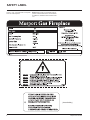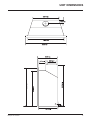
1
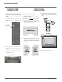
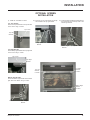
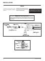
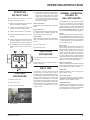
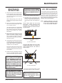
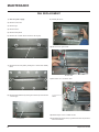
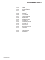
Manual
Owners &
Installation
LISTINGS AND CODE APPROVALS
These gas appliances have been
tested in accordance with AG 103,
NZS 5262 and have been certified
by the Australian Gas Association
for installation and operation as
described in these Installation and
Operating Instructions.
Your unit should be serviced
annually by an authorised
service person.
G51 Surefire
Models: G51-NG
G51-LPG
PLEASE KEEP THESE INSTRUCTIONS
FOR FUTURE REFERENCE
WARNING:
Improper installation, adjustment,
alteration, service or maintenance can
cause injury or property damage. Refer to
this manual. For assistance or additional
information consult an authorised installer,
service agency or the gas supplier.
FOR YOUR SAFETY
Do not store or use gasoline or other
flammable vapours and liquids in the vicinity
of this or any other appliance.
Installation and service must be performed
by an authorised installer, service agency or
the gas supplier.
Australia
P.O. Box 533
Braeside, Victoria
918-257
3195
FOR YOUR SAFETY
What to do if you smell gas:
Do not try to light any appliance
Do not touch any electrical
switch: do not use any
phone in your building.
Immediately call your gas
supplier from a neighbour's
phone. Follow the gas supplier's instructions.
If you cannot reach your
gas supplier, call the fire
department.
New Zealand
1-37 Mt Wellington Hwy.Panmure,
P.O. Box 14349
Auckland 6.
02/02/04
TO THE NEW OWNER:
Congratulations!
You are the owner of a state-of-the-art Gas Stove by FPI FIREPLACE PRODUCTS INTERNATIONAL LTD.
The G51 has been designed to provide you with all the warmth and charm of a wood fireplace at the flick of
a switch.
The G51 has been approved by the Australian Gas Association for both safety and efficiency. As it also bears
our own mark, it promises to provide you with economy, comfort and security for many trouble free years to
follow. Please take a moment now to acquaint yourself with these instructions and the many features of your
Masport Fireplace.
2
Masport G51 Surefire
TABLE OF CONTENTS
Safety Label
Safety Label ............................................................... 4
Installation
Unit Dimensions ......................................................... 5
Important Message .................................................... 6
For Your Safety .......................................................... 6
Gas Pipe Testing ....................................................... 6
Before You Start ........................................................ 6
Installation Checklist .................................................. 6
Materials Required ..................................................... 6
Minimum Fireplace Dimensions ................................. 7
Minimum Clearances to Combustibles ....................... 7
Gas Connection ......................................................... 7
Flueing ..................................................................... 8
Gas Pressure Test ..................................................... 8
Test for Flue Spillage ................................................. 8
Gas Aeration System ................................................. 8
Installation of Flue Gather .......................................... 8
Valve Tray Installation ................................................ 9
Burner Installation ..................................................... 10
Log Set Installation ................................................... 11
Finishing Trim Installation .......................................... 14
Brick Panel Installation .............................................. 14
Screen Installation (Optional) .................................... 15
Wiring .................................................................... 16
Masport G51 Surefire
Operating Instructions
Operating Instructions ............................................... 17
Lighting Procedure .................................................... 17
Shutdown Procedure ................................................. 17
First Fire ................................................................... 17
Normal Operating Sounds of
Gas Appliances .................................................. 17
Lighting Plate Instructions ......................................... 18
Maintenance
Maintenance Instructions .......................................... 19
Log Replacement ...................................................... 19
Fan Replacement ...................................................... 20
Replacement Parts List ............................................. 21
Warranty
Warranty ................................................................... 23
3
SAFETY LABEL
This is a copy of the label that accompanies
each G51 Gas Fireplace.
NOTE: Masport units are constantly being improved. Check the label on the unit and if there
is a difference, the label on the unit is the correct
one.
(Australia Only)
4
Masport G51 Surefire
UNIT DIMENSIONS
Masport G51 Surefire
5
INSTALLATION
IMPORTANT:
SAVE THESE
INSTRUCTIONS
The Masport Gas Fireplace must be installed in
accordance with these instructions. Carefully
read all the instructions in this manual first.
Note: Failure to follow these instructions
could cause a malfunction of the
heater which could result in death,
serious bodily injury, and/or property damage. Failure to follow these
instructions may also void your
fire insurance and/or warranty.
FOR YOUR SAFETY
This appliance requires air for proper combustion. Always provide adequate combustion
and ventilation air. Follow instructions and information in the current AG 601, NZS 5261 or
local codes. Consult the "authority having
jurisdiction" to determine the need for a permit
prior to starting the installation.
GAS PIPE TESTING
The appliance must be isolated from the gas
supply piping system by closing its individual
manual shutoff valve during any pressure
testing of the gas supply piping system at test
pressures equal to or less than 3.45 kPa.
Specifications:
Fuel: NG or LPG
Electrical: 240 volt 50 hz system
Fan/Blower: 2-speed, 127 CFM
Log Sets: Ceramic fibre
BEFORE YOU START
Installation is to be carried out ONLY by an
authorised person.
1) The appliance shall be installed in accordance with the manufacturer's installation
instructions, local gas fitting regulations,
municipal building codes, water supply regulations, electrical wiring regulations, with
AG 601 (AGA gas installation code) NZS
5261 (New Zealand).
2) Installation and repair should be done
ONLY by an authorised person.
3) The appliance should be inspected before
use and at least annually by an authorised
service person. More frequent cleaning
may be required due to excessive lint from
carpeting, bedding material, etc. It is imperative that control compartments, burners
and circulating air passageways of the
appliance be kept clean and free from
excessive lint from carpeting.
4) See general construction and assembly
instructions. This appliance may only be
installed in a flued, non-combustible fireplace. The appliance and flue should be
enclosed when installed or passing through
a living area, where children may come in
contact with it. For combustible enclosure use zero clearance Kit # 390-900.
5) Always connect this space heater to a
chimney and flue to the outside of the
building envelope. Never flue to another
room. Make sure that the flue is properly
sized and is of adequate height to provide
the proper draft.
INSTALLATION
CHECKLIST
The Masport Gas Insert is installed as listed
below.
1) Unit Location - check Clearances to Combustibles on page 7.
2) Make the gas connections, see page 7.
3) Install flue gather to unit, see page 8.
4) Install flue pipe to gather collar.
5) Install valve tray and burner, see pages 910.
5) Test gas pressure, page 8. Check aeration,
page 8.
6) Test for flue spillage, page 8.
7) Install the optional brick panels. See page
14.
8) Install the log set. See page 11.
9) Final check: Before leaving this unit with
the customer, the installer must ensure that
the appliance is firing correctly. This includes:
a) Clocking the appliance to ensure the
correct firing rate.
b) Adjusting the primary air, if required, to
ensure that the flame does not carbon.
c) Ensuring that the appliance is flueing
correctly.
6) Inspect the flueing system annually for
blockage and any signs of deterioration.
7) To prevent injury, do not allow anyone who
is unfamiliar with the operation to use the
fireplace.
MATERIALS REQUIRED
No electric power supply is required for the gas
control to operate. A 240 Volt AC power cord
is hooked up to the fan switch and blower. Plug
3 wire cord into a suitable receptacle. Do not
cut the ground terminal off under any circumstances.
When connected with 240 volts, the appliance
must be electrically grounded in accordance
with local codes.
6
Masport G51 Surefire
INSTALLATION
MINIMUM FIREPLACE
DIMENSIONS
The minimum fireplace dimensions for the
Masport gas space heater are shown in the
following diagrams:
MINIMUM
CLEARANCES TO
COMBUSTIBLES
The minimum fireplace clearances for the
Masport gas space heater are shown in the
following diagrams:
From Unit
Sides
Ceiling
Mantle
Floor
A
B
C
H
305 mm
914 mm
318mm
100mm
Min. Alcove Width
Max. Alcove Depth
K 1435 mm
L 915 mm
Mantle
D 305mm
GAS CONNECTION
GAS CONNECTION WARNING:
Only persons licensed to work with
gas piping may make the necessary
gas connections to this appliance.
1) If the appliance is to be installed into an
existing chimney system, thoroughly clean
the masonry or factory built fireplace.
2) The gas line should be rigid pipe. Copper
may also be used if approved by AG 601.
3) Locate the center point where the flue will
pass through the chimney above the appliance. Move the appliance into the exact
location where it is to be installed. Ensure
that the Insert is level.
SPECIFICATIONS
NG
INJECTOR
NOTE: A non-combustible mantel may be
installed at a lower height if the
framing is made of metal studs
covered with a non-combustible
board.
#29
SIZE
3.45mm
INPUT
Min. 25 mj/h
RATING
Max. 50 mj/h
MANIFOLD
PRESSURE Max. 0.79 kPa
Masport G51 Surefire
7
INSTALLATION
FLUEING
THE APPLIANCE MUST NOT BE CONNECTED
TO A CHIMNEY FLUE SERVING A SEPARATE
SOLID FUEL BURNING APPLIANCE.
This appliance is designed to attach to a 200 mm
diameter type B-Vent or listed gas fuel type vent
liner running the full length of the chimney. A
minimum flue height of 3.6 m. is recommended.
TEST FOR FLUE
SPILLAGE
GAS AERATION
SYSTEM
A "spillage" test must be made before
the installed unit is left with the customer. Follow the procedure below:
The aeration adjustment rod is attached to the
air shutter which is located just above the
orifice bracket. The rod is used to adjust the
aeration on the main burner without having to
take the appliance apart.
1) Start all exhaust fans in the home and then
close all external doors and windows in the
house.
Periodically check that the flue is unrestricted
and an adequate draft is present when the unit
is in operation.
2) Light the unit and set controls to maximum.
Turn fan off.
Before installing flue system ensure that the
damper plate is open and secure to prevent the
damper plate from falling down and crushing
the liner.
3) After five minutes, test that there is a “pull”
on the flue by placing a smoke match,
cigarette or similar device which gives off
smoke, in position as shown.
Install to AG 601 (Australia), NZS 5261 (New
Zealand).
Light a match close to centre. Check
if smoke is drawn inside flue.
The burner aeration is factory set but may need
adjusting due to either the local gas supply, air
supply or altitude. This adjustment is performed
by the installer. (Pull the rod for a more yellow
flame, or push the rod to make the flame bluer.)
NG:
5 mm open
Note: Any damage due to carboning resulting from improperly setting
the aeration controls is NOT covered under warranty.
Combustion and Ventilation Air
WARNING: This appliance needs fresh
air for safe operation and must be installed with provisions for adequate
combustion and ventilation air available
to the room in which it is to be operating.
INSTALLATION OF
FLUE GATHER
1) Line up flue gather with the holes on the
firebox.
Air for combustion is drawn in through the front
of the unit, therefore, the front of the unit must
be kept clear of any obstructions.
2) Secure in place with 16 screws.
GAS PRESSURE TEST
The unit is preset to give the correct gas input
at the specified manifold pressures shown on
the label. The maximum gas manifold pressure
is:
NG
0.79 kPa
The pressure check should be carried out with
the unit burning and the setting should be within
the limits specified.
Diagram 1
Outlet Pressure
Test Point
8
Masport G51 Surefire
INSTALLATION
VALVE TRAY
INSTALLATION
1) Line up valve tray with 4 holes in firebox and secure with screws.
3) Place the valve shield over the valve and secure with screw.
Valve Shield
Screw
4) Install the valve cover by aligning it with the 3 holes in the firebox
and secure with screws.
Secure valve tray
with 4 screws.
2) Connect the unit to the gas line using a flex pipe.
Valve Cover
Flex Pipe
Gas Line
Masport G51 Surefire
9
INSTALLATION
BURNER
INSTALLATION
1) Fit burner tube into orifice.
Burner Tube
Orifice
Secure burner to
valve tray.
2) Secure burner to the valve tray using one screw.
3) Close valve cover.
Screw location
in valve tray.
Valve Cover
10
Masport G51 Surefire
INSTALLATION
LOG SET
INSTALLATION
Carefully read the instructions below and refer to the diagrams.
If logs are broken do not use the unit until they are replaced.
Broken logs can interfere with the pilot operation.
The gas log kit (Part #390-930) contains the following pieces:
a)
b)
c)
d)
e)
f)
g)
i)
02-55
02-52
02-51
02-50
02-95
02-96
02-97
Middle Left Log
Middle Right Log
Front Bottom Log
Front Left Log
Rear Log
Center Left Log
Center Right Log
Embers Lava
02-95
902-237
902-240
902-241
902-242
902-375
902-376
902-377
902-156
3) Place Log 02-51 on the front right side of the burner. Push the back
of the log against the 2 brackets with the notch on the bottom right
side of the log fitting onto the side of the grate.
The "02" reference numbers (i.e. 02-55) are
moulded into the rear/bottom of each log.
02-95
02-95
02-52
02-55
Brackets
02-97
02-50
02-96
02-51
02-51
1) Carefully remove the logs from the box and unwrap them. The logs are
fragile, handle with care - do not force into position.
Rest notch on right
side of grate.
2) Place Log 02-95 on the 2 rear log support pins with the flat side of the
log to the back.
4) Position Log 02-96 across the cutouts in Logs 02-95 and 02-51 with
the notch on the bottom left side of the log fitting into the 2nd grate
tab.
02-95
02-95
02-96
02-51
Pins
Cutouts
Masport G51 Surefire
11
INSTALLATION
02-95
02-96
02-51
02-50
Fit notch into 2nd grate tab.
5) Place the bottom left front edge of Log 02-55 against the rear bracket
on the burner tray and rest the log on the cutout in Log 02-96.
Fit notch onto left side of grate.
7) Position Log 02-97 across the cutouts in Logs 02-51 and 02-96.
Fit the notch in the bottom right end of the log against the 5th grate
tab.
02-55
02-96
Rear Bracket
Cutout
02-97
02-96
02-51
Cutouts
02-55
02-96
02-97
6) Sit Log 02-50 on the front left side of the burner. Push the back of the
log against the 2 front brackets with the notch on the bottom of the log
fitting onto the side of the grate.
Fit notch into 5th grate tab.
8) Place Log 02-52 behind Logs 02-51 and 02-97 and rest the top end
of the log on the cutout in Log 02-97. The bottom right end of the log
goes behind the bracket at the back of the grate.
02-50
02-97
Bracket towards
back of grate.
Photo shows rear of
grate.
Log 02-51 was removed
to show bracket.
Front Brackets
12
Masport G51 Surefire
INSTALLATION
9) Place the embers lava on the front of the burner tray as shown in
the circled areas in the picture below.
02-52
02-97
Embers Lava
Ensure not to block the burner ports.
Cutout
Bracket
Log 02-51 was removed to show
placement of Log 02-52.
10) Test fire to ensure proper light off (make sure flame flows smoothly
from one end of burner to the other). If there is any flame hesitation,
check that area for any blockage of the burner ports.
11) Install screen door as per instructions in this manual.
02-52
02-95
02-50
Masport G51 Surefire
02-55
02-96
02-51
02-97
13
INSTALLATION
FINISHING TRIM
INSTALLATION
1) Fit the left side finishing trim onto the firebox
by sliding the cut-outs on the finishing trim
through the screws on the side of the
firebox.
Once trim is fitted in place, secure by
tightening the 2 screws. Repeat for right
side.
BRICK PANEL
INSTALLATION
1) Remove screen door, if used.
2) Carefully unwrap the brick panels from the
protective wrapping.
5) Install the brick retaining clips, one on each
side to secure the side brick panels in
place.
NOTE: The logs must not be in the unit.
3) Insert the back brick panel first by carefully
slipping it between the back wall of the
firebox and rear log brackets.
Left Side
Finishing
Trim
4) Slide the side panels in from the front and
push them flat up against the wall. Be very
careful not to scratch them on the firebox
hardware.
2) Fit top finishing trim onto firebox. Ensure
cut-outs in trim lineup with screws on
firebox.
6) Re-install screen door, if used.
Secure in place by tightening the 3 screws
once fitted in place.
Top Finishing Trim
14
Masport G51 Surefire
INSTALLATION
OPTIONAL SCREEN
INSTALLATION
1) Install the 3 brackets as shown.
2) Fit the pin on top of the screen into the pin
hole located in the top right bracket.
Top Left Bracket:
Secure the top left bracket to the top left side
of the louver using 2 screws.
3) Pull up the spring loaded pin at the bottom of
the screen and rest it in the pin hole of the
bottom right bracket.
Top Louver
Top Left
Bracket
Top Right
Bracket
Pin in Screen
Bottom Right
Bracket
Spring Loaded Pin
Top Right Bracket:
Secure the top right bracket to the top right side
of the louver using 2 screws.
Top Louver
Top Right
Bracket
Top Left
Bracket
Location
Top Right
Bracket
Location
Bottom Right Bracket:
Secure the bottom right bracket to the bottom
right side of the firebox using 2 screws.
Bottom Right
Bracket
Location
Firebox
Masport G51 Surefire
Bottom Right
Bracket
15
INSTALLATION
WIRING
This heater does not require a 240V A.C. supply
for the gas control to operate. A 240V A.C.
power supply is needed for the fan/blower
operation.
Caution: Ensure that the wires do
not touch any hot surfaces and are
away from sharp edges.
CAUTION: Label all wires prior to
disconnection when servicing controls. Wiring errors can cause improper and dangerous operation.
WARNING: Electrical Grounding Instructions
This appliance is equipped with a three pronged (grounding) plug for your
protection against shock hazard and should be plugged directly into a properly
grounded three-prong receptacle. Do not cut or remove the grounding prong
from this plug.
16
Masport G51 Surefire
OPERATING INSTRUCTIONS
OPERATING
INSTRUCTIONS
Before operating this appliance, proceed
through the following check list.
1) Read and understand these Instructions
before operating this appliance.
2) Check to see that all wiring is correct and
enclosed to prevent possible shock.
3) Check to ensure there are no gas leaks.
4) Verify that all flueing and the cap is unobstructed.
5) Verify log placement. If the pilot cannot be
seen when lighting the unit - the logs or the
embers have been incorrectly positioned.
6) The unit should never be turned off and on
again without a minimum wait of 60 seconds.
4) Fully press the ignition button and ignite the
pilot burner by continously depressing the
piezo ignitor. Once the pilot has lit, continue
holding in the ignition button for approximately 10 seconds to ensure the pilot stays
on. If it goes out, wait 1 minute and repeat
the ignition operations.
Normal Operation:
Depress the ignition button again to ignite the
burner.
Flame Selection:
Press the flame button for the flame adjustment.
For minimum flame, depress the button. For
maximum flame, release the button.
Pilot Position:
Depress the ignition button to turn off the burner
flame. The indicator should show the ignition
symbol.
5) Close valve cover.
6) Install screen door.
SHUTDOWN
PROCEDURE
Turn OFF the shut off valve to shut down the pilot
and burner.
Always install screen door during operation to
reduce risk of injury.
FIRST FIRE
LIGHTING
PROCEDURE
1) Remove screen door.
2) Open valve cover.
3) Turn ON the shut off valve.
The first fire in your stove is part of the paint
curing process. To ensure that the paint is
properly cured, it is recommended that you burn
your fireplace for at least four (4) hours the first
time you use it with the fan on. When first
operated, the unit will release an odour caused
by the curing of the paint, the burning off of any
oils remaining from manufacturing. Smoke detectors in the house may go off at this time. Open
a few windows to ventilate the room for a
couple of hours.
NORMAL OPERATING
SOUNDS OF
GAS APPLIANCES
It is possible that you will hear some sounds
from your gas appliance. This is perfectly
normal due to the fact that there are various
gauges and types of steel used within your
appliance. Listed below are some examples. All
are normal operating sounds and should
not be considered as defects in your appliance.
Blower:
Masport gas appliances use high tech blowers
to push heated air farther into the room. It is not
unusual for the fan to make a "whirring" sound
when ON. This sound will increase or decrease
in volume depending on the speed setting of
your fan speed control.
Burner Tray:
The burner tray is positioned directly under the
burner tube(s) and logs and is made of a
different gauge material from the rest of the
firebox and body. Therefore, the varying thicknesses of steel will expand and contract at
slightly different rates which can cause "ticking" and "cracking" sounds. You should also be
aware that as there are temperature changes
within the unit these sounds will likely re-occur.
Again, this is normal for steel fireboxes.
Blower Thermodisc:
When this thermally activated switch turns ON
it will create a small "clicking" sound. This is the
switch contacts closing and is normal.
Pilot Flame:
While the pilot flame is on it can make a very
slight "whisper" sound.
Gas Control Valve:
As the gas control valve turns ON and OFF, a
dull clicking sound may be audible, this is normal
operation of a gas regulator or valve.
Unit Body/Firebox:
Different types and thicknesses of steel will
expand and contract at different rates resulting
in some "cracking" and "ticking" sounds will be
heard throughout the cycling process.
Shut off Valve
Masport G51 Surefire
17
OPERATING INSTRUCTIONS
COPY OF LIGHTING PLATE INSTRUCTIONS
FOR YOUR SAFETY READ
BEFORE LIGHTING
This appliance must be installed in accordance with local
codes, if any; if not, follow current CAN1-B149/ANSI
Z223.1 Australia: AG 601/New Zealand: NZS 5261.
WARNING: If you do not follow these instructions exactly,
a fire or explosion may result causing property damage,
personal injury or loss of life. Improper installation,
adjustment, alteration, service or maintenance can cause
injury or property damage. Refer to the owner’s information manual provided with this appliance. For assistance
or additional information consult a qualified installer,
service agency or gas supplier.
A) This appliance has a pilot which must be lighted by
hand. When lighting the pilot, follow these instructions exactly.
B) BEFORE LIGHTING smell all around the appliance
area for gas. Be sure to smell next to the floor
because some gas is heavier than air and will
settle on the floor.
WHAT TO DO IF YOU SMELL GAS
Do not try to light any appliance
Do not touch any electric switch, do not use any
phone in your building
Immediately call your gas supplier from a neighbours phone. Follow the gas supplier’s instructions.
If you cannot reach your gas supplier, call the fire
department.
C) Use only your hand to push in or turn the gas
control knob. Never use tools. If the knob will not
push in or turn by hand, don’t try to repair it, call a
qualified Service technician. Force or attempted
repair may result in a fire or explosion.
D) Do not use this appliance if any part has been
under water. Immediately call a qualified service
technician to inspect the appliance and to replace
any part of the control system and any gas control
which has been under water.
This appliance needs fresh air for safe operation and
must be installed so there are provisions for adequate combustion and ventilation air.
LIGHTING INSTRUCTIONS
STOP! Read the safety information above on this label.
1) Remove screen door, if used.
2) Open valve cover.
3) Turn ON the shut off valve.
4) Fully press the ignition button and ignite the
pilot burner by continously depressing the
peizo ignitor. Once the pilot has lit, continue
holding in the ignition button for approximately
10 seconds to ensure the pilot stays on. If it
goes out, wait 1 minute and repeat the ignition
operations.
Normal Operation:
Press and release the ignition button again to ignite the burner.
Flame Selection:
Press the flame button for the flame adjustment. For minumum
flame, depress the button. For maximum flame, release the
button.
Pilot Position:
Press and release the ignition button to turn off the burner
flame. The indicator should show the ignition symbol.
5) Close valve cover.
6) Install screen door, if used.
TO TURN OFF GAS APPLIANCE
Turn OFF the shut off valve to shut down the pilot and
burner.
Always install screen door during operation to reduce
risk of injury.
You may shut off the pilot during prolonged
non use periods to conserve fuel.
918-249
DO NOT REMOVE THIS INSTRUCTION PLATE
CAUTION: Hot while in operation. Do not touch. Severe
Burns may result. Due to high surface temperatures
keep children, clothing and furniture, gasoline and
other liquids having fammable vapors away. Keep
burner and control compartment clean. See installation and operating instructions accompanying appliance.
ANY SERVICING OR REPAIRS
SHOULD BE CARRIED OUT ONLY BY AN
AUTHORISED PERSON.
18
Masport G51 Surefire
MAINTENANCE
MAINTENANCE
INSTRUCTIONS
1) Always turn the gas valve off before cleaning. For relighting, refer to lighting instructions. Keep the burner and control compartment clean by brushing and vacuuming at
least once a year.
When cleaning the logs, use a clean soft
paint brush as the logs are fragile and easily
damaged.
2) Clean (never when unit is hot) appliance,
door and louvres with a damp cloth. Never
use an abrasive cleaner.
The heater is finished in a heat resistant
paint and should only be refinished with
heat resistant paint (not with wall paint).
Masport uses StoveBrite Paint - Metallic
Black #6309.
CLOTHING OR OTHER FLAMMABLE MATERIAL SHOULD NOT BE
PLACED ON OR NEAR THE APPLIANCE.
6) Verify proper operation after servicing.
7) Periodically check the pilot flames, there
should be two strong blue flames approx.
3/4" long - 1 flame to the front burner, and
1 to the thermocouple. See diagrams below.
Correct flame pattern has two strong
blue flames: 1 flowing around the thermocouple and 1 reaching towards the
rear burner (it does not have to be touching the burner).
LOG REPLACEMENT
The unit should never be used with broken logs.
Turn off the gas valve and allow the unit to cool,
carefully remove the logs. The pilot light generates enough heat to burn someone. If for any
reason a log should need replacement, you
must use the proper replacement log. The position of these logs must be as shown in the
diagrams under Log Set Installation.
NOTE: Improper positioning of logs may
create carbon build-up and will alter the unit’s performance which
is not covered under warranty.
3) Make a periodic check of burner for proper
position and condition. Visually check the
flame of the burner periodically, making
sure the flames are steady; not lifting or
floating. If there is a problem, call an authorised service person.
4) The appliance and flueing system must be
inspected before use, and at least annually, by an authorised field service person, to
ensure that the flow of combustion and
ventilation air is not obstructed.
During the annual service call, the burners
should be removed from the burner tray
and cleaned. Replace the embers but do not
block the pilot.
Top View of pilot flame
Incorrect flame pattern will have small,
probably yellow flames, not coming into
proper contact with the rear burner or
thermocouple.
5) Keep the area near the appliance clear and
free from combustible materials, gasoline
and other flammable vapours and liquids.
WARNING: CHILDREN AND
ADULTS SHOULD BE ALERTED
TO THE HAZARDS OF HIGH SURFACE TEMPERATURE AND
SHOULD STAY AWAY TO AVOID
BURNS OR CLOTHING IGNITION.
YOUNG CHILDREN SHOULD BE
CAREFULLY SUPERVISED WHEN
THEY ARE IN THE SAME ROOM
AS THE APPLIANCE.
Top View of pilot flame
If you have an incorrect flame pattern, contact
your Masport dealer for further instructions.
CAUTION: ANY SAFETY SCREEN
OR GUARD REMOVED FOR SERVICING AN APPLIANCE MUST BE
REPLACED PRIOR TO OPERATING THE APPLIANCE.
Masport G51 Surefire
WARNING
Do not spray aerosols in the
vicinity of this appliance while in
operation.
19
MAINTENANCE
FAN REPLACEMENT
1) Shut off power supply.
9) Partially lift out fan.
2) Remove screen door.
3) Remove logs.
4) Remove burner.
5) Remove brick panels.
6) Remove the 2 screws which secure the rear log tray.
10) Disconnect the ground wire.
Rear Log Tray
7) Remove the fan cover plate by undoing the 11 screws and carefully
lift out.
Ground Wire
11) Disconnect the 3 connector wires.
8) Remove the fan deflector by undoing the 3 screws (2 on the left and
1 on the right).
Connector
Wires
12) Reverse steps 10 to 6 to install new fan.
Fan Deflector
20
13) Re-install brick panels, burner, logs and screen door as per instructions in this manual.
Masport G51 Surefire
REPLACEMENT PARTS
Part #
390-033
390-510/P
390-511/P
390-525
511-031
560-519/P
390-000
390-930
904-258
904-658
904-777
904-652
908-227
910-006
910-053
910-054
910-090
910-091
910-092
910-093
910-094
910-095
910-140
910-169/P
910-190
910-692
910-714
910-731
910-900
918-257
918-249
948-218
Masport G51 Surefire
Description
Hood Pilot
Valve Assembly - NG
Valve Assembly - LPG
Burner Assembly - NG/LPG
Clip Brick
Fan Assembly
Grate Assembly
Log Set
Magnet Ceramic
Inlet Flex Line Gas E61
Orifice #29 NG
Orifice #46 LPG
Label Blower Emerald Insert
Terminal Block 3 Pole
Regulator NG RV20LSF-33 W/PF10
Regulator LPG
Valve NG Simplosit 0.500.017
Valve Simplosit LPG
Pilot Assembly Oxypilot NG 9058
Pilot Assembly Oxypilot LPG
Cable Ignition
Knob Push/Pull 10-32
Switch 3 Way Carling
Fan 240V Transflow 2 Speed
Peizo Ignitor Push Button Black
Wire Fan to Power Cord Ground
Power Cord 240V
Wire Fan to Terminal Block
Wire Fan to Switch
Manual
Lighting Instruction Decal
Logo Plate Masport
21
NOTES
_____________________________________________________________________________________
____________________________________________________________
__________________________________________________________
____________________________________________________________
_______________________________________________________
_____________________________________________________
__________________________________________________________
_________________________________________________________
_________________________________________________________
______________________________________________________
______________________________________________________
_______________________________________________________________
___________________________________________________________
__________________________________________________________
____________________________________________________________
____________________________________________________________
____________________________________________________________
_____________________________________________________________
__________________________________________________________
__________________________________________________________
_____________________________________________________
________________________________________________________
_________________________________________________________
_________________________________________________________
22
Masport G51 Surefire
WARRANTY
THE MASPORT EXPRESS WARRANTY
All new Masport Gas appliances are warranted, subject to the
following conditions, to be free from defects in material or
workmanship under normal use. The Express Warranty on all
parts, including firebox components but excluding fans, flues
and flue accessories is two years from date of original
purchase as well as labour costs involved in the repair or
replacement. The Express Warranty on fans, flues and accessories is for a period of twelve months from date of original
purchase and includes labour costs involved in the repair or
replacement.
This Express Warranty Does Not Cover:
1. Defects, malfunctions or failures caused by incorrect installation, normal wear and tear, misuse, neglect, accidental
damage or failure to follow the fuel selection, product operating and maintenance instructions, or resulting from installations, repairs or modifications to the equipment carried out
by unauthorised persons.
2. Defects, malfunctions or failures caused by an act or omission of other persons after the product has left Masport's
control.
This Express Warranty applies only with respect to defects in
material and workmanship under normal and proper use of
the NEW UNIT in its unmodified condition. Masport's obligation under this Express Warranty is limited to the repair or
replacement, at its option, by an approved Masport Gas
Service Agent (Retailer) of any part found to be defective in
material or workmanship.
3. The costs of collection and delivery of the equipment.
Labour costs involved in the repair or replacement are also
covered under this Express Warranty as per the time condition
outlined.
If an approved Masport Gas Service Agent is requested to
attend on a service call that is not covered under this Express
Warranty, a call out charge may be applicable, regardless of
whether a repair is carried out or not.
Masport can accept no obligation whatsoever for any incidental, consequential or special damages or expenses resulting
from any product defect. This Express Warranty applies from
the date of original purchase, applies to the original purchaser, and is not transferable. The decision to repair or replace
defective components will be made by Masport or its agent
and actioned by an approved Masport Service Agent.
4. The cost of labour or materials as a consequence of faulty
installation of gas supply line, flue, burner or log settings, or
non-compliance with local codes.
The Express Warranty is not intended to exclude any rights the
purchaser may have under the laws of the place, state, or
country of purchase. Nothing in this Express Warranty limits
or restricts any other statutory right or remedy available to the
purchaser.
How You Obtain Warranty Service:
Provide proof of the date of purchase. Should the need for a
warranty claim arise reasonable proof of the purchase date is
required therefore you should retain your sales receipt. Where
flueless appliances are not permanently installed, they should
be returned to a Service Agent for evaluation.
Make the faulty part(s) available for inspection by Masport and/
or its agents so that the validity of the claim can be established
by them.
Australia Distributor:
New Zealand:
Masport Pty Limited
P.O. Box 533
Braeside Victoria 3195
Masport Limited
P.O. Box 14-349
Panmure
Auckland 6
For your own records, please complete the following:
Model: ________________________________________ Serial Number: ____________________________
Retailer: ________________________________________________________________________________
______________________________________________________________________________________
Purchase Date: _______________________________
Masport G51 Surefire
23
© Copyright 2004, FPI Fireplace Products International Ltd. All rights reserved.
Printed in Canada