1
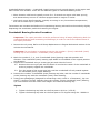
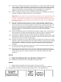
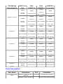
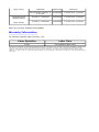
#99-06-01-003: Engine Bearing Knock Noise (Resuppport Crankshaft, Select-fit Rod Bearings) - (Mar
29, 1999)
Subject:
Engine Bearing Knock Noise, (Re-support Crankshaft,
Select-fit Undersize Connecting Rod Bearings)
Models:
1999 Cadillac Escalade
1996-99 Chevrolet and GMC C/K, G, P Models
with 5.0L or 5.7L Engine (VINs M, R - RPOs L30, L31)
Important
GM Canada Dealers require prior DSM authorization to apply this bulletin.
Condition
Some customers may comment about an engine "knocking" noise.
Cause
A condition may exist in some engines where, the crankshaft is NOT being evenly supported by
all five crankshaft bearing inserts. In these engines, the number 1, 2, 3, and 4 crankshaft
bearing inserts are supporting the crankshaft, and the number 5 crankshaft journal (rear) has
excessive clearance relative to the number 5 crankshaft (main) bearing cap insert. In this
condition, the crankshaft flexes under load, and pounds on the lower number 5 crankshaft
(main) bearing insert creating the knocking sound. The engines were originally built with
0.0006 in. undersize crankshaft (main) bearing inserts in the number 2, 3, and 4 crankshaft
(main) bearing locations and 0.001 in. undersize insert in the number 5 crankshaft (main)
bearing location. The service procedure listed below addresses the above condition by lowering
the crankshaft at the number 2, 3, and 4 crankshaft (main) bearing positions (increased
crankshaft (main) bearing size of the lower crankshaft (main) bearing inserts) and raising the
number 5 lower crankshaft (main) bearing insert (undersized insert) in order to properly
contact the number 5 crankshaft journal surface.
These engines may also exhibit a connecting rod knocking sound. In these engines, the
connecting rod knocking sound is caused by excessive connecting rod bearing clearance.
A customer concern vehicle may exhibit one or both of the above stated conditions.
Correction
Follow strategy-based diagnostics for engine noise listed in the front of Section 6 of the Service
Manual.
Some additional key points:
Rod Bearing Knock -- Occurs on initial engine start-up, and can also be heard as high as 1,5001,800 RPM. Rod bearing knock typically diminishes or completely goes away when the engine
reaches normal operating temperature.
Crankshaft Bearing Knock -- Crankshaft (main) bearing knock sounds deeper in the engine and
also sounds more muffled. There are two different types of crankshaft bearing knock.
• Short duration cold knock typically occurs for 1-5 seconds on engine cold start-up only,
and almost always occurs on vehicles equipped with an engine oil cooler.
• Hot knock occurs less frequently, typically occurring in very hot ambient temperatures,
and can be heard up to 2,000 RPM.
Technicians can increase the likelihood of reproducing bearing induced knock sounds by slightly
depressing the accelerator pedal while starting the engine.
Crankshaft Bearing Service Procedure
Important: The repair procedure must be performed using all steps (addressing both the
crankshaft bearings and connecting rod bearings) in order to ensure the effectiveness of
the repair procedure.
1. Remove the oil pump. Refer to Oil Pump Replacement in Engine Mechanical section of the
Vehicle Service Manual.
Important: Do not loosen or attempt to service the number 1 (front) crankshaft (main)
bearing cap or the number 1 crankshaft (main) bearings.
2. Mark the number 2, 3, 4, and 5 crankshaft (main) bearing caps with position and
direction. The crankshaft (main) bearing caps MUST be reinstalled in the original position
and direction.
3. Support the crankshaft using a screw type jack and a block of wood.
3.1. Position the screw type jack and the block of wood at the center of the crankshaft in
order to properly support the crankshaft.
3.2. Turn the screw of the screw type jack until the crankshaft is firmly seated against
the crankshaft (main) upper bearings.
4. Remove the number 5 crankshaft (main) bearing cap bolts, and the number 5 crankshaft
(main) bearing cap with the crankshaft (main) lower bearing.
5. Using green plastigauge (designed for measuring 0.001-0.003 in. of clearance), lay two
pieces, 2 inches in length, laterally along the number 5 lower crankshaft (main) bearing,
1/4 inch inboard from the insert outer edges. Re-install the bearing cap.
Tighten
1. Tighten the bearing cap bolts on the first pass to 20 N·m (15 lb ft).
2. Tighten the bearing cap bolts on the final pass to 73 degrees using the J 36660-A.
6. Remove the number 5 cap and measure the plastigauge using the inch scale. All 1996-99
5.0L (L30) and 5.7L (L31) engines were built with 0.001 in. undersized number 5
crankshaft bearing inserts.
7. If the measurement is:
• Less than 0.0020 in. -- Go To Step 8
• 0.0020 in. or greater but less than 0.0025 in. -- Go To Step 9
• 0.0025 in. or greater but less than 0.0030 in. -- Go To Step 10
• 0.0030 in. or greater -- Go To Step 11
8. Less than 0.0020 in.
8.1. Retain production 0.001 in. undersize upper and lower bearing inserts at the
number 5 crankshaft bearing position.
8.2. Clean any and all plastigauge material and residue from the bearing inserts.
8.3. Liberally coat bearing inserts with clean engine oil and reinstall crankshaft bearing
caps and bolts.
8.4. Reinstall crankshaft bearing cap, bolts and studs to the engine block, making sure
that the cap, bolts, and studs retain their original position and orientation.
Tighten
1. Tighten the crankshaft bearing cap bolts and studs on the first pass to 20 N·m
(15 lb ft).
2. Tighten the crankshaft bearing cap bolts on the final pass to 73 degrees using the
J 36660-A.
8.5. Remove Screwjack used for crankshaft support.
8.6. Go to Step 12 Crankshaft (main) Bearing Service for Locations Number 2, 3, and 4.
9. 0.0020 in. or greater but less than 0.0025 in.
9.1. Retain upper bearing shell (number 5 main bearing - production 0.001 in.
undersized).
9.2. Remove number 5 lower main bearing shell from the cap and discard.
9.3. Install 0.002 in. undersize bearing insert (P/N 12329792) in the number 5 cap,
LOWER HALF ONLY.
9.4. Apply a liberal coating of clean engine oil to the bearing surface.
9.5. Reinstall crankshaft bearing cap, bolts and studs to the engine block, making sure
that the caps, bolts, and studs retain their original position and orientation.
Tighten
1. Tighten the crankshaft bearing cap bolts and studs on the first pass to 20 N·m
(15 lb ft).
2. Tighten the crankshaft bearing cap bolts on the final pass to 73 degrees using the
J 36660-A.
9.6. Remove the screw jack used for crankshaft support.
9.7. Go to Step 12 Crankshaft (main) Bearing Service for Locations Number 2, 3, and 4.
10. 0.0025 in. or greater but less than 0.0030 in.
10.1. Lower jack stand from crankshaft, allowing the crankshaft to be supported by the
numbers 1, 2, 3, and 4 crankshaft main bearings.
10.2. Insert J 8080 into the crankshaft number 5 main bearing oil hole and rotate the
crankshaft to turn the upper bearing insert out of the engine block. Discard the
removed upper bearing insert.
10.3. Insert J 8080 into the crankshaft number 5 main bearing oil hole.
10.4. Procure the crankshaft number 5 main bearing 0.0020 in. undersize bearing upper
insert (from kit P/N 12329792), apply clean engine oil to the bearing insert, and
insert the plain end (without the bearing tang) of the bearing shell between the
crankshaft and the notched side of the engine block web.
10.5. Rotate the crankshaft to roll the upper bearing insert into the engine block.
10.6. Remove the J8080 from the crankshaft.
10.7. Remove the number 5 lower main bearing shell from the cap and discard.
10.8. Install 0.002 in. undersize bearing lower insert (from kit P/N 12329792) in the
number 5 cap.
10.9. Apply a liberal coating of clean engine oil to the bearing surface.
10.10. Reinstall crankshaft bearing cap, bolts and studs to the engine block, making
sure that the caps, bolts, and studs retain their original position and orientation.
Tighten
Tighten the crankshaft bearing cap bolts and studs on the first pass to 20 N·m (15 lb ft).
10.11. Thrust the crankshaft rearward in order to set and align the crankshaft thrust
bearings and the crankshaft bearing caps.
10.12. Thrust the crankshaft forward in order to align the rear faces of the crankshaft
thrust bearings.
Tighten
Tighten the crankshaft bearing cap bolts on the final pass to 73 degrees using the
J 36660-A.
10.13. Go to Step 12 Crankshaft (main) Bearing Service for Locations Number 2, 3, and
4.
11. 0.0030 in. or greater
11.1. Retain upper bearing shell (number 5 main bearing - production 0.001 in.
undersized).
11.2. Remove number 5 lower main bearing shell from the cap and discard.
11.3. Install 0.004 in. undersize bearing insert (P/N 12561191) in the number 5 cap,
LOWER HALF ONLY.
11.4. Apply a liberal coating of clean engine oil to the bearing surface, reinstall
crankshaft bearing cap, bolts and studs to the engine block, making sure that the
caps, bolts, and studs retain their original position and orientation.
Tighten
1. Tighten the crankshaft bearing cap bolts and studs on the first pass to 20 N·m
(15 lb ft).
2. Tighten the crankshaft bearing cap bolts on the final pass to 73 degrees using the
J 36660-A.
11.5. Remove the screw jack used for crankshaft support.
11.6. Go to Step 12 Crankshaft (main) Bearing Service for Locations Number 2, 3, and
4.
12. Crankshaft (main) Bearing Service for Locations Number 2, 3, and 4
Important: Do not remove the number 1 (front) main bearing cap.
12.1. Mark and remove the bearing caps from crankshaft bearings number 2, 3, and 4.
12.2. Install new bearing inserts P/N 10120990 (standard size - lower inserts only) to
the numbers 2, 3, and 4 crankshaft bearing caps.
Important: Bearing caps must be installed in the proper location and orientation
or engine damage could result.
12.3. Apply a liberal coating of clean engine oil to the bearing surface, and reinstall the
bearing cap and bolts.
Tighten
1. Tighten the bearing cap bolts on the first pass to 20 N·m (15 lb ft).
2. Final Pass (two bolt main bearing caps) -- Tighten the bearing cap bolts on the final
pass to 73 degrees using the J 36660-A.
3. Final Pass (four bolt main bearing caps) -- Tighten the crankshaft bearing cap
OUTBOARD bolts and studs to 43 degrees using the J 36660-A.
4. Final Pass (four bolt main bearing caps) -- Tighten the crankshaft bearing cap
INNER bolts and studs to 73 degrees using the J 36660-A.
12.4. Go to Step 13 Connecting Rod Bearing Service.
13. Connecting Rod Bearing Service
Important: Do not disassemble connecting rod bearing caps for bearing clearance
measurement. The design of the connecting rods in these engines does not permit
accurate bearing clearance measurements when the connecting rod caps are
disassembled from the connecting rods. Conventional methods of measuring
bearing clearance, such as Plastigauge, cannot accurately be performed on these
engines.GM Powertrain has developed a new, accurate and time-efficient means
for measuring connecting rod bearing clearance without disassembly of the
connecting rods. In early 1999, SPX/Kent-Moore Tool will be releasing a new
essential tool to dealers in the United States to facilitate this new procedure.Until
this new, essential tool is released -Contact: SPX/Kent-Moore Tool at 1 (810) 3452233 who will then arrange for dealers to borrow a special connecting rod bearing
clearance measuring tool and associated instruction sheet and video.Using this
methodology, measure and refit connecting rod bearing inserts in each of the
connecting rods. Use undersize connecting rod bearing inserts (listed in the table
below) to selectively fit each connecting rod bearing for a clearance of 0.0010.002 in.
13.1. Center the connecting rod journal to be worked on in the 6 o'clock position. Using
screw jacks, lock the crankshaft in position as close to the bearing being worked
on as possible. Tighten the screw jack sufficiently to displace the oil film from the
upper main bearings. To avoid damage to the crankshaft, use a cushioning
material, such as a block of wood, between the crankshaft and jack.
13.2. Check rod bearing clearance using a bearing loading and unloading tool and test
indicator capable of measuring 0.0001 inch increments.
Important: A test indicator is required for this procedure, do not substitute a dial
indicator. A dial indicator uses a plunger and will not provide repeatable results.
Likewise, Plastigauge is not effective in this repair and should not be used for this
procedure. To ensure this analysis technique will be accurate, do not disassemble
the rod assembly.
13.3. With the rod bearing to be worked on in the 6 o'clock position, install the test
indicator. Tighten the thumb screw until snug. Install the base bracket to the oil
pan rail and center it so that the handle can move freely in the slot provided. The
link pin on the connecting rod bearing clearance measuring tool should line up
with the centerline of the connecting rod, and have a push/pull action in line with
the connecting rod. This alignment is crucial for accurate and repeatable
measurements.
13.4. Screw the attaching stud of the flexible dial indicator support into a convenient oil
pan rail bolt hole. Position the dial indicator so that the stylus is centered on the
connecting rod cap and lock the flexible dial indicator support into position.
13.5. Using the fine adjustment feature on the flexible dial indicator support (knob near
dial indicator), adjust so that the dial indicator needle has sufficient travel in both
directions to take an accurate measurement.
13.6. Load the connecting rod in the upward direction of piston travel and zero the test
indicator. Load the connecting rod in the reverse direction, and record the reading
off the indicator. Repeat this process 2-3 times, applying consistent pressure in
each direction to ensure the oil film is pushed out of the journal. Record these
readings.
13.7. In order to accurately determine which rod or rods is causing the knock, perform
this procedure on all eight rod assemblies.
13.8. Analyze the measurements from all eight rods. Select bearings that will put the
total clearance for each rod at 0.001-0.002 inch clearance. Install new upper and
lower bearing inserts as required, being sure to lubricate liberally with clean
engine oil.
Tighten
1. Tighten the rod bearing caps on the first pass to 27 N·m (20 lb ft).
2. Tighten the rod bearing caps on the final pass to 55 degrees.
13.9. Reinstall the oil pump to the crankshaft rear bearing cap.
Tighten
1. Tighten the oil pump bolt on the first pass to 20 N·m (15 lb ft).
2. Tighten the oil pump bolt on the final pass to 65 degrees using the J 36660-A.
14. Reassemble as required. Use Service Manual procedure -- Re-install Oil Pan.
Crankshaft
Number 5
(main) Bearing
Clearance (per
Greater
than
0.002 in,
but less
0.0025 in
and greater,
but less
Plastigauge
Measurement
0.002 in or
less
than
0.0025 in
0.0030 in
or greater
UPPER
UPPER
Do Not
Service
than
0.0030 in
UPPER
UPPER
0.002 us
Do Not Service
Do Not Service
P/N 12329792
LOWER
LOWER
LOWER
0.002 us
0.002 us
0.004 us
P/N 12329792
P/N 12329792
P/N 12561191
(use 1/2 kit)
(use 1 kit)
(use 1 kit)
UPPER
UPPER
UPPER
Do Not
Service
Do Not Service
Do Not Service
Do Not Service
LOWER
LOWER
LOWER
LOWER
P/N 10120990
P/N 10120990
P/N 10120990
P/N 10120990
(use 1/2 kit)
(use 1/2 kit)
(use 1/2 kit)
(use 1/2 kit)
UPPER
UPPER
UPPER
Do Not
Service
Do Not Service
Do Not Service
Do Not Service
LOWER
LOWER
LOWER
LOWER
P/N 10120990
P/N 10120990
P/N 10120990
P/N 10120990
(use 1/2 kit)
(use 1/2 kit)
(use 1/2 kit)
(use 1/2 kit)
UPPER
UPPER
UPPER
Do Not
Service
Do Not Service
Do Not Service
Do Not Service
LOWER
LOWER
LOWER
LOWER
P/N 10120990
P/N 10120990
P/N 10120990
P/N 10120990
(use 1/2 kit)
(use 1/2 kit)
(use 1/2 kit)
(use 1/2 kit)
Do Not
Service
Do Not Service
Do Not Service
Do Not Service
Number 5 (rear)
LOWER
Do Not
Service
UPPER
Number 4
UPPER
Number 3
UPPER
Number 2
Number 1
(front)
Parts Information
Part Name
Crankshaft bearing
insert
Description
P/N
Number 5 (rear) 0.002 in.
12329792
undersize
Number 5 (rear) 0.004 in.
Comments
1 kit services 1 journal
1 kit services lower bearing
(Grp. 0.213)
Connecting Rod
Bearing Insert
(Grp. 0.616)
undersize
12561191
shell only
Intermediate (Number 2,
3, 4) std.
10120990
1 kit services 1 journal
0.0010 in. undersize
12523925
1 kit services 1 journal
0.0020 in. undersize
12329426
1 kit services 1 journal
Parts are currently available from GMSPO.
Warranty Information
For vehicles repaired under warranty, use:
Labor Operation
Labor Time
J1150
Use published labor time
GM bulletins are intended for use by professional technicians, NOT a "do-it-yourselfer". They are written to inform these technicians of conditions that
may occur on some vehicles, or to provide information that could assist in the proper service of a vehicle. Properly trained technicians have the
equipment, tools, safety instructions, and know-how to do a job properly and safely. If a condition is described, DO NOT assume that the bulletin
applies to your vehicle, or that your vehicle will have that condition. See your GM dealer for information on whether your vehicle may benefit from the
information.