1
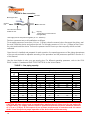
INDIRECT GAS FIRED AIR HEATERS
LD(E) SERIES
Model 120, 180, 240, 300, 350 and 400 outdoor
INSTALLATION AND SERVICE MANUAL
APPROVALS:
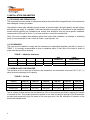
Our gas fired air heater of LD(E) series with output up to 400MBH are listed cETLus for Canada and United-States as
per standards CAN/CSA C22.2 No. 236-05 3rd edition and ANSI/UL 1995 respectively for an outside installation only.
Made by:
V2
WARNING
Installation and service must be performed by a qualified installer, service agency or gas supplier
qualified to followed and understand the instructions in this manual, the codes having jurisdiction as
well as those requires for the particular application of this equipment.
WARNING
Improper Installation, modification, adjustment or maintenance may cause property damage, personal
injury or death. Carefully read the installation and maintenance instructions before installing or
servicing this unit.
GAS ODOR
If a gas odor is detected:
1: Open all doors and windows;
2: Do not touch any electrical switch;
3: Extinguish all open flames;
4: Immediately notify your gas supplier.
WARNING
Do not store or use gasoline or other flammable vapors and liquids in the vicinity of this or any other
appliance.
WARNING
A gas equipment is not designed for use in a place that contains flammable vapors, combustible dust,
an atmosphere of hydrocarbon chlorides or silicone particles in suspension.
2
TABLE OF CONTENT
Abbreviations ........................................................................................................................................... 4
Table index ............................................................................................................................................... 4
Figure Index ............................................................................................................................................. 4
General..................................................................................................................................................... 5
1. Installation parameters ....................................................................................................................... 6
1.1. Receiving and preparation .......................................................................................................... 6
1.2. Clearances .................................................................................................................................. 6
1.3. Minimum air flow required ........................................................................................................... 6
1.4. Condensation .............................................................................................................................. 7
2. Installation instructions ....................................................................................................................... 7
2.1. General........................................................................................................................................ 7
2.2. Air duct ........................................................................................................................................ 8
2.3. Electrical connection ................................................................................................................... 8
2.4. Gas connection ........................................................................................................................... 9
2.5. Exhaust system ......................................................................................................................... 11
2.6. Combustion air .......................................................................................................................... 11
3. Start-up instruction ........................................................................................................................... 12
3.1. Wiring diagram .......................................................................................................................... 12
3.2. Main fan adjustment .................................................................................................................. 12
3.3. Burner adjustment ..................................................................................................................... 13
3.4. Ignition control ........................................................................................................................... 14
3.5. Flow switch for exhaust fan ...................................................................................................... 14
3.6. High limit control ........................................................................................................................ 15
4. Burner ............................................................................................................................................... 15
4.1. Capacity and operation pressure .............................................................................................. 16
4.1.1. Capacity and pressure Natural Gas ................................................................................ 16
4.1.2. Capacity and pressure Propane Gas .............................................................................. 17
4.2. Burner operation sequence ....................................................................................................... 19
4.3. Combustion control ................................................................................................................... 19
5. Shutdown procedure ........................................................................................................................ 21
5.1. Extended shutdown ................................................................................................................... 21
5.2. Emergency shutdown ................................................................................................................ 21
5.3. Restart after a flame failure ....................................................................................................... 21
6. Maintenance ..................................................................................................................................... 22
6.1. Assembly/dismantling................................................................................................................ 23
6.2. Corrosion ................................................................................................................................... 23
6.3. Gas valve .................................................................................................................................. 23
6.4. Exhaust fan ............................................................................................................................... 23
6.5. Ignition system sequence .......................................................................................................... 24
7. General warranty .............................................................................................................................. 25
Start-up form .................................................................................................................................... 26
3
ABBREVIATIONS
The following abbreviation of words and expressions are used in this manual:
BHP
: Break Horse Power
Btu/h
: British thermal unit/per hour
ºC
: Degree Celsius
w.c.
: Water column
ºF
: Degree Fahrenheit
h
: heure
PSI
: Pound per square inches of relative pressure
M
: meter
mm
: millimeter
MBH
: 1000 BTU/h
ft
: foot
in
: inche
in w.c.
: inche of water column
rpm
: rotation per minute
TABLES
1 : Minimum clearances ........................................................................................................................... 6
2 : Air flow................................................................................................................................................. 6
3 : Gas piping capacity .......................................................................................................................... 10
4 : Clearances from the gas exhaust of the unit ..................................................................................... 11
5 : a) Capacity – natural gas – S1 Control and S2 option ...................................................................... 16
b) Capacity – natural gas – Control option Si and SiB ...................................................................... 16
6 : a) Operating pressure – natural gas – S1Control.............................................................................. 16
b) Operating pressure – natural gas – Control option S2, Si and Sib ............................................... 16
c) Operating pressure – natural gas – Control option Sib (burner #1 only) ....................................... 16
7 : a) Capacity – propane gas – S1 Control and S2 option .................................................................... 17
b) Capacity – propane gas – Control option Si and SiB .................................................................... 17
8 : a) Operating pressure – propane gas – S1Control ........................................................................... 17
b) Operating pressure – propane gas – Control option S2, Si and Sib ............................................. 17
c) Operating pressure – propane gas – Control option Sib (burner #1 only)..................................... 17
9 : Combustion reading .......................................................................................................................... 20
10 : Inspection and maintenance ........................................................................................................... 22
FIGURES
1 : Component and position .................................................................................................................... 7
2 : Electrical connection and high voltage disconnect ............................................................................. 8
3 : Optional wall control panel ................................................................................................................. 9
4 : Gas connection ................................................................................................................................ 10
5: Exhaust fan with air pressure switch ................................................................................................ 14
6 : High temperature limit probe……………………………………… ................................. ………………15
7 : Air injection type burner ................................................................................................................... 15
8 : Main two-stage gas valve ................................................................................................................. 18
9 : Solenoid valve .................................................................................................................................. 18
10 : Main and solenoid valves arrangement........................................................................................... 19
11 : Exhaust fan with damper and guillotine adjustment ........................................................................ 20
12 : Ignition controller ............................................................................................................................. 24
4
GENERAL
This manual is designated for the ventilation units with heat exchanger gas bearing the LD(E) designation.
These devices bear the certification mark cETLus with code requirements CSA-C22.2-No236/UL 1995.
The capacity of your device and the type of gas can be found on the nameplate. The electrical
characteristics of the device are also listed on the nameplate.
All internal and external electrical installations must comply with the electrical schematics of the heater. For
more information, refer to the following sections of this manual and wiring diagram included with this unit.
Device installed in Canada:
The heater must be installed according to the code for installing gas appliances CAN/CGA-B149.1 in force
and the provincial regulations that apply to this category. In addition, the facility must be made according to
the rules of art and must meet code requirements in force in your area.
All electrical installations must meet the standards C22.1 Canadian Electrical Code and comply with local
codes applicable to that class of device.
Device installed in the United States:
The heater must be installed according to the code for installing gas appliances NFPA-54 in force and
regulations applicable to this category. In addition, the facility must be made according to the rules of art
and must meet code requirements in force in your area.
Electrical installations must meet the standards set out in the U.S. electrical code NFPA-70 and comply with
local codes applicable to that class of device.
5
1) INSTALLATION PARAMETERS
1.1) RECEIVING AND PREPARATION:
This equipment has been tested for operational safety at the plant before being delivered. If the product has
been damaged, contact your dealer.
Check that the name plate indicates the right number of required model, the right capacity, the right voltage
and that the gas supply is compatible. Read and familiarize yourself with all instructions in this installation
manual before beginning the installation and contact local authorities that may have specific installation
requirements for this type of device. If you have questions, contact the manufacturer.
Verify if the unit is supplied with separate options that require field installation, for example a modulating
probe, a room thermostat, a seal, a fresh-air intake, a gas regulator, etc.
1.2) CLEARANCES:
The units must be installed to comply with the clearances to combustible materials such that it is shown in
TABLE 1. It is strongly recommended to have no obstacles within 10 feet (3m) of the fresh air intake to
avoid water and snow from entering.
TABLE 1 – Minimum clearances
TOP
FRONT
REAR
SIDES
FLOOR
VENT
CONNECTOR
FRONT
(ACCES PANEL)
25 mm
1 inch
25 mm
1 inch
25 mm
1 inch
25 mm
1 inch
25 mm
1 inch
610 mm
24 inches
610 mm
24 inches
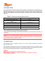
1.3) MINIMUM AIR FLOW REQUIRED :
The minimum air flow in each unit is limited by the temperature rise that should not exceed 120 º F (67 º C)
when the burner operating at full capacity.
TABLE 2 – Air flow
Air flow
CFM (l/s)
Max.
Min.
Min. (reduce flow
contact open)
LD(E) 120
LD(E) 180
LD(E) 240
LD(E) 300
LD(E) 350
LD(E) 400
1481 (699)
740 (350)
2222 (1049)
1111 (524)
2963 (1398)
1481 (698)
3705 (1749)
1851 (872)
4321 (2039)
2160 (1018)
4938 (2330)
2469 (1164)
444 (210)
667 (314)
889 (419)
1111 (523)
1296 (611)
1481 (698)
The air volume of these devices can be reduced to 60% of the maximum specified by opening the contact
of reduced air flow. This contact reduces the position of the fresh air damper opening to the potentiometer
set point and prevents the high fire mode on the main gas valve. See the sequence of operation of the
burner with multiple levels.
6
1.4) CONDENSATION :
The combustion produces huge amounts of water vapor. This water vapor is contained in the flue gas of the
appliances and can condense if the temperature falls below the dew point. The condensate should be
controlled by taking certain precautions to prevent their formation. They can settle in the tubes, the
collector, the fan, and exhaust system. To avoid damaging the heat exchanger, just follow the directions for
installing the drainage system specified in Section 2.5 of this manual.
To avoid the accumulation of condensation in the flue gas collector, it is possible to add a drain ensuring to
prevent freezing of condensation and install a gooseneck. The drain is located on the flue gas manifold
below the exhaust fan.
WARNING: A safe and efficient operation requires regular inspection and proper maintenance of
drainage system. A broken exhaust system or a gas leak is dangerous and can cause death. It can
also prevent proper operation of the device and void the warranty.
2) INSTALLATION INSTRUCTIONS
2.1) GENERAL
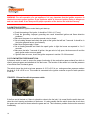
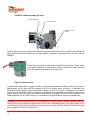
The LD(E) units model are designed for outdoor installation on a roof, a structure or ground on a concrete
base. The air intake must be located so as to avoid the snow, rain, flammable or toxic gases and other
substances harmful to the health of occupants and the unit from entering in the air intake of the air heater.
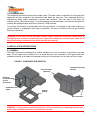
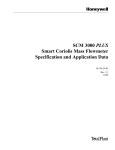
FIGURE 1: COMPONENT AND POSITION
Fresh air intake
(Optional)
Combustion flue gas
exhaust
Electrical
connection with
service
disconnect.
Combustion air
intake
Sealing
gasket
Gas connection
WARNING: It is important to mechanically fix the unit to the roof base or supporting structure with
bolts or other suitable attachment to prevent its movement.
7
2.2) AIR DUCT
The ducts are provided on site and it is important that they be installed to:
-Avoid air leakage (seal);
-Respect the pressure loss calculated in the design;
-Be isolated if they are in an unheated space;
-Prevent air direction change as little as possible;
-Have an access door to inspect the heat exchanger;
-Be rigid and self-supporting;
-Have a low limit sensor installed;
-Respect the rules of art.
Where fire dampers are used in the ducts, they must be equipped with trigger connected to the electrical
safety control circuit, so that the heater stops when there is presence of intense heat in the ducts or when
there is no air flow. These electrical triggers must be arranged so that the safety circuit is powered only
when fire dampers are fully open.
WARNING: If the unit does not come with a minimum temperature sensor, the installer should add
this type of probe to prevent any risk of frost in the interior of the building.
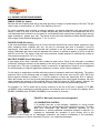
2.3) ELECTRICAL CONNECTION:
The electrical connections and grounding must conform to local standards. In Canada, refer to the
Canadian Electrical Code CSA C22.1 and the United States, NFPA 70. In addition, this connection must be
installed according to the rules of art and must meet local codes having jurisdiction.
The connection must be made at the prescribed place within the electrical control panel. See the wiring
diagram supplied with the unit.
FIGURE 2: Electrical connection and high voltage disconnect.
8
FIGURE 3: Optional wall control panel
Model "S" (10 1/2" l x 5 1/2" h)
Model "M" (10 1/2" l x 10 1/2" h)
STANDARD EQUIPEMENT
Selector (stop / fan / burner)
Fan operation light
Burner operation light
Terminal blocks
Temperature selector ("M" model only)
Model "S"
WARNING : If a portion of the wiring supplied with the unit must be replaced or if wiring must be
added to the unit, it must be replaced by wiring sheathed with an approved material to withstand a
temperature of 221ºF (105ºC) or more. The wirings of the flame sensing probe, the igniter and
control of high limit must be replaced by wiring sheathed with an approved material to withstand a
temperature of 302ºF (150ºC) or more.
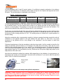
2.4) GAS CONNECTION:
The gas supply piping must be designed according to the requirements of installation of gas appliances of
the edition in force of the Code CSA-B149.1 for Canada and the ANSI Z 223.1 and NFPA 54 for the United
States. In addition, the same piping must be installed according to the rules of art and must meet local
codes having jurisdiction.
The units were designed to operate with a supply pressure of not more than 14 in.w.c (3.5Kpa). For a
higher pressure system, a high pressure regulator must be installed. Its capacity should be designed to
reduce supply pressure to a level below the maximum prescribed at any time (off or on). In addition, the
regulator must be able to maintain a stable supply pressure at reduced capacity. The reduced capacity of
these units can be as low as 5% of their maximum capacity.
The units were manufactured for use with natural gas having a calorific value of 1007 Btu / cubic foot. If the
gas distributor does not meet this specification, contact the manufacturer for proper selection of the orifices.
Close to and upstream of the unit, a union followed by an approved manual valve should be installed (see
FIGURE 4). A gas connection must be provided to allow a reading of the supply pressure. Check with a
leak detection solution to all joints of the pipe for gas leaks.
9
FIGURE 4: Gas connection
Gas inlet*
Manual gas valve
Outlet to
unit
Gas inlet*
The connection must be
outside the unit
Drip leg
(check with your local codes for
this application)
*Gas supply from the low pressure regulator (14’’ w.c. maximum)
Perform a pressure test on all installations as follows:
For a supply pressure of more than 14 in w.c. (3.5Kpa), close the manual valve, disconnect the piping, seal
the ends, install the device and perform the test. For a supply pressure of 14 in w.c. (3.5Kpa) or less, close
the valve and install the device. Perform the pressure test to ensure you have a quality device and well
calibrated
Once the unit is installed and prepared for safe operation, the operating pressure of the piping downstream
of the gas valve should be adjusted according to the procedure and the pressures specified in Section 4.1
of this manual.
Use the chart below to size your gas supply pipe. For different operating pressures, refer to the CSAB149.1 codes in Canada and ANSI Z 223.1/NFPA 54 for the United States.
TABLE 3 – Gas piping capacity
GAS PIPING CAPACITY (MBH)
For an operating pressure of 7 in w.c. - For natural gas with a pressure drop of 1 in.w.c.
External diameter of piping (in)
Length
(ft)
3/8
1/2
5/8
3/4
7/8
1-1/8
1-3/8
10
35
72
147
257
364
778
1401
20
30
24
19
50
40
101
81
176
142
250
201
535
429
9 63
7 73
40
17
34
69
121
172
368
6 62
50
60
15
30
61
107
152
326
5 86
13
12
27
25
56
51
97
90
138
127
295
272
5 31
4 89
11
23
48
83
118
253
4 55
11
10
22
21
45
42
78
74
111
105
237
224
4 27
4 03
8.9
18
37
65
93
198
3 57
8.1
7.4
17
15
34
31
59
55
84
77
180
165
3 24
2 98
70
80
90
100
125
150
175
CAUTION: All pipe unions must be tested before starting the unit. Never test for gas leaks with
an open flame. The supply pressure must be tested and must not exceed a maximum pressure
of 14 in w.c. (3.5Kpa). A non respect of one of these requirements is hazardous and can cause
death. It can also prevent proper operation of the device and void the warranty.
10
2.5) EXHAUST SYSTEM:
It is very important to not direct the output to a fresh air intake, a combustion air inlet of another device, an
opening of the building or wall. It is possible that the clearances given in TABLE 4 are not suitable because
of the horizontal projection of the combustion products. Particular attention should be made to each
application. A safe appropriate distance may be added to the clearance shown in TABLE 4 depending on
application.
TABLE 4 – Clearances from the gas exhaust of the unit*
Structure
Motorized air intake less than 3 m (10 ft)
Combustion air inlet of another device
Door, operable window, gravity air intake or any other
opening
Electric or gas meter, regulator**
Minimal clearance from vent cap***
3 m (10 ft) on side or 0,9 m (3 ft) over
1,8 m (6 pi)
3 m (10 ft) on side or 0,9 m (3 ft) over
Vent outlet of another device
0,9 m (3 ft)
Building or adjacent wall or guard
Sidewalk or parking vehicles
Ground
1,8 m (6 ft)
2,1 m (7 ft) over
0,3 m (1 ft) over the snow level
Obstacle around the unit
Over any obstacle from less than 1.8 m (6 ft)
0,9 m (3 ft) on side
*If the local codes have more restricted clearances, you must respect them.
**Do not install the chimney outlet over a service regulator or gas meter.
***Take precautions to avoid installing vent outlet where snow accumulation can be done either by a shift from a roof
or near a wall.
WARNING: A safe and efficient operation requires an adequate evacuation of combustion gases. A
broken exhaust system or a gas leak is dangerous and can cause death. It can also prevent proper
operation of the device and void the warranty.
2.6) COMBUSTION AIR :
Gas combustion requires a significant amount of air to ensure complete combustion and maximum
efficiency of the device.
The combustion air intake must not, at any time, be blocked or obstructed by snow or otherwise. The air
intake opening must be located a minimum of 12 inches (300 mm) above any surface that can accumulate
snow. If your area has high annual snowfall, it is better to increase this clearance.
WARNING:
NEVER obstruct the combustion air intake or ventilation.
NEVER install a gas appliance in a room that has no outside air supply for combustion.
NEVER install this unit inside.
11
3) START-UP INSTRUCTION
IMPORTANT
The following information should be used only by qualified technician in gas appliance
(with qualification cards), with knowledge of electricity and ventilation.
CAUTION
It is important to not smoke during the start-up of the heater.
Equipment required for start-up:
Voltmeter
Ammeter
Temperature reader
Combustion analyser
Tachometer (read speed of the fan and motor)
Velocity pressure sensor (Pitot tube)
Gas pressure gauge
o Scale of 0 to 5 in w.c.
o Scale of 0 to 15 in w.c.
3.1) WIRING DIAGRAM:
The wiring diagram is located inside the access panel in an envelope and a copy is pasted on the inside of
the access panel. It is important to understand the sequence of operation of the electrical diagram prior to
the start or work on the device.
3.2) MAIN FAN ADJUSTMENT
Before undertaking checks on gas, it is important to have good air flow. Adjustment of the air flow is
required to obtain the required capacity and minimum capacity of air to prevent overheating of the
exchanger.
- Check the voltage of each phase to the main switch.
- Check the direction of fan rotation and interchange phases if needed.
- Make sure that the overload relay of the switch is set to the maximum current (FLA) indicated on the
motor nameplate.
- Check alignment and belt tension (do this test without power supply).
- When the dampers are fully open, take a reading of the amperage on each phase of the motor, the
rotation speed of the fan RPM and see if they meet the criteria for project design placed on the fan
curve.
- Make a test air flow and adjust the fan speed necessary to get the proper air flow.
12
3.3) BURNER ADJUSTMENT
It is very important to ensure that the installation of the unit complies with all the instructions in this manual.
You must ensure that it meets all the requirements for installation of gas appliances up to date edition of the
CSA B149.1 code for installation in Canada and the ANSI Z223.1/NFPA 54 for installation to United States.
The unit must be installed according to the rules of art and must meet code requirements in force in your
area. Consult the relevant authorities before installation and startup.
Additional suggested checklist before starting the unit:
1.
2.
3.
4.
5.
6.
7.
8.
Check the strength of the installation. The unit must be well supported and level;
Check clearances of combustible material specified in this manual and make sure to respect them;
Check the supply of combustion air;
Check the exhaust system and make sure it meets the requirements prescribed in this manual and the
codes in your area;
Check gas piping for leaks and the supply pressure;
Check the wiring, make sure that the wires used the circuit breaker and fuses have good rating;
Make sure there is good airflow in the unit;
Check the location of temperature sensors and the control sequence without gas supply.
Ignition sequence :
1. Adjust the heating demand to the off position;
2. Open the main manual gas valve;
3. Open the manual gas valve on the electric combined valve;
4. Turn power on of the unit;
5. The fan should start and the dampers position should be set correctly;
6. Adjust the heating demand of the controller to the desired temperature;
7. The flue gas exhaust fan starts;
8. The flow switch in the exhaust fan closes the contact;
9. A pre-purge of 30 seconds occurs;
10. The ignition occurs, the gas valve opens and the burners ignite instantly.
If this sequence is not followed properly, check wiring, installation and the gas supply and try again.
Additional suggested checklist after start-up:
1. With the burner operating at full capacity, measure the gas pressure to the tubing (immediately after the
main gas valve). The pressure at full capacity should be consistent with data from section 4.1 of this
manual;
2. Turn OFF then ON the burner while waiting one minute between each cycle to verify that the lighting is
soft and without flashback. On systems with multiple levels, make sure that all heating systems work
well in the sequence of operation of the burners described in Section 4.2;
3. Observe the flame at full capacity, ensuring a good combustion with the use of a calibrated combustion
analyzer. Follow the instructions in Section 4.3 to determine the characteristics of such devices;
4. Check the high limit controller by cutting the air flow. It should stop the burner in about a minute and
restarts once it is cooled;
5. Check the air flow switch in the gas exhaust fan by blocking the flue outlet. The burner should stop
immediately and re-ignite after a pre-purge of 30 seconds;
6. Make any checks deemed necessary depending on the application, options selected and the mode of
operation specific to this project;
7. Leave a copy of this manual in a safe place near the unit.
13
WARNING: For safe operation of a gas appliance, it is very important that the ignition sequence is
checked to ensure proper ignition. A gas appliance which is incorrect ignition timing is dangerous
and can cause death. It can also prevent proper operation of the device and void the warranty.
3.4) IGNITION CONTROL:
Verification procedure of ignition control during unit start-up:
Check the spacing of the igniter, it should be 0,164 in (4,17 mm).
Check the grounding. Improper grounding can cause intermittent ignition and flame detection
problems.
Make sure the power is on and the manual valve is closed.
Set an heating demand and check the spark at the igniter that will last 7 seconds. It should be in
the igniter gap and have a good intensity.
Make sure the gas supply is open.
Set an heating demand and check the spark igniter to light the burner as expected in 3 to 5
seconds.
Make sure that after 7 seconds of ignition, the gas valve is fully open, the burners are lit and the
spark igniter makes no more sparks.
If ignition does not occur, check the ignition sequence in section 6.5 of this manual.
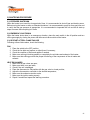
3.5) FLOW SWITCH FOR EXHAUST FAN:
A pressure switch is used to ensure the proper functioning of the combustion gases exhaust fan which is
used to exhausts gases and admitted air into the burner. The function of this sensor is to read the presence
of a sufficient flow of exhaust gases.
The switch closes the circuit at a lower pressure of -0.53 ± 0.03 in w.c. and opens when pressure reaches
the level of -0.40 ± 0.03 in w.c. This contact is connected to the ignition controller as proof of safe operation
of the fan.
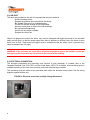
FIGURE 5 : Exhaust fan with air pressure switch
If the flue vent is blocked or if there is a bend too close to the fan inlet, it is normal that the switch does not
close the circuit causing a shutdown of the burner. It is also possible that the switch closes the circuit when
the gases are cold and not closes when the gases are hot. This indicates a problem that must be corrected
immediately.
14
WARNING: A safe and efficient operation requires an adequate evacuation of combustion gases.
Bypassing a safety device such as a pressure switch on a gas appliance is dangerous and can
cause death. It can also prevent proper operation of the device and void the warranty.
3.6) HIGH LIMIT CONTROL:
All devices use a high temperature control limit installed to detect a high temperature in the exchanger. The
main cause of the upper limit circuit opening is a lack of air.
A lack of air can be caused by several reasons, either : a fan failure, a broken belt, a
component, an insufficient tight belt, reverse motor rotation, clogging filters, too high
gas capacity, etc.
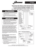
Figure 6: High temperature limit probe
A second high temperature sensor is installed near the burner to detect a flame outside the heat exchanger.
If a problem related to this probe is detected, it must be repaired immediately.
The high limit sensors are not adjustable and must be replaced with compatible components installed in the
same place and with the same temperature setting. Consult the manufacturer for replacement parts.
WARNING: A lack of tube cooling will cause an accelerated degradation of the area not
cooled and it can also prevent proper operation of the device and void the warranty.
Degradation can cause a leak of flue gases in the air. Leakage of combustion gases is
dangerous and can cause death.
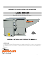
4) BURNER :
These units use injection and venturi type burner. They allow a stable flame and efficiently without flash
back, and this, without any adjustment. The burners are installed on removable media to allow an annual
inspection of tubes. The burners should be aligned with the longitudinal axis of the tubular heat exchanger.
Contact of the flame on a non centered heat exchanger will cause a degradation and even perforation of
the exchanger. In a device with the option Sib, the burners do not all have the same capacity. See Tables
5A and 5B for more information.
Figure 7 : Air injection type burner
Model 120, 180 and 240
Model 300, 350 and 400
15
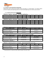
4.1) CAPACITY AND OPERATION PRESSURE:
Each burner uses an orifice with a specific opening according to its rated capacity. The following tables
provide the capacity and operating pressure for each model depending on the control option selected.
4.1.1) Capacity and pressure Natural Gas :
TABLE 5A – Capacity – natural gas – S1 Control and S2 option
Heat exchanger model
LDE-120 LDE-180 LDE-240 LDE-300 LDE-350 LDE-400
High fire capacity (100%) (S1 and S2)
120 MBH 180 MBH 240 MBH 300 MBH 350 MBH 400 MBH
Low fire capacity (60%) (S2 only)
72 MBH 108 MBH 144 MBH 180 MBH 210 MBH 240 MBH
TABLE 5B – Capacity – natural gas – Control option Si and SiB
Heat exchanger model
LDE-120 LDE-180 LDE-240
Burner capacity high fire (100%)
30 MBH
30 MBH
30 MBH
Burner capacity low fire (60%)
18 MBH
18 MBH
18 MBH
#1 burner capacity SiB only, low fire
12 MBH
12 MBH
12 MBH
TABLE 6A – Operating pressure - natural gas – S1Control
Heat exchanger model
LDE-120 LDE-180 LDE-240
Inlet pressure max. (min)
14 (7) in.w.c.
Operating pressure High fire (100%)
Altitude from 0 to 2000 foot
Operating pressure High fire (100%)
Altitude from 2001 to 4500 foot
LDE-300
50 MBH
30 MBH
20 MBH
LDE-300
LDE-350
50 MBH
30 MBH
20 MBH
LDE-400
50 MBH
30 MBH
20 MBH
LDE-350 LDE-400
14 (7) in.w.c.
3.5 in.w.c.*
4.2 in.w.c.*
2.3 in.w.c.*
2.8 in.w.c.*
TABLE 6B – Operating pressure - natural gas – Control option S2, Si and SiB**
Heat exchanger model
LDE-120 LDE-180 LDE-240 LDE-300 LDE-350 LDE-400
Inlet pressure max. (min)
14 (7) in.w.c.
14 (7) in.w.c.
Operating pressure High fire (100%)
Altitude from 0 to 2000 foot
Operating pressure High fire (100%)
Altitude from 2001 to 4500 foot
**Except burner #1 (see table 6C)
3.5 (1.3) in.w.c. *
4.2 (1.6) in.w.c. *
2.3 (0.9) in.w.c. *
2.8 (1.1) in.w.c. *
TABLE 6C – Operating pressure - natural gas – Control option Sib (Burner #1 only)
Heat exchanger model
LDE-120 LDE-180 LDE-240 LDE-300 LDE-350 LDE-400
Inlet pressure max. (min)
14 (7) in.w.c.
14 (7) in.w.c.
Operating pressure High fire (100%)
Altitude from 0 to 2000 foot
Operating pressure High fire (100%)
Altitude from 2001 to 4500 foot
5.0 (0.9) in.w.c *
5.0 (1.0) in.w.c. *
3.5 (0.6) in.w.c. *
3.5 (0.7) in.w.c.*
*The gas pressure is measured at the manifold (output of the main valve).
16
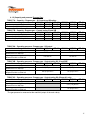
4.1.2) Capacity and pressure Propane Gas:
TABLE 7A – Capacity – Propane gas – S1 Control and S2 option
Heat exchanger model
LDE-120 LDE-180 LDE-240 LDE-300 LDE-350 LDE-400
High fire capacity (100%) (S1 and S2)
120 MBH 180 MBH 240 MBH 300 MBH 350 MBH 400 MBH
Low fire capacity (60%) (S2 only)
72 MBH 108 MBH 144 MBH 180 MBH 210 MBH 240 MBH
TABLE 7B – Capacity - Propane gas – Control option Si and SiB
Heat exchanger model
LDE-120 LDE-180 LDE-240
Burner capacity high fire (100%)
30 MBH
30 MBH
30 MBH
Burner capacity low fire (60%)
18 MBH
18 MBH
18 MBH
#1 burner capacity SiB only, low fire
TABLE 8A – Operating pressure - Propane gas - S1Control
Heat exchanger model
LDE-120 LDE-180 LDE-240
Inlet pressure max. (min)
14 (12) in.w.c.
Operating pressure High fire (100%)
Altitude from 0 to 2000 foot
Operating pressure High fire (100%)
Altitude from 2001 to 4500 foot
LDE-300
50 MBH
30 MBH
40 MBH
LDE-300
LDE-350
50 MBH
30 MBH
40 MBH
LDE-400
50 MBH
30 MBH
40 MBH
LDE-350 LDE-400
14 (12) in.w.c.
10.0 in.w.c.*
11.0 in.w.c.*
6.9 in.w.c.*
7.6 in.w.c.*
TABLE 8B – Operating pressure - Propane gas - Control option S2, Si and SiB**
Heat exchanger model
LDE-120 LDE-180 LDE-240 LDE-300 LDE-350 LDE-400
Inlet pressure max. (min)
14 (12) in.w.c.
14 (12) in.w.c.
Operating pressure High fire (100%)
Altitude from 0 to 2000 foot
Operating pressure High fire (100%)
Altitude from 2001 to 4500 foot
**Except burner #1 (see table 8C)
10.0 (3.5) in.w.c.*
11.0 (4.0) in.w.c.*
6.9 (2.3) in.w.c.*
7.6 (2.8) in.w.c.*
TABLE 8C – Operating pressure - Propane gas - Control option Sib (Burner #1 only)
Heat exchanger model
LDE-120 LDE-180 LDE-240 LDE-300 LDE-350 LDE-400
Inlet pressure max. (min)
14 (12) in.w.c.
Operating pressure High fire (100%)
Altitude from 0 to 2000 foot
Operating pressure High fire (100%)
Altitude from 2001 to 4500 foot
11.0 (7.0) in.w.c.*
7.6 (4.8) in.w.c.*
*The gas pressure is measured at the manifold (output of the main valve).
17
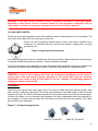
FIGURES 8: Main two-stage gas valve
High fire adjustment
Low fire adjustment
Manifold pressure
reading
Figure 8 shows the screws HI and LO to adjust the high and low pressure in the manifold tubing. Adjust the
high pressure first and then adjust the low then make a verification of high pressure to ensure it has not
changed.
Figure 9 shows a solenoid valve used with the Si and Sib option. These valves
are installed upstream of each burners and the orifices are installed on that
valve. No adjustment is required on these valves.
Figure 9: Solenoid valve
At high altitude, a decrease in oxygen in the air for combustion decreases the ability of a device at a rate of
approximately 4% for each 1000 feet elevation (304 m) in altitude above sea level it is therefore very
important to reduce the gas pressure according to Tables 6 A, B or C (or 8A, B, C) depending on the option
of your device. Without this pressure reduction, combustion will be incomplete and excessive production of
carbon monoxide (CO) will occur. It should be noted that the net capacity of the unit will be reduced in the
same proportion (4% per 1000 ft (304m)). For operations at a higher altitude, consult the manufacturer.
WARNING: Carbon monoxide (CO) is an odourless and deadly gas. A device operating with the
wrong orifices may produce a high amount of CO in the combustion gases. This high amount of CO
can also prevent the proper functioning of the device and may void the warranty. Exposure to this
gas is dangerous and can cause death.
18
4.2) BURNER OPERATION SEQUENCE:
SIMPLE STAGE (S1 Option):
Devices with the S1option come with a one stage gas valve, running on a power supply of 24 volts. The gas
valve is open or closed either 0 or 100% of the capacity of the unit.
S1 option combined valve includes a pressure regulator, an internal redundant valve and manual valve
closure. Control of a valve at one level is simple and provides good accuracy of the temperature with a 24
volts thermostat well localized or a dry contact in a centralized control system when heating a large enough
space (warehouse , garage, gym, etc.). The design of the main valve maintains a stable manifold pressure
with a range of inlet pressure ranging from 7'' w.c. to 14''w.c.
DOUBLE STAGE (S2 Option) :
In the event that heated a smaller room or a room where the comfort level must be higher (classroom, large
office, shopping center, exhibition hall, etc.), the use of a two-stage gas valve is essential. It must be
operated by a two-stage 24 volt thermostat well localized or two dry contacts of a centralized control
system. Redundant gas valves used are adjusted at the factory to maintain a capacity of 100% at high fire
and 60% at low fire. The design of the main valve maintains a stable pressure in manifold with a range of
inlet pressure ranging from 7''w.c. to 14''w.c.
MULTIPLE STAGES (Si and Sib Option):
A multi-stage device has a solenoid valve installed at each burner. Each of the solenoids is controlled
individually, allowing a reduction in the capacity of the unit by the number of tubes on and the setting of the
two-stage valve. This type of modulation control is required in an application of fresh air and is suggested
for comfort heating in a specific application (laboratory, museum, senior citizens residence).
For this option, a temperature controller with relay outputs is included to start levels individually. The ignition
sequence will be in the following order: a heating demand, the first burner turns on 60% (40% Sib) of the
burner capacity followed by number 2, 3, 4 till the maximum of tubes are themselves 60% of capacity.
When the burners are lit on low fire and heating demand increases (the control signal increases), the main
valve increases the pressure of the manifold tubing to feed the burners at 100% capacity. Instantly, the
controller will reduce the amount of burners fed in order to have a linear increased heating capacity.
For example: If a 120 Si model with 4 burners turned on at low fire it will have a capacity of 72 MBH
(4x18MBH). After increasing the manifold pressure and reduction from 4 to 3 burners, the capacity will be
90 MBH (3x30MBH) then 120 MBH (4x30MBH) for an increase to 4 burners.
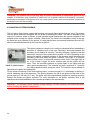
FIGURE 10: Main and solenoid valves arrangement
4.3) COMBUSTION CONTROL:
It is possible that due to the transport, installation or during normal
operations of this unit, maladjustment of the combustion occurs. To restore
data from combustion and thermal efficiency specified by the
manufacturer, a recently calibrated combustion analyzer is required. It is
important to understand the operation of such devices prior to the
adjustment of the burner as an inadequate combustion can produce overheating of the exchanger,
excessive production of carbon monoxide (CO) and / or a carbonized exchanger.
19
For units equipped with S1 and S2 control options, it is sufficient to sample combustion in the chimney
outlet near the exhaust fan. The samples must be taken at high fire for S1option and high and low fire for
S2 option. The results should be comparable to the following:
Table 9 – Combustion reading
Model/Reading
CO2 (%)
Excess air (%)
CO
Thermal efficiency
LDE 120, 180 et 240
LDE 300, 350 et 400
5 to 7%
7.5 to 9%
55 to 80%
35 to 55%
<100 ppm
<100 ppm
80-82%
80-82%
For units equipped with the Si or Sib control option, take three samples in two different places depending on
the modulation setting. The first sample must be taken in an opening provided for that purpose on the
collector of exhaust gases. This opening is to the right of the exhaust fan and under the insulation. The
probe must be placed at the mouth of the burner tube # 1 of the exchanger.
For this test, it is important that the firing rate is adjusted to obtain the high pressure to the manifold and the
minimum burners lit for this setting. For example, the model 400 of 8 natural gas burners, you must have
five burners lit with a tubing pressure of 4.2''w.c. This setting serves as a reference for a good operation on
all other setting.
Adjust the combustion after a representative sample by closing or opening the shutter manual fan outlet of
combustion or the guillotine placed on the gas collector box (see Figure 11). Note that a very small
movement of the guillotine will be a big change in the combustion. Use the samper to make final
adjustments.
Following the adjustment of the plan according to data from above table, it will be needed to check the fire
setting up and down with all burners on. For example, the model 400 of 8 burners, check the flue to the
chimney outlet manifold pressure of 1.6'' w.c. and 4.2'' w.c. this with all burners on. To change the pressure
or the firing rate to the manifold, adjust the 0-10Vdc signal to the multiple levels controller up, you'll get the
high pressure (high fire). For low pressure (low fire), disconnect the 24V power supply that powers up the
high pressure of the main valve.
Note that the combustion reading from analyzer differ depending on the calibration, the gas pressure, air
temperature and quantity on the exchanger, dust and wind environment. If you cannot reach the specified
data in Table 9, contact the manufacturer.
Damper adjust
to 30° at
factory
Guillotine
FIGURE 11: Exhaust fan with damper and guillotine adjustment.
WARNING: Carbon monoxide (CO) is an odourless and deadly gas. A device operating with the
wrong orifices may produce a high amount of CO in the combustion gases. This high amount of CO
can also prevent the proper functioning of the device and may void the warranty. Exposure to this
gas is dangerous and can cause death.
20
5) SHUTDOWN PROCEDURE
5.1) EXTENDED SHUTDOWN
When the heater is not used for a long period of time, it is recommended to shut off gas and electric power.
Before turning the heater on after an extended shutdown, it is recommended to purge air from gas lines and
to verify that the gas pressure is appropriate. It is recommended to inspected the unit and do all start-up
steps to ensure that everything is in order.
5.2) EMERGENCY SHUTDOWN
When the heater shuts down in an emergency situation, place the main switch in the off position and turn
off the gas supply by closing the power and the manual valve outside of the heater.
5.3) RESTART AFTER A FLAME FAILURE
Following a flame failure alarm, check the following:
FAN
1.
2.
3.
4.
5.
Place the switch to the OFF position;
Check the fan belts and replace or adjust them if necessary;
Check the condition of filters and replace if needed;
Make sure nothing is blocking partially or completely the air intake and exhaust of the heater;
Make sure that nothing prevents the proper functioning of the components of the air intake and
exhaust.
HEAT EXCHANGER
1. Make sure all gas valves are open;
2. Make sure there is no gas leaks;
3. Check if the unit is damaged;
4. Place the disconnect to ON position with the gas valve in closed position;
5. Adjust the thermostat or controller to the desired temperature;
6. Make sure the exhaust motor fan works;
7. Make sure the ignition works properly;
8. Repair if needed and repeat the start-up procedure.
21
6) MAINTENANCE :
The instructions for installation and maintenance of this manual are designed to help a qualified technician.
To ensure optimum performance and safety, all gas equipment must be properly inspected and maintained
periodically. A list of maintenance tasks to be performed is provided in the following table:
TABLE 10 : Inspection and maintenance
VERIFICATION
CHECKLIST
WEEKLY
Check air filters – Replace them if necessary.
Check bearings lubrification, adjust the screws on the collar and
condition of belts.
Ensure that no combustible material is stored near the heater.
Make sure nothing is blocking the air inlet and outlet from the
heater and the combustion air inlet.
Check flame and combustion quality.
MONTLY
BIANNUAL
ANNUAL
Check the fresh and return air dampers operation.
Ensure that all safety controls are functional.
Check the exhaust system and the pressure switch.
Ensure there is no gas leaks in the piping (fittings and valves) and
check the gas pressure at the manifold.
Check all electrical connections.
Make sure the fan and motor are firmly anchored.
Verify the control sequence and ignition system.
Clean the cage and the wheel fan of the burner.
Clean the burners and orifices.
Clean the inside and outside of the exchanger, remove surface
rust, dust, etc.
Clean the flame sensor probe and the igniter.
IMPORTANT
BEFORE START-UP AND AFTER 8 HOURS OF OPERATION
- Check the alignment and lubrification of bearings;
- Check the bearing collars;
- Check the alignment and belt tension;
AFTER 48 HOURS OF OPERATION
- Check belt tension.
22
WARNING: If you turn off the power of the unit, close the manual gas valve.
WARNING: If the air contains a large amount of dust, a second cleaning may be required during the
heating season. Failure to clean gas appliance is dangerous and can cause death. It can also
prevent proper operation of the device and void the warranty.
6.1) ASSEMBLY / DISMANTLING:
For dismantling and assembly of a component, refer to the appropriate section. Always follow the steps in
commissioning described in Section 3 of this manual before turning on gas equipment.
6.2) CORROSION:
Corrosion can occur in exhaust ducts and in the heat exchanger, if the combustion air contains chemical
vapors. Products containing chlorine are the most frequently encountered. In the process of combustion,
the chlorine molecules are converted into hydrochloric acid, which is very aggressive on metals, even
stainless steel 300 series. Such corrosion can lead to very fast degradation of the exchanger.
The following are examples of sources of corrosion: aerosols, cleaning solvents, refrigerants, pool
chemicals, calcium and sodium chloride, waxes, glues, etc. In the presence of these products, the heat
exchanger and vent system may in one heating season to be damaged enough to need replacing. Such
products should not be stored or disposed of so that their vapors can contaminate the combustion air or
come into contact with the gas appliance.
WARNING: Failure to meet these requirements is dangerous and can cause death. It can also
prevent proper operation of the device and void the warranty.
6.3) GAS VALVE:
The main gas valve is supplied with 24 volts from the ignition controller. The primary function of the gas
valve is shut off gas supply to the burner by a request to stop from the ignition controller. The second
function is to reduce the inlet pressure to the pressure of operation necessary to the tubing using a
diaphragm type regulator. The pressure is adjustable with an adjustment screw which is located under the
unscrewed protective cover. See Section 4 of this manual. The solenoid valves on all burners are supplied
with 24 Volts or 120 Volts.
WARNING: The valve is the only way to ensure an automatic shutdown of gas flow. It is therefore
very important to ensure that the gas supply pipe is clean and contains no metal burrs or water.
Incomplete closure of the valve is dangerous and can cause death. It can also prevent proper
operation of the device and void the warranty.
6.4) EXHAUST FAN:
The gas combustion exhaust fan motor is permanently lubricated, clean surface as needed. It runs on a
voltage 110/1/60 (see the nameplate and model number). If it is necessary to replace one of the following:
motor, fan cage or squirrel cage, it is very important to replace them with original parts only. See photo of
the exhaust fan (figure 11).
23
WARNING: The exhaust fan is the only way to ensure evacuation of combustion gases to the
outside. It is therefore very important to make sure it is in good condition and properly connected.
Inadequate evacuation is dangerous and can cause death. It can also prevent proper operation of
the device and void the warranty.
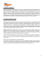
6.5) INGNITION SYSTEM SEQUENCE
This unit has a direct ignition system that monitors and controls flame ignition and gas valve. This system
uses an ignition distributor combined with the probe for detecting the flame. The flame is detected by the
method of correction works as follows: a weak electrical signal isolated from the ground is applied to the
detection probe through the ignition controller. When there is a flame in the immediate vicinity of the rod,
the flame acts as a conductor to the ground. It is said that the flame corrects and completes the circuit DC
which is automatically detected by the controller of ignition.
The ignition sequence is simple, but it must be understood before undertaking a
correction of a defective unit or new one. Following a thermostat demand, the
secondary circuit feeds a 24 volt relay. The relay produces a contact to start the
exhaust fan running on the current primary system 110 volts. Depending on the
exhaust fan applies a negative pressure on the pressure switch that closes the
secondary circuit and feeds the ignition controller. Pre-purge of 30 seconds
before ignition occurs. In series with pressure switch, there is two high limits of
air. If one of them is open, the circuit remains open and the ignition will not
occur. Then, the controller produces an ignition spark to the igniter and gas
FIGURE 12 : ignition controller
valve opens simultaneously. The controller will wait a maximum of 7 seconds
for a flame detection before closing the valve. The controller will not attempt to
light the burner again if the lighting fails.
For the proper functioning of the flame sensing probe, a minimum signal of 1.5 microamps is required. It
can be measured with a microammeter. The spacing between the rod of the ignitor and the stem of the
ground must be 0.164 inch (4.17 mm). The igniter must be connected and grounded in ensuring continuity
between the burner and ignition controller. For more information on the ignition controller, refer to the
operation manual and installation of the controller provided by the manufacturer.
WARNING : The ignition system operates at high voltage. For safe handling, disconnect the power
before handling the ignition components.
24
7) GENERAL WARRANTY:
During the first year following the installation of our product, or eighteen (18) months from the date of shipment by
Bousquet Technologies Inc., according to the first of these events, but subject to the terms and conditions of the
this, we will provide free any part component of our product with a defect or manufacturing defect. Any parts
supplied in replacement is guaranteed for the unexpired portion of the original warranty for our product. The
defective part must be available to trade against the new part. All costs for labor, materials, transportation,
shipping or other incurred in the performance of this warranty will be charge by the owner's current rates and
prices then in effect. This limited warranty applies to new and unused products purchased from us or our
authorized dealers, provided that the instructions contained in the manual have been met. You acknowledge and
understand that our only obligation is to replace the defective part and you have no recourse against us.
THIS WARRANTY DOES NOT COVER :
(a) Damage caused by accident, neglect, misuse or improper, riot, fire, flood or acts of God, (b) damage caused
by the operation of the product in a corrosive atmosphere (c) damage modification or unauthorized repair the
system affects the reliability or performance of the product, (d) damage caused by improper use or improper
coupling of the product or its components, (e) damage caused by maintenance inadequate product (f) any
expenses incurred by the erection, dismantling or disconnection of the product (g) parts used for normal
maintenance, such as filters or belts (h) products that are at the place of the original installation, (i) products that
are not installed or used in accordance with written instructions, installation standards applicable local building
codes and sound business practices; j) products lost or stolen.
Nobody is allowed to modify this warranty or create for us or on our behalf any other obligation or liability for our
products. There are no representations, warranties or conditions of any kind, express or implied, is made, implied,
granted by us or we can link other than those mentioned above, nor be liable some way of incidental or
consequential damages (consequential damages), whatever the cause, such as, but not limited to: loss of
productivity, damages resulting from delays, loss of profits or time management.
To obtain replacement parts under this warranty the product, contact the dealer or contractor who installed our
product or who performs maintenance. Only dealers or contractors who are registered with us are allowed to
honor the warranty. If your dealer or contractor needs assistance, his distributor is available for this purpose and it
has our support.
KEEP THIS IN YOUR RECORDS FOR FUTURE REFERENCE
This warranty is expressly given and accepted in lieu of all other warranties, expressed or implied, including,
without limiting the generality of the foregoing, all warranties of merchantability, fitness for purpose or a particular
function. In some provinces, the laws do not allow the limitation or exclusion of liability, implied warranties or
conditions in certain circumstances and limitations and exclusions above may not apply to you.
25
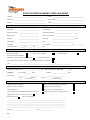
START-UP FORM FOR INDIRECT FIRED LD(E) MODEL
Company:
____________________________________
Project : ___________________________________
Technician :
____________________________________
Project manager :
Installer :
____________________________________
Address :___________________________________
______________________________
Manufacturing informations
Unit model:
_______________________
Serial number:
__________________________
Exhaust fan model:
_______________________
Identification number:
__________________________
Burner model :
_______________________
Burner serial number :
_________________________
Fan type:
_______________________
Surcharge :
_________________________ amps
Motor pulley:
_______________________
Belts :
_________________________
Fan pulley:
_______________________
C-C of pulleys :
_______________________ (+_____ - _____)
Motor information : _________ hp _________ Vac _________ amps
Inspection
Fan rotation verified:
Belts correctly installed:
Air duct installed:
Remote control panel installed :
All ALLEN screws of bearing collar are tighten:
No gas leaks detected:
The joint between the air inlet and the unit is caulked with sealant on top and sides:
Note :
____________________________________________________________________
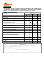
Start-up
Voltage read before the unit:
_____ _____ _____ Vac
Amperage :
1) Low voltage : _____ Amps
Gas pressure :
_________
Electric circuit (low voltage) read:
2) Motor : _____
_________
STOP
HIGH FIRE
|______ ___INLET PRESSURE__ ______|
_________
LOW FIRE
_____ V
_____ _____ Amps
_________
HIGH FIRE
|______MANIFOLD PRESSURE ______|
Various checks
Flame OK low fire (one tube) :
Sufficient air inlet opening for combustion :
Flame OK low fire (all tubes):
Prepurge (30 sec.) delay correct:
Flame OK high fire :
Burner lit in a 7 seconds delay max. :
Logic module program installed and the sequence is correct:
Pressure reading access are closed (gas valve) :
Signal stages control (0-10 volts CC) verified:
Start-up completed:
If not, why (comments):
_______________________________________________________________________________________
_______________________________________________________________________________________
_______________________________________________________________________________________
_______________________________________________________________________________________
_______________________________________________________________________________________
Signature: ___________________________
26
Date: ____________________
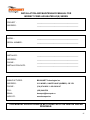
INSTALLATION AND MAINTENANCE MANUAL FOR
INDIRECT FIRED AIR HEATER LD(E) SERIES
PROJECT :
__________________________________________
ADDRESS :
__________________________________________
MODEL :
__________________________________________
SERIAL NUMBER :
__________________________________________
INSTALLER :
__________________________________________
ADDRESS :
__________________________________________
PHONE :
__________________________________________
INSTALLATION DATE:
__________________________________________
MANUFACTURER :
BOUSQUET Technologies inc.
ADDRESS :
2121 NOBEL, SAINTE-JULIE (QUEBEC) J3E 1Z9
PHONE :
(514) 874-9050 / 1-800-363-9197
FAX :
(450) 649-8756
EMAIL:
[email protected]
WEB SITE:
www.bousquet.ca
THIS MANUAL SHOULD ALWAYS BE STORED WITH THE HEATER AND BE
READABLE.
27
Rév.: 24/11/2011
28