1
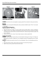
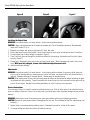
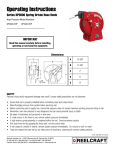
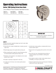
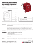
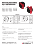
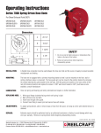
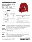
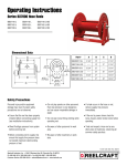
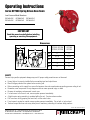
Operating Instructions
Series DP7000 Spring Driven Hose Reels
Low Pressure Model Numbers:
DP7400 OLP
DP7450 OLP
DP7600 OLP
DP7650 OLP
DP7800 OLP
DP7850 OLP
IMPORTANT
Read this manual carefully before installing,
operating or servicing this equipment.
Dimensions
DP7400 / DP7450
DP7600 / DP7650
DP7800
DP7850
A
17”
17”
B
16 1/2”
16 1/2”
C
7”
7”
D
4”
5”
E
8”
9”
SAFETY
Personal injury and/or equipment damage may result if proper safety precautions are not observed.
• Ensure that reel is properly installed before connecting input and output hoses.
• Bleed fluid/gas pressure from system before servicing reel.
• Before connecting reel to supply line, ensure that pressure does not exceed maximum working pressure rating of reel.
• Remember, even low pressure is very dangerous and can cause personal injury or death.
• Be aware of machinery and personnel in work area.
• If a leak occurs in the hose or reel, remove system pressure immediately.
• A high tension spring assembly is contained within the reel. Exercise extreme caution.
• Pull hose from reel by grasping the hose itself, not the control valve.
• If reel ceases to unwind or rewind, remove system pressure immediately. Do not pull or jerk on hose!
• Treat and respect the hose reel as any other piece of machinery, observing all common safety practices.
Form# 1196-1106 Rev: 5/2013
Reelcraft Industries, Inc. • 2842 E Business Hwy 30, Columbia City, IN 46725
Ph: 800-444-3134 / 260-248-8188 • Fax: 800-444-4587 / 260-248-2605
Customer Service: 855-634-9109 • [email protected] • www.reelcraft.com
Series DP7000 Spring Driven Hose Reels
Figure A
Figure B
Figure C
Installation Instructions
WARNING: Ensure that reel, hose, and equipment are properly grounded. Use an ohmmeter to check ground continuity.
Mounting
CAUTION: Unless reel was specified differently when ordering, maximum installation height is 16 feet. Do not exceed
this distance.
Maximum Operating Temperature:
Low pressure (300 p.s.i.) = 150°F (66°C)
1. Unpack and inspect reel for damage. Turn spool by hand to check for smooth operation. Check for completeness.
2. Configure reel for top, side or bottom hose dispensing by removing bolts from one side of the guide roller bracket
and loosening the four guide arm bolts on each side of the hose reel. Remove each guide arm then reinstall in the
desired configuration.
3. Position reel on floor, wall, or ceiling. Secure into place using four (customer supplied) bolts.
Installing the Input Hose
WARNING: Ensure that supply line pressure does not exceed maximum working pressure rating of reel. Apply pipe
thread sealant to all threads on standard reels. Do not overtighten connection. Recommended torque not to exceed
70 ft. lb.
CAUTION: Use flexible hose connection at input. Do not use rigid plumbing. The use of rigid plumbing may void warranty.
1. Apply thread sealant as shown in Figure B and connect input hose to main shaft input Figure C.
2. Tighten securely, ensuring a sealed connection has been made.
Page 2
www.reelcraft.com
Series DP7000 Spring Driven Hose Reels
Figure D
Figure E
Figure F
Installing the Output Hose
WARNING: Use extreme caution; reel under tension. Avoid releasing latch mechanism.
CAUTION: Apply pipe thread sealant to all threads on standard reels. Do not overtighten connection. Recommended
torque not to exceed70 ft. lb.
1.
2.
3.
4.
Manually turn sheave until spring is tight, back off 2 turns, then latch.
Route output hose through roller bracket, U-bolts, then through cut out in spool as indicated in above illustrations.
Connect output hose to swivel output as indicated in Figure E.
Place U-bolt over hose and through the slotted holes below the hose opening. Add washers and lock nuts, tighten
securely. (Figure F)
5. Charge hose. Momentarily open control valve to purge hose of gases. When fluid appears at control valve, close
valve. With hose fully charged, release latch and wind output hose onto reel.
6. Install hose bumper assembly.
Adjustments
WARNING: Use extreme caution; reel under tension. Avoid releasing latch mechanism. If necessary, adjust spring tension on reel by manually adding or removing wraps of hose from spool, one wrap at a time, until desired tension is
obtained. Manually add wraps to increase tension. Remove wraps to decrease tension.
CAUTION: When adding wraps of hose, add just enough wraps to achieve the desired tension without exceeding the winding mechanism’s spring capacity. Properly tensioned reels allow all hose to be freely removed from the spool until the
point of U-bolt contact. Damage to the winding mechanism will result if spring is over-tensioned.
Service Instructions
User servicing of the reel is limited to replacing input/output hoses only. Refer all other repairs to an authorized service
person or directly to Reelcraft. Failure to do so may result in personal injury and/or equipment damage and may void the
warranty.
WARNING: Rewind hose on reel, then bleed pressure from system before performing the following procedures.
CAUTION: Remove all spring tension before disassembling the hose reel. Do not attempt to open the riveted spring case
assembly.
1. Replace hoses in accordance with procedures given in “Installation Instructions” section of this manual.
2. All mating moving parts have been factory lubricated as required.
www.reelcraft.com
Page 3
Series DP7000 Spring Driven Hose Reels
ITEM
NO.
1
3
4
5
6
8
9
10
11
ITEM
NO.
2
7
12
16
19
20
Page 4
PART
NO.
S2-52
S2-51
300006
S602144
300107
261274
261275
S262116
S262110
NO.
REQ’D.
8
4
1
1
4
1
1
1
2
DESCRIPTION
Hex Cap Screw, 5/16-18 x 5/8” Long
Hex Cap Screw, 5/16-18 x 1/2” Long
Set Screw, 3/8-16 x 1/2” Long
Latch Pawl Assembly
Hex Lock Nut, 5/16-18
Spring Arbor
Arbor Key
Hub B
Guide Arm
ITEM
NO.
13
14
15
17
18
21
22
23
PART
NO.
300007
S260031
S262115
S262138
S602149
S76-106
300121
S300011
NO.
REQ’D
2
1
1
1
1
1
1
6
DESCRIPTION
Snap Ring (External)
Spring Case Stud
Hub A
Spring Case O-Ring Seal
Spring Case and Ratchet Ass’y
Hex Jam Nut, 3/8”-24
Set Screw, 3/8”-16 x 3/8” Long
Hex Lock Nut, 10-32
NO.
REQ’D DP7400 OLP DP7450 OLP DP7600 OLP DP7650 OLP DP7800 OLP DP7850 OLP
Guide Roller Bracket Assembly 1
S602143
602143
602143
602143
S602142
S602142
Base Assembly
1
602141
602141
602141
602141
602140
602140
Main Shaft
1
S262120
S262120
S262120
S262120
262119
262119
Drive Spring Assembly
1
S262144-70
262144-50
262145-65
262145-65
262145-65
262145-65
Swivel Assembly
1
602154
602145
602145
602145
602145
602145
Spool Assembly
1
S602147
S602147
S602147
S602147
602146
602146
Hose Assembly
1
None
601070-50
None
601070-50
None
601021-50
Hose Bumper Assembly
1
None
A1-HR1004-A
None
A1-HR1004-3
None
A2-HR1004-3
DESCRIPTION
www.reelcraft.com