1
इंटरनेट
मानक
Disclosure to Promote the Right To Information
Whereas the Parliament of India has set out to provide a practical regime of right to
information for citizens to secure access to information under the control of public authorities,
in order to promote transparency and accountability in the working of every public authority,
and whereas the attached publication of the Bureau of Indian Standards is of particular interest
to the public, particularly disadvantaged communities and those engaged in the pursuit of
education and knowledge, the attached public safety standard is made available to promote the
timely dissemination of this information in an accurate manner to the public.
“जान1 का अ+धकार, जी1 का अ+धकार”
“प0रा1 को छोड न' 5 तरफ”
“The Right to Information, The Right to Live”
“Step Out From the Old to the New”
Mazdoor Kisan Shakti Sangathan
Jawaharlal Nehru
IS 8122-2 (2000): Combine-Harvester-Thresher - Test Code,
Part 2: Performance Test [FAD 21: Farm Implements and
Machinery]
“!ान $ एक न' भारत का +नम-ण”
Satyanarayan Gangaram Pitroda
“Invent a New India Using Knowledge”
“!ान एक ऐसा खजाना > जो कभी च0राया नहB जा सकता ह”
है”
ह
Bhartṛhari—Nītiśatakam
“Knowledge is such a treasure which cannot be stolen”
IS 8122 (Part 2) : 2000
TESTCODE
COMBINE-HARVESTER-THRESHERPART 2 PERFORMANCE
(
TEST
First Revision )
ICS 65.060.50;65.060.99
0 BIS 2000
BUREAU
MANAK
MU)~ 2000
OF
INDIAN
STANDARDS
BHAVAN, 9 BAHADUR
SHAH ZAFAR
NEW DELHI I 10002
MARG
Price Group 12
Farm Implements
and Machinery Sectional Committee, FAD 59
FOREWORD
This Indian Standard ( First Revision) was adopted by the Bureau of Indian Standards, after the draft finalized
by the Farm Implements and Machinery Sectional Committee had been approved by the-Food and Agriculture
Division Council.
Combine-harvester-thresher,
commonly known as-combine, is being increasingly used, for a combination of
operations, such as harvesting, threshing, separating, and cleaning particularly for cereal crops, in the country.
As a result of its increasing
use, the need for standardized
tests for helping the testing institutions for
assessment of the performance of the combine on a uniform and rationalized basis was felt. This test code is
expected to fulfill this long felt need.
This code has been formulated in two parts. While Part 1 of this code covers the terminology, this part (Part 2)
covers the method of various tests to be conducted to assess the performance of the combine including its/prime
mover, in case of self-propelled type combine.
This standard was originally
issued in 1981 and revision has been taken up for the following
a)
To change recommendations
b)
To modify servicing and preliminary
test conditions
about fuels and lubricants
c)
To modify
To incorporate
header lifting/hydraulic
of temperature
e)
To harmonize
parameters.
break performance
f)
To modify data sheets for recording
Rules (CMVR).
g)
To update the standard.
In preparation of this draft considerable
and Testing Institute, Budni.
used during testing of combines.
setting after running-in
d)
reasons :
test.
for laboratory tests.
test and noise level test.
test and air cleaner
oil pull-over test with tractor test for the same
of test data to meet the requirements
assistance
has been derived
of Central Motor Vehicles
from Central Farm Machinery
Training
In reporting the results of a test or analysis made in accordance with this standard, if the final value, observed
or calculated, is to be rounded off, it shall be done in accordance with IS 2 : 1960 ‘Rules for rounding off
numerical values ( r~viscu’)‘. The number of significant places retained in the rounded off value should be the
same as that of the specified value in this standard.
IS 8122 (Part 2) : 2000
Indian Standard
COMBINE-HARVESTER-THRESHER-TEST
PART 2 PERFORMANCE
CODE
TEST
(First Revision)
I SCOPE
4.3 Fuel and Lubricants
1.1 This standard (Part 2) covers the methods
performance
testing of combine-harvester-thresher
(combine).
of
The properties of fuel and lubricant used for test shall
conform to 5.3 of IS 12226.
4.3.1 The oil change-over period as given in the
printed literature shall be followed at the testing
institute.
2 REFERENCES
2.1 The Indian Standards listed in Annex A contain
provisions
which, through reference in this text,
constitute provisions of this standard. At the time of
publication,
the editions indicated were valid. All
standards
are subject to revision and parties to
agreements based on this standard are encouraged
to investigate the possibility of applying the most
recent editions of the standards indicated therein.
4.4 Running-in
4.4.0 The combine shall be run-in at the testing
institute by the applicant in dollaboration
with the
testing institute before the start of the test, under his
responsibility
and in accordance
with his usual
instructions. If this procedure becomes impracticable
for any reasons, the testing institute shall run-in the
combine provided that the authority of the applicant
or his representative, who will remain responsible for
running-in, is obtained.
3 TERMlNOLUGY
3.1 For the purpose of this standard, the definition
of various terms are given in IS 8122 (Part 1) shall
4.4.1 The duration
indicated.
apply.
4 SAMPLING AND GENERAL GUIDELINES
4.1 Specification
4.5 Servicing
Running-in
Sheet
The applicant shall supply the specifications of the
combine consisting of the items listed in the specimen
report given in Annex B as well as any additional
data required to carry outthe tests. The manufacturer
shall also supply literature consisting of operational
and maintenance
manual, service manual and parts
catalogue with the combine. The literature should be
in HindiEnglish.
of running-in
and Preliminary
and place shall Abe
Settings after
4.51
After completion
of running-in
test the
servicing/adjustments
as per printed
literature/
information supplied by the applicant/manufacturer
shall be done. No adjustment shall be made unless it
is recommended in the literature or specific recommendations are submitted before start of test. AH the parts
replaced shall be reported.
NOTE-However,
4.2 Sampling
the adjustment
of fuel in.jection pump
shall not apply to the combine randomly
The combine shall either be selected at random (see
IS 4905) from the production lot by the testing institute
for commercial tests or shall be submitted by the
applicant to the testing authority for confidential/
initial commercial
tests as the case may be. The
combine
selected or submitted
for test shall be
completed
with its usual accessories
and in a
condition generally offered for sale. The combine shall
be new and shall not be given any special treatment
or preparation for test. The method of selection is
given in Annex C.
4.6 Repair and Adjustment
selected for test.
During Test
The applicant during the course of test shall not make
any major adjustment
or introduce
any major
alterations or modifications
which may affect the
normal performance. However, normal operational
adjustments, to suit crop and field conditions or as
conformance to the specifications made available to
the testing authority, can be made during the test. In
case of combine submitted for confidential test, the
testing authority at its discretion can permit major
I
-. _ - ,^,..““._L_..-_~-
-
IS 8122 (Part 2) : 2000
alterations
applicant.
or modifications
on the request
of the
5 TESTS
5.0 The following
conducted.
4.7 Anciltary Equipment
For power tests, all power consuming devices may
be disconnected
only if it is practicable
for the
operator to do so as a normal practice in the work, in
accordance with the operator’s manual and without
using tools, except as otherwise specified for a
particular test. If not, they shall remain connected
and operate at minimum load.
4.8 Fuel Consumption
The fuel measurement
apparatus during laboratory
tests shall be so arranged that the fuel pressure at
the fuel transfer pump of the engine is equivalent to
that which exists when the combine fuel tank is half
full. The fuel temperature shall be comparable to that
in the normal operation of the combine when fuel is
taken from the combine fuel tank.
4.8. I To obtain hourly fuel consumption by volume
and the work performed per unit volume of fuel,
conversion of unit of mass to unit of volume shall be
made using the density value at 15°C.
4.8.2 When the fuel consumption
is measured by
volume, the specific fuel consumption
shall be
calculated using the density corresponding
to the
appropriate fuel temperature.
Conditions
a) Atmospheric Pressure - Minimum 96.6 kPa
during laboratory tests. The pressure shall be
noted at the beginning of the test.
b) Temperature - For power tests, the normal
ambient
temperature
shall be 27 f 7°C.
The temperature for high ambient test shall be
43 * 2°C.
NOTE -
No correction
for atmospheric
4.10 Conditions
shall be made to the test results
conditions.
for Checking of Dimensions
4.10.1 The combine shall be standing~on a firm, level
and horizontal surface.
4.10.2 The combine shall be stationary with its wheels
and components in positions they would be as if the
combine was travelling in a straight line.
4.10.3 The pressure in pneumatic
tyres shall be
ad.justed~to the value recommended by the applicant
for field work. The tyres shall be new. The measurement of height of lugs shall be made at the center line
of tyres.
4.10.4 Measurement conditions for various dimensions and characteristics
as stipulated in IS 8122
(Part I) shall also be followed.
and field tests shall be
5.1 Laboratory Tests
a) Specification checking,
b) Material analysis,
c) Visual observations and checking of provision
for adjustments,
4 Power tests,
e) Hydraulic test,
9 Noise level measurement,
s)
Vibration test,
h) Operator’s field of vision,
.i> Brake test,
k> Air cleaner~oil pull-over test,
m) Turning ability test,
4 Position of center of gravity, and
P) Components/Assembly
inspection.
NOTES
1 Tests indicated at (d), (f), (g) and (k) shall be conducted
in self-propelled
combines only.
2 The laboratory tests shall preferably be conducted prior
to taking up field tests. However, if the necessity arises
the sequence of laboratory and field tests can be changed
by the Testing
4.9 Atmospheric
laboratory
Authorily.
5.2 Field Tests
4 Rate of work and combine capacity
b) Quality of work
i) Efficiencies:
I) Threshing
2) Cleaning
ii) Non-collectable
losses :
1) Pre-harvest
2) Header
3) Rack and shoe
c>Output
i) Straw
ii) Grain
4 Fuel consumption
e) Visual observations
6 LABORATORY TESTS
6.1 Specification
Checking
The specifications
of the combine given by the
applicant ( see 4.2 ) shall be checked and reported in
Annex B by the testing authority. While checking
various dimensions, the conditions stipulated in 4.10
shall be followed.
IS 8122 (Part 2) : 2000
6.2 Material Analysis
The hardness
and chemical
analysis
of critical
components,
such as knife section (see IS 6025)
raspbar, peg tooth, ledger plate and knife guards
(XE IS 6024) shall be made and reported in Annex D.
~6.3 Visual Observations
for Adjustments
and Checking of Provision
The combine shall be subjected to thorough inspection with particular~attention
to bearings, drives and
other moving parts, correctness of various adjustments, tightness of bolts and nuts, etc. The observation given in Annex E shall be recorded.
6.4 Power Tests
6.4.1 The following
tests
IS 12036 shall be conducted:
on the engine
as per
a)
Maximum power (absolute)
IS 12030).
b)
Varying speed test at full load (see 6.1.3 of
IS 12036).
c)
Varying
NOTE-If
recommended
6.4.2
loads test (see 6.1.4 of IS 12036).
the
is different
test (see 6.1.2 of
engine
from
speed
rated
recommended
engine
setting
shall
High Ambient
Test
speed.
also
for
then
field
tests
tests
at the
be conducted.
The following tests on the engine under high ambient
temperature (43 * 2’C) shall be conducted.
6.4.2.1
Vurying speed test
This test shall be carried out in accordance
of IS 12036.
6.4.2.2
with~6.1.3
Five hour engine rating test
engine shall be run at 90 percent
of load
corresponding
to maximum power continuously
for
4 hours. During the fifth hour, the engine shall be run
at a load corresponding
to maximum power. During
the test, all the parameters
specified in 6.1.7 of
IS 12036 shall be recorded after every half-an-hour
during the first 4 hours and after every 1.5 minutes
during the fifth hour.
The
The coolant and lubricating
recorded as under:
a) Coolant-percent
b) Lubricating
oil consumption
shall be
of total coolant capacity, and
oil-glkWh.
b) The ~assemblies/sub-assemblies
other than
hydraulic system shall remain disengaged.
c) The cycle of lifting and lowering shall be kept
continuous. This shall be done for 1 000 times.
d) Before test oil temperature
shall be 65 f 5°C.
The data shall be recorded in F-2.
6.6 Noise Level Measurements
6.6.1 The combine shall be operated at the recommended travel speed at full accelerator with and without
variator. All mechanisms in the combine shall be in
working position. The cutter bar height shall be up to
I50 mm above the ground level.
The noise measurement at by-stander’s position and
drivers ear level shall be conducted in accordance
with IS 12180 and data shall be recorded in proforma
given in Annex G .
6.7 Vibration ~Measurement
6.7.1 The amplitude of mechanical vibration of those
assemblies and components of the combine which
are functionally important shall be measured with the
help of suitable vibration measuring
device. The
combine shall be parked on level concrete surface.
6.7.2 The observations shall be recorded when the
combine sub-assemblies
are operating at no load
engine speed recommended
for field work. The
inflation pressure in the tyres shall be the same as
recommended by the manufacturer for field operation.
The height of cutter bar shall be kept at 150 mm above
ground level.
The maximum horizontal displacement
(HD) and
vertical displacement (VD) due to vibration shall be
measured by mounting the measuring device in related
position and expressed in microns.
6.7.3 The vibration measurement shall be made on
the points and the components given in F-3.
6.8 Operator’s
Field of Vision
This test shall be carried out in accordance
with
IS 11442. During the test the header unit and other
system shall remain attached. The height of cutter
bar above ground level shall be at 150 mm.
6.8.1
The data shall be recorded in F-4.
6.9 Brake Performance
Test
6.5 Header Lifting Test
The cold and hot brake test shall be conducted in
accordance with IS 1206 I in a condition recommended
for road transport.
This test shall be carried out as under:
6.9.1
6.4.3
The data shall be recorded in F-l.
a) The engine speed set at speed recommended
for field operation.
Parking Brake Test
The force, necessary to apply at the control of the
parking braking device to hold the combine harvester
IS 8122 (Part 2) : 2000
NOTES
when facing up and down on 12 percent
recommended
for road
2tyradient in a condition
transport, shall be measured. The maximum actuating
force shall not be more than 400 N for hand operated
and 600 N for foot operated parking brake device.
stationary,
6.9.2
I The period mentioned in (a) and (b) can be reduced
10 percent provided the same is compensated
in (c).
2 As far as possible,
the test in one year.
carried over to the
conditions cannot be
The data shall be recorded in F-5.
minimum
with 8 of
a ) Combine
parked inhorizontal
b) Combine
tilted IO’ to either side, and
level position,
for these two crops
only.
4 Weedy crops on rough hard ground and under
soft ground condition (type of weed and weed
intensity should also be reported);
b) Surfaces have pronounced ridges and furrows
or similar undulations (height of bunds and
ridges, their spacing and size should also be
reported); and
6. IO.I The data shall be recorded in the format given
in Annex D of IS 5994.
6.1 I Turning Ability Test
c>Sloppy
field
5 percent.
The test shall be carried out in accordance
to
IS I 1859. During the test the header unit shall remain
attached and the height of cutter bar above ground
level shall be 150 mm. The data shall be recorded
in F-6.
The data shall be recorded in F-7.
Inspection
The engine, transmission,
brakes, front axle, starter
motor, dynamo and other critical components (chain
sprocket and belts, bearings, hydraulic pumps and
cylinders, wear of rasp bar and peg teeth) as may be
decided by the testing authority, shall be partially
dismantled after conducting all tests including field
tests. The observations listed under 10.1.1 to 10.1.11
of IS 5994 shall be made and reported in the format
given in Annex F of IS 5994.
The combine shall be operated under the prevailing
crop and field condition
preferably
meeting the
requirements of 5.2 of IS 8 I22 (Part 1) for a minimum
of 200 hours for the following crops:
IOOh
a) Wheat harvesting
50 h
of
7.3.1 The pre-harvest losses shall be determined, at
three places randomly
selected within the area
selected, for test run of at least I5 m. The area from
where the sample is to be collected shall preferably
be I m in direction of travel and full or half width of
cutter bar of the machine depending upon its size.
All the loose grains, complete
and incomplete
earheads fallen in the marked area before the machine
has run over it shall be picked up manually without
undue vibrating the plants and analyzed for determining the pre-harvest losses in kg/ha.
7.1 Field and Crop Conditions
50 h
slope
7.3 Field Operation
7 FIELD TESTS
b) Paddy harvesting
a maximum
The combine shall be operated by an experienced
operator. The applicant or his representative
shall
demonstrate
the operation of the combine to the
testing authority in actual field condition. The testing
shall not be carried out until the testing authority is
satisfied that the machine is operating correctly.
Before starting the test, the combine shall be adjusted
as per manufacturer’s
recommendations.
This
adjustment may be modified to obtain the highest
possible output consistent with percentage of losses
regarded as reasonable by the testing authority and
the applicant’s representative.
Performance
values
obtained during preliminary adjustment need not be
reported. The combine may be adjusted for operational
adjustments between successive test runs in order to
maintain optimum performance at varying speeds.
Manufacturer’s recommendations
for various adjustment shall be followed. Some recommendations
for
better performance are given in Annex H .
The test shall be conducted
in accordance
with
IS 10743. However. during the test the grain tank(s)
shall be fully tilled with grain, header assembly fully
raised and the reel adjusted in its most forward
position.
c) Other crops recommended
for combining by the applicant
having
7.2 General Condition for Operation
6.12 Position of Centre of Gravity
6.13 Components/Assembly
of 200 hours
7.1.1 In addition, combining shall also be carried out
under following conditions, if exist in the field:
c) Combine tilted IO” to forward and backward
in relation to the direction of travel of the
combine.
6.12.1
attempts should be made to complete
However part of work/test
may be
following
year if required
range of
obtained in a single season.
3 In case the combine is meant for only two crops, such
as wheat and paddy, the total period of operation shall be
6. IO Air Cleaner Oil Pull-Over Test
The test shall be carried out in accordance
IS 599-l in following conditions:
by
4
IS 8122 (Part 2) : 2000
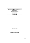
7.3.2 For determining rack and shoe loss, the~straw
and chaff afflux is collected separately. To collect the
straw and chaff leaving the machine, two rolls of cloth
(preferably 1.5 times the width of straw/chaff outlet)
are suspended on especially attached fittings beneath
the rear of the machine, so that as it unrolls, one
cloth sheet catches the afflux from the straw walker
and the other from the sieve. Each cloth sheet is 30 m
in length. The test run shall not be less than 15 m in
length. The unrolling operation of the sheet should
start in advance by 5 m distance behind the starting
point of the test run. The unrolling of sheets shall
terminate after the combine has passed over 5 metres
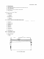
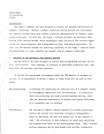
ahead to the end point of the test run (see Fig. 1).
7.3.2.1 Signals shall be given at the start and at the
end of the test run to determine the time taken by the
machine to cover the test run and for collection of
grain at the main outlet and secondary outlet. The
straw and chaff for Ihe test run shall be collected
from the sheets and rest of the material discarded.
7.3.3 The header loss shall be determined on those
portion of the ground which are protected from
combine afflux by the use of rolls of cloth or sheet.
The loose grains, and complete and incomplete
earheads fallen on the marked area, where the preharvest losses were determined, shall be picked-up
manually and represented as a percentage of grain
throughput to the combine.
7.3.3.1 Care should be taken that no material falls
down from the combine over marked areas. The header
loss like pre-harvest loss shall be determined at three
places and average of the observations
shall be
reported.
7.3.4 The combine should be operated for at least
10 m before recording the data to ensure that the
crop and the grain circuits and the cleaning systems
have been filled. The combine should be operated at
a uniform speed and in such a manner as to use its
full cutting width. As far as possible, a constant
stubble height shall be maintained.
7.3.4.1 In each-field the test shall be carried out at
the same forward speed as used in the preliminary
adjustment.
7.3.4.2 No change in the forward speed adjusted
before the test and any stoppage during the test run
shall be permitted. If this happens because of some
unavoidable circumstances the test observations shall
be repeated.
7.3.4.3 During and after the test run, the observations
shall be recorded in Annex J. Three samples from the,
grain tank (main outlet) and complete sample for the
run from straw walker and sieve shall also be collected.
7.3.4.4 The moisture content of the grain sample
obtained from grain tank (main outlet) and straw
(standing crop) shall be determined. The samples
collected from grain tank, straw walker and sieve shall
be analyzed for the following and data recorded in
data sheet given in Annex K .
a)
b)
c)
d)
Clean grain,
Foreign matter,
Unthreshed grain, and
Damaged grain.
7.3.4.5 From the observations made under 7.3.4.3
and 7.3.4.4, the following shall be calculated and the
data recorded in Annex K.
FIG. 1 COLLECTION
OF STRAWOVERCLOTHROLLSON COMBINES
IS 8122 (Part 2) : 2000
a>Rate
c>Time
of work in ha/h;
lost in turning (this may be recorded for
at least one hour operation);
b) Net grain output kg/h and kg/ha;
c> Grain
4 Time required to fill the grain tank;
4 Time required to empty the grain tank;
4 Fuel consumed;
4
g) Lubricating oil consumed;
h) Coolant (water) consumed;
3 Operating speed;
throughput (net grain output + header
loss + rack loss + shoe loss) in kg/h and kg/
ha;
Straw output in kg/h and kg/ha;
e) Losses expressed
as percentage
of grain
throughput:
~4 Average working width;
m) Time for any stoppage;
n) Accessibility of controls;
9 Header loss,
ii) Cylinder
loss,
iii) Sieve loss,
iv) Secondary
P) No load and on load engine speed; and
9) Maximum temperature of engine oil/coolant,
and ambient.
sieve loss (if applicable),
Straw walker loss, and
v)
vi) Grain breakage.
6 Cleaning efficiency, percent;
S> Threshing efficiency, percent; and
h) Combine capacity (gross grain output and
straw output), t/h.
NOTES
1 A minimum
of three
tests may be conducted
on a
particular
variety
of the crop and the average
of these
observations
shall give the representative
figure
of the
combine
2 The
7.4.2.1
losses
may
The
noncollectable
be grouped
definitions
loss shall
pre-harvest
as collectable
of
collectable
he as given
losses
shall
in IS 8122
be reported
and
non-
loss
and
(Part
separately
7.4.2.2
of
IS
combine
8122
The
range
conducting
far
7.3.4.6
(Part
capacity
I)
shall
as stipulated
against
be determined
of combine
capacity
three tests with three
and
I).
in
5.2.1.1
reported.
shall
be declared
by
varieties
of the crop as
7.4.2.3
as possible.
Night observations
Ease of operation and handling
Safety provisions
The note on safety device, such as slip clutches,
shear pin, signal horns, indicator lights, provided for
various systems shall be taken. The provision of stone
trap, spark arrester and any other safety feature shall
also be checked and reported.
Test under difficult conditions
If facilities exist, combine shall be operated in at least
one test run under the conditions given in 7.1.1.
7.4 The combine shall be operated continuously for
a minimum of IO h duration. The behaviour of various
functional
components
of the combine shall be
recorded.
7.4.1
During and after the operation,
observations shall be recorded:
shall also
Observations shall be made on skill and intensity of
effort required to operate various controls of the
machine. Adequacy of accessibility of controls and
visibility of the header and instrumentation
shall
also be recorded. The note on operator’s working
condition, the ease of setting adjustment,
routine
maintenance and other similar features shall also be
made.
ligiha.
4 The
observations
A night trial lasting for minimum of two hours shall
be conducted to assess the intensity and suitability
of the lighting equipment for the night work.
losses.
collectable.
3 The
7.4.2 Following additional
be made and recorded.
7.4.2.4
Soundness
of construction
Observations shall be made of these features which
adversely affect the operation and efficiency
of
machine in the field. All the breakdowns and defects
occurring during the course of field evaluation period
shall be recorded. The modification which could bring
about improvement in the quality of rate of work shall
also be noted.
following
a) Area covered;
b) Time of operation;
6
IS 8122 (Part 2) : 2000
ANNEX A
( Clause 2 )
LIST OF REFERRED INDIAN STANDARDS
IS No.
Title
IS No.
5994: 1998
Test code for agricultural
tractors (second revision)
6024 : 1983
Guards
harvesting
revision)
(fingers)
machines
for
(first
Title
11442: 1996
Method of tests for operator’s
field of vision for agricultural
tractors
11859 : 1986
Method for determination
of
turning and clearance diameter
of agricultural tractors
6025 : 1982
Knife sections for harvesting
machines (first revision)
12036 : 1995
8122
(Part I) : 1994
Test
code
for
combine
harvester-thresher
: Part I
Terminology (first revision)
Method of test for power takeoff and belt pulley performance of agricultural tractor
12061 : 1994
8132 : 1999
Tractors and machinery
for
agriculture
and forestryOperator’s manual--Content
and
presentation
(first
revision)
Test~code for method for braking performance
test for
agricultural tractors
12180 : 1987
Method for noise
ment of agricultural
12226 : I995
Agricultural
tractors-Power
tests for drawbar-Test
procedure first revision)
I0743 : 1983
Method for determination
of
center of gravity on agricultural tractors
ANNEX B
( Clauses 4.1 and 6.1 )
SPEClFlCATION
B-l
B-2
SHEET FOR COMBINE HARVESTER
GENERAL
a)
Name and address of’ manufacturer
b)
Make
c)
Model
d)
Type
e)
Year of manufacture
f)
Serial number
PRIME MOVER
B-2.1 General
a)
Make
b)
Model
c)
d)
Type
Serial number
e)
Engine speed (Manufacturer’s
I)
Maximum
recommended
setting) (rpm)
speed at no load
7
measuretractors
IS 8122 (Part 2) : 2000
2) Rated speed
3) Low idle speed
f)
Location
g)
Mounting
B-2.2 Cylinder and Cylinder Head
a)
Number
b)
Disposition
c)
Bore/Stroke (mm)
d)
Capacity
e)
Compression
t)
Type of cylinder
head
g)
Type of cylinder
liners
h)
Arrangement
j)
Type of cumbustion
k)
Valve clearance in cold/hot (mm)
as specified by the applicant
(cu.cm)
ratio
of valves
chamber
1) Inlet valve
2)
B-2.3
Exhaust valve
Fuel System
B-2.3.1
Type of Fuel System
B-2.3.2
Fuel Tank
a)
Capacity (I)
b)
Location
c)
Provision
B-2.3.3
for draining
of sediments/water
Fuel Feed Pump
4
b)
Type
Make
c)
Mode1
d)
Provision
B-2.3.4
of sediment bowl
Fuel Filters
a)
Make
b)
Mode1
c)
Number
d)
Type of elements
e)
Capacity of final stage filter (1)
B-2.3.5
Injection Pump
a)
Make
b)
Model
c) Type
d) SlNo.
e)
B-2.3.6
Method of drive
Fuel Injectors
a)
Make
b)
Model
8
IS 8122 (Part 2) : 2000
cl Type
d)
Manufacturer’s
e)
ln.jection timing
t)
Firing order
production
pressure setting, MPa
B-2.4 Governor
a)
Make
b)
Model
c)
Type
d)
Governed
e)
Rated engine speed (rpm)
range of engine speed (rpm)
B-2.5 Pre-cleaner
a)
Make
b)
Type
c)
Number
d)
Location
e)
Height of pre-cleaner
top above ground level (mm)
B-2.6 Ai; Cleaner
Make
4
13) Type
cl Number
Location
4
e) Size of dry filter element IDiODiLength
9 Range of suction pressure, kPa (mm of Hg)
g1 Oil capacity (I)
11) Oil change period
B-2.7 Exhaust
a)
Type of silencer
b) Position of silencer outlet
c)
Range of exhaust gas pressure kPa (mm of Hg)
d)
Provision
B-2.8 Lubricating
B-2.8.1
Tvpe
B-2.8.2
Filters
a)
Type
of spark arresting device
System
b) Number
c) Oil sump capacity (I)
4
B-2.8.3
Oil change period
PW?Zp
a) Type
b) Method of drive
c)
Pressure release setting kPa (kgf/sq.cm)
4
Minimum
e)
Method of oil cooling
permissible
pressure, kPa (kgf/sq.cm)
9
IS 8122 (Part 2) : 2000
B-2.9 Detailsof
a)
Type
b)
Make
c)
Model
Heat Exchanger
d) Number
of tubes
e)
Size of tube (mm)
f)
Capacity (I)
1) Oil
2) Water
B-2.10 Cooling System
B-2.10.1
4
Type
b)
Details of pump
c)
Details of fan
d)
Means of temperature
B-2.10.2
control
Radiator
a)
Effective size of radiator (mm):
b)
Number
c)
Type of radiator grill
d)
Means of grill cleaning
e)
Method of mounting
f)
Type of radiator cap
g)
Radiator cap pressure kPa (kgf/sq.cm)
of tubes
h)
Bare radiator capacity (I)
j)
Total coolant capacity (1)
B-2.1 I Starting System
4 Type
b) Aid for cold starting
c)
B-2.12
Any other device provided
for easy starting
Electrical System
B-2.12.1
a)
Batrery
Make
b) Number
c)
Capacity
d)
Location
B-2.12.2
Make
b)
Model
c) Type
d) Capacity
a)
and rating
Starter
a)
B-2.12.3
and type
and rating
Alternator
Make
10
IS 8122 (Part 2) : 2000
b)
Model
c) Type
d) Output rating
e)
Location
0
Method of drive
B-2.12.4
Voltage Regulator
a)
Make
b)
Type
c)
Capacity
B-2.12.5
Detail offights
Number and
capacity of bulb
Description
Head lights
Front working
Centre
light
working
Front side
light
light
Front side indicator
light
Tail light-cum-brake
Rear side indicator
light
light
for unloading
Rear work light
Engine inspection
Side inspection
light
light
Flasher light (Red)
Dash board light
Trailer light:
a)
Parking-cumbrake
b)
Side indicator
light
Main switch details
Light switch details
B-2.12.6
Horn
a)
Make
b)
Type
c)
Location
B-2.12.7
Fltse Box
B-2.12.8
Dctcril.7 qf Other Electrical Accessories
B-2.13
Operational
Mass of Primemover
B-3 COMBINE
B-3.1 Wheel Equipments
(kg)
Height
above ground
to the centre
beam (mm)
Size
of beam
G-w
Distance
from centre of
the beam to
outside edge of
combine (mm)
IS 8122 (Part 2) : 2000
B-3.1.1
Driving
a)
Make
b)
Type
c)
Location
d) Number
Wheels
and size
e)
Track width (mm)
f)
Recommended
B-3. I .2 Steering
a)
Make
b)
Type
c)
Location
tyre pressure, kPa
Wheel
d) Number and size
e)
Track width (mm)
f)
Recommended
tyre pressure, kPa
B-3. I .3 Wheel Base (mm)
B-3.2 Transmission
B-3.2.1
System
Cfutch
a)
Make
b)
Type
c)
Size(mm)
d) Number of friction discs
e)
Location
f)
Method of operation
B-3.2.2
Geur Box and D@crential
a)
Make
b)
Type
c)
Location
d) Number
of speed
e)
Method of drive
t)
Method of gear shifting
g)
Oil capacity (1)
h)
Oil changing
B-3.2.3
Final Drive
period
a)
Type
b)
Reduction
c)
Location
d)
Oil capacity (I)
e)
Oil changing
ratio
period
12
IS 8122 (Part 2) : 2000
B-3.2.4
Nominul
Speed
Gear
No.
Movement
No. of engine
revolutions for
one revolution
of driving
wheel
Without Variator:
1
Forward
2
3
R
Reverse:
With Variator.
I
Forward
2
3
R
Reverse
B-3.3
Brakes
B-3.3. I Service
Brukr
Make
4
b) Type
c) Location
Area of liners (sq.cm)
4
e) Thickness of liner (mm)
r) Method of operation
Parking
B-3.3.2
Brake
Make
a)
b) Type and location
c) Method of operation
B-3.4
Steering
System
a)
Make amd model
b)
c)
Type
Method of operation
d)
Diameter of steering control wheel (mm)
e)
Location
B-3.5 Hydraulic
System
B-3.5.1 Pump
a)
Type
b) Make
c)
Model
d) Number
e) Method of operation
t)
Location
13
Nominal speed at rated engine
speed when fitted with
size tyre at an inflation
pressure of ~
kPa and rolling
radius of
mm (kmph)
IS 8122 (Part 2) : 2000
B-3.5.2
Hydruulic
Tank
4
b)
Type
Location
c)
Size(mm)
d)
Capacity (1)
e)
Oil change period (h)
f)
Number
B-3.5.3
B-3.6
and type of oil filters
Number of Hydraulic
Cylinders
Reel Assembly
a) Type
b) Number
of tyne bars
c)
Size of tyne bars (mm)
d)
Type of tyne bar
e)
Dia of reel (mm)
t)
Width of reel (mm)
g)
Range of speed corresponding
h)
Arrangement
j)
Number
k)
Maximum
to rated engine speed for field work (rpm)
for speed variation
of tynes on each bar and their spacing
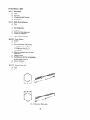
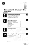
distance ahead of cutter bar points (mm) (see A in Fig. 2)
m) Maximum
distance
behind the cutter bar points (mm) (see B in Fig. 2)
n)
Maximum
vertical distance below the cutter bar points (mm) (see C in Fig. 2)
p)
Maximum
vertical distance above the cutter bar points from the centre of reel (mm) (see D in Fig. 2)
q)
Distance from cutter bar points to the front of feeding auger (mm) ( see E in Fig. 2)
r)
Arrangement
for raising and lowering the reel
s)
Arrangement
for forward and backward movement
t)
Arrangement
for variation
of reel
of angle of the tyne
u) Type of reel drive
v) Safety device in reel drive
B-3.7 Cutter
a)
Bar Assembly
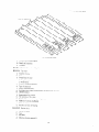
Working width (mm) (see T, in Fig. 3):
b)
Effective cutter bar width (mm) (See T, in Fig. 3)
c)
Number and spacing of knife guards ( see R in Fig. 3):
d) Number
and type of knife blades
e)
Details of knife drive
f)
Knife safety arrangement
FIG. 2 REEL ASSEMBLY
14
IS 8122 (Part 2) : 2000
8) Knife stroke (mm)
h) Strokes per minute
3
Knife speed corresponding
k>
4 Arrangement
to rated engine speed for field-work
(rpm)
Type of ledger plate
n>Type
and range of adjusting
cutting heights
of dividers
P) Arrangement
for lifting lodged crop
B-3.8 Hardness of Knife Blades (HRC)
a)
Hardened
zone
I)
Minimum
2)
Maximum
b) Remainder
zone
I)
Minimum
2)
Maximum
B-3.9 Chemical Composition
of Knife Blade and Knife Guards
K&e
4 Carbon (%)
b) Manganese (%)
c>Phosphorus
4
e>Silicon
9
S)
h)
j>
k>
B-3.10
a)
(%)
Sulphur (%)
(%)
Copper (%)
Nickel (%)
Chromium (%)
Tin (%)
Molybdenum
(%)
Cutting PIatform Auger
Type of crop conveyor
b) Size of auger (mm)
1) Dia
2) Width
FIG.3 CUTTER
BARASSEMBLY
15
Blade
Knife Guards
IS 8122 (Part 2) : 2000
c)
Speed of the auger corresponding
d)
Details of retractable
to rated engine speed for field work (rpm):
fingers
1) Number
2) Range of throw out (mm)
3) Axial spacing between the fingers (mm)
4) Peripheral
distance between the fingers (mm)
5) Arrangement
for adjustment
e)
Arrangement
for adjusting
f)
Auger drive safety arrangement
of fingers
the clearance
of crop auger
B-3.1 1
Height of Header Assembly in the Transport Position (mm)
B-3.12
Arrangement
for Locking the Header Assembly in Raised Position
B-3.13
Arrangement
for Side Way Tilting the Header Assembly
B-3.14
Undershot Conveyor
a)
Type of feeder conveyor
b) Number
and type of chains
c)
Number of combs
d)
Size of combs (mm)
e)
Size of chain (mm)
t)
Roller dia (mm)
g)
Pitch (mm)
h)
Spacing of combs (mm)
j)
Width of conveyor (mm)
k)
Conveyor
drive safety arrangement
m) Arrangement
for adjusting
clearance between comb and platform
n)
Speed of conveyor
p)
Number of teeth on comb bar
B-3.15
Threshing
corresponding
to rated engine speed for field work (rpm)
Drum
Raspbar Type
a) Type
b) Width (mm)
c)
Outside dia (mm) (see D in Fig. 4)
d)
Range of speed corresponding to rated
engine speed for field work (mm)
1) Minimum
2) Maximum
e)
Peripheral
I)
2)
f)
speed (misec)
Minimum
Maximum
Number
of bars
g) Number
of hub plate(s)
of pegs and their spacing on each bar
h)
Number
j)
Height of pegs (mm)
k)
Length of raspbar (mm)
m) Number of rasps/l 00 mm
n) Number of rasps on each bar
p) Number
and type of bearings
q)
Arrangement
r)
Hardness (HRC)
of bars
16
Pegtooth
Type
IS 8122 (Part 2) : 2000
I) Minimum
2) Maximum
s)
Chemical composition
I) Carbon (%)
2) Manganese
(%)
3) Silicon (%)
4) Phosphorus
(D/O)
5) Sulphur (%)
6) Molybdenum
(%)
7) Chromium (%)
8) Nickel (%)
9) Copper (%).
10) Tin (“5)
1I) Aluminium
t)
B-3.16
(%)
Method of speed variation
Ruspbar Type
Concave
a) Width of concave (mm)
b)
Effective width (mm)
c) Type of concave
d) Number
of bars
e) Number
of pegs per bars
t) Height/spacing
of the pegs (mm)
g)
Peripheral length (mm)
h)
Effective area (sqm)
j) Additional
area of extension
(sq.m)
k) Details of extension
m) Range of clearance (mm)
I)
2)
n)
Front (XX, E! in Fig. 4)
Rear (see E ir, Fig. 4)
Method of adjusting
drum and concave
the clearance
between
FIG. 4 DRUM ASSEMBLY
17
Pegtooth
Type
IS 8122 (Part 2) : 2000
B-3.17
Rear Beater
a)
b)
Type
Size(mm)
c)
Arrangement
d)
Type of drive
B-3.18
and location
Baffle Plate (Deflector)
a) Type
b) Number of flaps
c)
Size of flap (mm)
d)
Location
e)
Method of flap adjustment
f)
Method of fixing flap
B-3.19
B-3.19.1
Separating Mechanism
Straw Walkers
a)
Number
b)
c)
Type
Size of each straw walker (mm)
I) Length (see P in Fig. 5)
2) Width (see R in Fig. 5)
d)
e)
f)
3) Area (m* )
Effective separating
walker (m’ )
Lift/throw (mm)
area of straw
Oscillation per minute corresponding
to field speed of engine
g)
Type of extension
h)
Number and type of bearing
B-3.19.2
4
b)
Stepped Grain Pan
Type
Size (mm)
FIG.5 SEPARATING
MECHANISM
18
IS 8122(Part2):2000
FIG. 6 CLEANINGSIEVE
c) Effective area of pan (sq.m)
4 Details of extension
e) Location
B-3.19.3
~‘lcunin~y Sicw.s
( see Fig. 6)
B-3.19.3. I Top .sicvc
a) Number of sieve
b) Type
Overall size of sieve
I) Length (mm)
3-) Width (mm)
Effective cleaning area (m2 )
Type of extension
Area of extension
(m2 )
Oscillation per minute corresponding
Lift/throw (mm)
Arrangement
for varying
The opening
of the sieve
to field speed of engine
Height of lips at maximum opening (mm)
Method of varying
oscillation
Method of drive
Number
a) Number
and type of bearing
of sieve
b) Type
c)
Size (mm)
d)
Effective cleaning area (m2)
19
IS 8122 (Part 2) : 2000
e)
Size of hole (mm)
f) Spacing of hole
g)
Oscillations per minute corresponding
rated engine speed
h)
Method
j)
Height of lips at maximum
of varying
k) Arrangement
to
oscillations
opening (mm)
for varying
the opening
sieve
m) Density of holes/l 00 mm2
B-3.19.3.3
a)
Blower
Dia(mm)
b)
Effective width (mm)
c)
Number
d)
Size of blade (mm)
and type of blade
1) Length
2)
Width
e)
Type of drive
f)
Method
g)
Speed corresponding
of varying
the blower speed
to rated engine speed for field work @pm)
1) Minimum
2)
h)
Maximum
Method
B-3.19.3.4
of controlling
Grain pan
4
b)
Type
Size(mm)
c)
Inclination
d)
Location
B-3.20
the air blast
Grain Conveying Mechanism
B-3.20.1
4
b)
Bottom Grain Conveyor
Type
Length of conveyor
(mm)
c) Outer dia of auger (mm)
d)
Pitch of conveyor
e)
Speed corresponding
f) Number
Method of drive
h)
For safety device
4
b)
to field speed of engine (rpm)
and type of bearings
g)
B-3.20.2
screw (mm)
Grain Elevator
Type
Length of elevator (mm)
c) Outside section (mm)
d) Number
e)
and type of pad
Size of pads (mm)
f) Spacing of pads (mm)
g) Speed corresponding
to field speed of engine (rpm)
h) Type and size of chain (mm)
j)
Elevator drive safety arrangement
k) Method
of tensioning
the chain
20
IS 8122 (Part 2) : 2000
B-3.20.3
Upper Grain Auger
a) ‘We
b) Length (mm)
c) Dia(mm)
d)
Pitch of conveyor
screw (mm)
e) Speed corresponding
to field speed of engine (rpm)
f) Type of drive
g)
Safety arrangement
B-3.21 Tailing Conveying
B-3.21.1
Mechanism
Bottom Tailing Auger
a) Type
b) Dia(mm)
c) Length of auger (mm)
d) Pitch of~conveyor screw (mm)
e) Speed corresponding
to field speed of engine (rpm)
t) Type of drive
g) Number
B-3.2 I .2
and type of bearing safety device
Tailing Elcvtrtot
a) Type
b) Length of elevator (mm)
c) Outer section (mm)
d) Number
and type of pads
e) Size of pads (mm)
f) Spacing of pads (mm)
g) Type and size of chain (mm)
h) Method of tensioning
j)
the chain
Elevator drive safety arrangement
B-3.22 Grain Tank
B-3.22.1 Gcncrul
a) Location
b) Capacity
I)
Volume basis (cu.m)
2) Mass basis (kg)
c) Method of agitating the grains in tank
d)
B-3.22.2
Size of grain tank opening (mm)
Gruin Convq~ing Auger (Bottom of Grain Tank)
a) Type
b)
Dia (mm)
c) Pitch of screw (mm)
d)
Length of screw (mm)
e) Speed corresponding
to field speed of engine (rpm)
t) Number and type of bearing
g) Type of drive
B-3.22.3
Gmin
Unlorrdirlg Auger
a) Type
b)
Dia of auger (mm)
c) Pitch of screw (mm)
d)
Length of unloading
auger (mm)
21
IS 8122 (Part 2) : 2000
e)
Horizontal reach (mm)
f) Discharge height above ground level (mm)
g) Clearance height (mm)
h)
Speed corresponding
to field speed of engine (rpm)
j) Type of drive
k) Safety device
B-4
SAFETY DEVICES PROVlDED ON THE MACHINE
a)
b)
c)
etc
B-5
OPERATING CONTROLS, GAUGES AND INSTRUMENTS
B-5.1 On the Panel Board
a)
b)
c)
etc
B-5.2 Controls on RHS of the Operator
a)
b)
c)
etc
B-5.3 Controls on LHS of the Operator
a)
b)
c)
etc
B-6 OPERATOR’S
a)
THIN SEAT
Make
b) Type
c) Type of suspension
d) Type of dampening
e) Longitudinal
adjustment
f) Adjustment
oi back rest
B-7 HELPER’S
(mm)
SEAT
a) Make
b) Type
c) Ad.justments
d)
Location
B-S CANOPY
;I) Type
b)
Size (mm)
c) Height from operator‘s platform (mm)
B-9 OVER4LL
DIMENSIONS OF COMBINE HARVESTER IN WORKING POSITION (mm)
a) Length
b) Width
c) Height
22
IS 8122 (Part 2) : 2000
B-10 MASSES
Mass of combine harvester with coolant, fuel,
lubricants and grain tank full and 75 kg mass on the the operator’s
a)
Total
b)
Front
c)
Rear
seat (kg)
B-11 MINIMUM GROUND CLEARANCE (mm)
B-l 2 TOTAL NUMBER OF LUBRICATING POINTS
a)
Greasing
b)
Oiling
B-l 3 COLOUR OF COMBINE
B-l 4 HEADER TRANSPORT TRAILER
a)
b)
Type
Number
c)
Make
d)
e)
Size(mm)
Track width (mm)
t)
Height of hitch in working position (mm)
and type of wheels
g)
Minimum ground clearance (mm)
h)
Transport
j)
Overall dimensions
length of combine with header assembly on trailer (mm)
(mm)
I) Length
2) Width
3) Height
B-I 5 DETAILS OF STANDARD ACCESSORIES AVAILABLE WITH THE COMBINE
B-15.1 Standard Accessories
B-15.2
Optional
Accessories
23
IS 8122 (Part 2) : 2000
ANNEX
C
(Clause 4.2)
RANDOM SELECTION
C-l DATE-OF
OF COMBINE
HARVESTER
FOR COMMERCIAL
TESTTNG
SELECTION
PLACE
c-2
c-3 SELECTEDBY
c-4 DESIGNATION
C-S
Combine
selected
Nos.
out of ____
of Combine
Harvesters
bearing
SI No.
C-6
OBSERVATION
Sl
ON COMBINE
HARVESTER
SELECTED
Make
C’olll/mcnt
Model/
Size
h.0.
I.
Combine
7
-.
Engine
3.
F.1. pump
4.
Governor
_5
Gear box
6.
Hydraulic
7.
Self
8.
Generator/alternator
9.
Front
10.
Serial
No.
harvester
pump
starter
tyres
i)
L.H.
ii)
R.H.
Rear Tyres
I I.
i)
L&f.
ii)
f1.f I
Trailer
tyres
L.f I.
i)
ri.fi.
I:.ti~inchour
ii)
12.
C-7 COMBINE
meter
reading
HARVESTER
1)
Tappet
3
FIIL’I ili.jection
i)
f-,.1.
4)
fn_jectors
5)
r:n$ne
sump
6)
P~igine
bell
7)
Slal-tcr
S!
I)) iiamo
0)
I l!draulic
:
_ h.
ASSEMBLY
TO BE SEALED
Yes/No
cover
pump
coupling,
Pwnp and governor
mounting
bolts
Yes/No
Yes/No
screw
Yes/No
Yes&Jo
Yes/No
housings>
Yes/No
lllotol
Yes/No
pump
IO)
(icat- box front
11)
FinnI drive
Yes/No
- Nos. (One/Two)
Yes/No
cover
asscmbl~,
LfHSand
Yes/No
RHS
24
IS 8122 (Part 2) : 2000
Yes/No
12)
Rear wheel axle
13)
Reel
14)
Blade ball strap
Yes/No
15)
Crop auger
Yes/No
16)
Feeder conveyor
17)
Threshing
18)
Blower assembly
Yes/No
19)
Grain auger mechanism
Yes/No
20)
Sieve oscillating
Yes/No
21)
Straw walker crank mechanism
Yes/No
22)
Tailing auger mechanism
Yes/No
23)
Grain elevator
Yes/No
24)
Tailing elevator
Yes/No
25)
Bevel crank mechanism
Yes/No
26)
Any other component/assembly
Yes/No
Yes/No
support
Yes/No
assembly
Yes/No
drum shaft
mechanism
(Please specify)
ANNEX D
(Clause 6.2)
DATA SHEET FOR MATERIAL OF CONSTRUCTION
qf
Elements
C’omposition
Carbon
Kn$z
Ledger Plate/
Section
Guurd
Threshing
Rasp Bar
Cylinder
Peg Tooth
(%)
Manganese
(%)
Phosphorus
(%)
Sulphur
(%)
Silicon (943)
Copper
Nickle
(‘?4)
(%)
Chromium
(%)
Vanadium
(%)
Molybdenum
(%)
ANNEX
E
( Clause 6.3 )
DATA SHEET FOR VISUAL OBSERVATIONS
E-l
OB,SERVATIONS
.
a)
Adequacy of marking
of inlets and outlets
b)
Adequacy
of marking
of rotation of threshing
c)
Adequacy
of protection
d)
Adequacy
of safety arrangements,
e)
Provision
of lubrication
AND PROVISION
units
of bearing against the ingress of dust
specially
at moving
of moving parts
2s
points
FOR ADJUSTMENTS
IS 8122 (Part 2) : 2000
f)
Provision
for easy changing
g)
Provision
for easy replacement
h)
Yielding of seams
j)
Tightness
of bolts and nuts and other fasteners
k)
Provision
of belt tightening
m)
Other observations
E-2 PROVISION
Concave
b)
Speeds for
c)
requiring
frequent replacement
and cleaning of screens
FOR ADJUSTMENTS
a)
i)
ii)
iii)
iv)
v)
vi)
vii)
viii)
of components
clearance
Reel
Feed auger
Threshing drum
Blower
Separating unit
Cleaning unit
Grain discharge auger
Grain elevator
Screen slope
d)
Sieve opening
e)
Air displacement
f)
Wind deflector
Testing Engineer
ANNEX
F
(CZauses 6.4.3, 6.5, 6.7.3, 6.8.1,6.9.2,
DATA SHEET FOR LABORATORY
F-l
6.11 and6.12.1)
TESTS
POWER TEST
a> Date
and place of test
b) Type of dynamometer
c> Fuel
i)
ii)
4
used
used:
Type
Density at 15°C
Engine oil used:
i)
ii)
Type
Grade
e> Transmission
oil used
t) No load maximum engine speed, revimin
g> Engine oil consumption during rating test in kg/h under high ambient conditions
h) Engine performance test data sheet given in F-8
F-2 HEADER
LIFTING
TEST
a)
Date of test
b)
Make and model of combine
c)
Engine speed corresponding
to field speed (rpm)
26
IS 8122 (Part 2) : 2000
d)
Operating
e)
Temperature
f)
Hydraulic
g)
Abnormality,
oh)
Any other
F-3 VlBRATlON
condition
of hydraulic
fluid after each 100 cycle
oil leakage from any point
if any
MEASUREMENT
a)
Date and location
of test
b)
Type of accelerometer
c)
Test data :
Measuring
Sl
No.
Vibration, Microns
Combine Parked
Points
HD
9
Foot rest, left
ii)
Foot rest, right
iii)
Gear shifting lever
iv)
Cutting
unit engaging
v)
Brake pedal, left
vi)
Brake pedal, right
vii)
Hydraulic
viii)
Clutch pedal
lever for platform
9
Steering control wheel
x)
Seat back, bottom
xi)
Accelerator
xii)
Threshing
xiii)
Threshing
xiv)
Cylinder
xv)
Unloading
lever
level
and clearing
unit engaging
drum speed changing
concave clearance
auger engaging
lever
lever
adjusting
lever
lever
xvi)
Hydraulic
lever for reel speed variation
xvii)
Hydraulic
lever for reel height variation
xviii)
Hydraulic
lever for agitating plates of grain tank
xix)
Hydraulic
lever for radiator grill cleaning flaps
xx)
Forward speed variator lever
x4
Cabin
xxii>
Door hand (cabin)
xxiii)
Ladder -
xxiv)
Ladder railing
xxv)
xxvi)
Blower speed adjusting
xxvii)
Bottom sieve opening
xxviii)
xxix)
=X)
,xXx$
top, bottom
Top sieve opening
lever
adjusting
lever
adjusting
lever
Head lights
Back lights
Parking lights
Signal lights
27
VD
IS 8122 (Part 2) : 2000
F-4 OPERATOR’S
FIELD OF VISION
a)
Non-visible
combine.
space
in front
b)
Non-visible
space on let? side
m and
times the track of combine.
c)
Non-visible
space on right side
m and
times the track of combine.
d)
List of major components
times
and
the wheel
creating obstruction.
F-5 BRAKE TEST
F-5.0 Data Sheet -
Service Brake Performance
1)
Make and model of combine
2)
Tyre inflation
3)
Test:
pressure:
Drive wheel:
k Pa
Steering wheel:
k Pa
Combine
masses during test:
Rear
Front (kg)
4)
Type of test
5)
Method
of heating
Total (kg)
Self braking
the service
brake
G)
Travel speed before application
7)
Force required to achieve
of brakes
km/h
:
N
2.5 m/s* deceleration
Test Data
Observations
Sl
No.
1
Force on brake pedal (N)
2
Mean deceleration
3
Stopping
F-5.1
Parking
Combine
(m/s* )
distance (m)
Braking Device Test
: Refer above
Mass
Test Observations
Observations
Parking device control force (kgf/N)
Yes/No
Whether rolling of braking wheels noticed
Efficacy of brakes
28
Yes/No
base of
IS 8122 (Part 2) : 2000
F-6 TURNING ABILITY
a)
Details of wheels equipment:
b)
Wheel track, mm
i) Drive wheel
ii) Steering wheel
c)
Size and pressure of tyres:
i) Drive wheel
ii) Steering wheel
d)
Type of drive:
i) 2 wheel
ii) 4 wheel
e)
Wheel base, mm
f)
Test data:
Minimum Turning Space
Diameter
Minimum Turning Diameter
Description
i
Right Hand, m
Left Hand, m
Right Hand, m
2
3
4
Left Hand, m
5
With brakes applied
With brakes released
F-7 LOCATION OF CENTRE OF GRAVITY
a)
Height above ground, mm
11) Forward distance from the vertical plane containing
c)
the axis of the rear wheels, mm
Distance from the median plane parallel to the longitudinal
wheel track, mm
axis of combine
Testing Engineer
.
29
bisecting
the driving
F-8 ENC,IKVE PERFORMANCE
TEST
Data Sheet
.Eng/nr.
-i
.Tpeed
(rpnd
Hourly
Specific
kg/h
g/kWh
(l/h)
(g/hhph)
213
14
power -
a)
Maximum
b)
Power at rated engine speed
c)
Maximum
d)
Part load test:
r-
-___
5
I
I(
1
6
72mperature
T
“C
-
-
Pressure
Atmospheric
Engine
Coolant
Evaust
Intake
Intake
Exhaust
Lub
Temp.
R.H.
Oil
(water)
Gas
.4ir
Air kPa
Gas kPa
Oil
deg.
W)
(mm of
(mm of
kPa
(C)
Hg)
Hg)
(k&’
sq.cm)
11
12
13
7
i-
-
14
Two hours test
torque:
iv)
i)
Torque corresponding
to maximum
power
v)
-
85% of the torque obtained at maximum
-
75% of the torque defined in (i):
-
50% of the torque defined in (i):
-
25% of the torque defmed in (i):
-
Minimum
power:
.
vi)
vii)
viii)
Average:
load:
2)
e)
Five hours rating test
1) At load corresponding
At load corresponding
ix)
to 90% of maximum
power (4 hours):
x)
i)
xi)
ii)
xii)
iii)
Average:
to maximum
power( 1 hour):
Condition
Pressure
kPa
(m-bar)
15
16
IS 8122 (Part 2) : 2000
ANNEXG
( Clause 6.6 )
DATA SHEET FOR NOISE MEASUREMENT
G-l AT DRWER’S EAR LEVEL
G-l.1
Brief Description of the Silencing System :
G-l.2
Background Noise Level :
G-1.3
Detail of the Test Site :
G-l.4
Type of Sound Level Meter :
G-l.5
Type of Octave Filter and Frequency Analyser, If Used :
G-l.6
Date of Test :
G-l.7 Atmospheric Conditions
a)
b)
c)
Temperature, “C
Pressure, kPa
Relative humidity, percent
G-l.8 Test Data
SI No.
Gear Used
dB
Sones
(3)
(4)
(5)
(2)
(1)
Sound Level
Travelling
Speed
km/h
Testing Engineer
G-2 AT BYSTANDER’S POSITION
G-2.1
Brief Description of the Silencing System :
G-2.2
Background Noise Level :
G-2.3
Detail of the Test Site :
G-2.4
Type of Sound Level Meter :
G-2.5
Type of Octave Filter and Frequency Analyser, If Used :
G-2.6
Date of Test :
G-2.7
Atmospheric Conditions
a) Temperature, “C
b) Pressure, kPa
c) Relative humidity, percent
31
IS 8122 (Part 2) : 2000
G-2.8 Test Data
Sl No.
Gear Used
(1)
Travelling
Speed
(21
Sound Level
l&l
dB
Sones
(3)
(4)
(9
Testing Engineer
ANNEX H
( Clause 7.2 )
RECOMMENDATIONS FOR COMBINE PERFORMANCE
H-l COMBINE ADJUSTMENT
H-l. I Cylinder Speed and Concave Clearance
Too slow cylinder speed or too wide concave clearance may result into back feeding at cylinder. A compromise
between the cylinder speed and concave clearance may result into back feeding at cylinder. These are given
in Table I for guidance.
Table 1 Recommended Speed and Mean Clearance
Sl No.
Crop
(1)
(2)
9
ii>
iii)
iv)
Wheat
Paddy
Soybean
Bengal Gram
Mean Clearance
nm
Peripheral Speed
(m/s)
(3)
(4)
5to 13
5to 10
1.5to 30
6to 15
H-I .2 Forward Speed
A speed range of 2.5 to 4.5 km/h is recommended
I .O to 1.5 km/h.
H-l.3
for standing crop. For lodged crop, the speed should be
Reel Adjustment
The horizontal positioning should be such that reel tynes have a distance of 50 to 100 mm in front of cutter
bar. The optimum value of the reel index should be 1.10 to 1.15 for minimum cutter bar loss. Use of pick-up reel
is advantageous
for lodged crops.
H-2 CROP%ONDlTIONS
H-2.1 Paddy
For high yielding varieties of paddy, moisture in the range of 16 to 25 percent is recommended.
seed, the grain having the moisture in the range of 16 to 22 percent may be harvested.
However for
H-2.2 Wheat
For commercial purpose
percent is recommended
moisture content in the range of 10 to 20 pecent and for seed purpose IO to 16
Wheat varieties with loose kernels attachment should be harvested earlier than
32
.
IS 8122 (Part 2) : 2000
those of tight kernel. Rough estimate of grain moisture for wheat may be made in the field by tooth biting of
the grain. If the grain cracks clearly under tooth pressure the crop is ready for harvest. However, if the grain
has a soft bite the combining should not be attempted. The presence of profused green tillers may affect the
time of combining. If the number of green tillers is 4 to 6 per mz, it may not impair threshing. However more
than 6 tillers affect the threshing and increase loss.
ANNEX J
(Clause 7.3.4.3)
DATA SHEET FORFIELD TESTING
J-l
FIELD CONDITIONS
a)
Topography
-
b)
Surface conditions
c)
Type of soil
d) Frequency
Slopy/level/uneven
and size of bunds
e)
Weed type and its extent (space/average/dense)
t)
Size of field
g)
Shape offield
J-2 CROP CONDITIONS
a)
Weeds present
b)
Whether
c)
Weed moisture
d)
Height of stubble where grain-straw
e)
Stubble
J-3 BREIF
laid or not
height in harvested
SPEClFICATION
J-4 PERFORMANCE
(easiness)
b)
engine
c) Can the combine
stalls at momentary
Stability of combine
e)
Effectiveness
of different
f) Defects and breakdown,
Presence
j)
Any marked vibration
systems
if any
of undue knocking
or rattling sound
of belts
m) Smooth running
of shaft in their bearing
n)
Flow of material
p)
Loss of grain ahead of cutter bar
cl) Carrying
Uneven
clogging
of straw around reel
r) Dirt and stone, etc, entering
s)
overloads
of control
h)
k) Slippage
HARVESTER
be adjusted from operators seat
d)
g) Accessability
OF COMBINE
OF COMBINE
a) Steering
Whether
ratio is taken
plot
into the combine
feed of crop to threshing
t) Type of swath -
Turning
cylinder
space required
33
in cutting/threshing/separating/cleaning
units
IS 8122 (Part 2) : 2000
u) Wheel sinkage
v)
Safety and comfort for operator
w) Cylinder
a)
b)
u)
-
concave clearance
Front
Rear
Grain tank capacity:
( kg)
J-5 ANY OTHER DETAIL
J-6 AREA COVERED
Observations
Recorded
made by
:
by
Signature
34
Checked by
:
Signature
:
Date
:
J-7 DATA SHEET FOR FIELD TEST?3
Date
Gear used
:
Intensity
:
Place of test
Crop
:
Variety
:
Time of start
Time of end :
Combine :
Model :
Height of plant
:
Grain moisture :
Supervisor
Operator
Tractor
H.P.
Length of ear (cm) :
Straw moisture :
SI
No.
Time
(Sec.)
20/10
Width
of cut
for
3
Rows
(w)
Time
Taken
to Fill
the
Grain
Tank
T
:
:
Temperature
Hour
of
DaY
t
Amb.
“C
Fuel
“C
Eng.
“C
Coolant
“C
Trans.
“C
Atmos.
pressure
(mm of Hg)
J,
1.
2.
3.
5.
6.
7.
8.
9.
10.
11.
12.
13.
14.
15.
16.
17.
18.
19.
20.
21.
Total
Av.
Observations
Engine speed (No load)
Engine speed (On load)
Threshing cylinder speed (No load)
4. Threshing cylinder speed (On load)
Blower speed (No load)
Blower speed (On load)
Forward speed
Area covered
Fuel consumed
Duration of test
Total time stopped
Net time
Average time loss at corners
Average width of cut
Fuel consumption:
a) Per hour
b) Per hectare
Area covered
Time required per ha
Height of stubble
Average No. of grains/ear
Number of plant/m2
Number of fillers/m2
rpm
rpm
rpm
rpm
rpm
g;h
ha
1
h.
h.
h.
hr.
cm
Time (mink)
Cause
a)
Details of samples:
1.
Pre-harvest losses
g/sq.m.
2.
Postharvest losses
g/sq.m.
Sample
collected
Time
(s)
Distance
(m)
I
Outlet
Grain outlet
,,
>,
I>
(1)
(2)
(3)
(4)
Straw outlet chaff and
Bhusa outlet
b)
Grain output:
a>
b)
cl
kgma
kg/ha
k0
c)
Time required to unload the grain tank
:
d)
Number of persohs required for
handling combine harvester
:
ANNEX K
( Clauses 7.3.4.4 and 7.3.4.5 )
FIELD TEST DATA ANALYSIS
Test
No.
Date of
Test
Duration
of Test
Travel
Speed
Width
of
Cut
Rate of Work
Area
Grain
Covered
output
Through Put
%EiW
Grain
1
2
(kmph)
3
3
(in)
___
5
(ha.ih)
(kg/h)
6
7
Fuel Consumpti0n
(l/h)
(kg/h)
(h)
SHEET
8
(l/ha)
Preharvest
Loss
Crop
Through-
(kg/ha)
(t/h)
Grain Breakage in
Main
Outlet
(?h)
12
13
14
Put
(kg/h)
9
10
11
1
z
2
3
4
5
6
7
8
9
Test
No.
Total Collectable Losses
(A)
Unthreshed
from Main
Outlet (%)
15
Threshed
16
Losses Due to Combine, Percent by Mass
Non Collectable Losses (B)
Straw outlet (Rake)
Sieve (Shoe)
UnthreBroken
Total
ThresUnthreBroken
shed
hed
shed
(a)
17
18
19
20
21
22
TotaE
Losses
Total
(b)
23
Header
Loss
Total
(a+b+c)
(c)
24
25
I
(%)
Thresh- Cleaning
ing
E&iE&iency
ency
A+B
W)
26
27
W>
Bureau
of Indian Standards
BIS is a statutory institution established under the Bureau of Indian Standards Act, 1986 to promote
harmonious development of the activities of stardardization, marking and quality certification of goods and
attending to connected matters in the country.
Copyright
BIS has the copyright of all its publications. No part of these publications may be reproduced in any form
without the prior permission in writing of BIS. This does not preclude the free use, in the course of
implementing the standard, of necessary details, such as symbols and sizes, type or grade designations.
Enquiries relating to copyright be addressed to the Director (Publication), BIS
Review of Indian Standards
Amendments are issued to standards as the need arises on the basis of comments. Standards are also reviewed
periodically; a standard along with amendments is reaffirmed when such review indicates that no changes are
needed; if the review indicates that changes are needed, it is taken up for revision. Users of Indian Standards
should ascertain that they are in possession of the latest amendments or edition by referring to the latest issue
of ‘BIS Handbook’ and ‘Standards: Monthly Additions’.
This Indian Standard has been developed
from Dot: No. FAD 59 (695).
Amendments
Issued Since Publication
Text Affected
Date of Issue
Amend No.
BUREAU OF INDIAN STANDARDS
Headquarters:
Manak Bhavan, 9 Bahadur Shah Zafar Marg, New Delhi 110002
Telephones: 323 01 31,323 3375,323 94 02
Telegrams: Manaksanstha
(Common to all offices)
Telephone
Regional Offices:
Central
: Manak Bhavan, 9 Bahadur Shah Zafar Marg
323 76 17,323 38 41
NEW DELHI 110002
Eastern
: l/14 C.I.T. Scheme VII M, V.I.P. Road, Kankurgachi
CALCUTTA
700054
Northern
: SC0 335-336, Sector 34-A, CHANDIGARH
Southern
: C.I.T. Campus, IV Cross Road, CHENNAI
Western
: Manakalaya,
Branches
: AHMADABAD.
160022
600113
E9 MIDC, Marol, Andheri (East)
MUMBAI 400093
337 84 99,337
337 86 26,337
1
85 61
91 20
60 38 43
{ 60 20 25
2350216,2350442
{ 235 15 19,235 23 15
832 92 95,832
1 832 78~91,832
78 58
78 92
BANGALORE. BHOPAL. BHUBANESHWAR.
COIMBATORE.
FARIDABAD.
GHAZIABAD.
GUWAHATI.
HYDERABAD.
JAIPUR. KANPUR. LUCKNOW.
NAGPUR.
PATNA. PUNE. RAJKOT. THIRUVANANTHAPURAM.
Printed at Simco Printing Press, Delhi
AMENDMENT
NO.
1
FEBRUARY
2006
TO
IS 8122( PART 2 j :2000
COMBINEHARVESTER-THRESHER
— TEST CODE
PART 2 PERFORMANCE
TESTS
( Firti Revision )
( First cover page, second cover page and page 1, Title) — Substitute
‘Comk~ine-Harvester’ for ‘Combine-Harvester-Thresher’ and in the text
wherever
occurs
( Page 4, clause
7.1) — Substitute the following for the existing text:
The combine shall be opemted under the prevailing crop and field condition
preferably meeting the requirements of 5.2 of IS 8122 (Part 1) for a
mitimum of 100 hours with minimum of 30 hours test for any crop
re(:ommended by the manufacturer.
NOTES
1 & far as possible, attempts should be made to complete the tew in one year. However
p:ti of wortitest may be carried over to the following year if required range of
conditions cmnot be obtained in a singte season.
2 In case the combine is meant for only two crops, such as wheat and paddy, the total
psriod of operation shall be minimum of 100 hours for these two crops only. In case of
sin~e crop, it shall be tested for finimum 100 hours.
(Fro’
17)
Reprography Unit BIS, New Delhi, Itiia