1
Test and Measurement
Instrument
Security
Application Note
Introduction
This document describes security features and the steps to perform a security erase
for select Agilent test and measurement instruments. For additional information
please go to www.agilent.com/find/ad and click on the instrument security link.
Memory Clearing Operations for
Agilent Test and Measurement Instruments
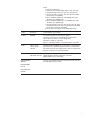
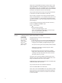
The following table provides detailed instructions to clear storage on various Agilent instruments.
Product Number Storage
32220A, N6700A USB port
548XX, 16900,
167X, 168X
How to Clear Storage
The Agilent function generator (33220A) and new modular power supply
(N6700A) both have a USB 2.0 port as standard, but only support device
side USB. The only way to extract data from the USB port would be to
use an external PC and use a PC application. In addition, the USB
connector on these products does not use the standard computer side
USB connector and current available memory sticks will not plug in to
either of these products.
Infiniium scopes (548XX) and all logic analyzers (16900, 167X, 168X)
have USB ports and additionally are PC-based instruments and run
MS Windows ®. They have fully functioning PCs inside with hard-drives
and memory. The products use one of two PC boards, either a VP22
(Infiniium and the six-slot 16900 models) and the three-slot 16900,
167X and 168X use an SC815. (Infiniium is moving to the SC815
in September 2004).
The USB ports can be disabled as follows:
VP22:
1. Power on the instrument.
2. During the black and white Agilent splash screen, press the
[DEL] key.
3. Using the cursor keys, select “Integrated Peripherals” and press
[ENTER].
4. Highlight “USB Controller”. Press [ENTER], then select “Disabled”,
press [ENTER] again.
5. Press [ESC] to return to the Main Menu.
6. Select “Set Supervisor Password” to set the BIOS password. Press
[ENTER]. Enter new password. Press [ENTER]. Confirm new
password. Press [ENTER].
7. Press [F10] to save settings and exit “CMOS Setup Utility”.
2
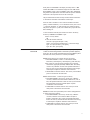
SC815:
1. Power on the instrument.
2. During the black and white Agilent splash screen, press [F2].
3. Using the left/right cursor keys, select the “Advanced” tab.
4. Using the up/down cursor keys, select the “Advanced Chipset
Control” listing. Press [ENTER].
5. Select “Embedded USB Device”. Press [ENTER], then select
“Disabled”, press [ENTER] again.
6. Select “Embedded USB Device 2”. Press [ENTER], then select
“Disabled”, press [ENTER] again.
7. Using the left/right cursor keys, select the “Security” tab. Select
“Set Supervisor Password”. Enter new password. Press [ENTER].
Confirm new password. Press [ENTER].
8. Press [F10] to save settings and exit “BIOS Setup Utility”.
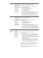
11713A
No memory
To clear registers, recycle power.
11713B/C
EEPROM
4 save recall state will not clear by factory default.
You need to manually clear it. Immediately after factory default,
(do not switch any channel or set any voltage) press:
Save/Recall > STATE 0 > Save State.
STATE 1 > Save State. STATE 2 > Save State. STATE 3 - Save State.
33220A
256 k waveform
memory, 5 state
memories
SYSTEM: SECURITY: IMMEDIATE command destroys all user-defined
state information, user-defined arbitrary waveforms, and user-defined
I/O settings. Power off clears volatile memory. There is a USB port but
there isn’t a memory stick or internal hard disks.
3458A
20 K “V” and 128 K
with an OPT. 14 K “NV”
[DELSUB] deletes subprograms.
[SCRATCH] deletes all stored subprograms and states.
[PURGE] deletes only one stored state.
E4401B/02B/04B/
05B/07B
See page 12 for detailed information on how to erase/clear user data
in an ESA/EMC spectrum analyzer.
E4403B/E4408B/
E4411B
E7401A/02A/03A/
04A/05A
J7211A/B/C
EEPROM
Utility > Factory default > Yes > OK
3
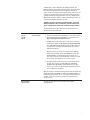
E4440A
The PSA Series spectrum analyzer offers a free security management
utilities software (Option HS7) and user guide. This can be ordered at
the time of purchase, ordered as an upgrade or downloaded from the
Web site at: www.agilent.com/find/ad
Click on Instrument Security and under spectrum analyzers click on
What procedure do I use to perform a security erase on a PSA Series
Spectrum Analyzer? The software offers three levels of security. Each
of the three security levels can be downloaded onto its own disk.
• Blank the display
• Erase user files
• Erase all memory including the operating system
There is a user guide and three security functions for PSA to download
from this site:
1. “HS7 Docs.pdf” contains the user instructions for the PSA Security
functions.
This document contains the recommended procedure for performing
a security erase on a PSA Series spectrum analyzer. Also included
in this document is the following:
• The size, type and usage information of the various volatile and
nonvolatile memories in the PSA Series spectrum analyzer.
• Recommended procedure for performing a security erase of the
various memory types.
• Important information on the security erase process.
NOTE: It is strongly recommended that these instructions are
read before using any of the PSA Security functions. Failure to
read and follow these instructions exactly may render your
PSA inoperable, and it will be necessary to send the PSA to an
Agilent Service Center to have it restored to operational condition.
2. “ScreenBlank.EXE” contains disk one, Screen Blanking
Functionality. This functionality is standard and does not need
to be downloaded if your PSA has firmware revision A.04.05 and
newer. Download this file to a freshly formatted 3.5” floppy disk
and execute it - it will extract the Screen Blanking files to be
installed in your PSA. Refer to the user instructions for detailed
installation instructions.
3. “EraseUserFiles.EXE” contains disk two, the “Erase User Files”
Routine. The user file erase routine will eliminate several user
files in the PSA memory. The instrument’s display will indicate
the removal of the respective files as they are being removed.
The memory consists of TRACE, STATE, LIMITS, SCREEN
CORRECTION AND LAST STATE information. The user erase
selectively erases all of the user information that is stored on
internal FLASH memory. Erase is defined as writing the single
character “1” over these memory locations. Download this file
to a freshly formatted 3.5” floppy disk and execute it - it will
extract the Erase User Files required to remove all user files
from your PSA. Refer to the user instructions for detailed
installation instructions.
4
“WIPESA.EXE” contains disk three, the “WIPESA” Routine. The
WIPESA routine erases the PSA’s operating system, which will render
the instrument inoperable. Disk three also performs the disk two
routine as well. It is strongly recommended to perform a backup of your
intrument as described in the user instructions. Download this file to
a freshly formatted 3.5” floppy disk and execute it - it will extract the
WIPESA files required to render your PSA inoperable. Refer to the user
instructions for detailed installation instructions.
CAUTION: This routine will render your PSA inoperable - if you fail to
follow the directions in the user instructions, your PSA will need to be
sent to an Agilent Service Center to be restored to operating condition.
The functionality and usage of disks one, two, and three are fully
described in the user instructions.
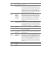
E4416A
E4417A
E4418B
E4419B
SRAM,
FLASH EEPROM
Power meters (EPM & EPM-P)
1. There are no floppy drives, USB interfaces on the power meters.
2. The instrument security documentation can be found on the
http://www.agilent.com/find/ad Web site.
3. The EPM Series power meters have a total memory capacity of
1.5 Mb. This comprises of 1 Mb SRAM and 0.5 Mb FLASH EEPROM.
The 1 Mb SRAM is further divided into two 0.5 Mb chunks, one
of which may be considered nonvolatile due to the on-board
lithium backup battery.
When the memory is cleared for security purposes, both the
volatile and nonvolatile chunks of the SRAM are erased. The
FLASH EEPROM is not erased during this procedure, as it is
only used to store the instrument firmware - it does not contain
any user data, and is therefore not a security concern.
4. The EPM-P Series power meters have a total memory capacity
of 3 Mb. This comprises of 2 Mb SRAM and 1 Mb FLASH
EEPROM. The 2 Mb SRAM is further divided into two 1 Mb
chunks, one of which may be considered nonvolatile due to the
on-board lithium backup battery.
When the memory is cleared for security purposes, both the volatile and
nonvolatile chunks of the SRAM are erased. The FLASH EEPROM is not
erased during this procedure, as it is only used to store the instrument
firmware - it does not contain any user data, and is therefore not a
security concern.
E4438C/E8247C/
E8257C/E8267C
See page 16 for security issues and solutions of the Agilent
signal generators.
5
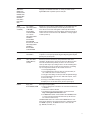
54621A
54641A
54810A/15A/
20A/25A/35A/
45A/45B/46A/
46B
1.44 MB floppy disk drive
2 M “V” RAM (display)
2 M per analog channel
“V” RAM (acquisition)
4 M total for all digital
channels “V” RAM
(acquisition)
12 K “NV” RAM
(scope setups)
96 K “NV” RAM
(waveform traces)
This procedure is applicable to Agilent/HP Infiniium oscilloscope
models 54621A, 54621D, 54622A, 54622D, 54624A.
1.44 MB floppy disk drive
2 M “V” RAM (display)
4 M per analog channel
“V” RAM (acquisition)
4 M total for all digital
channels “V” RAM
(acquisition)
16 K “NV” RAM
(scope setups)
128 K “NV” RAM
(waveform traces)
This procedure is applicable to Agilent Infiniium oscilloscope models
54641A, 54641D, 54642A, 54642D.
6 GB hard drive
120 MB floppy disk drive
64 MB RAM
(mother board)
32 K “ NV” RAM
(Intfc. Assy)
1 M “V” RAM
(Intfc. Assy)
1 M “V” RAM
(Disp. Assy)
This procedure is applicable to Agilent/HP Infiniium oscilloscope models
54810A, 54815A, 54820A, 54825A, 54835A, 54845A/B and 54846A/B.
The Agilent/HP Infiniium oscilloscope can be declassified by
performing the following eight steps:
1. Remove signals from front panel.
2. Press the [Save Recall] front panel key.
3. Press [Default setup] soft key.
4. Press the [Save] soft key.
5. Press the [To] soft key and select “INTERN_0”.
6. Press the [Press to Save] soft key. This stores the default set
and trace base line to trace memory and setup memory INTERN_0.
7. Repeat steps 5 and 6 for INTERN_1 and INTERN_2.
8. With no signal attached to the scope, press the [Autoscale] key
twice to ensure that the undo autoscale memory is cleared.
Infiniium oscilloscope can be declassified by performing the
following eight steps:
1. Remove signals from front panel.
2. Press the [Save Recall] front panel key.
3. Press [Default setup] soft key.
4. Press the [Save] soft key.
5. Press the [To] soft key and select “INTERN_0”.
6. Press the [Press to Save] soft key. This stores the default set and
trace base line to trace memory and setup memory INTERN_0.
7. Repeat steps 5 and 6 for INTERN_1 and INTERN_2, and INTERN_3.
8. With no signal attached to the scope, press the [Autoscale] key
twice to ensure that the undo autoscale memory is cleared.
The Agilent/HP Infiniium oscilloscope can be declassified by
performing three steps:
1. Cycle power on the scope. This clears all of the volatile RAM memory.
2. Switch to Default Setups two consecutive times (Push [Default
Setup] key, then immediately push [Default Setup] key again).
This process insures a generic setup in battery-backed nonvolatile
RAM on the scope interface assembly and generic setup in
nonvolatile hard disc drive.
3. Remove the hard disc drive from the instrument completely.
Replace with a separate hard disc drive (an Infiniium hard drive
containing no security issues). Refer to the service manual for
the part numbers for the hard disc drive for your scope.
The hard disc drive contains the Windows operating system, Scope
operating system, setups, waveform memories, waveform files, screen
images, and calibration data for the scope and probes.
All RAM information is duplicated on hard disc drive. This enables proper
startup and operation after a shut down.
6
This procedure declassifies all of the RAM as listed below:
There are 64 MB of RAM on the mother board.
There is also 32 K of nonvolatile RAM on the scope interface assembly,
which stores the last scope setting prior to power down. Switching to
default setups insures that a known and consistent set of information
is stored in this RAM.
Finally, there is volatile RAM on the display assembly. There is 1 MB
volatile video RAM for save waveform display data and 1 MB volatile
display RAM for screen colors. This RAM is used to aid in multiplexing
the graticule and alphanumeric information with the dynamic waveform
information of the acquisition section of the oscilloscope.
This procedure will insure that all setup and measurement information
is removed from all models of the Infiniium oscilloscopes.
54830B/D,
54831B/D,
54832B/D
54833A/D
20 GB hard drive
120 MB floppy disk drive
512 MB RAM
(mother board)
512 MB RAM
(mother board)
32 K “ NV” RAM
(Intfc. Assy)
1 MK “V” RAM
(Intfc. Assy)
1 MK “V” RAM
(Disp. Assy)
This procedure is applicable to Agilent Infiniium oscilloscope models
54830B/D, 54831B/D, 54832B/D and 54833A/D scopes.
The Agilent Infiniium oscilloscope can be declassified by performing
three steps:
1. Cycle power on the scope. This clears all of the volatile RAM memory.
2. Switch to Default Setups two consecutive times (Push [Default
Setup] key, then immediately push [Default Setup] key again).
This process insures a generic setup in battery-backed nonvolatile
RAM on the scope interface assembly and generic setup in
nonvolatile hard disc drive.
3. Remove the hard disc drive from the instrument completely.
Replace with a separate hard disc drive (an Infiniium hard drive
containing no security issues). Refer to the service manual for
part number of the hard disc drive part for your scope.
The hard disc drive contains the Windows operating system, Scope
operating system, setups, waveform memories, waveform files, screen
images, and calibration data for the scope and probes.
All RAM information is duplicated on hard disc drive. This enables proper
startup and operation after a shut down.
This procedure declassifies all of the RAM as listed below:
There are 512 MB of RAM on the mother board.
There is also 32 K of nonvolatile RAM on the scope interface assembly,
which stores the last scope setting prior to power down. Switching to
default setups insures that a known and consistent set of information
is stored in this RAM.
7
Finally, there is volatile RAM on the display assembly. There is 1 MB
volatile video RAM for save waveform display data and 1 MB volatile
display RAM for screen colors. This RAM is used to aid in multiplexing
the graticule and alphanumeric information with the dynamic waveform
information of the acquisition section of the oscilloscope.
This procedure will insure that all setup and measurement information
is removed from all models of the Infiniium oscilloscopes.
If the user loads a waveform to one of the four waveform memories
(Setup -> Waveform Memory -> Pick a waveform memory and a source
-> “Load from waveform” or “load from file”), this waveform memory
will persist after power is cycled, even if Default Setup is pressed twice
before shutting off.
To clear waveform memories (and all other user data in all memory
locations) in 5483XB/D and 5485XA scopes:
Control -> Factory default
OR
To clear the waveform memories:
Close the scope application (File -> Exit)
Open a command prompt window (Start -> Command Prompt)
Type “cd\scope\memories”, press [Enter]
Type “del *.wfm”, press [Enter]
54852A/53A/
54A/55A
20 GB hard drive
1.44 MB floppy disk drive
512 MB RAM
(mother board)
32 K “ NV” RAM
(Intfc. Assy)
1 MK “V” RAM
(Intfc. Assy)
1 MK “V” RAM
(Disp. Assy)
This procedure is applicable to Agilent Infiniium oscilloscope models
54852A, 54853A, 54854A, and 54855A.
The Agilent Infiniium oscilloscope can be declassified by
performing three steps:
1. Cycle power on the scope. This clears all of the volatile RAM memory.
2. Switch to Default Setups two consecutive times (Push [Default
Setup] key, then immediately push [Default Setup] key again).
This process insures a generic setup in battery-backed nonvolatile
RAM on the scope interface assembly and generic setup in
nonvolatile hard disc drive.
3. Remove the hard disc drive from the instrument completely.
Replace with a separate hard disc drive (an Infiniium hard drive
containing no security issues). Refer to the service manual for
the hard disc drive for your scope.
The hard disc drive contains the Windows operating system, Scope
operating system, setups, waveform memories, waveform files, screen
images, and calibration data for the scope and probes.
All RAM information is duplicated on hard disc drive. This enables proper
startup and operation after a shut down.
This procedure declassifies all of the RAM as listed below:
There are 512 MB of RAM on the mother board.
There is also 32 K of nonvolatile RAM on the scope interface assembly,
which stores the last scope setting prior to power down. Switching to
default setups insures that a known and consistent set of information
is stored in this RAM.
8
Finally there is volatile RAM on the display assembly. There is 1 MB
volatile video RAM for save waveform display data and 1 MB volatile
display RAM for screen colors. This RAM is used to aid in multiplexing
the graticule and alphanumeric information with the dynamic waveform
information of the acquisition section of the oscilloscope.
This procedure will insure that all setup and measurement information
is removed from all models of the Infiniium oscilloscopes.
If the user loads a waveform to one of the four waveform memories
(Setup -> Waveform Memory -> Pick a waveform memory and a source
-> “Load from waveform” or “load from file”), this waveform memory
will persist after power is cycled, even if default setup is pressed twice
before shutting off.
To clear waveform memories (and all other user data in all memory
locations) in 5483XB/D and 5485XA scopes:
Control -> Factory default
OR
To clear the waveform memories:
Close the scope application (File -> Exit)
Open a command prompt window (Start -> Command Prompt)
Type “cd\scope\memories”, press [Enter]
Type “del *.wfm”, press [Enter]
E5505A
Nonvolatile EEPROM
Volatile RAM
Nothing is stored in any of the N550xA instruments (with power off) that
could be construed as being related to measurement parameters (frequency,
power, etc.). All non-unique supported instruments in the E5505A systems
have their own memory and are not covered by the E5505A.
N5500A phase noise test set contains two types of memory:
1. Nonvolatile EEPROM - Contains no measurement-related
information (carrier frequency, offset frequency, power level, etc.).
It does contain its own instrument type/option info, instrument
serial number, signal path (and other) calibration data. This memory
contains only calibration constants and operational firmware. It
does not store any measurement data whatsoever and erasing it
would require complete re-calibration of the instrument.
2. Volatile RAM - Instrument state info. This memory is erased when
power is removed from the instrument.
N550xA downconverters - contain two types of memory:
1. Nonvolatile EEPROM - this memory contains only calibration
constants, calibration instrument interface address info, YTF cal
data, and operational firmware. It does not store any measurement
data whatsoever and erasing it would require complete
re-calibration of the instrument.
2. Volatile RAM - Instrument state info. This memory is erased
when power is removed from the instrument.
N5508A microwave source (stand-alone) is also used in A/D applications.
It contains two types of memory:
1. Nonvolatile EEPROM - this memory contains only calibration
constants, reference source interface address info (but no
frequency information), YTF cal data and operational firmware.
It does not store any measurement data whatsoever and erasing
it would require complete re-calibration of the instrument.
2. Volatile RAM - Instrument state info. This memory is erased
when power is removed from the instrument.
9
10
6624A
128 K “NV” EPROM
Recycle power.
6654A
2 K EEPROM / 64K RAM The 664x, 665x, 667x, 668x & 6610x family of supplies have the same
512 K ROM / 0 NVRAM interface. There are five (5) nonvolatile store/ recall states you may
save output voltage and current settings along with protection features.
To remove the stored stated you must do a *RST to each state saved or
purposefully store “0” in each location from the front panel. These
supplies will always come up at turn on to the state stored in state zero.
The calibration of voltage and current occupy 256 K of ROM and are
password secured during calibration. The remainder of ROM is power
supply firmware and is not customer accessible.
N6700A
Mainframe:
1 KB EEPROM
8 MB Flash
32 MB RAM
Each module:
2 KB EEPROM
8114A
6 128 K by 8 bit EPROM The EPROM’s contain no customer data. The RAM has nine locations
2 128 K by 8 bit RAM
for customer data. To purge customer data, overwrite all nine locations
with the standard settings as follows: Load the standard settings, press
[SHIFT] [RECALL] [0]. Then store the settings in the other nine registers.
Press [STORE] [1]. Press [STORE] [2]. . . . . . . Press [STORE] [9].
83020A
No memory
E836x
Removable hard drive
83630B
S/N < 3104A
500 K UVEPROM / 32 K Blanking display press [MENU] [MORE] [SECURITY MENU] [BLANK
This EEPROM / 260 K DISPLAY] turns off the four lines of display and deactivation is only by
“NV” RAM
presetting synthesizer.
83630B
S/N ³ 3104A
1M UVEPROM / 64 K
EEPROM / 780 K
“NV” RAM
Blanking frequency display press [MENU] [MORE] [SECURITY MORE]
[ZERO FREQ]. Zeros are displayed in freq. And deactivation is only by
presetting synth. Clearing memory press [MENU] [MORE] [SECURITY
MENU] [CLEAR MEMORY]. When [CLEAR MEMORY] is selected, synth.
Displays “# OF TIMES TO CLEAR MEMORY: X”. Enter the number of
times the state info. Should be overwritten with all 1’s and 0’s. This
writes 1’s and 0’s over all instrument states, save/recall registers, and
frequency lists a selectable # of times and return the synth. To factory
preset state.
84813A
No memory
-
84904K
No memory
-
84907K
No memory
-
The N6700A is a mainframe that can have up to four power supply
modules installed. Flash memory contains only instrument firmware.
RAM is volatile. Mainframe and module EEPROM contain internal system
parameters plus some customer data such as I/O configuration, user
preferences and saved instrument states. All customer data can be
reset from the front panel by using the menu. Select the \System\
Preferences\Security\ResetNvRam dialog box and then press the
[Reset] button.
Please see page 20 for detailed information on how to maintain the
PNA in a secured environment.
8560 Series:
8560A/61A/
62A/63A/61B/
62B/60E/61E/
62E/63E/64E/
65E/60EC/
61EC/62EC/
63EC/64EC/
65EC
See page 23 for detailed information on security procedures for the
Agilent 8560 Series of portable spectrum analyzers.
8563E
s/n <=3305A
(same procedure 128 K Display RAM
as 8563EC)
1.2 M RAM /
16 K EEPROM
12 M UVEPROM
s/n >=3310A
128 K Display RAM
4 M RAM /
16 K EEPROM
8 M UVEPROM
Firmware Rev >931216
128 K Display RAM
4 M RAM /
64 K EEPROM
12 M UVEPROM
If there isn’t a mass memory module present, or if the module does not
contain DLP’s, preset the analyzer and save the preset states and
traces into each trace and state register to declassify the instrument.
Another method would be to remove the battery and leave power off for
at least one hour. Ensure that Error 718 “BATTERY ?” message appears
on CRT at power up.
8722ES
512 K NVROM
2 M V RAM +
See Chapter 12 in User’s Guide. The 2M RAM can be increased depending
on options. To clear press [Save/Recall] [Clear Register] [Clear All] then
[Preset] and cycle the power.
81101A
128 K “NV” RAM
PCMCIA Memory
Card Slot
All memory locations that hold any setup information needs to be
overwritten. The 81101A has 10 memory locations, 0-9. Memory location
zero holds the default setup. Memory locations 1-9 can be used to
store any other setups. By recalling locations 1-9 and overwriting them
with information in memory location zero, the generator is not holding
any user setup but the default one. All customer has to do is:
1. Press the [Shift] blue key.
2. Press the [Recall] key (same key that says store but when you
are in shift mode, this is now the recall key).
3. Press [0] to recall settings in memory location zero (default settings).
4. Press the [Store] key (you are not in shift mode anymore, so this
is now the store key).
5. Press [1] to store default settings in memory location one.
6. Repeat process for all other memory locations (2 through 9).
N897xA
Floppy drive
Noise figure analyzers (NFA)
Flash EEPROM, DRAM
1. There is a floppy drive on the NFA - this cannot be removed easily
or disabled.
2. There is not a USB on the NFA.
3. The instrument security documentation can be found on the
http://www.agilent.com/find/ad Web site.
4. The N897xA NFA Series contains 8 MB of Flash EEPROM, which
is used to store the instrument firmware and any files the user
has saved to internal memory.
The N897xA NFA Series also contains 16 M of DRAM which is used
during normal operation. The instrument firmware is loaded from Flash
into DRAM on power up. The DRAM also stores current user files
(e.g. ENR files, limit lines, etc.).
11
How To Erase/Clear User Data
In an ESA/EMC Spectrum Analyzer for Security Reasons
Warnings
FLASH
Be sure that all information stored by the user
in the instrument that needs to be saved is
properly backed-up before attempting to clear
any of the instrument memory. Agilent cannot
be held responsible for any lost files or data
resulting from the clearing of memory.
This is where the instrument stores:
In most cases there will be no user prompts
to confirm the clearing or deleting of files or
instrument memory. Be sure to read this document entirely before proceeding with any file
deletion or memory clearing.
• Option license keys (ESA analyzers only)
• Instrument firmware/operating system
• Installed measurement personalities
(ESA analyzers only)
• Loaded user limit lines
• Loaded user amplitude correction factors
• User preset data
Types of internal memory that can
store user information
DRAM
This memory is volatile so any information
stored by the instrument in this area is lost
when the instrument is turned off. This is the
memory that the instrument uses to run its
processes out of.
SRAM
• Instrument states and setups
• Trace data
• Limit line files
• Screen images
This memory stores such system information as:
• Amplitude correction files
• Self alignment data
• Reports (EMC analyzers only)
• Current time & date
• Signal lists (EMC analyzers only)
• Remote interface configuration
This memory is nonvolatile, so nothing is lost
when the instrument power is removed.
• Printer setup information
• Last state settings
• Segmented sweep settings
(ESA-E analyzers only)
• Misc. instrument system information
This memory is battery backed-up, so it is not lost
when the power is removed from the instrument.
12
The user C: drive is also stored in this memory,
which could contain the following file types
that the user can save internally:
Clearing the different types of memory
DRAM
This memory is volatile. All you have to do is
remove the power to the instrument and all data
stored in it will be lost.
after is has been cleared. This would include
such things as:
• Instrument firmware disk set 2
SRAM
This is volatile memory that is kept alive with
an internal battery, and the battery cannot be
removed to clear the memory without taking the
instrument apart. However, there is a procedure
that can be used to have the instrument clear
most of this memory itself.
To clear the SRAM memory, follow this procedure:
• Turn the instrument Off.
• Turn the instrument back On while holding
down both the [ESC] & [Return] front panel
keys 1.
• Continue hold these two keys for 10 second
after pressing the [On] button.
• The instrument will now clear it’s SRAM
memory and then power up.
Information such as the current time and date
will not be erased by this procedure.
FLASH
This type of memory will hold its information
indefinitely without any backup supply. It will
have to be erased electronically. There is a procedure that can be used to make the instrument
completely clear this memory itself.
Since the FLASH memory does contain all of the
files required to operate the instrument, you will
want to be sure that you have what is needed to
restore it to an operating condition
1.
2.
3.
• Measurement personality disk sets
(ESA analyzers only)
• Installed option license keys 3
If there are any user saved files on the C: drive
that need to be saved, they can be copied to a
floppy disk inserted into the A: drive, then
re-stored at a later time.
To clear the FLASH memory, follow this
procedure:
• Turn the instrument Off.
• Turn the instrument back On while holding
down both the [ESC] & [View/Trace] front
panel keys 1.
• Continue to hold these two keys for 10 seconds
after pressing the [On] button.
• The instrument will now clear it’s flash
memory.
• Allow 10 minutes for this process to
complete, as there will be no visual indication
of when it is done.
• Unplug the instrument to turn it off, as the
Standby button will not work at this point.
Since this memory contains the instrument
firmware/operating system, the instrument will
be non-functional at this point. You will need to
refer to the section below to determine what is
needed to return it to an operating condition.
Both SRAM and FLASH can be cleared at the same time if all three of
the [ESC], [Return], & [View/Trace] front panel keys are held down during this process.
If a disk set of the latest version of instrument firmware is needed, go to:
http://www.agilent.com/find/esa_firmware for ESA analyzers
http://www.agilent.com/find/emc_firmware for EMC analyzers
To retrieve license key information from an instrument the following remote query
needs to be used: :SYST:LKEY? ‘option number’
For example, to retrieve the license key for the ESA phase noise measurement utility
(Option 226) use: :SYST:LKEY? ‘226’
This will need to be done for each licensed option that is installed. To obtain a list of the
installed licensed options in an instrument Press: [System] [More 1 of 2] [More 2 of 3]
[Personalities]. License keys will need to be saved for all licensed options listed.
13
Recovering from clearing
the instrument memory
DRAM
FLASH
No recovery required. The information in this
memory is built by the instrument
every time it is turned on.
At this point the instrument will not function, as
there is no operating system installed.
SRAM
Once the SRAM is cleared and the instrument
has finished powering up, cycle the power once
again to load all installed measurements.
The “System, Alignments, Align Now, All
Required” message will be displayed on the
screen. You will need to manually perform a
front panel alignment of the instrument before
using it. Follow the key press sequence in the
on-screen message to do this, being sure to
connect the AMPTD REF OUT to the RF INPUT
if the instrument is equipped with one. Refer
to your instrument’s Getting Started Guide if
further instructions are required on how this is
done. If the instrument has a remote interface,
and it was configured to anything other than the
default settings, it will need to be re-configured.
This would include the settings for both the
remote control interface as well as the parallel
printer port.
14
To install the instrument firmware/operating
system and return the instrument to
an operating condition do the following:
• Insert the firmware loader disk into the floppy
drive and turn the instrument power on.
• Follow the on-screen prompts to install the
firmware and measurement suite.
• When the installation is complete Press:
[System] [More 1 of 3] [Restore Sys Defaults]
[Restore Sys Defaults].
The “System, Alignments, Align Now, All
Required” message will be displayed on the
screen. You will need to manually perform a
front panel alignment of the instrument before
using it. Follow the key press sequence in the
on-screen message to do this, being sure to
connect the AMPTD REF OUT to the RF INPUT
if the instrument is equipped with one. Refer
to your instrument’s Getting Started Guide if
further instructions are required on how this
is done. If optional measurement personalities
were installed (ESA analyzers only) you will
now need to re-install them and their license
keys. Refer to the User’s Guide for these measurement personalities for detailed instructions
on how this is done. Before re-installing any
measurement personalities it would be best to
verify that the latest versions are being used.
To find a listing of all the latest versions go to:
http://www.agilent.com/find/esa_revisions
Deleting user information without
clearing memory
This is a list of all of the different places that
user information could be saved, as well as
information on how to delete it without totally
erasing the instrument memory. Of course, this
may not be as secure of an erase as clearing the
memory would be, but it will help to find all of
the information that could contain classified
information. The following are locations where
user information can be stored:
• LIM
limit line
• GIF
screen image
• BMP
screen image
• ANT
antenna corrections
• CBL
cable corrections
• Saved user files on the C: drive
• OTH
other corrections
• Loaded Amplitude correction data
• AMP
user corrections
• Loaded Limit Line data
• LIS
signal list (EMC analyzer only)
• User Preset
• HTM
report (EMC analyzer only)
• Last state settings
• Trace registers
• Segmented Sweep settings
(ESA-E analyzer only)
• Signal List (EMC analyzer only)
Clearing the individual types of user
information:
Saved user files on the C: drive
Loaded Amplitude correction data
Press: [Amplitude] [More 1 of 3]
[Corrections] [More 1 of 2] [Delete All
Corrections}] [Delete All Corrections]
Loaded Limit Line data
Press: [Display] [Limits] [Delete All Limits]
[Delete All Limits]
User Preset
Press: [Preset] [Factory Preset (if displayed)]
[System] [Power On/Preset] [Save User Preset]
Press: [File] [Delete] then select and
delete all files of the following types:
Last State Settings
Press: [Preset] [Preset]
• SET
instrument setup
Trace registers
A power cycle will clear all three trace registers
• STA
instrument state
• TRC
trace & state
• CSV
trace & state
Segmented Sweep settings (ESA-E analyzer only)
Press: [Sweep] [Segmented] [Modify] [Delete]
[Delete]
Signal List (EMC snalyzer only)
Press: [Measure] {More 1 of 2} [Signal List]
[Delete Signals] [Delete All] [Yes]
15
Security of Agilent Signal Generators Issues and Solutions
Instrument security
To protect sensitive data, it is important for signal
generator users to understand the generator’s
features. There are three main areas which must
be considered when determining appropriate
security measures in relation to the generator ’s
use.
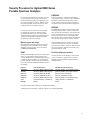
Storage media
Storage media, or memory for user information,
can be categorized into two groups: explicit
Memory
description
16
and implicit. Explicitly stored information consists of data enter by the user. Implicitly stored
information includes items such as IQ calibration data, user flatness, table editor files, and
last state information. This information is stored
in various memory devices within the signal
generator. Understanding the memory devices
used within the signal generator enables users to
define best-practice security measures for their
application needs.
Contents
Location
Persistence
DRAM
Running firmware code temporary
operational storage
Processor board,
baseband
Memory contents are
completely erased when
powered off for longer than a
few seconds.
SRAM
Certain user-editable data (table editors),
last state and last state back-up,
state storage
Generator board
Memory contents do not get
erased by turning off the
power because the memory is
connected to a back-up battery.
(The battery is located on the
processor board in the
E82x7C, or on the mother
board in the E4438C).
CPU flash
User files including: flatness
calibration, IQ calibration, instrument
states, waveforms, modulation definitions,
sweep lists, firmware code and
factory calibrations
Processor board
Memory contents cannot be
removed by turning off power.
A low-level erase procedure
will completely clean the
contents in a single cycle.
Note: since this memory
contains both factory data and
user data, a full chip erase is
not desirable. However, user
data areas can be selectively
and completely sanitized.
Other flash
Factory calibration and information
files, code images, and self test limits
RF boards, baseband
generator board,
motherboard
Memory remains intact
through power cycles, however,
there is no security concern
because there is no user
information in this memory.
Hard disk
User files including:
flatness calibrations, IQ calibration,
instrument states, waveforms,
modulation definitions, and sweep lists.
Note: the hard disk is an option and
is therefore not present in some
instruments. If it is present, the listed
files are stored on the hard disk
instead of in flash memory.
Instrument chassis
(controlled by
processor board)
Memory contents cannot be
removed by turning off power.
The magnetic residue will
require several rewrite
cycles or drive removal
and destruction.
Display
The second element to consider in generator
security is the display, as it can reveal sensitive
information. To prevent unauthorized people
from reading the instrument display, it can be
blanked. In this mode, no information appears
on the display. Once the display is blanked,
one must cycle the power on the instrument to
re-enable the display. In the reboot sequence,
the Erase All action (described later in this
document), is performed to remove all user
information so that the stored states cannot
be retrieved.
I/O ports
The I/O ports must also be considered, since
they allow remote access to the instrument.
These ports, which provide access to all user
settings, user states, and display images, include
the GPIB, LAN, and RS-232. To prevent remote
access to these ports, the physical area around
these connections must be tightly controlled.
There is also a “ping” service, which presently
cannot be selectively disabled. The concern
here might be that it is possible to discover IP
addresses of connected instruments in order to
query their setups over the Internet, or break
into the code.
Application environments
To illustrate how to safeguard the content on
signal generators, four use scenarios are provided.
1. The instrument is moved between users
or shared by many users
In this instance, security measures may
necessitate that all user files and information
be cleared to prohibit other users from
accessing this information through the
instrument interface. In this scenario, we
assume that other people will not take the
instrument apart and analyze the internal
chips or storage media. For this scenario,
use the Erase All feature described in
Using Security Commands.
2. The instrument is used in a secure area
In this circumstance, people walking past
should not be able to access the instrument
or read any information from the display.
Remote access through the I/O ports is
limited or controlled. For this scenario, the
front panel must be used to blank the display
and access to the I/O ports must be controlled.
(Refer to Using Security Commands.)
3. The instrument is moved from a
secure area to an insecure area
When the signal generator is relocated from
a secure area to an insecure area, all user
information must be removed. The information
should not be recoverable even if someone
takes the instrument apart and analyzes
the storage media. For this scenario, use
the Erase and Sanitize All feature described
in Using Security Commands.
4. The instrument fails in a secure area and
must leave the secure area to be repaired
This case means that the instrument is not
functioning and cannot clear its own storage
media. None of the storage media can leave
the secure area. The instrument without
storage media can leave the secure area
to be repaired. For this scenario, use the
procedures noted in Hardware Removal.
17
Using security commands
The built-in security features of Agilent signal
generators are accessed by various methods,
depending upon the element of the generator to
be secured.
Memory
Memory security features are accessible by
soft key menus on the front panel and by SCPI
commands through the remote interface.
Key entry
Options for erasing memory are obtained
through a series of keystrokes.
Utility
Utility
Utility
[Memory Catalog] [More] [Erase All]
[Confirm Delete]
[Memory Catalog] [More] [Erase and
Overwrite All] [Confirm Delete]
[Memory Catalog] [More] [Erase and
Sanitize All] [Confirm Delete]
SCPI commands
To erase memory from a remote location, SCPI
commands can be sent to the signal generator.
SYStem:SECUrity:ERASeall
SYStem:SECUrity:OVERwrite
SYStem:SECUrity:SANitize
These three commands perform as described
below.
Erase All
This procedure removes all user files and user
information so they are not accessible through
the instrument interface. This action will
remove only the file references and clear all
table editors without sanitizing the memory.
The instrument will appear in a similar state
as it was shipped from the factory. The action
will include all user files, table editor contents,
user flatness calibration, and user IQ calibration. This action will be relatively quick, taking
less than one minute. (Note: this is different
than the current Delete All Files key under the
Utility >Memory Catalog >More menu which
deletes all user explicit files but not current
table editor files.)
18
Erase and Overwrite All
The command includes the Erase All procedure
from above. It then clears the memory according
to the security standards defined by the United
States’ Department of Defense (DOD).
All addressable locations are overwritten with
random characters in the SRAM, DRAM and
hard disk. All addressable locations in the CPU
flash also are overwritten with random characters, and then the flash blocks are erased. This
is equivalent to erasing entire chip but is only
done on the areas of the chip, which are no longer in use.
Erase and Sanitize All
The procedure undertakes the measures
included in Erase and Overwrite All from above.
In clearing the SRAM, the user is required
to wait at least the same amount of time the
instrument was used in the secure area to
comply with SRAM sanitation. Each overwrite
must reside in memory for a longer period than
the classified resided in memory. (Alternatively,
the SRAM battery could be removed and
reinserted manually. See issues below.)
On the hard disk, all addressable locations are
overwritten with a single character, its complement, then a random character, and then
verified. (Note: this is insufficient for top secret
data according to the DOD standard. For top
secret data, the hard drive must be removed
and destroyed.)
DRAM memory is overwritten with a single
character; then the instrument must be
powered off.
Display
Other security factors
Blocking the display of sensitive data can be
done using the generator’s entry keys or using
SCPI commands.
Given that firmware commands are an inherent
part of the virtually all electronic equipment,
there are some security measures which may be
impractical to implement. These relate to the
following areas:
Key entry
[Utility] [Display] [More] [Display Off]
[Confirm Display Off]
SCPI command
:DISPlay [:WINDow ] [:STATe ] ON|OFF|1|0
I/O Ports
While controlling access to the generator’s ports
is the leading security measure, the LAN port
provides four services, which can be selectively
disabled:
• http
• ftp
• sockets
• telnet
There is also a “ping ” service, which presently
cannot be selectively disabled. It should be
noted that this service makes it is possible to
discover IP addresses of connected instruments
in order to query their setups over the Internet,
or break into the code.
Hardware removal
In the following circumstances, security
measures may make it necessary to disassemble the instrument.
• If the instrument is non-functioning,
the internal security features cannot be
accessed. The storage media must be
removed so the instrument can be sent to a
repair facility.
• If top-secret data has been stored, the
storage media must be destroyed.
SRAM
According to DOD sanitize standards, a back-up
battery should be removed. This requires opening
the instrument (and thus voiding the warranty).
The alternative is to perform a DOD clear and
then wait for a period longer then the instrument
was in use. Solutions include adding a software
controlled “battery switch ”, adding an externally
removable battery tray, or describing how to disassemble and remove the battery.
FLASH
Since the factory calibration files are stored
along with the user files, a “chip erase ” cannot
be performed. However, selective block erase
achieves the same purpose.
DRAM
This area of memory is ignored in security
features since its content is lost (erased) after
powering down the instrument.
Conclusion
Aglient ’s signal generators combine outstanding
RF and microwave performance and baseband
generation to deliver calibrated test signals at
baseband, IF, and RF microwave frequencies.
While the nature of the equipment requires the
storage and use of data, generator features and
operating practices can be combined to effectively safeguard data during the generator’s use.
To ensure data protection in security-sensitive
applications, the information is easily erased to
DOD-standards using built-in utilities.
In these circumstances, the hard disk and the
processor board must be removed. The assemblies can be reinstalled after the instrument has
been repaired, or they can be destroyed.
19
Maintaining the PNA in a secured environment
Maintaining security
In many cases it is imperative that the PNA be
used in a secured environment. Generally these
secured environments will not allow any test
equipment to leave the area unless it can be
proven that all devices capable of maintaining
memory have been thoroughly erased. This, in
conjunction with the Windows operating system,
presents some difficulties when the PNA must
be transported to a non-secure environment
such as a repair/calibration facility.
Please note that some of this information is
dependent upon the CPU board used in your
PNA. For purposes of this document, these are
divided into “older CPU” and “newer CPU.” You
can easily determine which of these you have
by looking at the rear panel USB port on the
CPU board. If it is horizontal, it is an older CPU
board, otherwise it is a newer board. All PNAs
shipped since about March 2002 have the newer
CPU board.
Battery information
There are no batteries in the PNA other than the
one used to power the clock chip on the CPU
board.
Types of memory
The PNA has several types of memory.
• The PNA has 64-512 MB of SDRAM in one
or two SODIMMs, but this is volatile memory
and it loses its memory as soon as power is
removed. This is not a security concern.
• The main nonvolatile device is, of course,
the hard drive. As of this writing it is a 10 GB
“laptop” hard drive. This is a security concern.
• Newer CPU boards have a compact flash
header, which could contain nonvolatile
compact flash memory, however, none is
installed at the time of shipment. This was
for possible future uses, but has not been
implemented. The presence of any compact
flash card is not dealt with in this document.
• Each board assembly may have one, two, or
three serial EEPROM devices. These devices
hold only 512 bytes each and are not generally
user accessible. These contain information
related to the installed hardware, such as
board serial number, options, correction
constants, offsets, DAC values, etc. This
data is required to make the PNA functional.
This data can be changed only by factory
personnel or by calibration labs when
performing adjustments. No user data is
stored in these locations.
20
Because it is virtually impossible to completely
and selectively erase all user data on a hard drive
without also destroying the operating system,
the best method for maintaining security when
the PNA must be removed from a secure area
is to replace the hard drive with a “non-secure”
hard drive (i.e. a drive that has never had any
sensitive data placed on it). This allows the PNA
to still function properly in non-secured areas
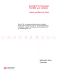
or for use when servicing. All microwave PNAs
(stop freq >= 10 GHz) have an easily accessible
hard drive on the rear panel. RF PNA’s have a
kit available that can also add easy rear-panel
accessibility (view picture). See below. This document does not detail the step-by-step instructions of how to remove the hard drive (see service manual for this). Instead, it documents the
general steps needed to maintain security. This
document assumes that this spare hard drive is
on hand.
Agilent has available a relatively inexpensive,
pre-configured hard drive for the PNA which
must be purchased in order for this security
method to work. Because there are two different
CPU boards and different mounting methods,
the proper part number must be ordered.
See below.
• For any microwave PNA (Stop Freq >10 GHz.)
All have the new CPU. Order model #
Z5623AHD2. This can be ordered at any time,
and can be specified with the purchase of
the PNA. It comes with a mounting tray and
complete operating system. It does not include
mxcal files for your specific instrument
(see below).
• For RF PNAs (Stop Freq <10 GHz) with new
CPU board. Order E8801-60063. This is just
a hard drive with the operating system on it.
Does not include mxcal files for your specific
instrument (see below).
• For RF PNAs with older CPU board. Order
E8356-60076. This is just a hard drive with
the operating system on it. Does not include
mxcal files for your specific instrument
(see below).
• For any RF PNA. To add the rear panel,
easy-access kit, contact Agilent. The part
number for this kit is E8356-60120, but it is
not orderable directly. This is just a mounting
kit and does not include the extra hard drive.
As shipped from the factory, all PNAs have very
little unique information stored on the hard
drive. This allows one hard drive to function on
most any PNA assuming it has the appropriate
type of CPU. However, there are a few small
instrument-specific files that contain some factory correction data. For best performance,
these should be copied to whichever hard drive
is being used. These files are not critical and, in
fact, are not even needed if a full user calibration is performed before measurement data is
taken. These files all begin with mxcalfiles and
are located in the directory: C:\Program Files\
Agilent\Network Analyzer. There may be several
of these files, all of them about 10 kB in size.
Whenever a new PNA is received, these files
should be backed up to a floppy disk. Don’t forget to label the disk with the model/serial number. This will save you the trouble of performing
service adjustment routines, should the hard
drive ever fail in the future.
The PNA can now be used elsewhere or sent
for servicing without fear of leaking any sensitive information. When the PNA needs to be
returned to the secured area, follow the below
steps. Any servicing of the PNA may include
the regeneration of correction constants. Most of
these are contained in the on-board EEPROMs
so no action is necessary. The only exception is
with the mxcalfiles (see below).
Step-by-step security
3. If the mxcalfiles have changed, copy all new
files saved to the floppy disk to the directory
listed above.
These steps should be followed to maintain
security:
1. Whenever a new PNA is received, or if this
step has not yet been done, copy any files
that begin with mxcalfiles to a floppy disk.
This disk should be maintained in a
non-secure area.
1. If the PNA was sent out for servicing, you
should first check to see if any of the
mxcalfiles have been updated (check the
last-modified date.) If so, these updated
files should be copied to a floppy disk so
that they can be updated on the secured
hard drive.
2. Remove the unsecured hard drive, transport
the PNA to the secured area, and replace
the hard drive with the secured version
4. Also, if the PNA was sent out for servicing,
it might have had its firmware updated
(see below for more information about this).
2. Purchase the appropriate spare hard drive
and keep it with the above floppy disk.
Clearly mark this hard drive as “unsecured”.
In the event the secure PNA needs to be
used elsewhere, or, if it needs servicing:
• Remove the secure hard drive (label it as
secured if desired) and keep it in the
secured area.
• Remove the PNA from the secured area
and install the “unsecured” hard drive.
• If not previously done, copy the mxcalfiles
from the floppy disk to the directory
listed above.
21
Additional notes
Other issues
Firmware that has been updated on the unsecured
hard drive during servicing can usually be copied to a memory media and used to update the
secured hard drive. The recommended method
is to use 64 MB (or more) USB key drives (a.k.a.
pen drives) to copy the firmware upgrade file
(a USB CD-RW could also be used but is much
more difficult.) This firmware installation file
usually resides on the D:\Upgrades\Firmware
directory. If not, the latest version can always
be obtained via the Internet.
It has been suggested that the USB may pose a
security risk, mainly due to the proliferation of
USB pen drives that are very small and can store
up to 2 GB of data. There are ways to prevent
the operation of these devices without affecting
the USB mouse or keyboard. Contact Agilent for
more information, or download this USB security word document for details.
Any account names and passwords that have
been created on either hard drive will not be
available on the other drive unless they are
manually installed; generally, this is a security
advantage.
The use of another hard drive will generate a
new Network ID (computer name) for the PNA
upon initial boot up. If this is not desired, the
Network ID should be changed immediately after
boot-up. See your system’s administrator for
complete information.
As shipped, the PNA has a back-up administrator account that is designed to be used by
Agilent service personnel. This also comes in
handy when a user forgets their password. The
password for this account is unique to each
instrument and is encrypted based upon the
serial number. This security is sufficient for
non-critical usage, but any high security location will probably want to delete this account.
However, if the administrator password is then
forgotten, the entire hard drive will have to be
replaced in order to make the unit functional
again.
For more information, go to:
http://na.tm.agilent.com/pna/security.html
You can access the Web site via the Help menu
on the PNA. There is also information on how to
remove frequency information from the screen
and printouts under Help.
Includes program that makes USB mass storage
devices unable to store data from the USB port
on the PNA. The program is on the Maintaining
the PNA in a Secured Environment Web page.
22
Security Procedure for Agilent 8560-Series
Portable Spectrum Analyzers
UVEPROM:
Be sure that all information stored by the user
in the instrument that needs to be saved is
properly backed-up before attempting to clear
any of the instrument memory. Agilent cannot
be held responsible for any lost files or data
resulting from the clearing of memory.
Processor firmware, which determines instrument functionality, resides in the UVEPROM.
Firmware is programmed onto chips which
are in sockets and can be readily changed to
incorporate later enhancements and bug fixes.
EEPROM:
In most cases there will be no user prompts
to confirm the clearing or deleting of files
or instrument memory. Be sure to read this
document entirely before proceeding with any
A-Series B-Series E-Series EC-Series 8560A
file deletion or memory clearing.
Memory types and usage
The EEPROM contains the instrument’s serial
ID string, model number, flatness calibration
data, preselector tuning data, microcircuit bias
values, external mixer conversion loss factors,
focus and intensity values, and elapsed time
data. See the table at the end of this document for
more details on instrument memory capacity.
The 8560-Series portable spectrum analyzers
contain processor assemblies which employ
different types of memory. These are RAM,
UVEPROM and EEPROM.
Downloadable Programs (DLPs) can be used
with these instruments only with an 85620A
mass memory module, which has built-in RAM
for these programs. DLPs do not reside in the
spectrum analyzer itself.
RAM:
Disabling display parameters
Battery-backed RAM is used to store instrument
states, user preselector peaks and for trace
storage. RAM which is not backed up by battery
is used for the instrument’s scratch pad. This
portion of RAM is erased when the instrument
power is turned off. Additional RAM is used for
the display.
Function
Annotation
Graticule
Disp Line
Threshold
Frequency
Trace
Soft keys
Various portions of the display can be turned
off by a simple key sequence. The sequence
depends on the instrument model number as
described below.
61A, 62A/B Sequence
[DISPLAY] {MORE} {ANNOT ON OFF}
[DISPLAY] {MORE} {GRAT ON OFF}
[DISPLAY] {DISPL LIN ON OFF}
[DISPLAY] {THRESHLD ON OFF}
[DISPLAY] {MORE} {FREQ DSP OFF}
[TRACE] {BLANK A} or {BLANK B}
[HOLD]
60A, 61B, 63A, 6XE/EC Sequence
[DISPLAY] {MORE 1 OF 2} {ANNOT ON OFF}
[DISPLAY] {MORE 1 OF 2} {GRAT ON OFF}
[DISPLAY] {DISPL LIN ON OFF}
[DISPLAY] {THRESHLD ON OFF}
[DISPLAY] {MORE 1 OF 2} {FREQ DSP OFF}
[TRACE] {BLANK A} or {BLANK B}
[HOLD]
Executing all of the above sequences can totally blank the display.
The blanking can be reversed by similar key sequences or by pressing [PRESET].
23
Frequency offset
A frequency offset for absolute frequency readouts such as center frequency can be entered.
To clear the “Last State” all that needs to be
done is to press [PRESET] twice.
For the 8561A and 8562A/B models press
[FREQUENCY] {MORE} {FREQ OFFSET} and
use the data entry keys.
The instrument’s Power On state is also saved
by pressing [SAVE] {PWR ON STATE}. This can
also be cleared by saving the preset state to it.
For the 8560A, 8561B, 8563A and 856XE/EC
models press [FREQUENCY] {FREQ OFFSET}
and use the data entry keys.
Removing the memory backup battery
The frequency offset is cleared by pressing
[PRESET] or by entering an offset of 0 Hz.
User memory: trace storage
Up to seven traces can be saved in trace storage
registers. If the traces are named, the name will
be stored as a soft key label for the register in
which the trace was stored. The trace register
and its corresponding soft key can be cleared
by pressing [PRESET] and storing the preset
state of the instrument in that register. Repeat
this process for all seven trace registers. Clear
trace storage memory by pressing [SAVE] {SAVE
TRACE A} or [SAVE TRACE B}, then the appropriate trace register.
User memory: instrument states
Up to ten instrument states can be stored in
instrument state registers. Instrument states
include frequency, amplitude, bandwidth and
other settings. As with trace storage, the states
can be named to label their soft key. These
registers can also be cleared by storing the
instrument preset state in them. State storage
is accessed by pressing [SAVE] {SAVE STATE},
then the appropriate State register.
Command
ANNOT
DL
FDSP
GRAT
PSTATE
HD
SAVET
BLANK
SAVES
24
User memory is retained in an internal lithium
battery (silver oxide in 8562A option H50 and
H51). User memory can be cleared by removing
the battery and leaving the line switch off for
over one hour. Remove the battery by removing the two screws on the battery cover on the
instrument’s rear panel. The battery can then be
removed from the battery holder. The battery
voltage to the RAM is controlled by a battery
manager circuit and stored in a capacitor on
the A2 controller board. Shorting the terminals
on the battery holder will not accelerate memory
erasure. When the RAM is cleared, an error 718
“BATTERY ?” message will appear on the display.
Remote commands
Commands that control the display and trace/state
storage are listed in the table below. Consult the
Operating and Programming manual on the proper
use of these commands. Some of the commands
can have a large effect on program operation.
In addition, the BASIC command LLO (Local
Lockout) can be exercised by the controller on the
GPIB to prevent front panel keyboard access.
Description
Turns annotation on or off
Turns display line on or off
Turns all frequency display annotation off
Turns graticule on or off
Protect saved states
Disables data entry and blanks active function on display readout
Save specified trace data
Stores and blanks specified trace data
Saves specified state
Downloadable programs (DLPs) in the
85620A mass memory module
The 8560 Series spectrum analyzers have no
internal DLP storage capability. DLPs are stored
in the mass memory module which mates to
the rear panel of the analyzer. DLPs are either
stored on a removable memory card or in the
user RAM of the module.
DLPs stored in a memory card can be removed
by simply removing the card. DLPs stored in
RAM can be erased by using the DISPOSE ALL
remote command. The mass memory module can
also be removed from the instrument rear panel
once power has been removed.
Security recommendations
Cleared operator in a controlled area
Use annotation, frequency or display blanking to
conceal classified information.
Cleared operator in proximity to an uncontrolled area:
Use annotation, frequency or display blanking to
conceal classified information. Preset the spectrum analyzer and save the preset states in the
instrument state and trace registers to clear the
analyzer of any classified information.
Uncleared operator in an uncontrolled area:
A local lockout (LLO) can be programmed over
the GPIB to disable the analyzer front panel.
This will prevent an operator from altering front
panel settings. See that the analyzer user RAM
has been cleared by removing the battery for at
least one hour with the line power off. To verify
that the user RAM has been cleared, look for the
Error 718 “BATTERY ?” message on
the display.
If an 85620A mass memory module is present,
clear any DLPs in RAM by using the DISPOSE
ALL remote command. Remove DLPs in the
memory card by removing the card. With the
analyzer power off, the entire mass memory
module can be removed from the instrument
rear panel.
Moving an analyzer from a controlled area to
an uncontrolled area:
If there isn’t a mass memory module present,
or if the module does not contain DLPs, preset
the spectrum analyzer and save the preset state
and trace to each trace and state register to
declassify the instrument. Another method of
declassification would be to remove the battery
and leave the instrument power off for at least one
hour. Make sure that the Error 718 “BATTERY ?”
message appears on the display when the instrument is powered up. If a mass memory module
is present and contains a DLP, remove the memory card and clear the user RAM by executing
the DISPOSE ALL remote command.
25
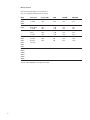
Memory allocation
The following table applies to instruments as
they were originally shipped from the factory.
Model
8561A,
8562A,
8562B
8560A,
8561B
8563A
8560E,
8561E,
8562E,
8563E,
8564E
8565E
8560EC,
8561EC,
8562EC,
8563EC,
8564EC,
8565EC
Serial prefix
<= 3040A
>= 3051A
Display RAM
128 K
128 K
RAM
512 K
512 K
EEPROM
16 K
16 K
UBEPROM
3M
4M
<=2925A
2928A-3204A
>= 3206A
<=2925A
3207A
>=3216A
<=3305A
>=3310A
Firmware
>=931216
128 K
128 K
128 K
128 K
128 K
128 K
128 K
128 K
128 K
640 K
1.2 M
1.2 M
640 K
1.2 M
1.2 M
1.2 M
4M
4M
16 K
16 K
16 K
16 K
16 K
16 K
16 K
16 K
64 K
4M
4M
8 M*
4M
4M
8 M*
12 M*
12 M*
12 M*
All
128 K
4M
64 K
12 M*
*Includes 4 M for 85629B test and adjustment module.
26
(This page intentionally left blank)
27
www.agilent.com
www.agilent.com/find/ad
Remove all doubt
www.agilent.com/find/emailupdates
Get the latest information on the
products and applications you select.
Agilent Direct
www.agilent.com/find/agilentdirect
Quickly choose and use your test
equipment solutions with confidence.
www.agilent.com/find/open
Agilent Open simplifies the process
of connecting and programming
test systems to help engineers
design, validate and manufacture
electronic products. Agilent offers
open connectivity for a broad range
of system-ready instruments, open
industry software, PC-standard I/O
and global support, which are
combined to more easily integrate
test system development.
Our repair and calibration services will
get your equipment back to you, performing like new, when promised. You
will get full value out of your Agilent
equipment through-out its lifetime.
Your equipment will be serviced by Agilent-trained technicians using the latest factory calibration procedures, automated repair diagnostics and genuine
parts. You will always have the utmost
confidence in your measurements.
For information regarding self maintenance of this product, please
contact your Agilent office.
Agilent offers a wide range of additional expert test and measurement
services for your equipment, including
initial start-up assistance, onsite education and training, as well as design,
system integration, and project management.
For more information on repair and
calibration services, go to:
www.agilent.com/find/removealldoubt
Product specifications and descriptions
in this document subject to change
without notice.
For more information on Agilent
Technologies’ products, applications
or services, please contact your local
Agilent office. The complete list is
available at:
www.agilent.com/find/contactus
Americas
Canada
Latin America
United States
(877) 894-4414
305 269 7500
(800) 829-4444
Asia Pacific
Australia
China
Hong Kong
India
Japan
Korea
Malaysia
Singapore
Taiwan
Thailand
1 800 629 485
800 810 0189
800 938 693
1 800 112 929
0120 (421) 345
080 769 0800
1 800 888 848
1 800 375 8100
0800 047 866
1 800 226 008
Europe & Middle East
Austria
01 36027 71571
Belgium
32 (0) 2 404 93 40
Denmark
45 70 13 15 15
Finland
358 (0) 10 855 2100
France
0825 010 700*
*0.125 €/minute
Germany
07031 464 6333
Ireland
1890 924 204
Israel
972-3-9288-504/544
Italy
39 02 92 60 8484
Netherlands
31 (0) 20 547 2111
Spain
34 (91) 631 3300
Sweden
0200-88 22 55
Switzerland
0800 80 53 53
United Kingdom 44 (0) 118 9276201
Other European Countries:
www.agilent.com/find/contactus
Revised: March 24, 2009
© Agilent Technologies, Inc. 2004, 2009
Printed in USA, April 14, 2009
5989-1216EN