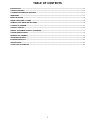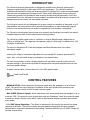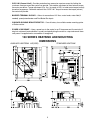
1
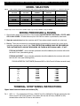
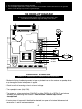
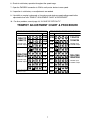
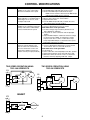
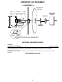
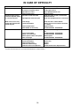
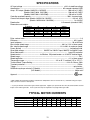
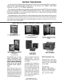
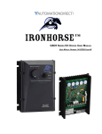
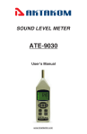
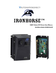
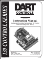
130 CONTROL SERIES
LT52 (0208)
CONTROLS
Instruction Manual
Cycling and Reversing Variable Speed DC Control
with on Board Dynamic Braking
P.O. Box 10
5000 W. 106th Street
Zionsville, Indiana 46077
Phone (317) 873-5211
Fax (317) 873-1105
www.dartcontrols.com
A-5-3159F
Quick Jump
What models and options are available?
See page 4.
Looking for detailed specifications?
See page 11.
Want to get started fast?
See basic electrical hook-up details on page 6.
See mechanical installation details on page 3.
Need Help?
See troubleshooting on page 10.
Warranty
Dart Controls, Inc. (DCI) warrants its products to be free from defects in material and workmanship. The exclusive remedy
for this warranty is DCI factory replacement of any part or parts of such product which shall within 12 months after delivery
to the purchaser be returned to DCI factory with all transportation charges prepaid and which DCI determines to its satisfaction
to be defective. This warranty shall not extend to defects in assembly by other than DCI or to any article which has been
repaired or altered by other than DCI or to any article which DCI determines has been subjected to improper use. DCI assumes
no responsibility for the design characteristics of any unit or its operation in any circuit or assembly. This warranty is in lieu
of all other warranties, express or implied; all other liabilities or obligations on the part of DCI, including consequential
damages, are hereby expressly excluded.
NOTE: Carefully check the control for shipping damage. Report any damage to the carrier immediately. Do not attempt to
operate the drive if visible damage is evident to either the circuit or to the electronic components.
All information contained in this manual is intended to be correct, however information and data in this manual are subject
to change without notice. DCI makes no warranty of any kind with regard to this information or data. Further, DCI is not
responsible for any omissions or errors or consequential damage caused by the user of the product. DCI reserves the right
to make manufacturing changes which may not be included in this manual.
WARNING
Improper installation or operation of this control may cause injury to personnel or control failure. The control must
be installed in accordance with local, state, and national safety codes. Make certain that the power supply is
disconnected before attempting to service or remove any components!!! If the power disconnect point is out of sight,
lock it in disconnected position and tag to prevent unexpected application of power. Only a qualified electrician or
service personnel should perform any electrical troubleshooting or maintenance. At no time should circuit continuity
be checked by shorting terminals with a screwdriver or other metal device.
TABLE OF CONTENTS
INTRODUCTION .......................................................................................................................................................................... 2
CONTROL FEATURES ................................................................................................................................................................ 2
130 SERIES HEATSINK AND MOUNTING ................................................................................................................................. 3
DIMENSIONS ............................................................................................................................................................................... 3
MODEL SELECTION .................................................................................................................................................................... 4
WIRING PROCEDURE & FUSING ............................................................................................................................................... 4
TERMINAL STRIP WIRING INSTRUCTIONS .............................................................................................................................. 4
130 HOOK-UP DIAGRAM ............................................................................................................................................................ 6
CONTROL START-UP .................................................................................................................................................................. 6
TRIMPOT ADJUSTMENT CHART & PROCEDURE ................................................................................................................... 7
CONTROL MODIFICATIONS ....................................................................................................................................................... 9
SPEEDPOT KIT ASSEMBLY ....................................................................................................................................................... 9
OPTION DESCRIPTIONS ............................................................................................................................................................. 9
IN CASE OF DIFFICULTY .......................................................................................................................................................... 11
SPECIFICATIONS ...................................................................................................................................................................... 11
TYPICAL MOTOR CURRENTS ................................................................................................................................................. 11
uld circuit continuity be checked by shorting terminals with a screwdriver or other metal device.
1
INTRODUCTION
·
The 130 series reversing speed control is designed to provide instant reversing, quick precise
stopping or rapid cycling for a wide range of DC motor applications. The 130 series controls
outperform other dynamic braking and reversing controls by utilizing Dart’s unique zero speed detect
and solid state assisted dynamic braking circuits. These circuits eliminate the contact arcing and
failed braking problems associated with other reversing and dynamic braking controls. Dart’s zero
speed detect circuit also eliminates the motor problems associated with plug reversing a motor by not
reapplying power to the motor until zero speed is obtained.
·
The 130 series controls are also designed so that upon a power loss condition to the control or an Estop condition, the control will drop into a dynamic brake condition to safely and quickly bring the
motor to a stop and remain there until power is reapplied and a run condition is recognized.
·
The 130 series variable speed control come in an extremely small package size and fits the industry
standard footprint for both vertical and horizantal mounting patterns.
·
The 130 series variable speed control is available in a range of 500mA through 10Adc output at
120Vac or 240Vac input. This represent a Horsepower range of 1/50 through 1 at 90Vdc out or 1/25
through 2 at 180Vdc out.
·
The control is designed for DC Permanent Magnet and Shunt Wound motors in the above
horsepower ranges.
·
Incoming AC voltage is converted to adjustable full wave rectified DC voltage to operate the DC
motor. Also, a full wave field voltage is provided for shunt wound motors.
·
The control incorporates transient voltage protection with adjustable current limit which fits into a
compact package. It also features adjustable IR compensation along with adjustable minimum and
maximum speeds settings.
·
Available softstart option. (Consult factory for your OEM specific needs)
·
Listed, file #E78180
CONTROL FEATURES
·
MINIMUM SPEED - Allows adjustment of the motor speed when the speedpot is set at minimum
(CCW). This permits the user to eliminate “Deadband” on the main speed control, permitting zero
calibration. Clockwise rotation of “MIN” trimpot increases speed.
·
MAX SPEED (Maximum Speed) - Allows adjustment of the motor speed when the speedpot is set at
maximum (CW). This permits the user to eliminate the top end “Deadband”, which will provide full speed
at maximum rotation. Rotation of the “MAX” trimpot in the clockwise direction increases the maximum
motor speed.
· I.R. COMP (Speed Regulation) - This allows for adjustment of the circuitry that controls the speed
regulation of the motor. The circuitry controls armature speed by changing the armature voltage to
compensate for increased or decreased motor loading. Clockwise rotation of the “IR COMP” trimpot will
increase compensation.
2
·
CUR. LIM. (Current Limit) - Provides protection from excessive armature current by limiting the
maximum armature current the control can provide. This enables adjustment of the maximum torque
the motor can deliver. Torque adjustment (Cur. Lim.) is preset at 125% of rated motor torque (current)
based on horsepower. Clockwise rotation of the “CUR. LIM.” trimpot increases the torque (current)
the control will provide.
·
BARRIER TERMINAL BLOCKS - Allows for connection of AC lines, motor leads, motor field (if
needed), speed potentiometer and Fwd-Brake-Rev inputs.
·
ONBOARD DYNAMIC BRAKE RESISTOR - Consult factory for available remote mounting option
of Brake resistor.
·
POWER LOSS BRAKE - Upon a power loss to the control or an E-stop command, the control will
drop into a dynamic brake condition to safely and quickly bring the motor to a stop and remain there
until power is reapplied and a run condition is recognized.
130 SERIES HEATSINK AND MOUNTING
DIMENSIONS
AUXILIARY HEATSINK -HS(125D)
STANDARD HEATSINK
CAUTION:
3
DO NOT MOUNT WHERE AMBIENT TEMPERATURE IS OUTSIDE THE RANGE OF -10o C (15o F) TO 45o C (115o F)
MODEL SELECTION
NOTE:
* With suitable external heatsink (where 130 extrusion temperature does not exceed 70° C.), maximum rating for
INPUT
VOLTAGE
120 VAC
120 VAC
120 VAC
120 VAC
240 VAC
240 VAC
240 VAC
240 VAC
OUTPUT
VOLTAGE
0-90 VDC
0-90 VDC
0-90 VDC
0-90 VDC
0-180 VDC
0-180 VDC
0-180 VDC
0-180 VDC
MODEL
NUMBER
130LC12
130LC100
130HC12
130HC100
132LC25
132LC200
132HC25
132HC200
OUTPUT*
AMPS DC
1.2 ADC
5.5 ADC*
1.2 ADC
10 ADC*
1.2 ADC
5.5 ADC*
1.2 ADC
10 ADC*
HORSEPOWER
1/50 – 1/8
1/8 – 1/2*
1/50 – 1/8
1/8 – 1
1/25 – 1/4
1/4 – 1*
1/25 – 1/4
1/4 – 2
Output Amps can be increased to 10 ADC output at up to 1Hp at 90VDC or 2Hp at 180VDC.
WIRING PROCEDURE & FUSING
1. Size all wires which carry armature or line currents AS SPECIFIED BY NATIONAL, STATE, AND/
OR LOCAL CODES. All other wires may be # 18 AWG or smaller as permitted by local code.
2. Separate control wires from the armature and AC lines when routed in conduit or in wire trays.
3. Fusing - The motor and control are protected against overloads by the current limit circuit and a
customer installed fuse in the AC line. THIS PROTECTION ALREADY MAY BE PROVIDED BY
THE CUSTOMER WITH CIRCUIT BREAKERS OR FUSES IN BOTH MAIN LINES. IF NOT:
FOR 120 VAC INPUT - fuse or breaker protection should be added by the customer inline with
the Hot AC Line (see following chart).
FOR 240 VAC INPUT - fuse or breaker protection should be added by the customer inline with
both Hot AC Lines (see following chart).
FUSING ADDED BY CUSTOMER (Bussman ABC or Little Fuse 314 Series ceramic fuses)
HORSEPOWER
1/50
1/20
1/8
¼
1/3
½
¾
1.0
1.5
2.0
120 VAC INPUT
2 AMP
2 AMP
3 AMP
4 AMP
6 AMP
8 AMP
12 AMP
15 AMP
-------------------
240 VAC INPUT
---------1 AMP
2 AMP
3 AMP
3 AMP
4 AMP
6 AMP
8 AMP
12 AMP
15 AMP
TERMINAL STRIP WIRING INSTRUCTIONS
Upper board terminal block connections (P4)
P4-1
(AC1 / L) – For single phase AC lines, (120VAC for US or 240VAC for Europe) connect the Hot
side of your AC line to this terminal. For systems with two hot AC lines, (240VAC for US)
connect either of the Hot AC lines to this terminal.
4
P4-2
(AC2 / N) – For single phase AC lines, (120VAC for US or 240VAC for Europe) connect the
Neutral side of your AC line to this terminal. For systems with two hot AC lines, (240VAC for
US) connect either of the Hot AC lines to this terminal.
P4-3
(A1) – For clockwise rotation of your motor in the Fwd. Direction, connect the Plus (+) Armature
wire of the motor to this terminal.
P4-4
(A2) – For counter-clockwise rotation of your motor in the Rev. direction, connect the Minus (-)
Armature wire of the motor to this terminal.
P4-5
(REV) – This is the reverse direction input terminal. When connected to the COM terminal, the
control will release its brake circuit and accelerate to its set point in the reverse direction. When
the connection to the COM terminal is opened the control will brake to zero speed. The
connection to the COM terminal can be made via a mechanical switch, a relay contact, or an
ungrounded solid state open collector type switch. Switching requirements are 5VDC at less
than 1ma.
P4-6
(FWD) – This is the forward direction input terminal. When connected to the COM terminal, the
control will release its brake circuit and accelerate to its set point in the forward direction. When
the connection to the COM terminal is opened the control will brake to zero speed. The
connection to the COM terminal can be made via a mechanical switch, a relay contact, or an
ungrounded solid state open collector type switch. Switching requirements are 5VDC at less
than 1ma.
P4-7
(COM) – This is the common terminal for the forward and reverse speed/dynamic brake
commands. This terminal should not be grounded or tied to any other terminal.
Lower board terminal block connections (P1)
P1-4
P1-5
(-A/-F) – DO NOT use for Permanent Magnet Motor. This supplies -Field voltage for a SHUNT
WOUND MOTOR (refer to field voltage table). For motors with dual voltage field (ie. 50/100V or
100/200V), make sure highest value is connected. Note: When connecting to this terminal, you
will need to use a fork or ring connector placed directly under the screw head.
(+F) – DO NOT use for Permanent Magnet Motor. This supplies +Field voltage for a SHUNT
WOUND MOTOR (refer to field voltage table). For motors with dual voltage field (ie. 50/100V or
100/200V), make sure highest value is connected.
FIELD VOLTAGE TABLE
VAC INPUT
120
240
VDC FIELD
100
200
P1-6
(Speedpot Hi) – Connects to high side (white wire) of Speedpot (CW end). This is an internal
+12VDC. For start-stop applications, the connection between this terminal and Speedpot HI can
be opened and closed by a SPST switch. INPUT MUST NOT BE GROUNDED!
P1-7
(Speedpot Wiper) – Connects to wiper (red wire) of Speedpot (center lead). For Voltage Follower
applications, this INPUT MUST NOT BE GREATER THAN +12V MAXIMUM AND MUST NOT
BE GROUNDED!
P1-8
(Speedpot Lo) – Connects to Low side (orange wire) of 5K Speedpot (CCW end). This input is
raised and lowered by the MIN. trimpot (5K). Electronic speed input (voltage follower) may be
referenced to Speedpot LO if the MIN trimpot adjustments are to be active. Otherwise, inputs
may be referenced to -ARM, which will bypass the MIN trimpot. INPUT MUST NOT BE
GROUNDED!
5
Warning:
1. Be sure the control housing is properly grounded.
2. For non-speedpot applications, the input connection to the LO, WIPER, and HI terminals must not be grounded!
Serious control damage may result from a grounded input.
130 HOOK-UP DIAGRAM
Warning:
Do not attempt to perform Hi-pot test across AC lines with control in circuit.
This will result in immediate or long term damage to the control.
SPEEDPOT
LO
W
HI
-8
-7
-6
LO
W
HI
SPDT
-7
P4
COM
-6
FWD
-5
REV
-4
A2
-3
A1
-2
~
N
~
L
-1
MOTOR
VAC INPUT
VAC INPUT
P1
CONTROL START-UP
WARNING: ALL POWER MUST BE TURNED OFF BEFORE PROCEEDING!
1. Recheck all wiring. Accidental grounds to loose or pinched wires on the armature or speedpot wires
may damage the control when power is applied.
2. Check to see that incoming service is of correct voltage.
3. Turn speedpot to zero (fully CCW).
4. Turn power on, close contact from COM(P4-7) to either FWD(P4-6) or REV(P4-5) and advance
speedpot while observing motor rotation. Power must be off before step 5 can be
accomplished!
5. If motor rotation is incorrect for the direction selected, turn power off at external disconnect and
reverse the A1 and A2 motor connections.
6
6. Check for satisfactory operation throughout the speed range.
7. Open the FWD/REV connection to COM to verify motor brakes to zero speed.
8. If operation is satisfactory, no readjustments are needed.
9. If instability or surging is observed, or if maximum and minimum speed settings need further
adjustments then see “TRIMPOT ADJUSTMENT CHART & PROCEDURE”.
10. For other problems, consult page 10, “IN CASE OF DIFFICULTY”.
TRIMPOT ADJUSTMENT CHART & PROCEDURE
Settings apply when using a 5K ohm master speedpot. This chart is used
in conjunction with the adjustment procedure and is approximate.
C.L.
I.R.
MAX
MIN
Settings apply when using a 5K ohm master speedpot. This chart is used
in conjunction with the adjustment procedure and is approximate.
HP
HP
130LC12
130HC12
1/50
1/20
1/20
1/8
120 VAC input;
0-90 VDC output
1/8
1/4
1/8
1/4
1/4
1/3
1/3
1/2
1/2
3/4*
3/4*
1.0*
1.0*
1.5*
Operation of the control beyond ±10% of the normal line voltage could result
in re-adjustment. These adjustments are permanent; periodic re-adjustment
is normally not needed.
2.0*
130LC100
130HC100
120 VAC input;
0-90 VDC output
7
C.L.
I.R.
MAX
MIN
132LC25
132HC25
240 VAC input;
0-180 VDC output
132LC200
132HC200
240 VAC input;
0-180 VDC output
CONTROL MODIFICATIONS
TRIMPOT
MIN.
FUNCTION
Sets minimum motor speed when
speedpot is set at zero. CW rotation
will increase minimum motor speed.
IR COMP
Provides a means of improving motor
speed regulation. If a slowdown due to
load change is of no concern, rotate
this trimpot fully CCW.
MAX.
Sets maximum motor speed when
speedpot is set at maximum (fully CW
rotation). CW rotation of MAX trimpot
increases maximum motor speed.
CUR.LIM.
Limits DC motor armature current
(torque) to prevent damage to the
motor or control. The current limit is
set for the rated motor current. CW
rotation of this trimpot increases the
armature current (or torque produced).
TWO SPEED OPERATION USING
TWO 10K SPEEDPOTS
ADJUSTMENT
1. Select a direction and set Speedpot to zero (fully CCW).
2. Rotate MIN trimpot CW until motor starts to rotate
3. Slowly rotate MIN trimpot CCW until motor stops.
NOTE: If motor rotation is desired, rotate MIN trimpot
CW until desired MIN speed is reached
1. Select a direction and set Speedpot at 50%.
2. Observe motor speed at no load condition.
3. Apply full load to motor.
4. Turn IR COMP trimpot CW until you obtain the same
motor speed as the no load condition.
1. TURN DRIVE POWER OFF!!
2. Connect a DC Voltmeter across A1 and A2.
NOTE: Meter must not be grounded!!
3. Set meter voltage range if needed: (90 VDC for 120
VAC, 180VDC for 240 VAC).
4. Turn power on. Select a direction and set Speedpot
at100%.
5. Adjust the MAX trimpot to rated motor armature voltage
as shown on meter. NOTE: A tachometer or strobe
may be used in lieu of a meter. Follow above steps,
except adjust MAX trimpot to rated motor base speed
indicated by tachometer or strobe.
1. TURN DRIVE POWER OFF!
2. Connect a DC Ammeter between A1 on motor and A1
on the control. This is in series with the motor.
NOTE: Meter must not be grounded!!
3. Turn power on.
4. Select a direction and set Speedpot at the 50% position.
5. Apply friction braking to motor shaft until motor stalls.
6. With motor stalled, set current at 125% of rated motor
armature current by adjusting CUR. LIM . trimpot.
TWO SPEED OPERATION USING
TWO 5K SPEEDPOTS
P1
LO
-8
HI
-7
LO
W
W
P1
H
HI
HI
-7
DPDT SWITCH
-6
INHIBIT
P1
-8
LO
-7
WIPER
SPEEDPOT
SPST
-6
W
W
-8
-6
LO
LO
SPDT
HI
8
HI
SPEEDPOT KIT ASSEMBLY
CUSTOMER'S
MOUNTING BRACKET
DIALPLATE
2.00" dia.
1.240
.500
.370
SPEEDPOT
KNOB
.370
HEX NUT
1.250
.250 Dia.
LOCK
WASHER
SPEEDPOT
(5K 2W)
.437
5/32
DIA.
3/8
DIA
SPEEDPOT LOCATOR HOLE DIMENSIONS
OPTION DESCRIPTIONS
-K option
Acceleration Time Ranges
Factory Installed
This option provides the Accel time shown below. The standard Accel time is 0.5 seconds.
ACCELERATION TIME------------------------------------------------------------------------------------------ 6
seconds
USE STANDARD HOOK-UP
9
IN CASE OF DIFFICULTY
PROBLEM
Motor doesn’t operate
Armature output voltage
cannot be adjusted, output
is a constant DC level
Motor stalls, or runs very
slowly with speed control
turned fully CW
Motor hunts
Repeated fuse blowing
POSSIBLE CAUSE(S)
- Blown Fuse or Breaker
- Incorrect or no power source
- Speedpot set at Zero
- Worn motor brushes
- No motor or load connected
- Speedpot low connection open
- Low Voltage
- Overload Condition
- Worn motor brushes
- MAX SPEED set incorrectly
- Motor current less than 150Ma
- Too much IR COMP
- Motor is in current limit
- Motor speed is above rated speed
- Max set too high
- Low Voltage
- Overload Condition
- Worn motor brushes
- Defective motor bearings
- Defective electrical components
CORRECTIVE ACTION(S)
Replace Fuse or reset breaker
Install proper service
Adjust Speedpot CW to start
Replace brushes
Check that motor or load is connected to
armature terminals
Check that speedpot low wire is connected
Check that VAC is above 100VAC
Reduce load or increase motor size and/or
C.L. setting.
Replace brushes
See ADJUSTMENT PROCEDURE
Motor current must be greater than 150mA
D.C.
See ADJUSTMENT PROCEDURE
See ADJUSTMENT PROCEDURE
Reduce Speed
See ADJUSTMENT PROCEDURE
Check that VAC is above 100VAC
Reduce load
Replace
Replace
Call Dart Distributor or Representative
If control still will not operate, consult your Dart Distributor or Representative.
10
SPECIFICATIONS
AC input voltage --------------------------------------------------------------------------- ±10% of rated line voltage
Acceleration ------------------------------------------------------------------------------- 0.5 seconds standard 125D
Amps - DC output; (Models 130XX12 & 132XX25) --------------------------------------- 500 mA to 1.2 ADC
(Models 130LC100 & 132LC200) ------------------------------------ 500 mA to 5.5 ADC*
(Models 130HC100 & 132HC200) ------------------------------------ 500 mA to 10 ADC
Controller overload capacity ------------------------------------------------------------------- 200% for one minute
Current limit trimpot range; (Models 130XX12 & 132XX25) ------------------------------------- 0.3 to 3 ADC
(Models 130XX100 & 132XX200) ----------------------------------- 1 to 18 ADC
Deceleration
0.5 seconds (standard 125D)
Dimensions and weights:
LC MODELS
ENGLISH
METRIC
HC MODELS
ENGLISH
METRIC
W
4.967”
126.16mm
W
6.250”
158.75mm
L
4.250”
107.95mm
L
7.000”
177.80mm
D
2.688”
68.27mm
D
4.063”
103.20mm
WEIGHT
1.08lb.
489.87g
WEIGHT
3.30lb.
1496.80g
Drive service factor ------------------------------------------------------------------------------------------------------ 1.0
Efficiency ------------------------------------------------------------------------------------------------------- 85% typical
Input frequency -------------------------------------------------------------------------------------------- 50 or 60 Hertz
Max. trimpot speed range ------------------------------------------------------------ 60% to 110% of base speed
Min. trimpot speed range ---------------------------------------------------------- 0% to 30% of maximum speed
Power devices ----------------------------------------------------------------------------------------- isolated case tab
Shunt field voltage ----------------------------------- 100VDC for 120VAC input; 200VDC for 240VAC input
Shunt field current -------------------------------------------------------------------------------- 1 amp DC maximum
Speed control ---------------------------------- via 5Kohms .5W potentiometer or 0-10VDC isolated signal
Speed range ------------------------------------------------------------------------------------------------------------- 50:1
Speed regulation ----------------------------------------------------------------------------------- ±1% of base speed
Temperature range -------------------------------------------------------- -10° to 45° C. ambient (15° to 115° F.)
Terminal Block Torque Setting -------------------------------------------------------------- 4.4 in. lb. Max or .5Nm
Transient protection ------------------------------------------------------------------------------------------------ G-Mov
Trigger ---------------------------------------------------------------------------------------------------------- opto-isolator
Start/Brake cycle per minute (LC Models) ---------------------------------------------------------------- 3 per min**
(HC Models) -------------------------------------------------------------- 30 per min**
Approval -------------------------------------------------------------------------------------------------------
* With suitable external heatsink (where 130 extrusion temperature does not exceed 70° C.), maximum rating for output
amps can be increased to 10 amps D.C.
** Cycles per minute are based on typical inertia type loads. Higher cycle per minute rates may be achieved with constant
torque or low inertia type loads. Lower cycle rates may be required for very high inertia type loads.
TYPICAL MOTOR CURRENTS
Horsepower
Typical AC Amps (120VAC)
Typical Arm Amps (120VAC)
Typical AC Amps (240VAC)
Typical Arm Amps (240VAC)
1/50
0.50
0.42
---------
1/20
1.00
0.81
0.80
0.40
1/8
2.00
1.60
1.20
0.60
1/4
3.50
2.70
1.80
1.40
11
1/3
4.40
3.40
2.20
1.70
1/2
6.50
5.00
3.30
2.50
3/4
9.30
8.20
4.80
3.70
1.0
13.20
10.90
6.50
5.00
1.5
--------9.70
8.20
2.0
--------12.90
11.60
- Notes -
12
- Notes -
13
REPAIR PROCEDURE
In the event that a Product manufactured by Dart Controls Incorporated (DCI) is in need of
repair service, it should be shipped, freight paid, to: Dart Controls, Inc., 5000 W. 106th Street,
Zionsville, IN. 46077, ATTN: Repair Department.
Those orders received from anyone without and existing account with DCI will need to specify
if they will be paying COD or Credit Card (Master Card or Visa). This information is required
before work can begin. If you have an account with Dart your order will be processed according
to the terms listed on your account.
Completed repairs are returned with a Repair Report that states the problem with the control
and the possible cause. Repair orders are returned via UPS Ground unless other arrangements
are made. If you have further questions regarding repair procedures, contact your Dart Controls,
Inc. at 317-733-2133 Ext.460.
YOUR MOTOR SPEED CONTROL SOLUTIONS PROVIDER
125D SERIES
AC INPUT - VARIABLE DC OUTPUT
1/50 HP through 1.0 HP
700/COMMUTROL SERIES
DC BRUSHLESS
5 & 20 Amp for
12,24,& 36VDC Inputs
Dart Controls, Inc. is a designer, manufacturer, and
marketer of analog and digital electronic variable speed
drives, controls, and accessories for AC, DC, and DC
brushless motor applications.
Shown above is just a sampling of the expanded line of
Dart controls that feature the
latest in electronic technology
and engineering. Products are
manufactured in the U.S.A. at
our Zionsville (Indianapolis,
250G SERIES
65 SERIES
AC INPUT - VARIABLE DC OUTPUT
1/50 HP through 2.0 HP
DC INPUT - VARIABLE DC OUTPUT
CURRENT RATINGS OF 20, 40, AND
60 AMPS
MDP SERIES
PROGRAMMABLE
CLOSED LOOP DC
SPEED CONTROL
Indiana) production and headquarters facility - with over
2,000,000 variable speed units
in the field.
In addition to the standard offthe-shelf products, you can select from a wide variety of options to customize controls for
your specific application. For
further information and application assistance, contact your
local Dart sales representative, stocking distributor, or
Dart Controls, Inc.
www.dartcontrols.com
ISO9001:2000 REGISTERED
DM SERIES
FIELD PROGRAMMABLE
DIGITAL TACHOMETER
Dart Controls, Inc.
Manufacturer of high quality DC and AC motor speed
controls and accessories
since 1963.
P.O. Box 10
5000 W. 106th Street
Zionsville, Indiana 46077
Phone: (317) 733-2133
Fax: (317) 873-1105