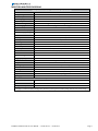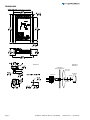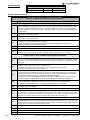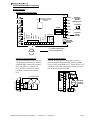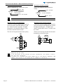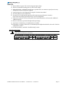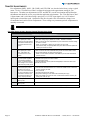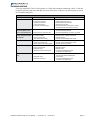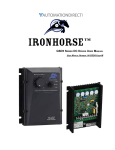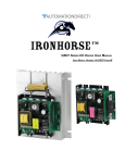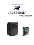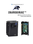
1
™
GSD6 Series DC Drives User Manual
User Manual Number: IH-GSD6-User-M
IronHorse GSD6 DC Drives User Manual – 1st Ed, Rev B – 02/06/2014
Page 1
~ WARNING ~
Thank you for purchasing automation equipment from Automationdirect.com®, doing business as AutomationDirect. We want your new automation equipment to operate safely. Anyone who installs or uses this equipment
should read this publication (and any other relevant publications) before installing or operating the equipment.
To minimize the risk of potential safety problems, you should follow all applicable local and national codes that
regulate the installation and operation of your equipment. These codes vary from area to area and usually change
with time. It is your responsibility to determine which codes should be followed, and to verify that the equipment,
installation, and operation is in compliance with the latest revision of these codes.
At a minimum, you should follow all applicable sections of the National Fire Code, National Electrical Code,
and the codes of the National Electrical Manufacturer’s Association (NEMA). There may be local regulatory or
government offices that can also help determine which codes and standards are necessary for safe installation and
operation.
Equipment damage or serious injury to personnel can result from the failure to follow all applicable codes
and standards. We do not guarantee the products described in this publication are suitable for your particular
application, nor do we assume any responsibility for your product design, installation, or operation.
Our products are not fault-tolerant and are not designed, manufactured or intended for use or resale as on-line
control equipment in hazardous environments requiring fail-safe performance, such as in the operation of
nuclear facilities, aircraft navigation or communication systems, air traffic control, direct life support machines,
or weapons systems, in which the failure of the product could lead directly to death, personal injury, or severe
physical or environmental damage (“High Risk Activities”). AutomationDirect specifically disclaims any
expressed or implied warranty of fitness for High Risk Activities.
For additional warranty and safety information, see the Terms and Conditions section of our catalog. If you have
any questions concerning the installation or operation of this equipment, or if you need additional information,
please call us at 770-844-4200.
This publication is based on information that was available at the time it was printed. At AutomationDirect we
constantly strive to improve our products and services, so we reserve the right to make changes to the products
and/or publications at any time without notice and without any obligation. This publication may also discuss
features that may not be available in certain revisions of the product.
Trademarks
This publication may contain references to products produced and/or offered by other companies. The product
and company names may be trademarked and are the sole property of their respective owners. AutomationDirect
disclaims any proprietary interest in the marks and names of others.
Copyright © 2013, 2014 Automationdirect.com® Incorporated
All Rights Reserved
No part of this manual shall be copied, reproduced, or transmitted in any way without the prior, written consent of
Automationdirect.com® Incorporated. AutomationDirect retains the exclusive rights to all information included
in this document.
Page 2
IronHorse GSD6 DC Drives User Manual – 1st Ed, Rev B – 02/06/2014
Contents
WARNING ��������������������������������������������������������������������������������������������������������������������������������������������������������������������������������������������������� 2
Trademarks������������������������������������������������������������������������������������������������������������������������������������������������������������������������������������������������ 2
GSD6 DC Drives User Manual Overview ���������������������������������������������������������������������������������������������������������������������������������������������� 3
IronHorse GSD6 Series DC Drives General Information ������������������������������������������������������������������������������������������������������������������ 4
Selection and Specifications������������������������������������������������������������������������������������������������������������������������������������������������������������������ 5
Dimensions ������������������������������������������������������������������������������������������������������������������������������������������������������������������������������������������������ 6
Installation and Wiring������������������������������������������������������������������������������������������������������������������������������������������������������������������������� 7
Start-Up���������������������������������������������������������������������������������������������������������������������������������������������������������������������������������������������������� 11
Trim Pot Adjustments���������������������������������������������������������������������������������������������������������������������������������������������������������������������������� 12
Troubleshooting������������������������������������������������������������������������������������������������������������������������������������������������������������������������������������ 13
GSD6 DC Drives User Manual Overview
Overview of this Publication
The IronHorse GSD6 Series DC Drives User Manual describes the installation, configuration, and
methods of operation of the GSD6 Series DC Drives.
All information contained in this manual is intended to be correct. However, information and data in this
manual are subject to change without notice. AutomationDirect (ADC) makes no warranty of any kind
with regard to this information or data. Further, ADC is not responsible for any omissions or errors or
consequential damage caused by the user of the product. ADC reserves the right to make manufacturing
changes which may not be included in this manual.
Who Should Read This User Manual
This manual contains important information for those who will install, maintain, and/or operate any of the
GSD6 Series DC Drives.
Technical Support
By Telephone: 770-844-4200 (Mon.–Fri., 9:00 a.m.–6:00 p.m. E.T.)
On the Web: www.automationdirect.com
Our technical support group is glad to work with you in answering your questions. If you cannot find
the solution to your particular application, or, if for any reason you need additional technical assistance,
please call Technical Support at 770-844-4200. We are available weekdays from 9:00 a.m. to 6:00 p.m.
Eastern Time.
We also encourage you to visit our web site where you can find technical and non-technical information
about our products and our company. Visit us at www.automationdirect.com.
Special Symbols
When you see the “notepad” icon in the left-hand margin, the paragraph to its
immediate right will be a special note.
When you see the “exclamation mark” icon in the left-hand margin, the paragraph to its immediate right
will be a WARNING. This information could prevent injury, loss of property, or even death (in extreme
cases).
IronHorse GSD6 DC Drives User Manual – 1st Ed, Rev B – 02/06/2014
Page 3
IronHorse GSD6 Series DC Drives General Information
IronHorse GSD6 DC drives are versatile, general-purpose, variable-speed, DC motor controllers that
are designed to control DC Permanent Magnet, Shunt Wound, and some Universal (AC/DC) motors.
Incoming AC voltage is converted to adjustable full-wave rectified DC voltage to operate the DC motor.
Also, a full-wave field voltage is provided for shunt wound motors.
Carefully check the DC Drive for shipping damage. Report any damage to the
carrier immediately. Do not attempt to operate the drive if visible damage is
evident to either the circuit or to the electronic components.
Standard Features
• Input voltages 115/230VAC @ 50/60Hz; output 0–90/180VDC.
• Barrier terminal strip for all power and control wiring.
• Full-wave packaged bridge supply.
• 1% speed regulation with armature voltage feedback; ±1/2% with tachometer feedback.
• Adjustable Minimum speed, Maximum speed, IR Compensation, Current Limit, and Acceleration &
Deceleration.
• Line voltage compensation.
• 5kΩ speed potentiometer with leads, dial, and knob included.
• 50:1 speed range.
• Transient voltage protection.
• Voltage following mode or DC tachometer follower by supplying ungrounded 0–12VDC analog input
signal.
• DC tachometer feedback (jumper selectable 3V or 7V per 1,000 rpm).
• Inhibit circuit permits start & stop without breaking AC lines.
• Shunt field supply provided.
• Includes two AC line fuses.
• 12 VDC 12 mA user-accessible power supply
• Open-frame chassis.
Control Features
MINIMUM SPEED – Allows adjustment of the motor speed when the speed pot is set at minimum
(CCW). This permits the user to eliminate “Deadband” on the main speed control, permitting zero
calibration.
MAX SPEED (Maximum Speed) – Allows adjustment of the motor speed when the speed pot is set at
maximum (CW). This permits the user to eliminate the top end “Deadband”, which will provide full
speed at maximum rotation.
ACCEL (Acceleration) – Allows adjustment of the motor acceleration time.
DECEL (Deceleration) – Allows adjustment of the motor deceleration time.
I.R. COMP (Speed Regulation) – Adjusts the drive output to compensate for speed changes caused by
varying motor loads. As motor load is increased, IR COMP increases the voltage output of the drive.
CUR. LIM. (Current Limit) – Provides protection from excessive armature current by limiting the
maximum armature current the drive can provide. This enables adjustment of the maximum torque the
motor can deliver.
INPUT SELECTION SWITCH – Switch selectable between 115VAC and 230VAC input
TACH INPUT SELECTION – Jumper selectable between 3V and 7V per 1,000 rpm (preset for 3V).
Page 4
IronHorse GSD6 DC Drives User Manual – 1st Ed, Rev B – 02/06/2014
Selection and Specifications
GSD6 Series DC Drives – Selection & Specifications
Model
Package Configuration
GSD6-240-15C
open frame
1.4
Power Quality Form Factor
Input Voltage (@50/60Hz)
Output Voltage
Shunt Field Voltage
Motor Rating (hp)
115/230 VAC ±10%
0–90/180 VDC
100VDC @ 115VAC input ; 200VDC @ 230VAC input ; (1.5A max)
1/8 – 1.5 hp @ 90VDC ; 1/4 – 3 hp @ 180VDC
15A (DC)
Output Current (continuous)
Current Overload Capacity
Current Limit (adjustable)
Transient Protection
200% for 60s
2–30A (DC)
Metal Oxide Varistor (MOV)
I.R. Compensation
1.5hp and 3hp
Speed Adjustment
5kΩ 0.5W potentiometer
50:1
Speed Range
Speed Regulation
±1% of base speed
Maximum Speed
adjustable from 60% to 120% of base speed
Minimum Speed
linear ramp 0–30% of adjustable maximum speed
Acceleration
linear ramp adjustable 0.3–12 seconds
Deceleration
adjustable 0.6–12 seconds
no
Dynamic Braking
Plugging Capability **
no
Electrical Connections
barrier-type terminal strip; 26–12 AWG
Fusing
Operating Temperature
Thermal Protection
Mounting Orientation
Corrosive Gases
Weight
(2) 20A fuses included (Bussman ABC-20 or Littlefuse 314020 ceramic fuses or equivalent)
-10 to 45 °C [14 to 113 °F]
not available
can be mounted in any orientation
NOT compatible with any corrosive gases
40 oz [1134g]
RoHS
Agency Approvals
Optional Accessories *
Replacement Potentiometer
GSDA-5K
Digital Potentiometer
GSDA-DP
Analog Current Input Card
GSDA-AI-A
* For accessories details, please visit www.AutomationDirect.com.
** Plugging is a method of rapidly changing motor direction by reversing motor armature polarity, while the motor is still running.
IronHorse GSD6 DC Drives User Manual – 1st Ed, Rev B – 02/06/2014
Page 5
Dimensions
GSD6-240-15C (dimensions = in [mm])
Speed Pot
Mounting
Speed Pot
CUSTOMER’S
MOUNTING BRACKET
DIALPLATE
(2-inch dia)
SPEEDPOT
SPEEDPOT
KNOB
HEX NUT
LOCK
WASHER
Page 6
IronHorse GSD6 DC Drives User Manual – 1st Ed, Rev B – 02/06/2014
Installation and Wiring
Install open-frame drives in an enclosure with a volume at least three
times the volume of the open-frame drive.
Do not mount GSD6-240-15C DC drive where ambient temperature is outside
the range of -10 to 45 °C (14 to 113 °F).
Size all wires that carry armature or line currents as specified by applicable national, state, and/or local codes. All other wires may be
20AWG or smaller as permitted by the codes.
Separate control wires from the armature and AC lines when routed in
conduit or wire trays.
CAUTION!! Turn power OFF while making wiring connections.
Improper installation or operation of this DC Drive may cause injury to personnel or drive
failure. The drive must be installed in accordance with local, state, and national safety codes.
Make certain that the power supply is disconnected before attempting to service or remove any
components!!! If the power disconnect point is out of sight, lock it in disconnected position
and tag it to prevent unexpected application of power. Only a qualified electrician or service
personnel should perform any electrical troubleshooting or maintenance. At no time should
circuit continuity be checked by shorting terminals with a screwdriver or other metal device.
Before attempting to wire the DC Drive, make sure all power is disconnected. Recheck code
designation to assure proper voltage is present for the DC Drive. Carefully select proper wire
size for current and voltage drop. Limit the voltage drop through the wiring to 5% of the line
voltage at full load
CAUTION!! Do not attempt to perform a hi-pot test across the AC lines with the DC drive in
the circuit. This will result in immediate or long-term damage to the drive.
1) Ensure that the GSD6 drive chassis is properly grounded.
2) Motor armature connections must not be switched or broken while the GSD6 drive is ON.
Serious damage may result.
3) The inputs to the speed pot terminals (P2-3, P2-4, P2-5) must not be grounded.
Serious damage may result.
Fusing
The GSD6 has a 20A internal fuse in each AC line (P1-2 & P1-3), and this fuse is sized to open in the
event of a shorted armature or if an armature line is shorted to earth ground. Both AC lines are fused.
For replacement, use Bussman ABC-20 or LittleFuse 314-020.
(AutomationDirect sells ABC series fuses.)
AC current is determined by motor characteristics, and it may be necessary to increase fuse value for some applications.
230V
For 208–240 VAC inputs, slide the selector
switch completely to the right, as shown below:
115V
Input Voltage Switch Selection
For 110–130 VAC inputs, slide the selector
switch completely to the left, as shown below:
CAUTION!! An incorrect setting of the input VAC selector switch will result in damage to the
drive.
IronHorse GSD6 DC Drives User Manual – 1st Ed, Rev B – 02/06/2014
Page 7
Wiring Terminals
GSD6 Wiring Terminals
Type
Wire Range
Tightening Torque
barrier-type terminal strip
26–12 AWG
10.0 lb·in [1.1 N·m]
Wiring Terminal Functions
GSD6 Series DC Drives – Terminal Strip Functions
CAUTION: BE SURE DRIVE HOUSING IS PROPERLY GROUNDED.
Number
Purpose
P1 – Terminal Strip for Power Wiring
P1-1
(EARTH GROUND) – Ground the drive by connecting the ground wire to this terminal. NOTE: Terminals P1-5 (-ARM)
and P2-2 (AMP REF) are electrically the same, which is the common reference point (low voltage common) for the
control logic. The EARTH GROUND terminal (P1-1) is electrically different from common. If connected together,
either at the amplifier or in any other fashion, fatal or hazardous operation may occur and permanent damage to the
drive WILL result!
P1-2
(AC1) 115VAC – Connect incoming hot AC (black wire) to this terminal. NOTE: This is fused (F1) on the drive.
(AC1) 230VAC – Connect either hot side.
P1-3
(AC2) 115VAC – Connect the neutral AC (white wire) to this terminal. NOTE: This is fused (F2) on the drive.
(AC2) 230VAC – Connect either hot side.
P1-4
(+ ARMATURE) – Connects to the plus (+) Armature wire on the motor. 0-90VDC for 115VAC input or 0-180VDC for
230 VAC input. See “SPECIFICATIONS” for output rating.
CAUTION: ARMATURE CONNECTION MUST NOT BE SWITCHED OR BROKEN WHILE DRIVE IS ON,
OR SERIOUS DAMAGE TO THE DRIVE MAY RESULT.
P1-5
(- ARMATURE) – Connects to minus (-) Armature wire (also considered circuit common) on the motor.
P1-6
(- FIELD) – Connect minus (-) Field wire of the Shunt Wound motor (not used on PM motors).
P1-7
(+ FIELD) – DO NOT use for Permanent Magnet motor. This supplies + Field voltage for a Shunt Wound motor.
For motors with dual voltage field (ie. 50/100V or 100/200V), make sure the highest value is connected.
P2 – Terminal Strip for Control Wiring
CAUTION: NONE OF THE P2 TERMINALS SHOULD BE EARTH GROUNDED!
Page 8
P2-1
(OVER CURRENT OUT) – Can be used to signal that the drive is in current limit. It can also signal other devices or
alarms. This is a low level logic signal which goes “high” when the current limit amplifier is in current limit. The logic
of this drive is +12 volts, while the output at this terminal is approximately 1.5 volts through a 1000W resistor when in
Current Limit.
P2-2
(AMP REF) – This is the common point of the logic. It is used as common with OVER CURRENT OUT (P2-1),
+TACH (P2-9), REV 1 (P2-7), REV 2 (P2-8), and WIPER (P2-4).
NOTE: Never connect this terminal to earth ground !! Serious damage and injury may result !!
This terminal is electrically the same point as -ARM (P1-5).
P2-3
(SPEEDPOT LO) – Connects to the low side (orange wire) of the 5kΩ Speed Pot (normally the CCW end). This input
is raised and lowered by the MIN trim pot. Electronic speed input voltage (voltage follower) may be referenced to
Speed Pot LO if the MIN trim pot adjustments are to be active. Otherwise, inputs may be referenced to AMP REF
(P2-2), which will bypass the MIN trim pot. INPUT MUST NOT BE GROUNDED !
CAUTION FOR VOLTAGE FOLLOWER APPLICATIONS: THE INPUT CONNECTION TO THE Speed pot MUST
NOT BE GROUNDED !! SERIOUS DAMAGE TO THE DRIVE MAY RESULT FROM A GROUNDED INPUT.
P2-4
(SPEEDPOT WIPER) – Connects to the wiper (red wire) of the Speed Pot (center lead). Use this input for the plus
(+) side of voltage follower operation or tach follower. The minus (-) side connects to AMP REF (P2-2).
INPUT MUST NOT BE GREATER THAN +12V MAXIMUM AND MUST NOT BE GROUNDED !
P2-5
(SPEEDPOT HI) – Connects to high side (white wire) of the Speed Pot (CW end). This is internal +12 volts.
INPUT MUST NOT BE GROUNDED !
P2-6
(SPARE) – This terminal is not connected to the drive circuit. It can be used as a terminal for field modifications.
P2-7
(REV 1) – REV 1 and REV 2 are identical quick stop inputs. One of them must be held low (to AMP REF) before the
drive will operate. The two are diode separated to form an “OR” gate. Since -ARM (P1-5) is also low in the system,
these two inputs can be wired to the motor side of a reversing switch or relay. During the period of switching, neither
input will be low, which will instantly return the set speed to zero and reset the acceleration ramp.
P2-8
(REV 2) – Identical to REV 1 (P2-7).
P2-9
(+TACH) – Connect +Tach from a DC tachometer for tachometer feedback. The minus (-) lead from the tachometer
goes to AMP REF (P2-2). Output voltage from the tachometer at full speed can range from 6 to 12 volts. The scale
is corrected using the JU3 jumper selectable setting of 3V/7V per 1000 rpm and the MAX speed trim pot. A 3-volt per
1000 rpm OR 7-volt per 1000 rpm tachometer should be used.
P2-10
(PILOT LIGHT) – Connecting point for on-off neon indicator lamp. The remaining lead will be connected to P2-11.
P2-11
Reserved
P2-12
Reserved
P2-13
Reserved
IronHorse GSD6 DC Drives User Manual – 1st Ed, Rev B – 02/06/2014
Installation and Wiring (continued)
Wiring Diagrams
GSD6-240-15C Basic Wiring Diagram
P1
CUR LIM
P3
PROVIDES SUPPORT
AND TRIGGERING FOR
OPTIONS
IR COMP
-3
-4 -5
orange
red
-6
-7
COMMON
PILOT LAMP
-9 -10 -11 -12 -13 P2
START
-8
STOP
+TACH
REV 1
SPARE
POT HI
POT WIPER
-2
POT LO
-1
JUMPER WIRE (JU2)
not active
REV 2
MIN
AMP REF
ACCEL
OVER CUR OUT
DECEL
FUSES
RELAY
+FIELD
-6
-FIELD
-5
-ARM
-4
+ARM
-3
AC (N)
VAC INPUT
-2
AC (L)
VAC INPUT
-1
GND
EARTH
GROUND
115V
MAX
OPTIONAL:
FOR SHUNT
WOUND
MOTORS ONLY
-7
DC MOTOR
+
–
INPUT
VOLTAGE
SELECTOR
SWITCH
white
= customer supplied wiring
= factory supplied wiring
SPEEDPOT
GSD6-240-15C Two-Speed Operation
GSD6-240-15C Dynamic Braking
Two-speed operation is done using two
10 kΩ speed potentiometers in parallel,
with both Highs connected to terminal
P2-5, and both Lows connected to
P2-3. A SPDT switch selects which
pot Wiper is connected to terminal
P2-2.
A DPDT switch is used to control and to connect a
customer-supplied Dynamic Braking Resistor (DBR).
Typical values for the DBR are 35–50W at 5Ω for 115V,
or 10Ω for 230V. Motor horsepower, inertia, and cycle
time affect the sizing of the DBR.
P2
(2) 10kΩ Speedpots
GSD6-240-15C
4
W
SPDT
W
HI
W
LO
LO
3
LO
HI
HI
5
+TACH
IronHorse GSD6 DC Drives User Manual – 1st Ed, Rev B – 02/06/2014
P2
3
4
5
6
7
8
9
DPDT
MOTOR
4 5
DYNAMIC
BRAKE
RESISTOR
P1
Page 9
Installation and Wiring – Wiring Diagrams (continued)
GSD6-240-15C Tachometer Feedback
GSD6-240-15C Tachometer Follower
Improves regulation to ± 1/2% of base speed.
Allows drive output to follow tachometer
voltage.
P2-9 +Tach
+
Tachometer
–
6/12 VDC at Base Speed
(3/7 VDC at 1000 rpm for
1800 rpm motor)
P2-4 Pot Wiper
+
Tachometer
P1-5 -Arm / Amp Ref
12 VDC at Full Speed
–
P2-3 Pot Lo
Tachometer control needs tachometer output ripple limited to 1% or less.
GSD6-240-15C Inhibit (used independently)
GSD6-240-15C Inhibit (used with speed pot)
Connect the customer-supplied SPST switch in
series between the Speed Pot High (P2-5) and
the +Tach (P2-9) drive terminals. To inhibit
(stop motor), close Speed Pot High to +Tach.
To restart, return the switch to open.
Connect the customer-supplied SPST switch in
series between Speed Pot High the drive Speed
Pot High terminal (P2-5). To inhibit (stop
motor), open the SPST switch. To restart, close
the switch.
The drive will stop and start the motor quickly.
The drive will soft stop and soft start the motor
through the acceleration setting.
P2
3
WIPER 4
5
HI
6
7
8
+TACH 9
P2
LO
SPEEDPOT
SPEEDPOT
3
LO
4
WIPER
5
HI
SPST
SPST
1) Inhibit control permits starting and stopping the motor without
breaking the AC lines.
2) In the event of SCR failure or false triggering, the Inhibit circuit
will not stop the motor.
3) Always use shielded wire when connecting to the Inhibit terminal, and
connect the shield to the -Armature or Common of the drive.
Page 10
IronHorse GSD6 DC Drives User Manual – 1st Ed, Rev B – 02/06/2014
Start-Up
1) Ensure that the 115/230 VAC is set for the proper input voltage.
2) Check to see that the incoming power is of the correct voltage.
3) Recheck all wiring. Accidental grounds, loose or pinched wires on armature or speed pot wires may
damage the DC drive when power is applied.
4) Preset trim pots for your horsepower by using the “Trim Pot Preset Chart”.
5) Turn the speed pot to zero (fully CCW).
6) Turn power on, and advance the speed pot while observing motor direction of rotation.
Power must be turned off again before step 7 can be accomplished!
7) If the motor rotation is incorrect, turn power off at external disconnect, and reverse the +ARM and
-ARM connections.
8) Check for satisfactory operation throughout the speed range.
9) If operation is satisfactory, no readjustments are needed.
10) If instability or surging is observed, or if maximum speed is higher than desired, refer to the “Trim Pot
Adjustments” section.”
11) For other problems, consult the “Troubleshooting” section.
Trim Pot Preset Chart
When making adjustments, always use a screwdriver with an insulated shaft to avoid
short-circuiting PC board components.
MIN
ACCEL DECEL MAX
I.R. CUR LIM
HP
1.5
VOLTS
MIN
ACCEL DECEL MAX
120
I.R. CUR LIM
HP
VOLTS
3.0
240
NOTES: These settings apply when using a 5kΩ speedpot.
IronHorse GSD6 DC Drives User Manual – 1st Ed, Rev B – 02/06/2014
Page 11
Trim Pot Adjustments
Four adjustments (MIN., MAX., I.R. COMP., and CUR. LIM.) are checked at the factory using a typical
motor. Use the “Trim Pot Preset Chart” to adjust the trim pots to the approximate setting for your
horsepower. The other two adjustments (ACCEL and DECEL), are the Acceleration and Deceleration
adjustments and should be set for your particular application requirements. The “Trim Pot Preset Chart”
is approximate, and is valid when using a speed pot, a 0–12 VDC input signal, or a 0–10V isolated
input signal to control the speed. Operation of the drive beyond ±10% of normal line voltage is not
recommended and could result in readjustments. These settings are permanent; periodic readjustment is
normally not needed.
Use only an ungrounded voltmeter
For GSD6 Drives without Analog Current/Voltage Input Cards
GSD6-240-15C Trim Pot Adjustment *
Trim Pot
Function
Adjustment
Max
Sets maximum motor speed
when speed pot is set at
maximum (fully CW rotation).
CW rotation of MAX trim pot
increases maximum motor
speed.
1) Connect a DC voltmeter: + to +ARM; - to -ARM.
2) Set meter voltage range: (90VDC for 115VAC; 180VDC for 230VAC).
3) With no load on the motor, adjust MAX trim pot to rated motor armature voltage
as shown on meter.
NOTE: A tachometer or strobe may be used in lieu of a meter.
Follow above steps, except adjust MAX trim pot to rated motor base speed indicated by tachometer or strobe.
Min
Sets minimum motor speed
when speed pot is set at
zero. CW rotation will
increase minimum motor
speed.
1) Set Speed Pot to zero (fully CCW).
2) With no load on the motor, rotate MIN trim pot CW until motor starts to rotate.
3) Slowly rotate MIN trim pot CCW until motor stops.
NOTE: If motor rotation is desired, rotate MIN trim pot CW until desired MIN
speed is reached.
IR Comp
Provides a means of improving motor speed regulation
in the armature feedback
mode. If a slowdown due to
load change is of no concern,
rotate this trim pot fully CCW.
1) Set Speed Pot at 50%.
2) Observe motor speed at no load condition.
3) Apply full load to motor.
4) Turn IR COMP trim pot CW (with load still applied) to obtain the same motor
speed as with no load.
Cur Lim
Limits DC motor armature
current (torque) to prevent
damage to the motor or
drive. The current limit is set
for 125% rated motor current.
CW rotation of this trim pot
increases the armature current (or torque produced).
1) TURN DRIVE POWER OFF!
2) Connect a DC Ammeter between +A on motor and +ARM on drive. Preset the
Current Limit trim pot CCW.
3) Turn power ON.
4) Set Speed Pot at the 50% position.
5) Apply friction braking to motor shaft until motor stalls (zero rpm).
6) With motor stalled, set current at 125% of rated motor armature current by adjusting CUR. LIM. trim pot.
Accel
Allows adjustment of acceleration by user.
1) CW rotation of the ACCEL trim pot increases acceleration time.
Decel
Allows adjustment of deceleration by user.
1) CW rotation of the DECEL trim pot increases deceleration time.
* DO NOT USE this adjustment procedure for GSD6-240-15C DC drives with GSDA-AI-A analog current input cards.
Page 12
IronHorse GSD6 DC Drives User Manual – 1st Ed, Rev B – 02/06/2014
Troubleshooting
If a newly installed DC Drive will not operate, it is likely that a terminal connection is loose. Check the
terminal connections and ensure that they are secure and correct. If the drive is still inoperative, refer to
the Troubleshooting Table.
Troubleshooting
Problem
Possible Cause(s)
Corrective Action
Motor doesn’t run
1)
2)
3)
4)
5)
1)
2)
3)
4)
5)
Armature output voltage
cannot be adjusted; output is a constant DC level
1) No motor or load connected
Blown fuse or circuit breaker
Incorrect or no power
Speed Pot set at zero
Worn motor brushes
Improper or missing jumper
Replace fuse or reset breaker
Install proper power service
Rotate Speed Pot CW to start
Replace motor brushes
Ensure that jumper JU2 is properly connected between drive terminals P2-2 and P2-7
2) Speed Pot low connection open
1) Ensure that motor or load is connected to armature terminals
2) Ensure that Speed Pot Low wire is connected
Motor stalls, or runs very
slowly with speed control
set fully CW
1)
2)
3)
4)
1)
2)
3)
4)
Motor “hunts”
1) Too much IR Comp
2) Motor is in Current Limit
3) Motor speed is above rated speed
1) Consult “Trim Pot Adjustments” section
2) Consult “Trim Pot Adjustments” section
3) Reduce Max trim pot setting
Repeated fuse blowing
1)
2)
3)
4)
1)
2)
3)
4)
Motor runs, but will not
stop
1) Incorrect wiring (enclosed drive)
Low voltage
Overload condition
Worn motor brushes
Max speed set incorrectly
Overload condition
Worn motor brushes
Defective motor
Defective electrical components
2) Defective wiring
3) Defective component
Ensure that VAC is above 104 or 208 VAC
Reduce load or re-adjust Current Limit
Replace brushes
Consult “Trim Pot Adjustments” section
Reduce load
Replace brushes
Replace motor
Contact AutomationDirect “Product Returns” for replacement.
1) Ensure that Terminal Strip Wiring is correct per wiring instructions/diagrams
2) Check wiring
3) Contact AutomationDirect “Product Returns” for replacement.
IronHorse GSD6 DC Drives User Manual – 1st Ed, Rev B – 02/06/2014
Page 13
BLANK
PAGE
Page 14
IronHorse GSD6 DC Drives User Manual – 1st Ed, Rev B – 02/06/2014
BLANK
PAGE
IronHorse GSD6 DC Drives User Manual – 1st Ed, Rev B – 02/06/2014
Page 15
Literature Number: LT145
Drawing Number: A-5-3904A
Page 16
IronHorse GSD6 DC Drives User Manual – 1st Ed, Rev B – 02/06/2014