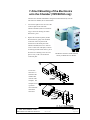
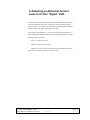
1
IC Plus Electronics Unit YMCS0004 and YMCS0005 Operating and Service Manual OXFORD DANFYSIK Unit 1 Ferry Mills, Osney Mead Oxford, OX2 0ES UK Tel: +44 (0) 1865 320 300 Fax: +44 (0) 1865 320 301 http://www.oxford-danfysik.com [email protected] IC Plus Electronics Unit OPERATING AND SERVICE MANUAL Version: 6 Date:8 Nov 2002 Page 1 of 16 Table of Contents 1. KEY FEATURES ...............................................................................................................................3 2. DETAILED SPECIFICATIONS......................................................................................................5 3. 4. 5. 2.1 2.2 2.3 2.4 2.5 PREAMPLIFIER ................................................................................................................................5 VOLTAGE TO FREQUENCY CONVERTER.........................................................................................6 HIGH VOLTAGE SUPPLY WITH LCD DISPLAY ................................................................................6 RS 232 COMMUNICATION PORT ....................................................................................................7 USER INPUTS & OUTPUTS ..............................................................................................................7 2.6 2.7 POWER REQUIREMENTS..................................................................................................................7 BLOCK DIAGRAM OF THE ELECTRONICS .......................................................................................8 FRONT PANEL DESCRIPTION ....................................................................................................9 3.1 LOCAL / REMOTE OPERATION - ADDRESS SELECTION...................................................................9 3.2 3.3 3.4 HIGH VOLTAGE SETTING & DISPLAY .............................................................................................9 INPUT RANGE SELECTION & DISPLAY ............................................................................................9 INPUT OFFSET ADJUSTMENT & DISPLAY ........................................................................................9 DESCRIPTION OF THE CONNECTORS ..................................................................................10 4.1 4.2 4.3 4.4 4.5 INPUT CURRENT ...........................................................................................................................10 HIGH VOLTAGE SUPPLY ..............................................................................................................10 PREAMPLIFIER OUTPUT ................................................................................................................10 VOLTAGE TO FREQUENCY CONVERTER OUTPUT .........................................................................10 RS 232 COMMUNICATION PORT ..................................................................................................10 4.6 USER INPUTS & OUTPUTS - 24 VDC POWER SUPPLY ..................................................................10 REMOTE CONTROL SOFTWARE.............................................................................................12 5.1 5.2 INTRODUCTION ............................................................................................................................12 DESCRIPTION................................................................................................................................12 5.3 5.4 5.5 5.6 5.7 COMMANDS LIST ..........................................................................................................................13 SYNTAX RULES.............................................................................................................................14 CONNECTING WITH A HOST COMPUTER .......................................................................................14 IC PLUS DEMO INSTALLATION WITH WINDOWS ......................................................................15 NETWORK CONFIGURATION .........................................................................................................15 6. DIRECT MOUNTING OF THE ELECTRONICS ONTO THE CHAMBER (YMCS0004 ONLY).......................................................................................................................................................17 7. DETECTING AN ABNORMAL CURRENT LEAK ON IC PLUS “SIGNAL” PATH .........18 8. WARRANTY ....................................................................................................................................19 9. SOFTWARE LICENCE AGREEMENT AND LIMITED WARRANTY................................20 9.1 LICENCE AGREEMENT..................................................................................................................20 9.2 LIMITED WARRANTY ...................................................................................................................20 IC Plus Electronics Unit OPERATING AND SERVICE MANUAL Version: 6 Date:8 Nov 2002 Page 2 of 16 1. Introduction Dear Customer, Thank you for your purchase of this equipment, we hope that you will find it easy to set-up and use. If you have questions, comments or suggested improvements, please do not hesitate to contact us. We will be glad to hear from you. Good luck with your experimental program ! Initial Setup On receiving this equipment you should have the following items; • Electronics module • Signal and High Voltage Cables (if you have purchased the stand alone module YMCS0004) • Mains power supply. • This manual. • Floppy disc with demo communication software. Please read this manual before connecting the electronics module. IC Plus Electronics Unit OPERATING AND SERVICE MANUAL Version: 6 Date:8 Nov 2002 Page 3 of 16 2. Key Features The IC Plus X-ray beam intensity monitors are a range of ionization chambers that offer premium performance at very low cost. Four models are available : the IC Plus 50, the IC Plus 150, and the IC Plus 300 which vary only in the length of the body and electrodes, and a very short version: the IC Plus 10 which is similar in style but has one valve on the base of the unit. The IC Plus ELECTRONICS module is a front-end compact module designed to offer maximum low current measurement stability, minimise noise due to ground loops and permit remote control and measurements through a RS232 communication port. In the case of part number YMCS0004, it mounts directly on the detector body (except for the IC Plus 10) or, for the YMCS0005, it connects to the chamber through high quality coaxial cables (only OXFORD DANFYSIK certified cables should be used: otherwise noise and stability specifications could not be guaranteed). It features current measurement ability from 100 fA to 0.1 mA in 6 ranges: • Range 1: 0.1 pA to 1 nA • Range 2: 1 pA to 10 nA • Range 3: 10 pA to 0.1 µA • Range 4: 0.1 nA to 1 µA • Range 5: 1 nA to 10 µA • Range 6: 10 nA to 0.1mA with 2 analogue outputs: • voltage output from 0 to 10 V • frequency output from to 0 to 1 MHz It can operate either in LOCAL or REMOTE mode (selected on the front panel): • In LOCAL mode, the user can select, from the front panel, the 3 measurement configuration parameters (polarisation voltage, current range and input offset) very easily by using an UP/DOWN switch and 3 parameter selection switches. • In REMOTE mode, the address of the device has to be selected from 0 to 15 using the 4 front panel address micro-switches. IC Plus Electronics Unit OPERATING AND SERVICE MANUAL Version: 6 Date:8 Nov 2002 Page 4 of 16 3. Detailed Specifications 3.1 Preamplifier • Input impedance: 1000 GΩ // 1 pF. Input is protected against High Voltage breakdown through ionization chamber electrodes • Typical input bias current: 20 fA below 0°C, 100 fA at 25°C, 300 fA at 40°C • Typical input offset current temperature drift : 6 fA / °C between 0 and 30°C • Low frequency (0.1 to 10 Hz) current input noise: 10 fA peak to peak max on range 1 (highest gain range) • Input offset voltage average drift: 1 µV / °C typical, 5 µV / °C max • Long term offset stability: 15 µV / month • Integration capacitor: 100 pF ± 0.5 %, temperature coefficient -25 ppm / °C typical • Integration time: Range 1: 1 second Range 2: 100 ms Range 3: 5 ms Range 4: 1 ms Range 5: 100 µs Range 6: 10 µs • Full scale output voltage : 10 volts • Output impedance: 50 Ω, short circuit protected. A 50 Ω coaxial cable (up to 150 ft/45 m long) should be used to connect the voltage output to a high input impedance remote voltmeter or acquisition system (any input impedance lower than 1 MΩ will induce a gain error). IC Plus Electronics Unit OPERATING AND SERVICE MANUAL Version: 6 Date:8 Nov 2002 Page 5 of 16 3.2 Voltage to Frequency Converter • Non-linearity: 0.1% typical (100Hz to 1 MHz) • Temperature drift: ± 150 ppm / °C typical at 100 kHz • Output impedance: 50 Ω, short circuit protected. 3.3 High Voltage Supply with LCD display Caution : LETHAL VOLTAGE PRESENT INSIDE DEVICE AND ON HIGH VOLTAGE OUTPUT PIN OR SOCKET WHEN OPERATED: 1700 VOLTS MAXIMUM High Voltage supply . DEVICE MUST NOT BE CONNECTED TO ITS POWER SUPPLY CONNECTOR BEFORE IT IS COMPLETELY MOUNTED OR CONNECTED TO THE IONIZATION CHAMBER INSTALLED ON THE EXPERIMENT. Shielding ground warning : In order to obtain the best signal shielding, the body of the ionization chamber must always be electrically connected to the ground of the IC Plus Electronics device used. This condition is normally achieved if a piggy-back IC Plus Electronics device is attached to an IC Plus ionization chamber according to the mounting instructions described in Section 7, or if OXFORD DANFYSIK certified HV and Signal coaxial cables are used to connect a BNC/SHV IC Plus Electronics device to an IC Plus ionization chamber. • Adjustable from 0 to 1700 V in one-volt steps • Maximum output current: 1.2 mA (short-circuit protected) • HF noise: 1 mV peak to peak typical • LF noise: 4 mV peak to peak typical • Temperature drift: 20 ppm / °C typical • 3 1/2 digit miniature LCD for actual HV output value display IC Plus Electronics Unit OPERATING AND SERVICE MANUAL Version: 6 Date:8 Nov 2002 Page 6 of 16 3.4 RS 232 Communication Port • Transfer rate: 9600 Baud • Enables daisy-chain connection of up to 16 modules • Enables remote configuration, measurement retrieval and user I/Os control 3.5 • User Inputs & Outputs Three 50 KΩ impedance inputs (default logic value = 1 if input NC) suitable for: - contact reading (must be referred to 0 V): CLOSE = logic level zero - logic level voltage reading: 0 V for logic 0, 3 V min for logic 1 • Three PNP open collector outputs: 500 mA, one lead connected to ground. Common supply of 30 VDC max to be injected from outside the module (see section 4.6 for details). 3.6 Power requirements 24 Volts DC nom (23 V min - 27 V max), 150 mA nominal current. This is supplied by a mains adapter (provided) which requires a mains supply voltage of 90 V – 260 V AC. 50-60 Hz. IC Plus Electronics Unit OPERATING AND SERVICE MANUAL Version: 6 Date:8 Nov 2002 Page 7 of 16 3.7 INPUT SIGNAL Block Diagram of the Electronics High Precision Current Integrator Voltage Output Voltage to Frequency Converter Frequency Output 28 bit A/D Delta/Sigma Converter Micro Controller HIGH VOLTAGE OUTPUT Low Noise High Voltage Supply User’s I/Os Front Panel Keys and Displays IC Plus Electronics Unit OPERATING AND SERVICE MANUAL RS232 Port PSU Version: 6 Date:8 Nov 2002 Page 8 of 16 4. Front Panel Description 4.1 Local / Remote Operation - Address selection High Voltage, Input Range and Input Offset values are displayed on front panel whatever mode is selected; • Local operation: enables High Voltage, Input Range and Input Offset values selection from front panel. • Remote operation: selectable only from front panel "Local / Remote" switch; see sections 5.5 and 6 for details. 4.2 High Voltage setting & display Select "High Voltage" on the front panel "High Voltage / Input" switch. Use the "Up / Down" switch to change value. The output Voltage is displayed in volts 4.3 Input Range selection & display Select "Input" on the front panel "High Voltage / Input" switch and "Range" on the "Range / Offset %" switch. Use the "Up / Down" switch to change range. Range number (from 1 to 6) is displayed on the LED 7-segment display. 4.4 Input Offset adjustment & display Enables positive frequency shift on the 0-1MHz output. Select "Input" on the front panel "High Voltage / Input" switch and "Offset %" on the "Range / Offset %" switch. Use the "Up / Down" switch to change value. Possible values : from 0 % to +99 %. Input offset is displayed in percentage of the Full Scale of the selected Input range on the lower 3 1/2 LCD. IC Plus Electronics Unit OPERATING AND SERVICE MANUAL Version: 6 Date:8 Nov 2002 Page 9 of 16 5. Description of the Connectors 5.1 Input Current YMCS0004: a pair of special customized ultra-low leakage insulated pins make connections for Input and Zero Volts, directly fitting the ionization chamber output (lower) electrode through rear panel (which replaces the connectors plate of the stand-alone ionization chamber), or on the YMCS0005 connection is made via a standard BNC socket and low noise cable. 5.2 High Voltage Supply YMCS0004: a special customized high withstand voltage insulated pin (standalone), directly fits the ionization chamber polarisation (upper) electrode through rear panel (which replaces the connectors plate of the stand-alone ionization chamber), or on the YMCS0005: connection is made via a SHV BNC socket and high voltage cable. 5.3 Preamplifier output LEMO ERN00 socket located at top left of IC Plus Electronics unit 5.4 Voltage to Frequency Converter output LEMO ERN00 socket located at top right of IC Plus Electronics unit 5.5 RS 232 Communication Port (see section 5 for more details) 9-pin male SUB-D socket located at bottom right of IC Plus Electronics unit: Pin2: RX from Computer - Pin3: TX to Computer Pin7: RX from other unit - Pin8: TX to other unit Pin5 is 0V ( = common = ground) 5.6 User Inputs & Outputs and 24 VDC Power supply 9-pin female SUB-D socket located at bottom left of the IC Plus Electronics unit: Pin5: 24 VDC supply input - Pin9: 0V ( = common = ground) Pin4: User Output 1 - Pin3: User Output 2 - Pin2: User Output 3 Pin1: DC positive supply (30 V max) for open collector User Outputs supply only IC Plus Electronics Unit OPERATING AND SERVICE MANUAL Version: 6 Date:8 Nov 2002 Page 10 of 16 Pin8: User Input 1 - Pin7: User Input 2 - Pin6: User Input 3 (caution: when User Inputs are not connected, internal pull-up resistors set their default digital values to 1) User’s I/Os connector: 2.5A FUSE Micro Controller Output Switching Transistors Pin 1 External DC supply from external equipment Pin 2 / 3 / 4 OUTPUTS to switched devices Pin 9 External DC supply return IC Plus Electronics Unit OPERATING AND SERVICE MANUAL Version: 6 Date:8 Nov 2002 Page 11 of 16 6. Remote Control Software 6.1 Introduction The IC Plus Electronics units can be remotely controlled by a host computer (PC or workstation) through a serial link (RS 232). A network of up to 16 units can be built, requiring only one serial port on the host computer. The communication protocol is a subset of the SCPI (Standard Commands for Programmable Instruments) language. 6.2 Description The IC Plus Electronics unit holds a C programmable sub-miniature controller. The program is factory stored in its FLASH Eprom. When "Remote" operation is selected on front panel, this program recognizes commands coming from a host computer and is therefore able to drive the unit: • by controlling its three configuration parameters: High Voltage, Selected Range, Input Offset Percentage, • by enabling Input Current value retrieval; it is encoded on 28 data bits, refered to a Full Scale value of 262 144 000, • by enabling remote control of three digital User Inputs and three digital User Outputs, • by resetting the unit to its default configuration parameters: - High Voltage = 0 volt - Selected Range = 6 - Input Offset % = 0 - User Outputs = 0 (the unit is reset at power on) Every unit has an address between 0 and 15 (4-bit encoding), selected by DIP switches on Front Panel, with weights 8, 4, 2 and 1 from left to right. Lower position of each switch is zero. For example, set the first and the third switches (from left side on) to select address 10. IC Plus Electronics Unit OPERATING AND SERVICE MANUAL Version: 6 Date:8 Nov 2002 Page 12 of 16 6.3 Command list *RSTad reset the unit :CONFad:VOLT x set HV to x value :CONFad:CURR:RANG x set Input Range to x :CONFad:CURR:OFFS x set Input Offset Percentage to x :CONFad:VOLT? read HV value :CONFad:CURR:RANG? read Input Range :CONFad:CURR:OFFS? read Input Offset Percentage :READad:CURR? read Input Current value (Full Scale = 262 144 000) :SENSad:STATx? read User input x (x = 0,1 or 2) :SOURad:STATx y set User Output x (x = 0,1 or 2) to y (y = 0 or 1) :SOURad:STATx? read User Output x (x = 0,1 or 2) ad (unit address): an integer value from 0 to 15 Values range for x parameter: high voltage integer from 0 to 1700 (DC volts) range integer from 1 (F.S. = 1 nA) to 6 (F.S. = 0.1 mA) Input Offset integer from 0 to +99 (%) User I/Os integer from 0 to 2 IC Plus Electronics Unit OPERATING AND SERVICE MANUAL Version: 6 Date:8 Nov 2002 Page 13 of 16 Examples :CONF3:VOLT 1500 set HV to 1500 V on address 3 unit :CONF12:CURR:OFFS 56 set Input Offset to 56% on address 12 unit :READ0:CURR? will return Input Current value of address 0 unit Note: The program waits for strings ending with a special character (Line Feed: ASCII code = 10). This character must be transmitted by the host computer. When the program returns a value, it also sends this character after the value. Every time this special character is acknowledged, the program sends a single character (ASCII code = 6) to the host computer. 6.4 Syntax rules Upper and lower case characters are accepted. 6.5 Connecting with a host Computer This unit can be connected to a RS232 port of a host computer. Only three wires are needed. See section 7.5 for connections description. If the host computer is a PC, pins 4, 6 and 8 must be tied together on the 9-pin SUB-D connector of the PC side of the cable. The following protocol is supported by the OXFORD DANFYSIK unit: - baud rate 9600 - data format 8 bits ASCII data and 1 stop bit - parity none CTS, RTS signals are disabled. The DEMO program provided by OXFORD DANFYSIK on the floppy disc supplied with the IC Plus Electronics unit runs under Windows on IBM PCs or compatible. It is a demonstration of communication with the unit. IC Plus Electronics Unit OPERATING AND SERVICE MANUAL Version: 6 Date:8 Nov 2002 Page 14 of 16 6.6 IC Plus Demo installation with Windows 1) Insert the floppy disk in drive A: 2) Click on the Start button and select Run. 3) Type a:setup and click on the OK button. 4) The default directory is C:\DEMO but you may change it. Then click on the Ok button. 5) After a while you will get the following message : Setup has installed the software successfully and added the application(s) to the Program Manager. Click on the OK button. 6) The demo is ready to run, you only have to click twice on the IC Plus icon. 6.7 Network configuration These units are designed to operate in a network made of several IC Plus Electronics units and/or Cyberstar X1000 pulse processing units. Up to 16 units of both types can be linked together using only one RS232 port of the host computer. When a unit is linked to the network, its address must not be already in use by any of the other units. The wiring for a network (including two units) connected to a PC, is detailed hereafter. PC connector B connector cable 1 Unit A connector 2 (RX) }- - - - -{ 3 (TX 0) 3 (TX) }- - - - -{ 2 (RX 0) 5 (ground) }- - - - -{ 5 (ground) }- - - - -{ 5 (ground) 7 (RX 1) }- - - - -{ 3 (TX 0) 8 (TX 1) }- - - - -{ 2 (RX 0) IC Plus Electronics Unit OPERATING AND SERVICE MANUAL cable 2 Unit Version: 6 Date:8 Nov 2002 Page 15 of 16 When the unit B is disconnected, pins 2 and 3 of the connector located at the end of cable 2 must be grounded with a 1000 Ohm resistor. When a unit is in local mode, it does not stop communication with other units in remote mode. IC Plus Electronics Unit OPERATING AND SERVICE MANUAL Version: 6 Date:8 Nov 2002 Page 16 of 16 7. Direct Mounting of the Electronics onto the Chamber (YMCS0004 only). The electronics module YMCS0004 is designed to be mounted directly onto the side of the ion chamber, this is described here. 1. Unscrew the eight H screws to remove the connector plate on the side of the ionization chamber (caution: watch the Oring), as shown on drawing ref YMCS 0001 sheet 3, part 1. 2. Replace the connectors plate by the IC Plus Electronics: gently insert the black connectors on the rear panel of the electronics into the inside pins of the ionization chamber, then screw three H screws on each side of the plate, as shown on drawing ref YMCS 0001 sheet 3, part 2. Store the two remaining screws in a safe place in case you have to remount the connectors plate. The IC Plus electronics module attached directly to the IC Plus ion chamber. The IC Plus electronics is attached to the chamber after removal of the side plate. The side plate is left is position when used with stand-alone electronics. IC Plus Electronics Unit OPERATING AND SERVICE MANUAL Version: 6 Date:8 Nov 2002 Page 17 of 16 8. Detecting an Abnormal Current Leak on IC Plus “Signal” Path An abnormal current leak through "Signal" path means that, when set to highest sensitivity, the IC Plus Electronics, working as a nano-ampere measurement device, will show a very high current offset with no beam through the ionization chamber, whatever the high voltage polarization value: to check this, just choose Range 1 (1 nA full scale) on the IC Plus Electronics unit connected to the ionization chamber; analog and digital outputs mean values should be equal or lower than: - 20 mV on "Analog out 0-10V", - 2 kHz on "Frequency out 0-1MHz", 500000 as "Current read-out" value displayed on the "IC Plus Electronics" demo software window when "Remote" mode is used . IC Plus Electronics Unit OPERATING AND SERVICE MANUAL Version: 6 Date:8 Nov 2002 Page 18 of 16 9. Warranty 1. OXFORD DANFYSIK warrants that the Equipment shall be free from defects by reason of faulty design, workmanship or materials and that if within the guarantee period set out in sub-clause 3 the Equipment proves defective for such reason OXFORD DANFYSIK shall adjust, repair or replace it as it sees fit free of charge, provided that: 1.1. The Equipment has been used solely for the purpose for which OXFORD DANFYSIK understands it is to be used and in accordance with the operating instructions; 1.2. The defect has not been caused by fire, accident, misuse, neglect, incorrect installation by the customer, its customers, agents or servants or unauthorised repair or maintenance or by use of sub-standard consumables; 1.3. The defect has not arisen from any design, specification, component or material supplied by the customer. 1.4. No part of the Equipment has been replaced with a part not supplied by OXFORD DANFYSIK or approved as suitable by it; 1.5. Payment in full or all sums due in respect of the Equipment has been made; 1.6. The customer shall be liable for any costs incurred by OXFORD DANFYSIK in responding to claims made in respect of erroneous results caused by operator error or incorrect application. 1.7. Upon the customer making a claim under sub-clause 1 it shall accord sufficient access to the Equipment to enable OXFORD DANFYSIK staff to inspect and adjust, repair, remove or replace the Equipment. 1.8. OXFORD DANFYSIK will co-operate with the customer in the assessment of reported defects by the final decision regarding the applicability of this guarantee shall rest with OXFORD DANFYSIK. 2. OXFORD DANFYSIK shall decide if the Equipment should be repaired pursuant to sub-clause 1 at its site or returned. 3. The applicable guarantee period shall be 12 months after delivery save where the Equipment is installed and/or commissioned by or under the supervision of OXFORD DANFYSIK in which case it shall be 12 months from the date of the installation certificate or 18 months after the date of delivery, whichever is the earlier. IC Plus Electronics Unit OPERATING AND SERVICE MANUAL Version: 6 Date:8 Nov 2002 Page 19 of 16 10. Software Licence Agreement and Limited Warranty 10.1 Licence Agreement As part of the sales package for the OXFORD DANFYSIK IC Plus Electronics unit, the customer will receive from OXFORD DANFYSIK a licence to use the accompanying software subject to the following terms and conditions; • • The sofware package may be used, without time limit, on one personal computer or workstation A separate licence agreement and fee is required for each additional personal computer or workstation on which the package is used. • The software package may not be duplicated or copied except for archive purposes or to replace defective media, and each copy made must bear the copyright notices carried on the original. The software package may not be transferred in any event to a third party unless written consent is obtained from OXFORD DANFYSIK. • This software package is protected under copyright law and OXFORD DANFYSIK reserves the right to terminate this licence upon any violation of these laws. In the event of termination, the customer will be required to return all copies of the software package to OXFORD DANFYSIK. • Some parts of the software package are specially protected in order to be read or modified only by OXFORD DANFYSIK engineers. Under no circumstances will OXFORD DANFYSIK be under obligation to disclose information relating to these parts of the software. 10.2 Limited Warranty The standard software is fully tested and under normal use is guaranteed to be free of bugs and defects on IC Plus Electronics units. The insurance is not valid for special software adaptations on non-standard electronics units. In this case, OXFORD DANFYSIK agrees to correct at its own expense, during a one year warranty period, any defect arising during the use of the modified software package. In no event will OXFORD DANFYSIK be liable for any direct or indirect incidental or consequential damages arising from a software failure. IC Plus Electronics Unit OPERATING AND SERVICE MANUAL Version: 6 Date:8 Nov 2002 Page 20 of 16