1
CREDITS/COPYRIGHT
Copyright © 2010 Stanley Security Solutions, Inc. All rights reserved.
Information in this document is subject to change without notice and does not
represent a commitment on the part of Stanley Security Solutions, Inc. The software
described in this document are furnished under a license agreement or nondisclosure
agreement.
This publication is intended to be an accurate description and set of instructions
pertaining to its subject matter. However, as with any publication of this complexity,
errors or omissions are possible. Please call your BEST® distributor or Stanley Security
Solutions, Inc. at (317) 849-2250 if you see any errors or have any questions. No part of
this manual and/or databases may be reproduced or transmitted in any form or by any
means, electronic or mechanical, including photocopying, recording, or information
storage and retrieval systems, for any purpose, without the express written permission
of Stanley Security Solutions, Inc.
This document is distributed as is, without warranty of any kind, either express or
implied, respecting the contents of this book, including but not limited to implied
warranties for the publication’s quality, performance, merchantability, or fitness for any
particular purpose. Neither Stanley Security Solutions, Inc., nor its dealers or
distributors shall be liable to the user or any other person or entity with respect to any
liability, loss, or damage caused or alleged to be caused directly or indirectly by this
publication.
HID and iCLASS are registered trademarks of HID Corporation.
Sargent is a registered trademark of Sargent Manufacturing Co.
TORX is a registered trademark of the Camcar Division of Textron.
Von Duprin is a registered trademark of Von Duprin, Inc.
Wi-Q is a trademark of Stanley Security Solutions, Inc.
Written and designed by Stanley Security Solutions, Inc. and Avalon Group, Inc.,
Indianapolis, Indiana.
T83338 Rev A ER7991-6 July 2010
CONTENTS
GETTING STARTED
1–1
Introduction 1–1
Product overview 1–2
Mortise lock overview 1–2
Cylindrical lock overview 1–3
Exit hardware trim overview 1–4
Documentation package
1–5
Technical support 1–6
Support services 1–6
Telephone technical support 1–6
STANDARD ESCUTCHEON COMPONENTS 2–1
Inside escutcheon
2–2
Magnetic stripe reader outside escutcheon
2–4
Proximity reader outside escutcheon 2–6
Dual validation reader outside escutcheon
MORTISE COMPONENTS
2–8
3–1
Inside trim components 3–2
Outside trim components
3–3
Mortise cases by function and option 3–4
Mortise case faceplates
3–5
Strike boxes and strike plates 3–6
Cylinder components 3–7
Other components 3–7
Stanley Wi-Q™ Technology Illustrated Parts Catalog
i
Contents
CYLINDRICAL COMPONENTS 4–1
Lever components 4–2
Levers 4–2
Standard lever components 4–3
Lever components for use with non-interchangeable cores
4–4
Trim components 4–5
Cylindrical chassis
Latches
4–6
4–7
Strike boxes and strike plates
4–8
Other components 4–9
EXIT DEVICE TRIM COMPONENTS
5–1
Exit hardware trim compatibility 5–2
Inside trim components 5–3
Magnetic stripe reader outside escutcheon
5–4
Proximity reader outside escutcheon 5–6
Dual validation reader outside escutcheon
5–8
Cylinders and related components 5–10
Mortise cylinder and related components 5–10
Rim cylinder and related components 5–11
Levers
5–12
Lift fingers 5–13
Other components 5–14
Changing the handing 5–15
FIELD SERVICE KITS
6–1
Field replacement kits 6–2
Reader kits 6–2
Control electronics kits 6–3
Wire harness kits for standard Wi-Q Locks 6–3
Internal part kits for EXQ Series Exit Hardware Trim 6–4
Other part kits for EXQ Series Exit Hardware Trim 6–4
Screw and spring kits for EXQ Series Exit Hardware Trim 6–5
B.A.S.I.S. to wireless conversion kits
6–6
Inside escutcheon conversion kits 6–6
Outside escutcheon assemblies 6–7
ii
Stanley Wi-Q™ Technology Illustrated Parts Catalog
Contents
OTHER COMPONENTS 7–1
Card readers and encoders 7–2
Wireless components 7–3
Wireless access controller 7–3
Portal gateway 7–4
Power and adapter devices 7–5
Modem 7–6
Antenna kits 7–7
Site survey kit and beacons 7–8
Battery packs 7–9
Tools
7–10
TROUBLESHOOTING
8–1
Visual and audible response quick reference
Responding to problems
Lock transaction types
GLOSSARY
8–2
8–4
8–6
A–1
INSTALLATION INSTRUCTIONS B–1
INDEX
C–1
Stanley Wi-Q™ Technology Illustrated Parts Catalog
iii
Contents
iv
Stanley Wi-Q™ Technology Illustrated Parts Catalog
FIGURES
GETTING STARTED
Mortise lock overview diagram
1–2
Cylindrical lock overview diagram
1–3
Exit hardware trim overview diagram
(Precision Hardware–rim type shown)
1–4
STANDARD ESCUTCHEON COMPONENTS
Inside escutcheon components (mortise TV function shown)
2–2
Magnetic stripe reader escutcheon components
(mortise TV function shown) 2–4
Proximity reader escutcheon components
(mortise TV function shown) 2–6
Dual validation reader escutcheon components
(mortise TV function shown) 2–8
MORTISE COMPONENTS
Inside mortise trim
3–2
Outside mortise trim
3–3
Mortise case assembly (DV shown)
Mortise case faceplates
3–5
Mortise strike boxes and strike plates
Mortise cylinder
3–4
3–6
3–7
Door position switch and magnet assembly
Stanley Wi-Q™ Technology Illustrated Parts Catalog
3–7
v
Figures
CYLINDRICAL COMPONENTS
Cylindrical levers
4–2
Standard lever components
4–3
Lever components for use with non-interchangeable cores
Cylindrical trim
4–4
4–5
Cylindrical chassis
4–6
Cylindrical latches
4–7
Cylindrical strike boxes and strike plates
4–8
Door position switch and magnet assembly
4–9
EXIT DEVICE TRIM COMPONENTS
Inside trim components
5–3
Magnetic stripe reader escutcheon assembly
(Precision Hardware–rim type shown) 5–4
Proximity reader escutcheon assembly
(Precision Hardware–rim type shown)
5–6
Dual validation reader escutcheon assembly
(Precision Hardware–rim type shown) 5–8
Mortise cylinder and cylinder ring
5–10
Rim cylinder and related components
Levers diagram
5–11
5–12
Lift fingers (shown actual size)
5–13
Door position switch and magnet assembly
Changing the handing
5–14
5–16
OTHER COMPONENTS
Card encoders
7–2
Wireless access controller
Portal gateway
7–3
7–4
Power and adapter devices
7–5
Modem and power adapter
7–6
Antenna kits
7–7
Site survey kit and beacons components
Battery pack
Tools
vi
7–8
7–9
7–10
Stanley Wi-Q™ Technology Illustrated Parts Catalog
1
GETTING STARTED
INTRODUCTION
The Stanley Wi-Q™ Technology Illustrated Parts
Catalog contains essential information to help you
maintain your standard Wi-Q Locks as well as your
EXQ Series Exit Hardware Trim. Throughout this
manual, the term standard Wi-Q Locks is used to
refer to 45HQ Series Mortise Locks and 93KQ–95KQ
Series Cylindrical Locks. EXQ Series Exit Hardware
Trim is available for use with the following types of
exit devices manufactured by Precision Hardware
(1000 Series and 2000 Series), Von Duprin
(98/99 Series), and Sargent (8800 Series):
■ rim
■ mortise
■ surface vertical rod
■ concealed vertical rod.
Standard Wi-Q Locks and EXQ Series Exit Hardware
Trim are available with the following types of
readers:
■ magnetic stripe card readers
■ dual validation (magnetic stripe card/keypad)
readers
■ proximity card readers (HID, HID iCLASS, and
Indala).
This manual provides illustrations and part numbers
for the following Wi-Q items:
■ inside escutcheons
■ outside escutcheons
■ mortise cases and cylindrical chassis
■ mortise, cylindrical, and EXQ trim components
■ field service kits
■ system components, such as card readers and
encoders, portal gateways, and antennas.
Stanley Wi-Q™ Technology Illustrated Parts Catalog
1–1
Getting Started
PRODUCT OVERVIEW
Mortise lock
overview
The diagram below shows an exploded view of the components of a
Wi-Q Mortise Lock, indicating their orientation to the door.
Inside
Outside
Figure 1.1
1–2
Mortise lock overview diagram
Stanley Wi-Q™ Technology Illustrated Parts Catalog
Getting Started
Cylindrical lock
overview
The diagram below shows an exploded view of the components of a
Wi-Q Cylindrical Lock, indicating their orientation to the door.
Inside
Outside
Figure 1.2
Cylindrical lock overview diagram
Stanley Wi-Q™ Technology Illustrated Parts Catalog
1–3
Getting Started
Exit hardware
trim overview
The diagram below shows an exploded view of the components of a
Wi-Q Exit Hardware Trim application.
Inside
Outside
Figure 1.3
1–4
Exit hardware trim overview diagram (Precision Hardware–rim type shown)
Stanley Wi-Q™ Technology Illustrated Parts Catalog
Getting Started
DOCUMENTATION PACKAGE
The following documentation is available to help you with the
installation, start-up, and maintenance of your Electronic Stand-Alone
Locks.
The installation instructions also can be ordered separately:
Document Title
Doc. No.
T82611
Stanley Site Survey Quick Reference Guide
Installation Instructions for 93KQ Wi-Q™ Cylindrical Locks
†
T82619
Installation Instructions for 40HQ Wi-Q™ Mortise Locksa
T82623
a
Installation Instructions for EXQ Wi-Q™ Exit Hardware Trim
T82621
Backside Antenna Kit Installation Instructions
T83302
Installation Instructions for Portal Gateway Series
T12833
Stanley Wi-Q™ AMS Getting Started Guide
T83305
†. These installation instructions are included in this manual.
See Installation Instructions on page B–1.
The templates and specifications required for lock and exit hardware
trim installations also can be ordered separately:
Document Title
Doc. No.
Q01 Template; Installation Specifications for 93KQ Wi-Q™
Cylindrical Locks with Small Strike
T82601
Q02 Template; Installation Specifications for 93KQ Wi-Q™
Cylindrical Locks with Large Strike
T82602
Q05 Template; Installation Template for 93KQ Wi-Q™
Cylindrical Locks
T82605
Q03 Template; Installation Specifications for 45HQ Wi-Q™
Mortise Locks
T82603
Q06 Template; Installation Template for 40HQ Wi-Q™ Mortise Locks
T82606
Q09 Template; Installation Specifications for Wi-Q™ Technology EXQ T82609
Exit Hardware Trim for Use with Von Duprin 98/99 Series Exit Devices
Q10 Template; Installation Specifications for Wi-Q™ Technology EXQ
Exit Hardware Trim for Use with Precision Hardware 2000 Series
Exit Devices
T82610
Q07 Template; Installation Template for Wi-Q Technology™ EXQ Exit
Hardware Trim for Use with Von Duprin 98/99 Series Exit Devices
T82607
Q08 Template; Installation Template for Wi-Q Technology™ EXQ Exit
Hardware Trim for Use with Precision Hardware 2000 Series
Exit Devices
T82608
Stanley Wi-Q™ Technology Illustrated Parts Catalog
1–5
Getting Started
TECHNICAL SUPPORT
Support
services
Telephone
technical
support
When you need a part number for a component in a Wi-Q Lock or EXQ
Series Exit Hardware Trim application, your first resource for help is the
Stanley Wi-Q Illustrated Parts Catalog. If you cannot find the part
number you need, contact your local Stanley Security Solutions
Representative.
A factory-trained Certified Product Specialist (CPS) is available in your
area whenever you need help. Before you call, however, please make
sure that the product is in your immediate vicinity, and that you are
prepared to give the following information:
■
■
what happened and what you were doing when the problem arose
what you have done so far to correct the problem.
Stanley Security Solutions Representatives provide telephone technical
support for all Wi-Q products. You may contact a Representative by
calling 1-800-392-5209 Monday through Friday, between 8:00 a.m.
and 5:00 p.m. eastern standard time; or visit the web page
www.stanleysecuritysolutions.com.
1–6
Stanley Wi-Q™ Technology Illustrated Parts Catalog
2
STANDARD ESCUTCHEON
COMPONENTS
This chapter provides exploded diagrams of the
escutcheon assemblies and related components for
standard Wi-Q Mortise and Cylindrical Locks. This
chapter also includes part numbers for all fieldserviceable parts. For part numbers for complete
escutcheon assemblies, see Outside escutcheon
assemblies on page 6–7.
Stanley Wi-Q™ Technology Illustrated Parts Catalog
2–1
Standard Escutcheon Components
INSIDE ESCUTCHEON
Inside escutcheon
exploded view
4
5
6
3
2
1
Figure 2.1
2–2
Inside escutcheon components (mortise TV function shown)
Stanley Wi-Q™ Technology Illustrated Parts Catalog
Standard Escutcheon Components
Inside escutcheon
parts list
Refer to Figure 2.1 and the table below to find the part you need.
Item
Qty. Part No. Description
A83525a T15 TORX inside escutcheon cover mounting screw or
1
4
not shown
4
00945-91a Phillips head inside escutcheon cover mounting screw
2
1
B83541a Mortise inside escutcheon stamped bottom cover with
thumbturn (TV function) or
not shown
1
C83503a Mortise inside escutcheon stamped bottom cover
(DV function) or
not shown
1
C83501a Cylindrical inside escutcheon stamped bottom cover
3
2
A83513
Escutcheon mounting screw for standard doors
(1 3/4″ to 2 1/4″ thick) or
not shown
2
A83514
Escutcheon mounting screw for thick doors
(2 1/2″ to 3″ thick)
4
1
B83540a Cover assembly with wireless antenna
not shown
1
A83516
Top cover gasket
5
1
C83511
4-cell battery holder with 4 AA batteries
(see also Battery packs on page 7–9)
6
1
C83508
Fire plate
a. Specify finish.
Stanley Wi-Q™ Technology Illustrated Parts Catalog
2–3
Standard Escutcheon Components
MAGNETIC STRIPE READER OUTSIDE ESCUTCHEON
Magnetic stripe reader escutcheon exploded view
9
4
3
6
5
7
10
8
11
2
1
12
Figure 2.2
2–4
13
14
Magnetic stripe reader escutcheon components (mortise TV function shown)
Stanley Wi-Q™ Technology Illustrated Parts Catalog
Standard Escutcheon Components
Magnetic stripe
reader escutcheon
parts list
Refer to Figure 2.2 and the table below to find the part you need.
Item
Qty. Part No. Description
1
1
B63269
Magnetic stripe reader (see also Reader kits on page 6–2)
2
1
B60321
Reader gasket
D62566
a
Mortise outside escutcheon or
1
D62571
a
Mortise outside escutcheon for use with non-IC cores or
not shown
1
D62567a
Cylindrical outside escutcheon
4
2
A60317
Lens cover
not shown
2
A60318
Lens retaining ring
5
4
A60348
Reader assembly mounting screw
6
1
B82077
Universal wireless door controller (see also Control
electronics kits on page 6–3)
7
2
A82250
Electronics mounting screw spacer
8
2
A82251
Electronics board mounting screw
9
1
A60800
Outside escutcheon gasket
10
1
B61439
Trim hole insert
11
1
1818846 Bushing
12
1
B82375
Antenna jumper cable (see also Wire harness kits for
standard Wi-Q Locks on page 6–3)
13
1
B82098
Sensor harness (see also Wire harness kits for standard
Wi-Q Locks on page 6–3)
14
1
C82092
Mortise primary harness (see also Wire harness kits for
standard Wi-Q Locks on page 6–3) or
not shown
1
C82168
Cylindrical primary harness (see also Wire harness kits for
standard Wi-Q Locks on page 6–3)
3
not shown
1
a. Specify finish.
Stanley Wi-Q™ Technology Illustrated Parts Catalog
2–5
Standard Escutcheon Components
PROXIMITY READER OUTSIDE ESCUTCHEON
Proximity reader escutcheon exploded view
9
4
3
6
5
7
10
8
11
2
1
12
Figure 2.3
2–6
13
14
Proximity reader escutcheon components (mortise TV function shown)
Stanley Wi-Q™ Technology Illustrated Parts Catalog
Standard Escutcheon Components
Proximity reader
escutcheon
parts list
Refer to Figure 2.3 and the table below to find the part you need.
Item
Qty. Part No. Description
1
1
B82399
HID proximity reader (see also Reader kits on page 6–2)
or
not shown
1
B82999
HID iCLASS proximity reader (see also Reader kits on
page 6–2) or
not shown
1
B64403
Indala proximity reader (see also Reader kits on page 6–2)
2
1
B60321
Reader gasket
3
a
1
D62566
1
D62571a
not shown
1
D62567
a
4
2
A60317
Lens cover
not shown
2
A60318
Lens retaining ring
5
4
A60348
Reader assembly mounting screw
6
1
B82077
Universal wireless door controller (see also Control
electronics kits on page 6–3)
7
2
A82250
Electronics mounting screw spacer
8
2
A82251
Electronics board mounting screw
9
1
A60800
Outside escutcheon gasket
10
1
B61439
Trim hole insert
11
1
1818846 Bushing
12
1
B82375
Antenna jumper cable (see also Wire harness kits for
standard Wi-Q Locks on page 6–3)
13
1
B82098
Sensor harness (see also Wire harness kits for standard
Wi-Q Locks on page 6–3)
14
1
C82092
Mortise primary harness (see also Wire harness kits for
standard Wi-Q Locks on page 6–3) or
not shown
1
C82168
Cylindrical primary harness (see also Wire harness kits for
standard Wi-Q Locks on page 6–3)
not shown
Mortise outside escutcheon or
Mortise outside escutcheon for use with non-IC cores or
Cylindrical outside escutcheon
a. Specify finish.
Stanley Wi-Q™ Technology Illustrated Parts Catalog
2–7
Standard Escutcheon Components
DUAL VALIDATION READER OUTSIDE ESCUTCHEON
Dual validation reader escutcheon exploded view
9
4
3
6
5
7
10
8
11
2
1
12
Figure 2.4
2–8
13
14
Dual validation reader escutcheon components (mortise TV function shown)
Stanley Wi-Q™ Technology Illustrated Parts Catalog
Standard Escutcheon Components
Dual validation
reader escutcheon
parts list
Refer to Figure 2.4 and the table below to find the part you need.
Item
Qty. Part No. Description
1
1
B63281
Dual validation reader (see also Reader kits on page 6–2)
2
1
B63259
Reader gasket
D62566
a
Mortise outside escutcheon or
1
D62571
a
Mortise outside escutcheon for use with non-IC cores or
not shown
1
D62567a
Cylindrical outside escutcheon
4
2
A60317
Lens cover
not shown
2
A60318
Lens retaining ring
5
4
A60348
Reader assembly mounting screw
6
1
B82077
Universal wireless door controller (see also Control
electronics kits on page 6–3)
7
2
A82250
Electronics mounting screw spacer
8
2
A82251
Electronics board mounting screw
9
1
A60800
Outside escutcheon gasket
10
1
B61439
Trim hole insert
11
1
1818846 Bushing
12
1
B82375
Antenna jumper cable (see also Wire harness kits for
standard Wi-Q Locks on page 6–3)
13
1
B82098
Sensor harness (see also Wire harness kits for standard
Wi-Q Locks on page 6–3)
14
1
C82092
Mortise primary harness (see also Wire harness kits for
standard Wi-Q Locks on page 6–3) or
not shown
1
C82168
Cylindrical primary harness (see also Wire harness kits for
standard Wi-Q Locks on page 6–3)
3
not shown
1
a. Specify finish.
Stanley Wi-Q™ Technology Illustrated Parts Catalog
2–9
Standard Escutcheon Components
2–10
Stanley Wi-Q™ Technology Illustrated Parts Catalog
3
MORTISE COMPONENTS
This chapter provides diagrams and part numbers for
the inside trim, outside trim, and lock cases for
standard Wi-Q Mortise Locks. It also describes the
case faceplates, strike boxes, strike plates, and
cylinders for Wi-Q Mortise Locks.
Stanley Wi-Q™ Technology Illustrated Parts Catalog
3–1
Mortise Components
INSIDE TRIM COMPONENTS
#3 inside lever
assembly
#4 inside knob
assembly
#12 inside lever
assembly
#14 inside lever
assembly
#15 inside lever
assembly
#16 inside lever
assembly
#17 inside lever
assembly
Figure 3.1
Inside
trim cassette
Inside mortise trim
Inside trim parts list
Refer to Figure 3.1 and the table below to find the part you need.
Item
Part No.
#3 inside lever assembly (solid tube / return)
B45110a
#4 inside knob assembly (round knob)
B45170a
#12 inside lever assembly (solid tube / no return)
C45408a
#14 inside lever assembly (curved return)
B45130a
#15 inside lever assembly (contour angle return)
B45150a
#16 inside lever assembly (contour angle / no return)
B45172a
#17 right hand inside lever assembly (gull wing / no return)
C45406a
#17 left hand inside lever assembly (gull wing / no return)
C45405a
Inside trim cassette
B45071
Trim cassette screw
A44215
a. Specify finish.
3–2
Stanley Wi-Q™ Technology Illustrated Parts Catalog
Mortise Components
OUTSIDE TRIM COMPONENTS
#3 outside lever
assembly
#4 outside knob
assembly
#12 outside lever
assembly
#14 outside lever
assembly
#15 outside lever
assembly
#16 outside lever
assembly
#17 outside lever
assembly
Figure 3.2
Outside
trim cassette
Outside mortise trim
Outside trim
parts list
Refer to Figure 3.2 and the table below to find the part you need. To
order replacement spindles or thick door parts, see the 40H Series
Service Manual.
Item
Part No.
#3 outside lever and spindle assembly (solid tube / return)
B45120a
#4 outside knob and spindle assembly (round knob)
B45180a
#12 outside lever and spindle assembly (solid tube / no return)
C45423a
#14 outside lever and spindle assembly (curved return)
B45140a
#15 outside lever and spindle assembly (contour angle return)
B45160a
#16 outside lever and spindle assembly (contour angle / no return)
B45182a
#17 right hand outside lever and spindle assembly (gull wing / no return) C45421a
#17 left hand outside lever and spindle assembly (gull wing / no return)
C45420a
Outside trim cassette
B45081
a. Specify finish.
Stanley Wi-Q™ Technology Illustrated Parts Catalog
3–3
Mortise Components
MORTISE CASES BY FUNCTION AND OPTION
Figure 3.3
Mortise case
assemblies
Mortise case assembly (DV shown)
Refer to the tables below to find the case assembly you need.
Part Number
DV
TV
Functiona
Functiona
Sensor Option
Key override switch, request-to-exit switch,
door position switch, & deadbolt monitor switch
—
C45751b
Key override switch, request-to-exit switch,
door position switch, & latch bolt monitor switch
C45749
—
Request-to-exit switch, door position switch, &
deadbolt monitor switch
—
C45744b
Request-to-exit switch, door position switch, &
latch bolt monitor switch
C45022
—
Key override switch only
C45742
C45668
a. All mortise case assemblies include two A18724 case mounting screws
(#12–12 × 3/4″ Phillips flat head).
b. Uses an external door position switch and magnet assembly. See Other components
list on page 3–7.
3–4
Stanley Wi-Q™ Technology Illustrated Parts Catalog
Mortise Components
MORTISE CASE FACEPLATES
DV function
mortise faceplate
Figure 3.4
Mortise case
faceplates parts list
TV function
mortise faceplate
Mortise case faceplates
Refer to Figure 3.4 and the table below to find the part you need.
Item
Part No.
a
D44033b
40H faceplate assembly (TV function)a
D44031b
Faceplate screw (#8–32 × 1/4″ Phillips flat head)
A18722b
40H faceplate assembly (DV function)
a. The assembly includes one faceplate and two faceplate
screws.
b. Specify finish.
Stanley Wi-Q™ Technology Illustrated Parts Catalog
3–5
Mortise Components
STRIKE BOXES AND STRIKE PLATES
3
4
2
1
Figure 3.5
Strike boxes and
strike plates
parts list
Mortise strike boxes and strike plates
Refer to Figure 3.5 and the table below to find the part you need.
Item
Qty. Part No. Description
1
2
A18724a Strike screw (#12–12 × 3/4″ Phillips flat head)
2
1
C44004a 40H universal strike plateb
3
1
B34380
Plastic strike box
4
1
B61224
Magnetic strike box for DV function door status monitor
a. Specify finish.
b. The 40H S1 strike package includes one strike plate, one plastic strike box, and
two strike screws.
3–6
Stanley Wi-Q™ Technology Illustrated Parts Catalog
Mortise Components
CYLINDER COMPONENTS
Concealed cylinder for
1 3/4″– 2″ thick doors
Figure 3.6
Cylinder parts list
Mortise cylinder
Refer to Figure 3.6 and the table below to find the part you need.
Item
Part No.
a
Concealed cylinder for 1 3/4″– 2″ thick doors
Concealed cylinder for 2 1/4″– 2 1/2″ thick doors
B61231
a
Concealed cylinder for 2 3/4″– 3″ thick doorsa
B61232
B61233
a. The assembly includes one throw plug spacer, two throw pins,
one throw plug, one IC cylinder, and one cloverleaf cam.
OTHER COMPONENTS
Figure 3.7
Other components
list
Door position switch and magnet assembly
Refer to Figure 3.5 and the table below to find the part you need.
Item
Part No.
Door position switch and magnet assembly
(for TV function)
A60413
Stanley Wi-Q™ Technology Illustrated Parts Catalog
3–7
Mortise Components
3–8
Stanley Wi-Q™ Technology Illustrated Parts Catalog
4
CYLINDRICAL COMPONENTS
This chapter provides diagrams and part numbers for
levers, trim components, and lock chassis for
standard Wi-Q Cylindrical Locks. It also describes the
latches, strike boxes, strike plates, and door position
switch for Wi-Q Cylindrical Locks.
Stanley Wi-Q™ Technology Illustrated Parts Catalog
4–1
Cylindrical Components
LEVER COMPONENTS
Levers
Figure 4.1
#14 plain lever
#15 plain lever
#16 plain lever
#14 keyed lever
#15 keyed lever
#16 keyed lever
Cylindrical levers
Levers parts list
Refer to Figure 4.1 and the table below to find the part you need.
Item
Part No.
#14 plain lever
D55022a
#15 plain lever
D55169a
#16 plain lever
D55025a
#14 keyed lever
D55020a
#15 keyed lever
D55168a
#16 keyed lever
D55023a
#14 non IC Schlage / Corbin / Medeco
D80989a
#15 non IC Schlage / Corbin / Medeco
D55723a
#16 non IC Schlage / Corbin / Medeco
D80992a
#14 non IC Sargent / Yale
D80987a
#15 non IC Sargent / Yale
D55721a
#16 non IC Sargent / Yale
D80990a
#14 Schlage large format
D81211a
#15 Schlage large format
D81212a
a. Specify finish.
4–2
Stanley Wi-Q™ Technology Illustrated Parts Catalog
Cylindrical Components
Standard lever
components
3
4
1
5
2
Figure 4.2
Standard lever components
Standard lever components parts list
Refer to Figure 4.2 and the table below to find the part you need.
Item
Qty. Part No. Description
1
1
A55697
“H” throw member
2
1
A55696
“HJ” throw member
3
1
B54200
Seven pin throw member
4
50
1882120 Six pin spacer
5
1
B54182
Lever keeper spring
Stanley Wi-Q™ Technology Illustrated Parts Catalog
4–3
Cylindrical Components
Lever components
for use with noninterchangeable
cores
1
4
2
5
3
Figure 4.3
Lever components for use with non-interchangeable cores
Lever components for use with non-interchangeable cores parts list
Refer to Figure 4.3 and the table below to find the part you need.
Item
Qty. Part No. Description
1
1
B55709a Throw member for use with Sargent and Yale cores
2
1
A55708b Throw member for use with Schlage, Corbin, KA, KD, and
OB cores
3
1
A55712c Throw member for use with Medeco core
4
1
C55714
Lever handle insert for use with non-interchangeable cores
5
1
A55713
Throw member support ring for use with
non-interchangeable cores
a. To order the kit that contains the throw member, insert, and support ring for use with
Sargent cores, use number 1770600. For Yale cores, use number 1770642; this kit
contains two throw members, two inserts, and two support rings.
b. To order the kit that contains the throw member, insert, and support ring for use with
Schlage, Corbin, KA, KD, and OB cores, use number 1770527.
c. To order the kit that contains the throw member, insert, and support ring for use with
Medeco cores, use number 1778196.
4–4
Stanley Wi-Q™ Technology Illustrated Parts Catalog
Cylindrical Components
TRIM COMPONENTS
3
2
1
5
4
Figure 4.4
Trim parts list
Cylindrical trim
Refer to Figure 4.4 and the table below to find the part you need.
Item
Qty. Part No. Description
1
2
A55557
Through-bolt screw
2
1
B60215
Inside rose liner
3
1
B55603
Outside rose liner
4
1
B61049
Inside rose liner with request to exit
5
2
A80775
Hub washer
Stanley Wi-Q™ Technology Illustrated Parts Catalog
4–5
Cylindrical Components
CYLINDRICAL CHASSIS
Figure 4.5
Cylindrical
chassis list
Cylindrical chassis
Refer to the table below to find the chassis you need.
Part Number
Standard Lost Motion
Chassis Type
4–6
9KQ chassis with request to exit
D82150
D82154
9KQ chassis without request to exit
D82157
D82153
9KQ non-IC chassis with request to exit
D82151
D82156
9KQ non-IC chassis without request to exit
D82152
D82155
Stanley Wi-Q™ Technology Illustrated Parts Catalog
Cylindrical Components
LATCHES
2 3/4″ Latch
2 3/4″ Latch with
3/4″ throw
3 3/4″ Latch
5″ Latch
Figure 4.6
Latches list
Cylindrical latches
Refer to Figure 4.6 and the table below to find the part you need.
Item
Part No.
Latch for 2 3/4″ backset
C54680a
Latch for 2 3/4″ backset with 3/4″ throw A54661a
Latch for 3 3/4″ backset
C51682a
Latch for 5″ backset
C54684a
Latch screw
A25359a
a. Specify finish.
Stanley Wi-Q™ Technology Illustrated Parts Catalog
4–7
Cylindrical Components
STRIKE BOXES AND STRIKE PLATES
3
2
1
6
5
4
Figure 4.7
Strike boxes and
strike plates
parts list
Cylindrical strike boxes and strike plates
Refer to Figure 4.7 and the table below to find the part you need.
Item
Qty. Part No. Description
1
2
A18724a Screw for ANSI strike
2
1
B25641a ANSI strike
3
1
B34380
4
2
A25359a Screw for standard strike
5
1
B25639a Standard strike
6
1
B25640
ANSI plastic strike box
Standard steel strike box
a. Specify finish.
4–8
Stanley Wi-Q™ Technology Illustrated Parts Catalog
Cylindrical Components
OTHER COMPONENTS
Figure 4.8
Other components
list
Door position switch and magnet assembly
Refer to Figure 4.7 and the table below to find the part you need.
Item
Part No.
Door position switch and magnet assembly
A60413
Stanley Wi-Q™ Technology Illustrated Parts Catalog
4–9
Cylindrical Components
4–10
Stanley Wi-Q™ Technology Illustrated Parts Catalog
5
EXIT DEVICE TRIM
COMPONENTS
This chapter provides exploded diagrams of the
escutcheon assemblies for Wi-Q Exit Device Trim. It
also describes exit device cylinders, levers, and lift
fingers. Part numbers are provided for all fieldserviceable parts.
Stanley Wi-Q™ Technology Illustrated Parts Catalog
5–1
Exit Device Trim Components
EXIT HARDWARE TRIM COMPATIBILITY
The following table summarizes the applications for Wi-Q Exit Device
Trim. For each product series, the compatible function numbers are
shown for each type of exit hardware.
Exit hardware type
Rim – w/o key override
Exit hardware manufacturer, product series, and compatible
functions
Von Duprin
Precision Hardware
98/99 Series
2000 Seriesa
Sargent 8800 Series
98TP, 99TP,
2103
8828, 8863, 8866
98L, 99L
Mortise – w/o key override
9875TP, 9975TP,
9875L, 9975L
N/A
N/A
Surface vertical rod –
w/o key override
9827TP, 9927TP,
9827L, 9927L
2203
N/A
Concealed vertical rod –
w/o key override
9847TP, 9947TP,
9847L, 9947L
2703
N/A
Rim – with key override
98TP, 99TP,
98L, 99L
2103
N/A
N/A
2303
N/A
Surface vertical rod –
with key override
9827TP, 9927TP,
9827L, 9927L
2203
N/A
Concealed vertical rod –
with key override
9847TP, 9947TP,
9847L, 9947L
2703
N/A
Mortise – with key override
a. To use all of the Wi-Q options, order the Q option.
5–2
Stanley Wi-Q™ Technology Illustrated Parts Catalog
Exit Device Trim Components
INSIDE TRIM COMPONENTS
Inside trim components exploded view
4
5
1
2
Figure 5.1
Inside escutcheon
parts list
3
Inside trim components
Refer to Figure 5.1 and the table below to find the part you need.
Item
Qty. Part No. Description
1
2
A83013
TORX battery cover screw or
not shown
2
A82264
Battery cover screw
2
1
C82374
Battery cover assembly with wireless antenna
3
2
A64602
Battery bracket screw for doors less than 2″ thick (see also
Screw and spring kits for EXQ Series Exit Hardware
Trim on page 6–5) or
not shown
2
A64603
Battery bracket screw for doors 2″ thick or greater (see
also Screw and spring kits for EXQ Series Exit Hardware
Trim on page 6–5)
4
1
B60726
Battery pack (see also Battery packs on page 7–9)
5
1
C64560
Battery bracket
Stanley Wi-Q™ Technology Illustrated Parts Catalog
5–3
Magnetic stripe reader escutcheon assembly exploded view
27
24
16
26
17
6
5
25
7
18
11
Stanley Wi-Q™ Technology Illustrated Parts Catalog
4
19
3
12
20
13
15
14
8
1
21
9
10
2
Figure 5.2
Magnetic stripe reader escutcheon assembly (Precision Hardware–rim type shown)
22
23
Exit Device Trim Components
5–4
MAGNETIC STRIPE READER OUTSIDE ESCUTCHEON
Exit Device Trim Components
Magnetic stripe
reader escutcheon
assembly parts list
Refer to Figure 5.2 and the table below to find the part you need.
Item
Qty. Part No. Description
1
1
2
3
4
5
1
1
1
1
1
not shown
6
7
8
9
10
11
2
2
4
1
1
1
2
12
13
1
4
14
15
16
1
1
1
17
2
18
1
19
1
20
1
not shown
21
1
1
22
23
1
1
24
1
not shown
25
1
4
26
6
27
1
not shown
B64572a Lever assembly (#15 lever shown) (see also Levers on
page 5–12)
B64556 Shear pin
B63269 Magnetic stripe reader (see also Reader kits on page 6–2)
B60321 Reader gasket
C64565a Escutcheon with key (EV function) or
C64567a Escutcheon without key for Sargent rim installations (NV
function)
A60317 Lens cover
A60318 Lens retaining ring
A60348 Reader assembly mounting screw
B64557 Beam
A64609 C-clip
A64571 Beam roller
A64610 Lever return spring (see also Screw and spring kits for EXQ
Series Exit Hardware Trim on page 6–5)
C64552 Yoke
A64604 Shoulder screw (for yoke) (see also Screw and spring kits for
EXQ Series Exit Hardware Trim on page 6–5)
B64562 Locking plate
B64573 Motor assembly
B82378 Control electronics board (see also Control electronics kits
on page 6–3)
A64605 Electronics board mounting screw (see also Screw and
spring kits for EXQ Series Exit Hardware Trim on page 6–5)
C82364 Primary harness (see also Internal part kits for EXQ Series
Exit Hardware Trim on page 6–4)
B82375 Antenna jumper cable (see also Internal part kits for EXQ
Series Exit Hardware Trim on page 6–4)
B82316 Sensor harness (see also Internal part kits for EXQ Series
Exit Hardware Trim on page 6–4)
1879118 Cable tie
C64558 Lift finger (Precision Hardware rim and rod shown) (for
additional lift finters, see Lift fingers on page 5–13)
A64607 Washer
A64600 Lift finger screw (see also Screw and spring kits for EXQ
Series Exit Hardware Trim on page 6–5)
D64551 Mounting plate for Precision Hardware and Sargent
installations or
D64634 Mounting plate for Von Duprin installations
A64601 Mounting plate screw (see also Screw and spring kits for
EXQ Series Exit Hardware Trim on page 6–5)
A64611 Mounting standoff (see also Screw and spring kits for EXQ
Series Exit Hardware Trim on page 6–5)
C64564 Escutcheon gasket
a. Specify finish.
Stanley Wi-Q™ Technology Illustrated Parts Catalog
5–5
Proximity reader escutcheon assembly exploded view
27
24
16
26
17
6
5
25
7
18
11
4
19
Stanley Wi-Q™ Technology Illustrated Parts Catalog
3
12
20
13
15
14
8
1
9
10
2
Figure 5.3
Proximity reader escutcheon assembly (Precision Hardware–rim type shown)
21
22
23
Exit Device Trim Components
5–6
PROXIMITY READER OUTSIDE ESCUTCHEON
Exit Device Trim Components
Proximity reader
escutcheon
assembly parts list
Refer to Figure 5.3 and the table below to find the part you need.
Item
Qty. Part No. Description
1
1
2
3
1
1
1
1
not shown
not shown
4
5
not shown
6
1
1
1
7
8
9
10
11
2
2
4
1
1
1
2
12
13
1
4
14
15
16
1
1
1
17
2
18
1
19
1
20
1
not shown
21
1
1
22
23
1
1
24
1
not shown
25
1
4
26
6
27
1
not shown
B64572a Lever assembly (#15 lever shown) (see also Levers on
page 5–12)
B64556 Shear pin
B82339 HID proximity reader (see also Reader kits on page 6–2) or
B64403 Indala proximity reader (see also Reader kits on page 6–2) or
B63255 HID iCLASS proximity reader (see also Reader kits on page 6–
2)
B60321 Reader gasket
C64565a Escutcheon with key (EV function) or
C64567a Escutcheon without key for Sargent rim installations (NV
function)
A60317 Lens cover
A60318 Lens retaining ring
A60348 Reader assembly mounting screw
B64557 Beam
A64609 C-clip
A64571 Beam roller
A64610 Lever return spring (see also Screw and spring kits for EXQ
Series Exit Hardware Trim on page 6–5)
C64552 Yoke
A64604 Shoulder screw (for yoke) (see also Screw and spring kits for
EXQ Series Exit Hardware Trim on page 6–5)
B64562 Locking plate
B64573 Motor assembly
B82378 Control electronics board (see also Control electronics kits
on page 6–3)
A64605 Electronics board mounting screw (see also Screw and
spring kits for EXQ Series Exit Hardware Trim on page 6–5)
C82364 Primary harness (see also Internal part kits for EXQ Series
Exit Hardware Trim on page 6–4)
B82375 Antenna jumper cable (see also Internal part kits for EXQ
Series Exit Hardware Trim on page 6–4)
B82316 Sensor harness (see also Internal part kits for EXQ Series
Exit Hardware Trim on page 6–4)
1879118 Cable tie
C64558 Lift finger (Precision Hardware rim and rod shown) (for
additional lift finters, see Lift fingers on page 5–13)
A64607 Washer
A64600 Lift finger screw (see also Screw and spring kits for EXQ
Series Exit Hardware Trim on page 6–5)
D64551 Mounting plate for Precision Hardware and Sargent
installations or
D64634 Mounting plate for Von Duprin installations
A64601 Mounting plate screw (see also Screw and spring kits for
EXQ Series Exit Hardware Trim on page 6–5)
A64611 Mounting standoff (see also Screw and spring kits for EXQ
Series Exit Hardware Trim on page 6–5)
C64564 Escutcheon gasket
a. Specify finish.
Stanley Wi-Q™ Technology Illustrated Parts Catalog
5–7
Dual validation reader escutcheon assembly exploded view
28
24
16
26
17
6
5
25
7
18
11
4
19
Stanley Wi-Q™ Technology Illustrated Parts Catalog
3
12
20
13
15
14
8
1
21
9
10
2
Figure 5.4
Dual validation reader escutcheon assembly (Precision Hardware–rim type shown)
22
23
Exit Device Trim Components
5–8
DUAL VALIDATION READER OUTSIDE ESCUTCHEON
Exit Device Trim Components
Dual validation
reader escutcheon
assembly parts list
Refer to Figure 5.4 and the table below to find the part you need.
Item
Qty. Part No. Description
1
1
2
3
4
5
1
1
1
1
1
not shown
6
7
8
9
10
11
2
2
4
1
1
1
2
12
13
1
4
14
15
16
1
1
1
17
2
18
1
19
1
20
1
not shown
21
1
1
22
23
1
1
24
1
not shown
25
1
4
26
6
27
1
not shown
B64572a Lever assembly (#15 lever shown) (see also Levers on
page 5–12)
B64556 Shear pin
B63281 Dual validation reader (see also Reader kits on page 6–2)
B63259 Reader gasket
C64565a Escutcheon with key (EV function)
C64567a Escutcheon without key for Sargent rim installations (NV
function)
A60317 Lens cover
A60318 Lens retaining ring
A60348 Reader assembly mounting screw
B64557 Beam
A64609 C-clip
A64571 Beam roller
A64610 Lever return spring (see also Screw and spring kits for EXQ
Series Exit Hardware Trim on page 6–5)
C64552 Yoke
A64604 Shoulder screw (for yoke) (see also Screw and spring kits for
EXQ Series Exit Hardware Trim on page 6–5)
B64562 Locking plate
B64573 Motor assembly
B82378 Control electronics board (see also Control electronics kits
on page 6–3)
A64605 Electronics board mounting screw (see also Screw and
spring kits for EXQ Series Exit Hardware Trim on page 6–5)
C82364 Primary harness (see also Internal part kits for EXQ Series
Exit Hardware Trim on page 6–4)
B82375 Antenna jumper cable (see also Internal part kits for EXQ
Series Exit Hardware Trim on page 6–4)
B82316 Sensor harness (see also Internal part kits for EXQ Series
Exit Hardware Trim on page 6–4)
1879118 Cable tie
C64558 Lift finger (Precision Hardware rim and rod shown) (for
additional lift finters, see Lift fingers on page 5–13)
A64607 Washer
A64600 Lift finger screw (see also Screw and spring kits for EXQ
Series Exit Hardware Trim on page 6–5)
D64551 Mounting plate for Precision Hardware and Sargent
installations or
D64634 Mounting plate for Von Duprin installations
A64601 Mounting plate screw (see also Screw and spring kits for
EXQ Series Exit Hardware Trim on page 6–5)
A64611 Mounting standoff (see also Screw and spring kits for EXQ
Series Exit Hardware Trim on page 6–5)
C64564 Escutcheon gasket
a. Specify finish.
Stanley Wi-Q™ Technology Illustrated Parts Catalog
5–9
Exit Device Trim Components
CYLINDERS AND RELATED COMPONENTS
Mortise cylinder
and related
components
2
1
Figure 5.5
Mortise cylinder and cylinder ring
Mortise cylinder and related components parts list
Refer to Figure 5.5 and the table below to find the part you need.
Item
Part No. Description
1
B35173a 7-pin cylinder assembly
2
A06280a Cylinder ring
a. Specify finish.
5–10
Stanley Wi-Q™ Technology Illustrated Parts Catalog
Exit Device Trim Components
Rim cylinder and
related components
3
2
1
Figure 5.6
Rim cylinder and related components
Rim cylinder and related components parts list
Refer to Figure 5.6 and the table below to find the part you need.
Item
Qty. Part No. Description
1
1
B00689a 7-pin cylinder assembly
2
1
C13910
Clamp plate
3
2
A14533
Mounting screws
not shown
1
A64635
Mounting sleeveb
a. Specify finish.
b. For Von Duprin rim and rod applications and Sargent rim applications.
Stanley Wi-Q™ Technology Illustrated Parts Catalog
5–11
Exit Device Trim Components
LEVERS
#14 lever
Figure 5.7
Levers list
#15 lever
Levers diagram
Refer to Figure 5.7 and the table below to find the part you need.
Item
Part No.
#14 lever (curved return)
B64577a
#15 lever (contour angle return)
B64572a
a. Specify finish.
5–12
Stanley Wi-Q™ Technology Illustrated Parts Catalog
Exit Device Trim Components
LIFT FINGERS
1
2
3
4
5
6
Figure 5.8
Lift fingers parts list
Lift fingers (shown actual size)
Refer to Figure 5.8 and the table below to find the part you need.
Item Part No. Description
1
C64576 Lift finger (left hand) for Precision Hardware mortise installations
2
C64568 Lift finger (right hand) for Precision Hardware mortise installations
3
C64558 Lift finger for Precision Hardware rim and rod installations
4
C81071 Lift finger for Sargent installations
5
C64566 Lift finger for Von Duprin mortise installations
6
C64633 Lift finger for Von Duprin rim and rod installations
Stanley Wi-Q™ Technology Illustrated Parts Catalog
5–13
Exit Device Trim Components
OTHER COMPONENTS
Figure 5.9
Other components
list
5–14
Door position switch and magnet assembly
Refer to Figure 5.9 and the table below to find the part you need.
Item
Part No.
Door position switch and magnet assembly
A60413
Stanley Wi-Q™ Technology Illustrated Parts Catalog
Exit Device Trim Components
CHANGING THE HANDING
Each time you change the handing you need to replace the following
parts with new parts:
■ escutcheon gasket (C64564)
■ cable tie (1879118)
■ lift finger screw (A64600)
Note: For part numbers for screw kits, see Screw and spring kits
for EXQ Series Exit Hardware Trim on page 6–5.
■ 4 mounting plate screws (A64601)
■ 4 shoulder screws (A64604).
Note: When changing the handing for Precision Hardware mortise
applications, you must replace the lift finger with the correct lift finger
for the desired handing. To order the left-hand lift finger, use part
number C64576. To order the right-hand lift finger, use part number
C64568.
1. Remove the following parts:
■ escutcheon from the door
■ mounting standoffs
■ escutcheon gasket
■ lift finger
■ mounting plate
■ lever return springs
■ yoke
■ beam and beam roller
■ lever assembly.
Stanley Wi-Q™ Technology Illustrated Parts Catalog
5–15
Exit Device Trim Components
2. Make sure that the shear pin is positioned in the lever so that the
head faces the opposite direction of the lever handle. Then insert
the lever through the escutcheon, positioning the lever so its handle
will point toward the door hinges. See Figure 5.10.
Lever
Shear pin head
Figure 5.10 Changing the handing
3. Reinstall the following parts:
■ beam and beam roller
■ yoke
■ lever return springs
■ mounting plate
■ lift finger
■ escutcheon gasket
■ mounting standoffs
■ escutcheon on the door.
5–16
Stanley Wi-Q™ Technology Illustrated Parts Catalog
6
FIELD SERVICE KITS
This chapter describes field service kits for standard
Wi-Q Locks and EXQ Series Exit Hardware Trim. It
includes parts lists for field replacement kits,
wireless conversion kits, outside escutcheon
assemblies, and inside escutcheon retrofit kits. For
part numbers for individual components, see
Chapter 2 Standard Escutcheon Assemblies
beginning on page 2–1 and Chapter 5 Exit Device
Trim Components beginning on page 5–1.
Stanley Wi-Q™ Technology Illustrated Parts Catalog
6–1
Field Service Kits
FIELD REPLACEMENT KITS
Unless otherwise noted, each kit contains a quantity of one for each
component indicated.
Reader kits
The reader kits described in the table below are used for both standard
Wi-Q Locks and EXQ Series Exit Hardware Trim.
1837869
Magnetic Stripe Reader
(Track 2) Kit
1833445
Magnetic Stripe Reader
(Track 3) Kit
1837900
Dual Validation Reader
(Track 1) Kit
1837984
Dual Validation Reader
(Track 2) Kit
1838024
Dual Validation Reader
(Track 3) Kit
1838066
HID Proximity Reader Kit
1838307
HID iCLASS Proximity
Reader Kit
3128832
Indala Proximity Reader Kit 1838464
■
■
■
■
■
■
■
■
■
a
5
a
5
a
5
a
5
a
5
a
5
a
5
a
5
a
5
Lift finger screw
Magnetic Stripe Reader
(Track 1) Kit
Mounting plate screw
Part No.
Escutcheon gaskets
Kit Name
Magnetic stripe
reader assembly (track 1)
Magnetic stripe
reader assembly (track 2)
Magnetic stripe
reader assembly (track 3)
Dual validation
reader assembly (track 1)
Dual validation
reader assembly (track 2)
Dual validation
reader assembly (track 3)
HID proximity
reader assembly
HID iCLASS proximity
reader assembly
Indala proximity
reader assembly
Components
■
■
■
■
■
■
■
■
■
a. Kit includes one escutcheon gasket for standard Wi-Q Locks and one escutcheon gasket for EXQ Series
Exit Hardware Trim.
6–2
Stanley Wi-Q™ Technology Illustrated Parts Catalog
Field Service Kits
Control electronics
kits
The table below describes control electronics kits for standard
Wi-Q Locks and EXQ Series Exit Hardware Trim.
Wire harness kits
for standard
Wi-Q Locks
■
■
■
■
■
■
■
Escutcheon gaskets
■
Lift finger screw
■
Mounting plate screw
HID iCLASS temp. operator card
EXQ Series Exit Hardware
3130679
Trim Control Electronics Kit
Motorola prox. temp. operator card
■
HID prox. temp. operator card
Standard Wi-Q Universal
3130637
Wireless Door Controller Kit
Magstripe temp. operator card
Part Number
Exit Hardware Trim
control electronics board
Kit Name
Universal wireless door controller
Components
■
■
5
■
The wire harness kits described in the table below are used only for
standard Wi-Q Locks. For the Harness Kit for EXQ Series Exit Hardware
Trim, see page 6–4.
Kit Name
Part Number
Primary harness
Sensor harness
Antenna jumper cable
Escutcheon gasket
Components
Mortise Wire Harness Kit
3130794
■
■
■
■
Cylindrical Wire Harness Kit
3130710
■
■
■
■
Stanley Wi-Q™ Technology Illustrated Parts Catalog
6–3
Field Service Kits
Internal part kits
for EXQ Series
Exit Hardware Trim
The internal part kits described in the table below are for EXQ Series
Exit Hardware Trim only.
6–4
Escutcheon gasket
■
■
4
■
■
4
■
■
■
■
1879013
4
The kit described in the table below is for EXQ Series Exit Hardware
Trim only.
EXQ Sensor Installation Pack
3106489
Cable tie
Part Number
AWG butt splice
Kit Name
Tape strip
Components
Door position magnet assembly
Other part kits for
EXQ Series Exit
Hardware Trim
■
4
Door position switch
Shear Pin Kit
Lift finger screw
■
Motor Assembly Kit 1878973
Mounting plate screw
■
Shoulder screw
■
Shear pin
Antenna jumper cable
■
Spacer
Sensor harness
3131075
Socket head screw
Part No.
Wire Harness Kit
Motor assembly
Kit Name
Primary harness
Components
■
■
2
6
2
Stanley Wi-Q™ Technology Illustrated Parts Catalog
Field Service Kits
Screw and spring
kits for EXQ Series
Exit Hardware Trim
The kits described in the table below are for EXQ Series Exit Hardware
Trim.
Kit Name
Screw Qty.
Part No.
Battery Bracket Screw Kit for Doors
Less than 2″ Thick Kita
10
1879055
Battery Bracket Screw for Doors
2″ Thick or Greater Kitb
10
1879097
Mounting Standoff Kit
10
1877587
Mounting Plate Screw Kit
25
1879170
Lever Return Spring Kit
10
1877545
Shoulder Screw (for Yoke) Kit
10
1879338
Lift Finger Screw Kit
10
1879411
Motor Mounting Screw Kit
10c
1879370
Electronics Board Mounting Screw Kit
25
1839300
a. Contains 10 1–1/4″ battery bracket screws.
b. Contains 10 1–3/4″ battery bracket screws.
c. Contains 10 motor mounting screws and 10 motor stop spacers.
Stanley Wi-Q™ Technology Illustrated Parts Catalog
6–5
Field Service Kits
B.A.S.I.S. TO WIRELESS CONVERSION KITS
The table below describes kits for converting a standard B.A.S.I.S. Lock
to a Wi-Q Lock for use in a wireless application.
WQCNKT-1
Mortise DV Function
Wireless Upgrade Kit
WQCNKT-2
Mortise TV Function
Wireless Upgrade Kit
WQCNKT-3
■
2
■
■
■
2
■
■
■
■
■
2
■
■
■
■
■
2
■
■
■
Cylindrical (w/o Chassis) WQCNKT-4
Wireless Upgrade Kitf
a.
b.
c.
d.
e.
f.
4-cell battery holder
Cylindrical I/S Esc
Conversion Kite
Mortise DV I/S Esc
Conversion Kite
Mortise TV I/S Esc
Conversion Kite
■
■
Cable tie and retainer
Sensor harness
Cylindrical Wireless
Upgrade Kit
Primary harness
Nomenclaturea
45H DV Function
Mortise Casec
45H TV Function
Mortise Cased
Door status switch and
magnet assembly
Universal control
electronics board
Electronics mounting
screw and spacer
Kit Name
9KQ Chassisb
Components
■
■
■
■
■
■
Specify finish.
This chassis provides the new motor and includes an RQE hub.
Includes RQE, door position switch, latch position switch, and key override sensor to provide full alarm functionality.
Includes RQE, door position switch, deadbolt position switch, and key override sensor to provide full alarm functionality.
For a description of the kit contents, see Inside escutcheon conversion kits below.
This kit can only be used with a chassis dated January 2009 or later on the inside sleeve. It does not provide RQE functionality.
INSIDE ESCUTCHEON CONVERSION KITS
The table below describes kits for converting older standard
Wi-Q Locks to the stamped inside escutcheon.
Top cover gasket
Cylindrical Inside Escutcheon 9KEKT-Q-DV
Conversion Kit
■
■
■
■
Mortise DV Function Inside
Escutcheon Conversion Kit
40HEKT-Q-DV
■
■
■
■
Mortise TV Function Inside
Escutcheon Conversion Kit
40HEKT-Q-TV
■
■
■
■
Kit Name
Nomenclaturea
■
■
■
Escutcheon mounting screw
Fire plate
Cover assembly with
wireless antenna
Stamped escutcheon
sleeving kitb
Cylindrical inside
escutcheon bottom cover
Mortise inside escutcheon
bottom cover
Mortise inside escutcheon
bottom cover with thumbturn
Inside escutcheon cover
mounting screw
Components
4
2
4
2
4
2
a. Specify finish.
b. Includes two sleeving strips and instructions.
6–6
Stanley Wi-Q™ Technology Illustrated Parts Catalog
Field Service Kits
OUTSIDE ESCUTCHEON ASSEMBLIES
The table below provides part numbers for ordering complete outside
escutcheon assemblies for Wi-Q Locks.
Reader Type
Cylindrical
Part Numbera
Mortise
Mortise
(Standard
(Other
Cylinder)
Cylinder)
Mortise
(Without
Cylinder)
Magnetic Stripe
C82137
C82387
C82394
C82391
Dual Validation
C82135
C82385
C82328
C82327
HID Proximity
C82136
C82386
C82395
C82392
HID iCLASS Prox
C83446
C83447
C83448
C83449
Indala Proximity
C82138
C82388
C82396
C82393
a. Specify finish.
Stanley Wi-Q™ Technology Illustrated Parts Catalog
6–7
Field Service Kits
6–8
Stanley Wi-Q™ Technology Illustrated Parts Catalog
7
OTHER COMPONENTS
This chapter provides diagrams and part numbers for
the following Wi-Q items:
■
■
■
■
card readers and encoders
wireless components including wireless access
controllers, portal gateways, power-over-ethernet
devices, transformers, modems, and antenna kits
replacement battery packs
service tools.
Stanley Wi-Q™ Technology Illustrated Parts Catalog
7–1
Other Components
CARD READERS AND ENCODERS
Track 2 magnetic card reader
Track 1-2-3 magnetic stripe
card encoder / decoder
Figure 7.1
Proximity card
enrollment reader
Card encoders
Card readers and encoders parts list
Refer to Figure 7.1 and the table below to find the part you need.
Nomenclature
OMD–11274
Description
Track 2 magnetic card reader
BE-NTDMSR20633BA Track 1-2-3 magnetic stripe card encoder / decoder
OMD–11507–002
7–2
Proximity card enrollment reader
Stanley Wi-Q™ Technology Illustrated Parts Catalog
Other Components
WIRELESS COMPONENTS
Wireless access
controller
Wireless access controller
Figure 7.2
Wireless access controller
sign-on keypad
Wireless access controller
Wireless access controllers parts list
Refer to Figure 7.2 and the table below to find the part you need. For
information about antenna kits sold separately, see Antenna kits on
page 7-7.
Nomenclature
WQX–WAC
WQX–WAC–C
WQX–WAC–C–B
WQX–WAC–W
Description
Wireless access controller with half wave dipole
omnidirectional antenna
Wireless access controller with ceiling mount
omnidirectional antenna
Wireless access controller in enclosure with power
supply and ceiling mount omnidirectional antenna
Wireless access controller with wall mount
directional antenna
WQX–WAC–D–BW
Wireless access controller in Nema enclosure with power
supply and exterior directional antenna
WQX–WAC–O–BW
Wireless access controller in Nema enclosure with power
supply and exterior omnidirectional antenna
WQD–WACPAD
Single door controller sign-on keypad
Stanley Wi-Q™ Technology Illustrated Parts Catalog
7–3
Other Components
Portal gateway
Figure 7.3
Portal gateway
Portal gateways parts list
Refer to Figure 7.3 and the table below to find the part you need. For
information about antenna kits sold separately, see Antenna kits on
page 7-7.
Nomenclature
WQX–PG
WQX–PG–C
WQX–PG–C–B
WQX–PG–BP
WQX–PG–BP–C
WQX–PG–W
WQX–PG–W–B
7–4
Description
Portal gateway with half wave dipole
omnidirectional antenna
Portal gateway with ceiling mount
omnidirectional antenna
Portal gateway with enclosure, power supply, and
ceiling mount omnidirectional antenna
Portal gateway in a mounting enclosure with
power supply
Portal gateway in mounting enclosure without
power supply
Portal gateway with wall mount directional antenna
Portal gateway with enclosure, power supply, and
wall mount directional antenna
Stanley Wi-Q™ Technology Illustrated Parts Catalog
Other Components
Power and adapter
devices
Power-over-ethernet
active splitter with isolation
Power-over-ethernet
power supply / inserter
Plug-in transformer
Figure 7.4
Power and adapter devices
Power and adapter parts list
Refer to Figure 7.4 and the table below to find the part you need.
Nomenclature
Description
WQD–12928–001
Power-over-ethernet active splitter with isolation
WQD–12927–001
Power-over-ethernet power supply / inserter
WQD–12827
Plug-in transformer
Stanley Wi-Q™ Technology Illustrated Parts Catalog
7–5
Other Components
Modem
Figure 7.5
Modem and power adapter
Modem parts list
Refer to Figure 7.5 and the table below to find the part you need.
Nomenclature
WQD–12873–001
7–6
Description
Dial-up to ethernet modem with power adapter
Stanley Wi-Q™ Technology Illustrated Parts Catalog
Other Components
Antenna kits
Exterior omni-directional
mast mount antenna kit
Exterior directional
mast mount antenna kit
Interior omni-directional
ceiling mount antenna kit
Interior directional
wall mount antenna kit
Figure 7.6
Antenna kits
Antenna kits list
Refer to Figure 7.6 and the table below to find the part you need.
Nomenclature
Description
WQD–AEMO
Exterior omni-directional mast mount antenna kita
WQD–AEMD
Exterior directional mast mount antenna kitb
WQD–ACMO
Interior omni-directional ceiling mount antenna kitc
WQD–AWMD
Interior directional wall mount antenna kitd
WQD–AGT
Exterior antenna grounding kit (not shown)e
WQD–SURG
Surge protection kit (not shown)
a. Includes antenna, wall and post mounts, and a 20′ cable to connect the antenna to
a single door controller or portal gateway.
b. Includes antenna, wall and post mounts, and a 20′ cable to connect the antenna to
a single door controller or portal gateway.
c. Includes antenna, standard mount, and a 20′ cable to connect the antenna to a
portal gateway.
d. Includes antenna, standard mount, and a 20′ cable to connect the antenna to a
portal gateway.
e. Includes coax grounding kit and lightning arrestor.
Stanley Wi-Q™ Technology Illustrated Parts Catalog
7–7
Other Components
Site survey kit
and beacons
Figure 7.7
Site survey kit and beacons components
Site survey kit and beacons parts list
Refer to Figure 7.7 and the table below to find the part you need.
Nomenclature or
Part No.
WQD–SURVEY
7–8
Description
Site survey kit with 3 beacons
C82310
Site survey kit without beacons
3112597
Set of three wireless beacons
C83010
Single wireless beacon
Stanley Wi-Q™ Technology Illustrated Parts Catalog
Other Components
BATTERY PACKS
Sealed battery pack
4-cell battery holder
8-cell battery holder
Figure 7.8
Battery pack
Battery packs parts list
Refer to Figure 7.8 and the table below to find the part you need.
Nomenclature
Description
VDP–BB
Sealed 4-cell battery pack
C83511
4-cell battery holder with batteries
C83522
8-cell battery holder with batteries
Stanley Wi-Q™ Technology Illustrated Parts Catalog
7–9
Other Components
TOOLS
T15 TORX wrench
Figure 7.9
Tools
Tools parts list
Refer to Figure 7.9 and the table below to find the part you need.
7–10
Part No.
Description
A82790
T15 TORX wrench
Stanley Wi-Q™ Technology Illustrated Parts Catalog
8
TROUBLESHOOTING
This chapter describes the visual and audible
responses of Wi-Q Locks. It also contains instructions
for troubleshooting problems. A reference table for
understanding lock transaction types is also
provided.
Stanley Wi-Q™ Technology Illustrated Parts Catalog
8–1
Troubleshooting
VISUAL AND AUDIBLE RESPONSE QUICK REFERENCE
The tables below summarize the visual and audible responses for Wi-Q
Locks.
Visual Response
Audible Response
Meaning
Access Events
Green
—
Access granted.
Green – Green
—
Token entered and accepted; PIN required.
Or, manager code entered and accepted.
Green – Red – Red
—
Access granted and battery is low (warning).
Red
Chirp – Chirp – Chirp
(descending)
Red
Chirp
Red
Beep – Beep
(descending at start and
ascending at end)
Red – Red – Red
—
Access denied and battery is low (warning).
—
Chirp
Lock failed to read the magnetic stripe card.
Access denied.
Keyboard timed out.
Anti-tamper state in progress.
Sensor Events
Green
—
Request to exit was made.
Or, key was detected.
Red
—
Strike relay was released.
Power Events
Green – Green – Green –
Green – Green
—
External power is active (after initial power
up)
Red – Green (repeat 8 times)
Chirp – Chirp – Chirp
(ascending)
Red – Red – Red – Red – Red
—
Lock powered up.
External power was removed.
Reset Events
Green
Chirp
Green – Green – Green
Chirp – Chirp – Chirp
(ascending)
5 flashes (one for each test)
Green = Pass
Red = Fail
5 chirps (one for each test)
High chirp = Pass
Low chirp = Fail
Red – Red – Red
Beep – Beep – Beep
(descending)
8–2
Lock was reset by pressing reset button.
Lock completed a deep reset.
Lock completed tests after being reset using
the reset button.
Lock initiated a deep reset.
Stanley Wi-Q™ Technology Illustrated Parts Catalog
Troubleshooting
Visual Response
Audible Response
Meaning
Programming and Communication Events
Green
—
Programmer code entered and accepted.
Green steady on
—
Comm processor programming in progress.
Green – Green – Green
Beep – Beep – Beep
(ascending)
Green & Red
(flashing until portal connected
or search fails)
—
Sign-on code entered and accepted for portal
search.
Green – Red – Green
—
Channel lock acquired.
Red steady on
—
Main processor programming in progress.
Red – Red – Red
Beep – Beep – Beep
(descending)
Stanley Wi-Q™ Technology Illustrated Parts Catalog
Portal connected.
Portal connection failed.
8–3
Troubleshooting
RESPONDING TO PROBLEMS
The following table provides suggestions for responding to problems
with your Wi-Q System.
You notice…
Possible causes include…
a. A portal gateway error
Transactions, readers, or
condition exists.
statistics are not updating
or the portal gateway is not
communicating.
You should…
a. To check for error conditions:
1. Using Web Administration, log into the portal
gateway.
2. Click Status to view the Status page.
3. Respond to any portal gateway errors that
appear. (See the portal gateway errors listed in
this table.)
b. Microsoft.NET / IIS
b. To perform a quick registration repair by
registration is not configured
re-registering ASP.NET with IIS:
properly.
1. Navigate to a command line prompt on the
PC. (Run CMD from the Start button.)
2. At the command line prompt, type the
following command and then press Enter:
C:\Windows\Microcoft.NET\Framework\
v2.0.50727\aspnet_regiis -i
To perform a full repair of Microsoft.NET and IIS:
1. Navigate to the PC’s Control Panel and launch
Add/Remove Programs.
2. Select Microsoft.NET 2.0 Framework, select
Change/Remove, and click Repair.
Readers do not remain
connected
Portal gateway error:
Error 110 or 113
a. The portal gateway and / or
readers are not optimally
placed.
a. Check the signal strength to ensure the readers
and portal gateways are optimally positioned in
relation to each other.
b. There are insufficient portal
gateways to cover the areas
with readers.
b. Check whether there are sufficient portal
gateways to cover all of the readers in the
building. If not, install additional portal gateways.
c. Portal gateways and / or
readers may not have the
latest firmware.
c. Confirm that all readers and portal gateways have
the latest firmware version. If not, update the
readers and portal gateways as necessary.
a. The Wi-Q Server IP address is a. On the Wi-Q Portal Gateway Setup page, make
incorrect.
sure that the IP address for the Wi-Q Server has
been entered correctly.
b. The Windows Firewall is not b. Check Windows Firewall and make sure that the
configured properly.
following ports, which are required for proper
communication between the Wi-Q System, SQL,
and IIS, are included in the firewall exception
list: Ports 80, 443, 1433, and 1434.
Portal gateway error:
Access Denied
8–4
The Windows account is not
configured properly.
Make sure that the Username and Password for
WAMS Server Access match the Windows account
Username and Password. Also, make sure that the
Windows account has the appropriate rights and
privileges.
Stanley Wi-Q™ Technology Illustrated Parts Catalog
Troubleshooting
You notice…
Possible causes include…
You should…
Portal gateway error:
There may be a problem with
Method Not Allowed or
IIS.
Internal Server Error (500)
Check IIS functionality by going to the following
web site: http://localhost/OSI/OSIPortalServices/
OSIPortalsService.asmx
Portal gateway error:
HTTP Errors 403
(403.1 – Check IIS)
Web server extensions may not
be configured properly.
Check the Web Server Extensions and ensure
ASP.NET is allowed and not prohibited.
Portal gateway error:
HTTP Errors 403
(403.9 – Too many users)
The Wi-Q System has more than
4 portal gateways and IIS 5.x on
Windows XP is configured for a
maximum of 10 concurrent
HTTP connections by default.
Portal gateway error:
Status description = can
not set column readername
the value violates the
maxlength limit for this
column
Increase the IIS 5.x connection limit to 40.
Note: You can check the IIS log file at the following
location: %WINDIR%\SYSTEM32\LogFiles.
Or, upgrade the server to the Microsoft Windows
Server 2003 operating system, which has IIS 6.1.
The number of characters in the 1. Delete the reader from the facility.
name of the reader and portal
2. Perform a deep reset on the reader and sign back
gateway, including the MAC
onto the system.
address, exceeds 50 characters.
3. Rename the reader, making sure that the
combination of reader name, portal gateway
name, and MAC address do not exceed 50
characters.
Stanley Wi-Q™ Technology Illustrated Parts Catalog
8–5
Troubleshooting
LOCK TRANSACTION TYPES
The following table describes in numerical order each transaction that
can be recorded at a Wi-Q Lock.
Transaction Type
ID Description
AC FAIL
51 AC power to the lock was removed.
AC ONLINE
52 AC power to the lock was restored.
ALARM CLEARED
0 An alarm condition ended.
ANTI-TAMPER
6 The lock locked out users for 60 seconds
after access was denied multiple times for
the indicated card or PIN.
ATTEMPT
3 The lock denied entry for the indicated
card or PIN.
CONFIGURATION UPDATED
18 Access information was updated for the
system.
CONNECTED
36 The reader reconnected to the portal
gateway.
CONNECTION ATTEMPT
37 The reader attempted to connect to the
portal gateway.
DLP SUPERVISION FAULT
23 The latch status switch lost
communication.
DOOR LATCH OPEN
13 The door latch was held open.
DOOR OPEN TOO LONG
12 The door was left open too long during a
period when it should have been locked.
DPS SUPERVISION FAULT
24 The door position switch lost
communication.
ENTRY
2 The lock allowed entry for the indicated
card or PIN.
FORCED ENTRY
14 The door was opened without an Access
Granted event.
INPUT POINT – ALARM
22 The I/O configured as alarm was
activated.
INPUT POINT – NORMAL
20 The I/O configured as normal was
activated.
INPUT POINT – WARNING
21 The I/O configured as warning was
activated.
INVALID TRANSACTION TYPE
–1 Credential information is corrupt.
KEY BYPASS
8 The lock was unlocked using the key
override.
KEY SUPERVISION FAULT
25 The key override switch lost
communication.
LOGON
1 The controller connected to the portal
gateway.
8–6
Stanley Wi-Q™ Technology Illustrated Parts Catalog
Troubleshooting
Transaction Type
ID Description
LOST DATA
10 Packets of information were not received
by the lock.
LOW BATTERY
15 The lock’s batteries are low and should be
replaced immediately.
LOW BATTERY SHUTDOWN
16 The lock can no longer function because
its battery power is too low.
MOTOR FAULT
17 The lock’s motor was not detected or was
not operable.
PORTAL ANTI-TAMPER
50 The anti-tamper switch for the portal
gateway has been tripped.
PORTAL BATTERY SHUTDOWN
53 The portal gateway shut down due to low
battery power.
PORTAL FIRMWARE UPDATE
33 The firmware for the portal gateway was
updated successfully.
PORTAL LOGIN ATTEMPT
35 An attempt to log into the portal gateway
failed.
PORTAL LOGIN SUCCESSFUL
34 An attempt to log into the portal gateway
was successful.
PORTAL OFFLINE
31 The portal gateway lost its connection to
the server.
READER FIRMWARE UPDATE
32 The firmware for the reader was updated
successfully.
READER OFFLINE
30 The reader lost its connection to the
portal gateway.
REMOTE ENTRY
7 The remote release switch was activated.
REQUEST TO EXIT
11 The lock responded to a request to exit.
REX SUPERVISION FAULT
26 The request-to-exit switch lost
communication.
SET ACCESS LEVEL
4 The access level was assigned to the user
or the timezone interval was established
to the reader.
SET CLOCK
9 The portal gateway or reader
synchronized its time with the server.
SET USER GROUP LEVEL
5 The user group information for the user
was set.
Stanley Wi-Q™ Technology Illustrated Parts Catalog
8–7
Troubleshooting
8–8
Stanley Wi-Q™ Technology Illustrated Parts Catalog
A
GLOSSARY
Armored front
Backset
Cam
Card reader
Core
Cylinder
The mortise lock front and faceplate designed to prevent
tampering with the cylinder clamp screw and case
mounting screws.
The distance from the faceplate to the center of the
cylinder or lever.
See Cylinder cam.
A device that reads the information encoded on magnetic
stripe cards or proximity cards.
See Interchangeable core.
See Mortise cylinder.
Cylinder cam
A rotating part of a keyed cylinder that drives the
deadbolt or latchbolt.
Cylinder ring
A metal ring that fits around the cylinder and protects it
from tampering. The cylinder ring also spaces the
cylinder out to the right position.
Door bevel
The angle on the edge of a door.
Door status
sensor
A sensor that monitors whether the door is open or
closed. This sensor is used to detect a forced entry, or a
door that is propped open.
Escutcheon
A surface-mounted plate that covers holes that were made
in the door for levers and cylinders.
Faceplate
A finished part of a mortise lock that covers the armored
front. See Armored front.
Figure-8
The basic shape of the interchangeable core and its
housing (door lever, cylinder, padlock, and so forth.). See
also Interchangeable core.
Stanley Wi-Q™ Technology Illustrated Parts Catalog
A–1
Glossary
Fob
Hand of door
The swing direction of the door as viewed from the outside of the door. A
right-handed (RH) door is hinged on the right and swings inward. A lefthanded (LH) door is hinged on the left and swings inward. If either of these
doors swings outward, it becomes a right-hand reverse bevel (RHRB) door, or
a left-hand reverse bevel (LHRB) door respectively.
Interchangeable
core
A figure-8 shaped device that contains all mechanical parts for a masterkeyed
system. The interchangeable core can be removed by a special control key and
can be recombinated without disassembling the lock. See also Figure-8.
Key override
An optional feature that enables an authorized user (in an emergency) to
bypass all electronic locking features, and open the lock with a mechanical
key.
Latch status
sensor
A sensor that monitors whether the latchbolt is extended or retracted. This
sensor can be used in combination with the door status sensor to determine
whether the door is fully secure.
Lock function
The way a lock operates.
Magnetic stripe
card
A credit-card shaped device that has a magnetic strip to which data is encoded
and is used to access a lock.
Mortise cylinder
A threaded lock cylinder that screws directly into the lock case. A key-driven
rotating cam, attached to the back, drives the locking mechanism.
Mortise
Mortise lock
Proximity card
A rectangular cavity cut into the edge of a door. Also can mean the act of
making such a cavity.
A lock that fits into a mortise. Other locks fit into bored holes or mount to a
surface. See also Mortise.
A credit-card shaped device that has an integrated circuit to which data is
encoded and is used to activate a lock.
Removable core
See Interchangeable core.
Request-to-exit
switch
A switch that allows the user to exit without setting off an alarm. Wi-Q Locks
can be supplied with an internal request-to-exit switch. Turning the inside
lever actuates the switch and, when wired to an alarm system, sends a signal
to disable or sound an alarm, start a timer, and so forth.
Template
Wire harness
A–2
A small device that can be carried on a key ring, has an integrated circuit to
which data is encoded, and is used to activate a lock.
A precise, detailed hole pattern that serves as a guide for the mortising and
drilling of doors and frames.
A group of wires bundled together with connectors at either end.
Stanley Wi-Q™ Technology Illustrated Parts Catalog
B
INSTALLATION INSTRUCTIONS
The following pages contain:
■
■
■
Installation Instructions for 40HQ Wi-Q™
Mortise Locks
Installation Instructions for 93KQ Wi-Q™
Cylindrical Locks
Installation Instructions for EXQ Wi-Q™
Exit Hardware Trim
Stanley Wi-Q™ Technology Illustrated Parts Catalog
B–1
Installation Instructions for
Wi-Q™ Technology 45HQ Mortise Locks
Contents
These installation instructions describe how to install your
45HQ Mortise Lock. Topics covered include:
J
Preparing the door ........................................................ 1
Configuring and installing the mortise case .............. 3
Installing the trim .......................................................... 4
Completing the installation.......................................... 9
J
Patents
Products covered by one or more of the following patents:
6,720,861
1
Identify holes to drill
1 Determine the lock function to be installed.
Caution: Determine the inside and outside, hand, and
bevel of the door.
2 See the Holes by Function table and Figure 1 to
determine the holes to be drilled for the lock function.
A
B
B
C
For hole sizes, see the
Q06 Template
(T82606).
F
Functions
Holes by Function
Holes to drill
A Forged trim
(2 holes)†
B Harness†
DV
TV
I/S O/S
Through
door
Through
door
I/S O/S
Through
door
Through
door
D Sensor & motor wire
(2 holes)
■
G Trim mounting
(2 holes)‡
H Lever††
J Door sensing channel
(2 holes)
†
‡
Through
door
Through
door
DO NOT
DRILL
G
D
■
Figure 1
■
F Thumb turn
H
■
■
C Standard cylinder
G
A
D
Identifying holes to drill
Through
door
Through
door
See Figure
1
Determine trim holes based on trim type.
Because these holes pass through the mortise pocket,
it is recommended that each hole be drilled separately
rather than straight through.
BEST ACCESS SYSTEMS
a Product Group of Stanley Security Solutions, Inc
1
J
Installation Instructions for Wi-Q™ Technology 45HQ Mortise Locks
Preparing the door
2
Door edge
template
Installation
template
Centerline
Centerline
Align templates
Note: If the door is a fabricated hollow metal door,
determine whether it is properly reinforced to support
the lock. If door reinforcement is not adequate, consult
the door manufacturer for information on proper
reinforcement. For dimensions for preparing metal
doors, see the Q03 Template—Installation
Specifications for 45HQ Mortise Locks (T82603).
1 Separate the four templates provided on the Q06
Template—Installation Template for 45HQ Mortise
Locks (T82606).
Figure 2
Aligning the templates
2 Position one of the door edge templates on the door,
making sure that the lock case mortise shown on the
template aligns with the mortise pocket prepared in
the door.
3 Using the centerlines on the door edge template as a
guide, position the appropriate door template on each
side of the door. You need to take the bevel into
account. Tape the templates to the door.
3
Door
status
switch
Shield
Center punch and drill holes
1 Center punch the necessary drill points. See the
instructions on the template.
2 Drill the holes.
Note 1: To locate the center of a hole on the opposite
side of the door, drill a pilot hole completely through
the door.
Note 2: For holes through the door, it is best to drill
halfway from each side of the door to prevent the door
from splintering.
4
Install door status switch
(optional for deadbolt TV function locks
only)
Figure 3
2
Installing the door status switch
1 Position the shield on the door status switch with the
notch facing downwards (towards the mortise
pocket).
Caution: Make sure the wires are not routed across any
sharp edges or over any surface that could damage its
sleeving.
BEST ACCESS SYSTEMS
a Product Group of Stanley Security Solutions, Inc
Installation Instructions for Wi-Q™ Technology 45HQ Mortise Locks
Configuring & installing the mortise case
2 Feed the wires for the door status switch into the door
status switch hole and through the channel into the
mortise cavity and out through one of the sensor and
motor wire holes.
3 Press fit the door status switch assembly into the door
status switch hole.
5
Rotate latchbolt (if necessary)
Latch access point
Note: If a function specific mortise case was ordered,
some steps for configuring the case have already been
performed at the factory.
1 Determine whether you need to rotate the latchbolt to
match the handing of the door.
Note: The angled surface of the latchbolt must contact
the strike when the door closes.
2 If you need to rotate the latchbolt, insert a flat blade
screwdriver into the latch access point approximately
1/2″ into the case and press to extend the latch out of
the case. See Figure 4.
3 Rotate the latchbolt 190 degrees (slightly past 180
degrees) and allow it to retract into the case.
6
Figure 4
Rotating the latchbolt
Position hub toggles (if necessary)
1 Check whether the hub toggles are in the proper
position for the lock. See the table below and Figure 5.
Hub toggle positions
Function
Hub toggle positions
DV, TV
Inside down (always unlocked) &
outside up (lockable)
Note: For LH & LHRB doors, the inside is the back side
of the case and the outside is the cover side of the
case.
For RH & RHRB doors, the inside is the cover side of the
case and the outside is the back side of the case. The
cover is mounted to the case with four screws.
2 To change the position of a hub toggle, remove the
toggle screw, move the toggle into the desired
position, and re-tighten the screw.
Hub toggle
Figure 5
Hub toggle
Positioning hub toggles
BEST ACCESS SYSTEMS
a Product Group of Stanley Security Solutions, Inc
3
Installation Instructions for Wi-Q™ Technology 45HQ Mortise Locks
Installing the trim
7
Mortise cavity
1 Drill the holes for the case mounting screws.
2 Insert the mortise case into the mortise cavity, while
feeding the sensor and motor wires into the mortise
cavity and out the two sensor & motor wire holes to
the inside of the door as shown in Figure 6.
Note: The armored front of the mortise case selfadjusts to the door bevel.
3 Secure the mortise case with the case mounting
screws.
Mortise case
Case
mounting
screws
8
Sensor & motor
wire holes
Figure 6
Install mortise case
Sensor wires
and motor
wires
Installing the mortise case (inside of door)
Install trim mounting plates
1 Insert the outside trim mounting plate through the
door and mortise case.
2 Position the inside trim mounting plate opposite the
outside trim mounting plate and screw them securely
in place.
Caution: Do not overtighten the trim mounting plate
screws. Overtightening may damage the locking
mechanism.
3 By temporarily installing a lever, test the lock to make
sure that it doesn’t bind.
Outside
mounting
plate
Inside
mounting
plate
Figure 7
4
Installing the trim mounting plates
BEST ACCESS SYSTEMS
a Product Group of Stanley Security Solutions, Inc
Installation Instructions for Wi-Q™ Technology 45HQ Mortise Locks
Installing the trim
9
Install concealed cylinder & core
1 Use a cylinder wrench to thread the cylinder into the
mortise case so that the groove around the cylinder is
even with the door surface as shown in Figure 8.
Caution: A malfunction can occur if the cylinder is
threaded in too far.
2 Secure the cylinder in the mortise case with the
cylinder retainer screw.
3 Insert the control key into the core and rotate the key
15 degrees to the right.
4 With the control key in the core, insert the core into
the cylinder.
5 Rotate the control key 15 degrees to the left and
withdraw the key.
Caution: The control key can be used to remove cores
and to access doors. Provide adequate security for the
control key.
10
Install trim hole insert and bushing
Cylinder
retainer
screw
Figure 8
Installing the concealed cylinder
1 Insert the trim hole insert into the upper trim hole on
the outside of the door, as shown in Figure 9.
2 Insert the bushing into the harness hole on the outside
of the door, as shown in Figure 9.
Trim hole insert
Bushing
Outside of door
Figure 9
Installing the trim hole insert and bushing
BEST ACCESS SYSTEMS
a Product Group of Stanley Security Solutions, Inc
5
Installation Instructions for Wi-Q™ Technology 45HQ Mortise Locks
Installing the trim
11
Harness
hole
Sensor
connectors
Battery
connector
Motor
connector
Antenna
Outside
escutcheon
Outside of door
Figure 10 Feeding the wire harness connectors through
the harness hole
1 From the outside of the door, feed the motor
connector, battery connector, and sensor connectors
through the harness hole.
Caution: When routing the connectors, make sure the
harnesses are not routed across any sharp edges or over
any surface that could damage their sleeving or wire
insulation.
2 Perform these steps:
a Firmly press the outside escutcheon in position on
the door. The core should be flush with the outer
surface of the escutcheon.
b If necessary, adjust the cylinder depth plus or
minus one turn so that the core is flush with the
outer surface of the escutcheon.
c Secure the cylinder in the mortise case with the
cylinder clamp screw.
3 Rest the outside escutcheon on the door by inserting
the trim studs into the trim holes.
12
Antenna
wire
Mounting
screws
Route wire harnesses and position
outside escutcheon
Install fire plate
1 From the inside of the door, feed the wiring through
the fire plate harness hole.
2 Position the fire plate on the door so that the inside
mounting plate fits through the square opening in the
fire plate.
3 Insert the two counter sunk mounting screws into the
holes at the top and bottom of the fire plate.
4 Tighten the mounting screws until the fire plate is
securely mounted to the door.
Inside of door
Figure 11 Installing the fire plate
6
BEST ACCESS SYSTEMS
a Product Group of Stanley Security Solutions, Inc
Installation Instructions for Wi-Q™ Technology 45HQ Mortise Locks
Installing the trim
13
Connect wire harnesses
1 From the inside of the door, make the following
connections:
Antenna wire
No. of No. of
wires pins
Wire connection
Colors
Motor
Yellow-gray
2
2
Key override sensor
Gray
2
3
Deadbolt sensor
Blue
2
3
RQE
Orange-brown
2
3
Door sensing
White
2
2
Latchbolt sensing
Purple
2
2
2 Insert the plastic wire tie through the mounting clip
and secure the wires as shown in Figure 12.
Note: It is physically possible to connect the key
override sensor connector from the mortise case to the
battery connector from the wire harness. To avoid this
mistake, connect only the connectors with matching
wire colors.
Caution: When making the motor connection and
sensor connections, make sure:
◆ there are no loose wire connections where the
wires are inserted into the connectors
◆ the connectors are firmly mated
Route wire
harness on
the left side
of the fire
plate.
Mounting
clip and
wire tie
Dress wires so
that wire
connectors are
mated here.
Use electric
tape to affix
them as
needed.
Figure 12 Routing the wires
BEST ACCESS SYSTEMS
a Product Group of Stanley Security Solutions, Inc
7
Installation Instructions for Wi-Q™ Technology 45HQ Mortise Locks
Installing the trim
14
Antenna wire
Battery wires
Thumb turn
(optional)
Cover
screws
Install bottom cover
(inside escutcheon)
1 Position the battery wires above the side tabs and
against the side of the fire plate, as shown in
Figure 13.
2 Optional for Thumb Turn option only: Make sure
that the Thumb Turn is in the upright position, as
shown in Figure 13.
3 Making sure that the cover does not pinch the
wires, guide the bottom cover over the chassis onto
the fire plate.
Note: Phillips Type 2 and T20 Torx options are available
for the cover mounting screws.
Bottom
cover
Inside of door
Figure 13 Installing the bottom cover
8
BEST ACCESS SYSTEMS
a Product Group of Stanley Security Solutions, Inc
Installation Instructions for Wi-Q™ Technology 45HQ Mortise Locks
Completing the installation
15
Battery wires
Install battery holder
1 Position the battery wires against the fire plate
side wall, as shown in Figure 14.
2 Slide the battery holder behind the fire plate side tabs
until it rests on the bent battery holding tabs.
Caution: When routing the battery wires, make sure the
wires are not routed across any sharp edges or over any
surface that could damage their sleeving or wire
insulation.
3 Connect the battery pack to the battery connector on
the wire harness.
Caution: When connecting the battery pack, make sure:
◆ there are no loose wire connections where the
wires are inserted into the connectors.
◆ the connectors are firmly mated.
16
Battery wires
Battery holder
Antenna
wire
Battery holding
tabs
Install inside and outside levers
1 Unscrew the inside spindle one full turn to allow the
spindles to turn freely.
2 With the handle pointing toward the door hinges,
insert the outside lever and spindles assembly into the
lock from the outside of the door.
3 Slide the inside lever onto the inside spindle and
secure it with the set screw.
4 Making sure that the core is positioned properly in the
outside escutcheon (DV and TV function Locks only)
and the escutcheons are aligned properly on the door,
tighten the escutcheon mounting screws.
Note: If a core is not available, you can use the cylinder
wrench to help you align the core opening in the
escutcheon.
5 Turn the levers to check that they operate smoothly.
Inside of door
Figure 14 Installing the battery holder
Location
of set
screw
Outside of door
Inside of door
Spindles
Figure 15 Installing the levers
BEST ACCESS SYSTEMS
a Product Group of Stanley Security Solutions, Inc
9
Installation Instructions for Wi-Q™ Technology 45HQ Mortise Locks
Completing the installation
17
Antenna wire
Top cover
Figure 16 Inside view of top cover
1 Connect the antenna to its mating connector.
2 Place the top cover against the door and above the fire
plate. Slide the top cover down toward the bottom
cover as shown in Figure 17.
Caution: As you slide the top cover onto the fire plate,
feed the antenna wire down into the bottom cover. Be
sure not to pinch the antenna wire on the bottom cover
as you slide the top cover into place.
3 Use two cover screws to secure the cover to the side of
the fire plate, as shown in Figure 17.
Note: Phillips Type 2 and T20 Torx options are available
for the cover mounting screws.
18
Cover screws
Wireless cover
Install top cover
(inside escutcheon)
Install mortise case faceplate
1 Secure the mortise case faceplate to the mortise case
with the faceplate mounting screws.
2 Check the lock for proper operation.
Antenna wire
Mortise
case
faceplate
Faceplate
mounting
screws
Inside of door
Figure 17 Installing the top cover
10
Outside of door
Figure 18 Installing the mortise case faceplate
BEST ACCESS SYSTEMS
a Product Group of Stanley Security Solutions, Inc
Installation Instructions for Wi-Q™ Technology 45HQ Mortise Locks
Completing the installation
19
Install strike box and strike plate
1 Insert the strike box into the mortise in the door jamb.
Place the strike plate over the strike box and secure the
strike with the screws provided.
2 Check the position of the auxiliary bolt against the
strike plate.
Caution: The auxiliary bolt must make contact with the
strike plate. The auxiliary bolt deadlocks the latchbolt
and prevents someone from forcing the latch open
when the door is closed. If the incorrect strike is
installed, a lock-in can occur.
Note: The recommended gap between the door and
jamb is 1/8″ .
Make sure to
position the
magnet at
the top.
Strike
box with
magnet
Strike
plate
Door jamb
Figure 19a Installing the strike box and strike plate
Strike plate
Auxiliary bolt
Figure 19b Positioning the strike
BEST ACCESS SYSTEMS
a Product Group of Stanley Security Solutions, Inc
11
Installation Instructions for Wi-Q™ Technology 45HQ Mortise Locks
Testing the lock
20
Test lock
For 45HQ Locks with keypad
To test the lock for proper operation before the lock is
programmed, follow these instructions:
1 Press 1234.
2 Press #.
The green light flashes and the locking mechanism
unlocks.
3 Turn the lever and open the door.
For all other locks:
To test the lock for proper operation before the lock is
programmed, use the temporary operator card that came
with the lock. This card is for temporary use only. After
permanent cards have been programmed for the lock, the
temporary card should be deleted.
1 Use the temporary operator card to activate the lock.
Note: If the lock has a proximity card reader, it may
have already been activated by the presence of an
object near the card reader.
2 Use the temporary operator card to access the lock.
The green light flashes and the locking mechanism
unlocks.
3 Turn the lever and open the door.
If the mechanism doesn’t unlock, refer to the following
table. For additional troubleshooting instructions, see the
Service Manual.
LEDs
Sounder
You should
Single
red flash
—
Use the card at a moderate speed.
Red
flashes
3 short
tones
Use the temporary operator card
provided with the lock.
Green
flashes
—
Check the motor connection.
—
—
Check the battery connection.
For all locks
1 Insert and turn the key to unlatch the door.
For all TV function locks
2 From the inside of the door, turn the turn knob and
make sure that the deadbolt operates properly.
©2008–2009 Stanley Security Solutions, Inc
T82623/Rev C 3108931 ER-7991-12 Oct 2009
12
BEST ACCESS SYSTEMS
a Product Group of Stanley Security Solutions, Inc
Installation Instructions for
Wi-Q™ Technology 9KQ Cylindrical Locks
Planning the installation
Contents
Components checklist
These installation instructions describe how to install your
93KQ Cylindrical Lock. Topics covered include:
Use the following checklist to make sure that you have the
items necessary to install your Electronic Wireless Cylindrical Lock.
Planning the installation ............................................... 1
Preparing the door and door jamb .............................. 2
Installing the lock ........................................................... 7
Completing the installation ........................................13
Patents
Products covered by one or more of the following patents:
5,590,555 5,794,472 5,083,122 6,720,861
Site survey
Use the following survey to record information about the
installation site. You need this information to determine
how to prepare the door for the lock.
Door information
Door handing and bevel:
❑ Left hand (LH)
❑ Left hand, reverse bevel (LHRB)
❑ Right hand (RH)
❑ Right hand, reverse bevel (RHRB)
Door thickness:
inches (1 3/4″ to 2 1/4″ )
Environment information
Ambient temperature:
❑ Is within specifications. See the tables below.
This product meets the following Locked Door Outdoor
test requirements for ANSI/BHMA 156.25:
Side of door
Range
Outside
–31°F to +151°F (–35°C
to +66°C)
This product meets the following Full Indoor test requirements for ANSI/BHMA 156.25:
Side of door
Range
Inside and out+32°F to +120°F (0°C to +49°C)
side
Components provided in the box:
❑ Chassis with outside lever and outside rose liner
assembly
❑ Top and bottom inside covers
❑ Fire plate
❑ Battery holder with batteries
❑ Inside rose liner
❑ Outside escutcheon assembly
❑ Inside lever
❑ Throw member package
❑ Latch
❑ Hub washers
❑ Trim hole insert package
❑ Plastic bushing package
❑ Escutcheon screw package
❑ Door status switch assembly
❑ Strike package
❑ Bar code ID sticker (for your records)
❑ Installation template and instructions
Other components:
❑ Core and control key
❑ Temporary operator card
Special tools checklist
Use the following checklist to make sure that you have the
special tools necessary to install your Electronic Wireless
Cylindrical Lock.
❑ KD303 Drill jig
❑ T20 TORX® bit driver
❑ KD325 Strike plate locating pin
❑ KD315 Faceplate marking chisel
BEST ACCESS SYSTEMS
a Product Group of Stanley Security Solutions, Inc.
1
Installation Instructions for Wi-Q™ Technology 9KQ Cylindrical Locks
Preparing the door and door jamb
1
Installation template
Position template and mark drill points
Note: If the door is a fabricated hollow metal door,
determine whether it is properly reinforced to support
the lock. If door reinforcement is not adequate, consult
the door manufacturer for information on proper reinforcement. For dimensions for preparing metal doors,
see the Q01 and G02 Templates—Installation Specifications for 93KQ Cylindrical Locks.
Note: If the door is a LH or RH door, mark the inside of
the door. If the door is a LHRB or RHRB door, mark the
outside of the door.
For uncut doors and frames
Centerline of lock
1 Measure and mark the horizontal centerline of the
lever (the centerline for the chassis hole) on the door
and door jamb. Mark the vertical centerline of the door
edge.
Note: The recommended height from the floor to the
centerline of the crossbore or chassis hole is 38”.
2 Fold the Q05 Template—Installation Template for
93KQ Cylindrical Locks on the dashed line and carefully
place it in position on the high side of the door bevel.
Figure 1
Positioning the template
Note: For steel frame applications, align the template’s
horizontal centerline for the latch with the horizontal
centerline of the frame’s strike preparation.
3 Tape the template to the door.
4 Center punch the necessary drill points. Refer to the
instructions on the template.
For doors with standard cylindrical preparation
1 Fold the Q05 Template—Installation Template for
93KQ Cylindrical Locks on the dashed line. Looking
through the hole from the opposite side of the door,
align the template so that you see the template
outline of the 2 1/8″ diameter chassis hole.
2 Tape the template to the door.
3 Center punch the necessary drill points. Refer to the
instructions on the template.
2
BEST ACCESS SYSTEMS
a Product Group of Stanley Security Solutions, Inc.
Installation Instructions for Wi-Q™ Technology 9KQ Cylindrical Locks
Preparing the door and door jamb
2
Drill holes and mortise for latch face
1 Drill the holes listed below:
■
■
■
■
■
■
■
upper and lower trim holes
◆ 5/8″ diameter
◆ through door
harness hole
◆ 3/4″ diameter
◆ through door
motor wire hole
◆ 7/16″ diameter
◆ through door
◆ before drilling chassis hole
chassis hole
◆ 2 1/8″ diameter
◆ through door
◆ after drilling motor wire hole
latch hole
◆ 1″ diameter
◆ meets chassis hole
door status switch hole
◆ 1″ diameter
◆ meets harness hole
anti-rotational hole, see “Use drill jig to drill
through-bolt holes” on page 5.
◆ 5/16” diameter
◆ through door
Harness
hole
Door
status
switch hole
Upper trim hole
Anti-rotational
hole
Latch hole
Chassis hole
Motor wire hole
Anti-rotational
hole
Lower trim hole
Latch face
mortise
Inside of door
Figure 2
Drilling holes and mortising for the latch face
Note 1: To locate the center of a hole on the opposite
side of the door, drill a pilot hole completely through
the door.
Note 2: For holes through the door, it is best to drill
halfway from each side of the door to prevent the door
from splintering.
2 Mortise the edge of the door to fit the latch face.
3 Drill the holes for the screws used to install the latch.
BEST ACCESS SYSTEMS
a Product Group of Stanley Security Solutions, Inc.
3
Installation Instructions for Wi-Q™ Technology 9KQ Cylindrical Locks
Preparing the door and door jamb
3
Install latch
1 Install the latch in the door.
Note: The latch tube prongs should be centered and
should project into the chassis hole.
2 Check that the door swings freely.
4
Chassis hole
Install door status switch and magnet
1 On the door jamb, mark the drill point for the
1″ diameter magnet hole. This hole should be directly
opposite the door status switch reader harness hole
when the door is closed.
Location of latch
tube prongs
Latch
2 Drill a 1″ diameter hole for the magnet, at least 1 3/4″
deep.
3 Insert the magnet in the hole.
Inside of door
Figure 3
Installing the latch in the door
4 Insert the door status switch assembly into the door
status switch hole in the edge of the door, feeding the
connectors out the harness hole to the inside of the
door, as shown in Figure 4.
Harness hole
Magnet
Door
status
switch
Door jamb
Figure 4
4
Inside of door
Installing the door status switch and magnet
BEST ACCESS SYSTEMS
a Product Group of Stanley Security Solutions, Inc.
Installation Instructions for Wi-Q™ Technology 9KQ Cylindrical Locks
Preparing the door and door jamb
5
Use drill jig to drill through-bolt holes
1 Press the drill jig (KD303) onto the door, engaging it
with the latch tube prongs (see the close-up in
Figure 5). Make sure the front edge of the jig is parallel
with the door edge.
2 Drill the through-bolt holes (5/16″ diameter) halfway
into the door.
Drill upper through-bolt
hole.
3 Turn over the drill jig and repeat steps 1 and 2 from the
opposite side of the door.
Note: Replace the drill jig after 10 door preparations.
Latch
tube
prongs
Drill lower through-bolt hole.
Inside of door
Figure 5
Installing the drill jig and drilling the
through-bolt holes
BEST ACCESS SYSTEMS
a Product Group of Stanley Security Solutions, Inc.
5
Installation Instructions for Wi-Q™ Technology 9KQ Cylindrical Locks
Preparing the door and door jamb
6
Install strike box and strike plate
1 In alignment with the center of the latchbolt, mortise
the door jamb to fit the strike box and strike plate.
2 Drill the holes for the screws used to install the strike
box and strike plate.
Strike box
Strike plate
3 Insert the strike box and secure the strike with the two
screws provided.
4 Check the position of the deadlocking plunger against
the strike plate.
Caution: The deadlocking plunger of the latchbolt
must make contact with the strike plate, as shown
in Figure 6b. The plunger deadlocks the latchbolt
and helps prevents someone from forcing the
latch open when the door is closed.
Door jamb
Figure 6a Installing the strike box and strike plate
Deadlocking
plunger
Strike plate
Door jamb
Figure 6b Aligning the deadlocking plunger with the
strike plate
6
BEST ACCESS SYSTEMS
a Product Group of Stanley Security Solutions, Inc.
Installation Instructions for Wi-Q™ Technology 9KQ Cylindrical Locks
Installing the lock
7
Remove outside lever or knob
1 Insert the control key into the core and rotate the key
15 degrees to the right.
2 Insert a flat blade screwdriver into the figure-8 core
hole and into the lever.
3 Press the screwdriver blade in the direction of the
arrow in Figure 7.
Note: You cannot remove the lever if the screwdriver
blade is inserted too far past the keeper.
4 Slide the lever or knob off of the sleeve.
Lever keeper
Insert screwdriver
blade here.
Figure-8
core hole
Figure 7
Removing the outside lever
Caution: Be careful that you do not disconnect the
lever keeper spring.
8
Adjust for door thickness
1 Determine the door’s thickness.
2 Pull the rose locking pin and rotate the outside rose
liner until the proper groove on the through-bolt stud
lines up with the hub face.
2 1/4″ groove
2″
1 3/4″
Hub face
Motor wire
Outside
rose liner
Figure 8
Throughbolt stud
Rose locking pin
Adjusting the rose liner for the door
thickness
BEST ACCESS SYSTEMS
a Product Group of Stanley Security Solutions, Inc.
7
Installation Instructions for Wi-Q™ Technology 9KQ Cylindrical Locks
Installing the lock
9
Retractor
Latch tube
prong
Latch
tailpiece
From the outside of the door, insert the lock chassis
into the 2 1/8″ chassis hole, routing the motor wire
through the notch.
Caution: Make sure that the latch tube prongs
engage the chassis frame and that the latch
tailpiece engages the retractor.
Latch tube
prong
Chassis frame
Notch
Install lock chassis and engage
retractor in latch
Chassis
Inside of door
Figure 9
Installing the lock chassis and engaging the
retractor in the latch
10
Install the trim hole insert, bushing,
and hub washer on outside of door
1 On the outside of the door, insert the trim hole insert
into the upper trim hole, as shown in Figure 10.
Trim hole insert
Bushing
2 Insert the bushing into the harness hole.
3 Slide a hub washer over the chassis sleeve so it rests on
the hub.
Hub
Hub washer
Outside of door
Figure 10 Installing the outside trim hole insert,
bushing, and hub washer
8
BEST ACCESS SYSTEMS
a Product Group of Stanley Security Solutions, Inc.
Installation Instructions for Wi-Q™ Technology 9KQ Cylindrical Locks
Installing the lock
11
Install fire plate
Position the fire plate on the inside of the door so that the
chassis fits through the square opening in the fire plate, as
shown in Figure 11.
Fire plate
Inside of door
Figure 11 Installing the fire plate
12
Install through-bolts and
inside rose liner
1 Place the inside rose liner on the chassis, aligning the
holes in the rose liner with the holes prepared in the
door, as shown in Figure 12.
Caution: Make sure that the motor wire is pulled
Motor wire
toward the top of the fire plate and avoid routing
it over any surface that could damage the
sleeving or wire insulation.
RQE
connector
Rose liner
with RQE
2 Install the through-bolts through the rose liner and
door in the top and bottom holes.
Through-bolt
Caution: Make sure that there is clearance for the
motor wire between the rose liner and the door.
3 Tighten the rose liner to the door and fire plate with
the through-bolts.
Inside of door
4 Install the hub washer over the rose liner.
Hub
washer
Figure 12 Installing the through-bolts and rose liner
(9K shown)
BEST ACCESS SYSTEMS
a Product Group of Stanley Security Solutions, Inc.
9
Installation Instructions for Wi-Q™ Technology 9KQ Cylindrical Locks
Installing the lock
13
RQE connector
Harness hole
Battery connector
Motor connector
Door status
connector
Antenna wire
RQE connector
Route wire harness and position
outside escutcheon
1 From the outside of the door, feed the motor
connector, battery connector, door status switch, and
antenna wire, through the harness hole.
Caution: When routing the connectors, make sure
the wire harness is not routed across any sharp
edges or over any surface that could damage its
sleeving or wire insulation.
2 On the inside of the door, insert the two countersunk
mounting screws into the holes at the top and bottom
of the fire plate.
Outside escutcheon
3 Tighten the mounting screws until the fire plate is
securely mounted to the door.
Outside of door
Figure 13 Feeding the wire harness connectors through
the harness hole
14
Route wires on fire plate
1 Route the motor connector wire, RQE connector, and
door status connector underneath the side tabs as
shown in Figure 14.
Antenna wire
2 Route the battery connector and antenna wire above
the side tabs. See Figure 15 for additional detail.
Battery connector
Door
status
connector
Side tabs
Door status
connector
RQE connector
Motor connector
Inside of door
Figure 14 Routing the wires on the fire plate
10
BEST ACCESS SYSTEMS
a Product Group of Stanley Security Solutions, Inc.
Installation Instructions for Wi-Q™ Technology 9KQ Cylindrical Locks
Installing the lock
15
Connect motor wires, RQE, and
door status switch
1 From the inside of the door, make the following
connections:
◆
◆
◆
Battery
connector
Antenna wire
Motor
RQE
Door status switch
Wire connection Color
Motor
RQE
Door status
Yellow-Gray
Orange-Brown
White
No. of
wires
2
2
2
No. of
pins
2
3
2
2 Insert the plastic wire tie through the mounting clip
and secure the wires as shown in Figure 15. See Figure
15 for additional detail.
Caution: When making the motor connection,
Route wire
harness on
the left side
of the fire
plate.
Mounting
clip and
wire tie
make sure:
◆ there are no loose wire connections where the
wires are inserted into the connectors
◆ the connectors are firmly mated.
Dress wires so
that wire connectors are mated
here. Use electric
tape to affix them
as needed.
Figure 15 Routing the wires (view of the inside
escutcheon)
BEST ACCESS SYSTEMS
a Product Group of Stanley Security Solutions, Inc.
11
Installation Instructions for Wi-Q™ Technology 9KQ Cylindrical Locks
Installing the lock
16
Install bottom cover
(inside escutcheon)
1 Making sure that the cover does not pinch the
wires, guide the bottom cover over the chassis onto
the fire plate.
2 Use two cover screws to secure the cover to the side of
the fire plate, as shown in Figure 16.
Bottom
cover
Cover
screws
Note: Phillips Type 2 and T20 Torx options are available
for the cover mounting screws.
Caution: Dress all wires away from possible pinch
points before putting the bottom cover in place.
Inside of door
Figure 16 Installing the bottom cover
Battery holder
17
Antenna
1 Position the battery wires against the fire plate
side wall, as shown in Figure 17.
Battery wires
Fire plate side
tabs
Battery holding
tabs
Install battery holder
2 Slide the battery holder behind the fire plate side tabs
until it rests on the bent battery holding tabs.
Caution: When routing the battery wires, make
sure the wires are not routed across any sharp
edges or over any surface that could damage their
sleeving or wire insulation.
3 Connect the battery holder to the battery connector
on the wire harness.
Caution: When connecting the battery holder,
Inside of door
make sure:
◆ there are no loose wire connections where the
wires are inserted into the connectors.
◆ the connectors are firmly mated.
Figure 17 Installing the battery holder, eight-cell
12
BEST ACCESS SYSTEMS
a Product Group of Stanley Security Solutions, Inc.
Installation Instructions for Wi-Q™ Technology 9KQ Cylindrical Locks
Completing the installation
18
Install inside and outside levers
Note: To use a core and throw member from a manufacturer other than BEST with a Electronic Stand-alone
Lock, see the Installation Instructions for 9K Non-interchangeable Cores & Throw Members (T56093) and
skip task 19.
■
With the handle pointing toward the door hinges,
position a lever on the outside sleeve and push firmly
on the lever until it is seated. Repeat, placing the other
lever on the inside sleeve.
19
Install core and throw member
Outside of door
1 Install the blocking plate onto the throw member.
Figure 18 Installing the levers
Caution: You must use the blocking plate to
prevent unauthorized access.
For 6-pin core users only: Install the plastic spacer
(not shown, supplied with permanent cores) instead of
the blocking plate, on the throw member.
Core
2 Insert the control key into the core and rotate the key
15 degrees to the right.
Blocking
plate
3 Insert the throw member into the core.
Throw
member
4 Insert the core and throw member into the lever with
the control key.
5 Rotate the control key 15 degrees to the left and
withdraw the key.
Caution: The control key can be used to remove
cores and to access doors. Provide adequate
security for the control key.
Figure 19a Installing the blocking plate and throw
member
Throw
member
Core
Control
key
Figure 19b Installing the core
BEST ACCESS SYSTEMS
a Product Group of Stanley Security Solutions, Inc.
13
Installation Instructions for Wi-Q™ Technology 9KQ Cylindrical Locks
Completing the installation
20
Antenna wire
Install top cover
(inside escutcheon)
1 Connect the antenna to its mating connector.
2 Place the top cover against the door and above the fire
plate. Slide the top cover down toward the bottom
cover as shown in Figure 20b.
Top cover
Caution: As you slide the top cover onto the fire
plate, feed the antenna wire down into the
bottom cover. Be sure not to pinch the antenna
wire on the bottom cover as you slide the top
cover into place.
3 Use two cover screws to secure the cover to the side of
the fire plate, as shown in Figure 20b.
Figure 20a Inside view of top cover
Note: Phillips Type 2 and T20 Torx options are available
for the cover mounting screws.
Cover screws
Top cover
Antenna wire
Inside of door
Figure 20b Installing the top cover
14
BEST ACCESS SYSTEMS
a Product Group of Stanley Security Solutions, Inc.
Installation Instructions for Wi-Q™ Technology 9KQ Cylindrical Locks
Completing the installation
21
Test lock
For 9KQ Locks with keypad:
To test the lock for proper operation before the lock is programmed, follow these instructions:
1 Press 1234.
2 Press #.
The green light flashes and the locking mechanism
unlocks.
3 Turn the lever and open the door.
For all other locks:
To test the lock for proper operation before the lock is programmed, use the temporary operator card that came
with the lock. This card is for temporary use only. After
permanent cards have been programmed for the lock, the
temporary card should be deleted.
If the mechanism doesn’t unlock, refer to the following table. For additional troubleshooting instructions,
see the Service Manual.
LEDs
Sounder
You should
Single
red flash
—
Use the card at a moderate
speed.
Red
flashes
3 short
tones
Use the temporary operator
card provided with the lock.
Green
flashes
—
Check the motor connection.
—
—
Check the battery connection.
1 Use the temporary operator card to activate the lock.
Note: If the lock has a proximity card reader, it may
have already been activated by the presence of an
object near the card reader.
2 Use the temporary operator card to access the lock.
3 The green light flashes and the locking mechanism
unlocks.
4 Turn the lever or knob and open the door.
5 With the door closed, insert and turn the key to
unlatch the door.
BEST ACCESS SYSTEMS
a Product Group of Stanley Security Solutions, Inc.
15
© 2008–09 Stanley Security Solutions, Inc
T82619/Rev B 3109013 ER-7991-12 Oct 2009
BEST ACCESS SYSTEMS
a Product Group of Stanley Security Solutions, Inc.
Installation Instructions for
Wi-Q Technology™ EXQ
Exit Hardware Trim
Introduction
Contents
These installation instructions describe how to install your
BEST® Wi-Q Technology™ EXQ Series Exit Hardware Trim.
Electronic Stand-Alone Exit Hardware Trim is available for
use with the following types of wide stile exit devices:
Precision® brand manufactured by Stanley (2000 Series),
Von Duprin® (98/99 Series), and Sargent® (8800 Series).
Not all features are available for all exit device configurations. The table below details what sensors are available
for which exit device configurations:
These instructions cover the following topics:
n
Device
Precision
Rim (2100)
Surface Vertical (2200)
Mortise (2300)
Wood Door Concealed (2700)
Concealed Vertical (2800)
Von Duprind
Rim
Surface Vertical
Concealed Vertical
Sargente
Rimf
a.
b.
c.
d.
e.
f.
DSa TSb
LSc
■
■
■
■
■
■
■
■
■
■
■
■
■
■
■
Planning the installation................................................ 1
Preparing the door.......................................................... 3
Installing the exit hardware and trim ........................... 7
Completing the installation ......................................... 16
Site survey
Use the following survey to record information about the
installation site and hardware application.
Exit hardware type:
❑ rim
❑ surface vertical rod
❑ mortise
❑ concealed vertical rod
Door handing and bevel:
❑ Left-hand reverse bevel (LHRB)
❑ Right-hand reverse bevel (RHRB)
Door type:
❑ Wood
❑ Metal
Door thickness:
inches (1-3/4″ to 2-1/4″ )
Components checklist
■
Use the following checklist to make sure that you have the
items necessary to install your EXQ Exit Hardware Trim.
■
❑ Escutcheon and
lever assembly
■
Door position sensing
Request-to-exit (PHI touchbar monitoring)
Latch sensing
Von Duprin is a registered trademark of Von Duprin, Inc.
Sargent is a registered trademark of Sargent Mfg. Co.
Latch must have lift-type trim input (8863)
BEST ACCESS SYSTEMS
a Product Group of Stanley Security Solutions, Inc.
1
Installation Instructions for Wi-Q Technology™ EXQ Exit Hardware Trim
❑ Battery bracket
❑ 7-pin core (only
included if ordered
with trim)
ST
BE
❑ Cylinder mounting
sleeve (for Von
Duprin functions
only)
❑ Door position
switch with
magnet
❑ Temporary
operator card
Tempora
ry
Operator
❑ Battery cover with
antenna
❑ Key cylinder and
keys (only included
if ordered with
trim).
OR
Rim cylinder
Tools required
❑ Battery pack
Use the following checklist to make sure that you have the
tools necessary to install your EXQ Exit Hardware Trim.
❑
❑
❑
❑
❑
❑
❑ Battery cover screw
package
❑ Bar code ID sticker
(for your records)
❑ Cable ties, buttsplices, and tape
❑ Installation
templates and
instructions
Installation Instructions
Wi-Q Technology™
Exit Hardware Trim EXQ
for
Introduction
These installation instructions
Site survey
describe
BEST® Wi-Q Technology™
to install your
Use the following survey
EXQ Series Exit how
Electronic Stand-Alone
Hardware Trim.
to record information about
installation site and hardware
Exit Hardware Trim
use with the following types
the
available for
application.
of wide stile exitisdevices
Exit hardware type:
manufactured by
Stanley-Precision
Series) and Von Duprin®
Hardware (2000
rim
surface vertical
Not all features are available(98/99 Series):
mortise
concealed verticalrod
for all
tions. The table below
Door handing and bevel:
rod
details what exit device configurafor which exit device
Left-hand reverse bevel (LHRB)
configurations: sensors are available
Right-hand reverse bevel
(RHRB)
Device
Door type:
DS a TS b LS c
Precision
Wood
Metal
Door thickness:
Rim (2100)
inches (1-3/4″ to 2-1/4″ )
Surface Vertical (2200)
Components checklist
Mortise (2300)
Use the following checklist
to make sure that you have
items necessary to install
Wood Door Concealed (2700)
your EXQ Exit Hardware Trim. the
Concealed Vertical (2800)
Escutcheon
Von Duprin
lever assemblyand
Rim
Surface Vertical
Concealed Vertical
n
a. Door position sensing
b. Request-to-exit (PHI
touchbar monitoring)
c. Latch sensing
Contents
These instructions cover the
following topics:
Planning the
................................................
Preparing the installation
1
..........................................................
Installing the exitdoor
4
hardware and trim............................
Completing the installation..................
........................15 8
Battery bracket
BEST ACCESS SYSTEMS
a Product Group of Stanley
Security Solutions, Inc.
1
Electric drill (preferably corded)
Jigsaw
Wire snips
Wire strippers
Phillips screwdriver
Measuring tape
❑
❑
❑
❑
❑
❑
Straight edge
Square
Pencil/marker
7/16” dia drill bit
7/8” dia drill bit
1” dia hole saw
For Precision® Hardware and Sargent installations
❑ 1-3/8” dia hole saw (EV function only)
❑ 1-1/8” dia hole saw
For Von Duprin® installations
❑ 2” dia hole saw
❑ 3/4” dia hole saw
For BEST® cylinders
❑ BEST ED211 cylinder wrench
For surface vertical exit devices
❑ Razor blade
2
Mortise cylinder
BEST ACCESS SYSTEMS
a Product Group of Stanley Security Solutions, Inc.
Installation Instructions for Wi-Q Technology™ EXQ Exit Hardware Trim
Preparing the door
1
Mark centerlines
Note 1: If retrofitting to an existing exit hardware installation, skip this task. Instead, remove the exit hardware
from the door.
Vertical
centerline
Note 2: If the door is a fabricated hollow metal door,
determine whether it is properly reinforced to support the
lock. If door reinforcement is not adequate, consult the
door manufacturer for information on proper reinforcement.
1 Prepare the push side of the door according to the exit
device manufacturer’s installation instructions.
Note: The tape-on template supplied with the EXQ trim
will supersede the exit device template in the trim area.
2 Transfer horizontal and vertical centerlines to the outside of the door face.
Note: When measuring from the edge of the door, take
into account the door bevel (if any).
2
n
Precision
Straight
edge
Figure 1
Marking centerlines on outside door face
Determine required door prep
1 Determine which template is applicable (Q08 for Precision and Sargent, Q07 for Von Duprin) and discard the
other one.
2 Based on the kind of exit device you have, use the table
below to locate the appropriate door preparation.
3 On the template, circle the holes needed for your installation and cross out those that are not applicable.
Von Duprin
Horizontal
centerline
Device
Rim (2100)
Surface Vertical (2200)
Mortise (2300)
Wood Door Concealed (2700)
Concealed Vertical (2800)
Rim (with RQE)
Rim (without RQE)
Surface Vertical
Concealed Vertical
Sargent Rim
Note: Follow the Precision 2300
door preparation for Sargent,
ignoring any steps directly pertaining to the mortise lock or
key cylinder.
Figure
Figure 2
Figure 3
Figure 4
Figure 3
Figure 3
Figure 5
Figure 7
Figure 7
Figure 7
Figure 6
BEST ACCESS SYSTEMS
a Product Group of Stanley Security Solutions, Inc.
3
Installation Instructions for Wi-Q Technology™ EXQ Exit Hardware Trim
Preparing the door
Hole Description
A
B
C
D
E
G
A
Battery bracket hole
7/16″ diameter, thru
door
B
Battery bracket/harness hole
7/8″ diameter, thru door
C
Sensor harness rout- 7/16″ diameter, thru
door
ing hole
D
Door sensing switch
mounting hole and
channel
1” diameter hole,
drilled 1-3/4” deep, then
7/16” channel to intersect
door sensing wire routing
hole.
E
Escutcheon mounting holes
7/16″ diameter, thru
door
F
Door sensing switch 1” diameter hole,
magnet hole (in door drilled 1-3/4” deep
frame or opposing
(NOT SHOWN).
door leaf)
G
Cylinder hole
Precision: 1-3/8″ diameter, thru door (for
2300, only into mortise
cavity)
Von Duprin: 2″ diameter
thru door
H
Lift finger slot
Precision/Sargent:
1-1/8″ diameter slot, thru
door
Von Duprin: 3/4″ diameter slot, thru door
H
E
Outside of LHRB door
Figure 2
Outside of RHRB door
Outside door prep for use with
Precision exit hardware, 2100 Series
A
B
E
G
D
C
H
E
Outside of LHRB door
Figure 3
4
Instructions
Outside of RHRB door
Outside door prep for use with
Precision exit hardware, 2200, 2700,
and 2800 Series
BEST ACCESS SYSTEMS
a Product Group of Stanley Security Solutions, Inc.
Installation Instructions for Wi-Q Technology™ EXQ Exit Hardware Trim
Preparing the door
A
B
D
A
B
D
E
G
E
mortise
cavity
H
H
E
E
Outside of LHRB door
Figure 4
Outside of RHRB door
Outside door prep for use with
Precision exit hardware, 2300 Series
Outside of LHRB door
Figure 6
Outside door prep for use with
Sargent 8863 exit hardware
A
B
D
A
B
E
E
G
G
C
D
H
E
Outside of LHRB door
Figure 5
Outside of RHRB door
H
E
Outside of RHRB door
Outside door prep for use with
Von Duprin exit hardware, Rim with RQE only
Outside of LHRB door
Figure 7
Outside of RHRB door
Outside door prep for use with
Von Duprin exit hardware. Use for all Von
Duprin vertical rods and rim without RQE
BEST ACCESS SYSTEMS
a Product Group of Stanley Security Solutions, Inc.
5
Installation Instructions for Wi-Q Technology™ EXQ Exit Hardware Trim
Preparing the door
3
Vertical centerline
of lock
Trim template
1 For new installations
a Cut the applicable template along the dashed lines.
b Align the horizontal and vertical centerlines
marked on the template with the centerlines
marked on the OUTSIDE of the door (from step 1).
See Figure 8.
For retrofit installations
Align the mounting holes for the escutcheon and
lock stile case shown on the template with the
mounting holes already present in the door.
Note: The outside escutcheon is mounted using the
four lock stile case mounting holes (‘A’ holes); these
holes must be 7/16″ in diameter and drilled completely through the door.
Horizontal centerline
of lock
Outside of door
Figure 8
Positioning the trim template,
Q08 LHRB shown
Position trim template and mark drill
points
2 Tape the template to the OUTSIDE of the door in the
properly aligned position.
3 Center punch the necessary drill points. Refer to the
instructions on the template and the figures of the
previous step.
4
Mortise for mortise case and faceplate
(mortise exit devices only)
Note: If retrofitting the EXQ Exit Hardware Trim to an
existing exit hardware installation, skip this task.
Mortise the edge of the door for the mortise case and
faceplate; follow the instructions provided by the exit
hardware manufacturer.
6
BEST ACCESS SYSTEMS
a Product Group of Stanley Security Solutions, Inc.
Installation Instructions for Wi-Q Technology™ EXQ Exit Hardware Trim
Installing the exit hardware and trim
5
Drill holes
Door sensing
switch
Caution: Double-check for the correct lock function, hand, and bevel before drilling.
1 Drill the trim holes that are required for your application; follow the instructions on the trim template and
refer to the figures in step 2.
Note 1: To locate the center of a hole on the opposite
side of the door, drill a small pilot hole through the door.
Note 2: For holes through a wood door, drill halfway
from each side of the door to keep the door from splintering.
6
Install mortise case
(mortise exit devices only)
Install the mortise case in the door; follow the instructions provided by the exit hardware manufacturer.
7
Install door sensing switch
Wire routing
hole
Door sensing
magnet
Door sensing
harness
Route
the door
sensing
harness
to the
inside.
See Q07 and
Q08 templates
for other door
sensing wire
routing.
Inside Door
1 Clip off the purple wires and connector and remove.
2 Clip off the connector from the white door sensing
harness (with black sleeving) and leave as much wire
as possible. See Figure 9. These wires will be buttspliced to the sensing harness from the trim. See
“Route sensor wires” on page 14.
3 Route the door sensing switch wires through the channel and out through the wire routing hole to the exit
device side. See Figure 9.
4 Press-fit the door sensing switch into the 1” diameter
hole in the door.
5 Mark and drill 1” diameter hole in the frame, aligned
with the door position switch (for the magnet).
Note: For double-door applications, this hole will be into
the edge of the opposing door leaf (not the frame).
Clip both
connectors
off here
Figure 9
Frame
Installing the door sensing switch and magnet,
Precision 2100 shown
6 Press-fit the door sensing magnet into the 1” diameter
hole in the frame.
BEST ACCESS SYSTEMS
a Product Group of Stanley Security Solutions, Inc.
7
Installation Instructions for Wi-Q Technology™ EXQ Exit Hardware Trim
Installing the exit hardware and trim
Antenna
cable
Antenna
cable
Primary
harness
Primary
harness
8
Re-route sensor harness (if applicable)
Looking at the back of the trim, compare it to the pictures
in Figure 10. If your trim does not match the proper picture, then follow the applicable steps below to re-route
the sensor harness.
Sensor
harness
Sensor
harness
Antenna
cable
PHI Rim
(2100)
PHI Vertical
(2200/2700/2800)
Antenna
cable
Primary
harness
Primary
harness
Sensor
harness
Sensor
harness
PHI Mortise (2300)
& Sargent (8800)
Von Duprin
Rim (LHRB)
Antenna
cable
Antenna
cable
Primary
harness
Primary
harness
Sensor
harness
Sensor
harness
Von Duprin
Rim (RHRB)
Von Duprin
Verticals
Figure 10 Variations of EXQ Trim rear view
8
BEST ACCESS SYSTEMS
a Product Group of Stanley Security Solutions, Inc.
Installation Instructions for Wi-Q Technology™ EXQ Exit Hardware Trim
Installing the exit hardware and trim
1 Carefully peel the black gasket off of the back of the
trim. Set it aside to be re-applied later.
2 Remove the backplate from the trim by removing the
four screws that attach it.
3 While the gasket and backplate are removed, change
the handing of the trim if necessary.
Do so by removing the four threaded guide pins and
retaining ring as shown in Figure 11, pulling out and
flipping the lever 180 degrees, and then reassembling.
Guide pins
Lever
Retaining
ring
For Precision 2100 devices
4 Re-route the sensor harness out through the alternate
wire-routing hole as shown in Figure 12.
5 Reattach the backplate ensuring that the springs are
properly seated and wires are not pinched.
6 Reapply the gasket.
Yoke finger
Figure 11 Changing the hand of the trim (if needed)
Backplate
Route
sensor
harness
here
Sensor
harness
Figure 12 Re-routing the sensor harness for Precision
2100 exit devices
BEST ACCESS SYSTEMS
a Product Group of Stanley Security Solutions, Inc.
9
Installation Instructions for Wi-Q Technology™ EXQ Exit Hardware Trim
Installing the exit hardware and trim
For Precision 2200, 2700 and 2800 devices
4 Re-route the sensor harness around the cylinder hole
and around the escutcheon boss, then out through the
alternate wire-routing hole as shown in Figure 13.
5 Reattach the backplate ensuring that the springs are
properly seated and wires are not pinched.
6 Reapply the gasket.
Backplate
Sensor
harness
For Precision 2300 and Sargent 8800 devices
4 Re-route the sensor harness toward the top of the
escutcheon to the same area as the battery cable,
antenna cable and relay shunts. See Figure 14.
5 Reattach the backplate ensuring that the springs are
properly seated and wires are not pinched.
6 Reapply the gasket.
Route
sensor
harness
here
Figure 13 Re-routing the sensor harness for Precision
2200, 2700 and 2800 exit devices
Route
sensor
harness
here
For Von Duprin Rim devices with RQE
4 Re-route the sensor harness around the cylinder hole
and around the escutcheon boss, then out through
one of the alternate wire-routing holes (based on
handing) as shown in Figure 15.
5 Reattach the backplate ensuring that the springs are
properly seated and wires are not pinched.
6 Reapply the gasket.
Backplate
Backplate
Sensor
harness
Sensor
harness
Route
sensor
harness
here for
LHRB
Figure 14 Re-routing the sensor harness for Precision 2300
and Sargent 8800 exit devices
10
Route
sensor
harness
here for
RHRB
Figure 15 Re-routing the sensor harness for Von Duprin
with RQE
BEST ACCESS SYSTEMS
a Product Group of Stanley Security Solutions, Inc.
Installation Instructions for Wi-Q Technology™ EXQ Exit Hardware Trim
Installing the exit hardware and trim
For Von Duprin vertical rod devices and rim without
RQE
4 Re-route the sensor harness as shown in Figure 16.
5 Reattach the backplate ensuring that the springs are
properly seated and wires are not pinched.
6 Reapply the gasket.
Route
sensor
harness
here
Backplate
9
Install cylinder (Von Duprin only)
Sensor
harness
1 To determine the correct spindle length, try the cylinder in the door while holding the escutcheon and lock
stile case in place.
Then break off the spindle at the groove where it will
engage correctly with the latching mechanism.
If necessary break off the mounting screws as shown in
Figure 17.
2 From the front of the escutcheon, insert the cylinder
into the cylinder opening.
3 Holding the cylinder in position in the escutcheon,
insert the cylinder mounting sleeve through the back
of the escutcheon, over the cylinder.
4 Orient the cylinder and clamp plate as shown in
Figure 17. From the back of the escutcheon, secure the
cylinder and mounting sleeve using the clamp plate
and mounting screws.
Figure 16 Re-routing the sensor harness for Von Duprin
vertical rod and rim without RQE exit devices
Screws
Spindle
Clamp
plate
Rim
cylinder
Break off the
screws here.
Mounting
sleeve
Orient the
curve toward
the cylinder.
Escutcheon
Figure 17 Installing the cylinder for Von Duprin
rim and rod exit devices
BEST ACCESS SYSTEMS
a Product Group of Stanley Security Solutions, Inc.
11
Installation Instructions for Wi-Q Technology™ EXQ Exit Hardware Trim
Installing the exit hardware and trim
10
Relay shunt
(Future use)
Battery
connector
Antenna
wire
Sensor harness
Battery
bracket/
harness hole
Door sensing
switch and
wires
Escutcheon
1 From the outside of the door, feed the antenna wire
and battery connector (with relay shunt) through the
battery bracket/harness hole as shown in Figure 18.
Caution 1: When routing the connectors, make
sure the harnesses are not routed across any
sharp edges or over any surface that could
damage their sleeving or wire insulation.
Caution 2: Do not strain the wire harness either by
pulling too hard on it or by dangling the
escutcheon from it.
2 Route the sensor harness through the door (same hole
as the door sensing wires).
3 Rest the escutcheon on the door by inserting the trim
studs into the mounting holes.
11
Outside of door
Figure 18 Feeding the wires through the door
Route wire harnesses and position
escutcheon
Install cylinder (Precision devices)
For rim and vertical rod exit device installations (rim
cylinder)
1 To determine the correct spindle length, try the cylinder in the door while holding the escutcheon and lock
stile case in place.
Then break off the spindle at the groove where it will
engage correctly with the latching mechanism.
Break off the mounting screws at the groove where
they will secure the clamp plate to the cylinder.
2 Insert the cylinder through the cylinder opening in the
escutcheon and into the door as shown in Figure 19.
3 Orient the cylinder and clamp plate as shown in
Figure 20. From the inside of the door, secure the cylinder using the clamp plate and mounting screws.
Rim
cylinder
Escutcheon
Outside of door
Figure 19 Installing the cylinder
12
BEST ACCESS SYSTEMS
a Product Group of Stanley Security Solutions, Inc.
Installation Instructions for Wi-Q Technology™ EXQ Exit Hardware Trim
Installing the exit hardware and trim
For mortise exit device installations
(mortise cylinder)
1 For doors less than 2″ in thickness, place the cylinder ring provided on the cylinder.
2 Rotate the cylinder cam to the 12 o’clock position, as
shown in Figure 21.
3 Using a cylinder wrench (ED211), insert the cylinder
through the cylinder opening in the escutcheon and
screw the cylinder into the mortise case. Make sure
that the figure-8 hole is in the 12 o’clock position.
Caution: Do not screw the cylinder in too tightly.
Doing so may cause users to be locked out.
12
Screws
Clamp plate
Spindle
Orient the curve
toward the cylinder.
Rim
cylinder
Figure 20 Rim cylinder components
View of the back
of the cylinder
Install exit hardware and
secure escutcheon
Cam in 12 o’clock
position
For Precision 2200, 2700 and 2800 exit devices only
■
Drill a 5/16” hole through the front part of the chassis
as shown in Figure 22. (This hole is used to pass the
sensor harness and door position switch wires into the
chassis area.)
Mortise cylinder
Figure 21 Mortise cylinder components
For all exit devices
1 Make any adjustments to the exit hardware necessary
for compatibility with lever function outside trim.
2 Install the exit hardware (lock stile case, touch bar
assembly, latches and rods [if applicable], and related
hardware); follow the instructions provided by the exit
hardware manufacturer.
Note: The escutcheon is secured on the outside of the
door by the screws used to mount the lock stile case on
the inside of the door.
Drill 5/16”
hole thru the
face of the
chassis here.
Caution: When securing the escutcheon, make
sure that it does not pinch any wires.
Drill ONLY
for 2200,
2700 and
2800 devices
Figure 22 Drilling 5/16” hole for Precision 2200, 2700,
and 2800 exit devices only
BEST ACCESS SYSTEMS
a Product Group of Stanley Security Solutions, Inc.
13
Installation Instructions for Wi-Q Technology™ EXQ Exit Hardware Trim
Installing the exit hardware and trim
13
Wire entry from
trim for rim
(2100) device
Use the following table to determine sensing wire
functions:
Wire entry from
trim for vertical
rod (2200, 2700,
2800) device
Pull sensor
wires to top of
device head
(shaded area)
EXQ Trim
NO
Violet
Blue
COM
Blue
Latchbolt
switch
NC
Red
Sensor
harness
NO = Normally Open
NC = Normally Closed
COM = Common
Wht
Wht
Wht
Wht
Org
NC
Org
Tan
COM
Tan
Butt
splices
Not used
Door
position
switch
Touchbar
switch
NO
Yellow
Colors
Touchbar monitoring (RQE)
Orange and tan
2
Door sensing
White
2
Latchbolt sensing
Red and blue
2
Note: For Von Duprin applications with RQE, touchbar
switch wires must be re-routed into the device head in
such a way as to avoid any pinching or contact with
moving parts. The sensor harness can be routed into the
head area through any suitable hole in the chassis.
2 Cut the wires to the appropriate length (that is,
remove the excess to leave minimal slack after the
spliced connections).
3 Strip the wire ends for connection using the buttsplices.
4 Make wire connections as detailed in Figure 24 or Figure 25 using the butt-splices (provided).
Note: For Sargent devices, connect the door position
switch to the two white sensor harness wires.
Note: In the case of unused wires, be sure to cover the
ends with electrical tape.
Not used
Figure 24 Schematic diagram for connecting Precision
sensor harness wires
14
No. of
wires
Wire function
1 Pull wires from the sensor harness, door position
switch, latchbolt switch, and touchbar switch to the
top of the device head as shown in Figure 23.
Note: For Precision 2300, Sargent 8800, or any Von
Duprin application without RQE, pull the door position
switch and sensor harness wires into the battery bracket
area rather than the device head.
Figure 23 Pulling sensor harnesses to the top of the
device head
Red
Route sensor wires
BEST ACCESS SYSTEMS
a Product Group of Stanley Security Solutions, Inc.
Installation Instructions for Wi-Q Technology™ EXQ Exit Hardware Trim
Installing the exit hardware and trim
5 Make sure to route and dress the wires so that they do
not interfere with any moving parts.
6 Tape the wires to the device head (some tape is provided).
Note: For Precision 2200, 2700, and 2800 exit devices,
use cable ties in addition to the tape, to hold wires as
shown in Figure 26.
NO = Normally Open
NC = Normally Closed
COM = Common
EXQ Trim
Butt
splices
Org
NC
Blue
Tan
COM
Red
Touchbar
switch
NO
Yellow
7 Install the case cover.
Wht
Wht
Wht
Wht
Sensor
harness
Red
Blue
Not used
Door
position
switch
}
Not used
Figure 25 Schematic diagram for connecting Von Duprin
sensor harness wires
TOP
Sensor harness coming
thru the 5/16”
hole
described in
Figure 17
Use cable tie
here to secure
the sensor
harness
Cable tie
Figure 26 Using cable ties to hold wires for Precision
2200, 2700, and 2800 exit devices
BEST ACCESS SYSTEMS
a Product Group of Stanley Security Solutions, Inc.
15
Installation Instructions for Wi-Q Technology™ EXQ Exit Hardware Trim
Installing the exit hardware and trim
14
Install core
1 Insert the control key into the core and rotate the key
15 degrees to the right.
2 With the control key in the core, insert the core into
the cylinder as shown in Figure 27.
3 Rotate the control key 15 degrees to the left and withdraw the key.
Caution: The control key can be used to remove
cores and to access doors. Provide adequate security for the control key.
Cylinder
Core
Control key
15
Outside of door
Install mortise case faceplate
(mortise exit devices only)
1 Secure the mortise case faceplate to the mortise case;
follow the instructions provided by the exit hardware
manufacturer.
2 Check the lock for proper operation.
Figure 27 Installing the core
16
Install strike(s)
Note: If retrofitting the trim to an existing exit hardware
installation, skip this task.
1 Install the strike(s) in the door frame or door stop; follow the instructions provided by the exit hardware
manufacturer.
2 Check the lock for proper alignment between the
strike(s) and latch(es).
16
BEST ACCESS SYSTEMS
a Product Group of Stanley Security Solutions, Inc.
Installation Instructions for Wi-Q Technology™ EXQ Exit Hardware Trim
Completing the installation
17
Install battery bracket on door
Battery
connector
1 Position the battery bracket on the inside of the door
as shown in Figure 28.
Note: If installing with a surface rod exit device, the battery bracket is mounted over the upper rod.
Battery
bracket
Mounting
screws
2 Secure the battery bracket to the door using two of the
mounting screws provided.
Note: For doors less than 2″ in thickness, use the
1 1/4″ screws. For doors 2″ or greater, use the
1 3/4″ screws.
Caution: When routing the wire harness, make
sure the wires are not routed across any sharp
edges or over any surface that could damage their
sleeving or wire insulation. Keep away from any
moving parts.
3 Tape all wires to the bracket using the tape provided.
Note: For Precision 2300, Sargent 8800, or any Von
Duprin exit device without RQE, sensor harness and door
position switch wires will also be run into this area of the
battery bracket.
Antenna
wire
Relay shunt
wires
Inside of door
Figure 28 Installing the battery bracket on the door
BEST ACCESS SYSTEMS
a Product Group of Stanley Security Solutions, Inc.
17
Installation Instructions for Wi-Q Technology™ EXQ Exit Hardware Trim
Completing the installation
18
Battery pack
Battery bracket
Antenna wire
Relay shunt
wires
Inside of door
Figure 29 Connecting the battery pack
Install battery pack in bracket
1 Connect the battery pack to the battery connector on
the wire harness as shown in Figure 29.
Caution: When connecting the battery pack,
make sure:
— there are no loose wire connections where the
wires are inserted into the connectors
— the connectors are firmly mated.
2 Place the battery pack in the holder inside the battery
bracket and dress the wire harness inside the bracket.
Caution: The battery pack fit will be snug. Make
sure you do not damage the sleeving on the battery pack. Doing so may cause the batteries to
drain.
3 If installing with a surface vertical rod device,
dress the wire harness inside the bracket to the left of
the rod so that the harness will not interfere with the
movement of the rods.
We recommend that you loosely coil the harness and
use a cable tie to secure the coil. To avoid damaging
the harness, do not put any sharp bends in it or flex it
close to the connectors.
Caution: Failure to dress the wire harness away
from the rod could damage the wire harness,
causing the lock’s electronics to not work properly.
18
BEST ACCESS SYSTEMS
a Product Group of Stanley Security Solutions, Inc.
Installation Instructions for Wi-Q Technology™ EXQ Exit Hardware Trim
Completing the installation
19
Battery bracket
Install battery/antenna cover
1 If installing with a surface vertical rod exit device,
carefully use a razor blade to remove the knockouts for
the rod from the battery cover. See Figure 30.
2 Connect the antenna to its mating connector.
3 Coil the antenna wire carefully inside the battery
cover.
Caution: Carefully bend, but do not twist or kink
the antenna wire. Doing so may significantly
reduce or completely interrupt signal transmission.
4 Making sure that the battery/antenna cover does
not pinch any wires, place the battery/antenna cover
over the bracket and battery.
5 Secure the battery cover with the provided self-tapping screws.
Caution: Tighten screws firmly but do not overtighten. Over-tightening may strip screw holes or
crack the cover.
Knockout
Battery/
antenna cover
Antenna wire
Carefully bend,
but DO NOT
TWIST OR KINK
the antenna
wire!
Figure 30 Installing the battery cover over the battery
bracket and connecting the antenna
BEST ACCESS SYSTEMS
a Product Group of Stanley Security Solutions, Inc.
19
Installation Instructions for Wi-Q Technology™ EXQ Exit Hardware Trim
Completing the installation
20
If the mechanism doesn’t unlock, refer to the following table.
Test lock
For EXQ Locks with keypad only:
To test the lock for proper operation before the lock is programmed, follow these instructions:
1 Press 1234.
2 Press #.
The green light flashes and the locking mechanism
unlocks.
3 Turn the lever and open the door.
For all other locks:
To test the lock for proper operation before the lock is programmed, use the temporary operator card that came
with the lock. This card is for temporary use only. After
permanent cards have been programmed for the lock, the
temporary card should be deleted.
1 Use the temporary operator card to activate the lock.
2 Use the temporary operator card to access the lock.
The green light flashes and the locking mechanism
unlocks.
3 Turn the lever or knob and open the door.
4 With the door closed, insert and turn the key to
unlatch the door.
LEDs
Sounder
You should
Single red
flash
1 short
tone
Use the card at a
moderate speed.
Single red
flash
3 short
tones
Use the temporary operator card provided with
the lock.
or
Perform a door reset to
restore to the factory
default settings (the lock
may already be associated/programmed)
Alternating
red and
green
flashes
none
Check the motor
connection.
none
none
Check the battery
connection.
Important: When the trim and exit hardware
installation is complete, perform all testing specified
by the exit hardware manufacturer.
©2008–2009 Stanley Security Solutions, Inc. and Stanley Logistics, Inc.
T82621/Rev D 3108554 ER-7991-12 April 2009
20
BEST ACCESS SYSTEMS
a Product Group of Stanley Security Solutions, Inc.
Installation Instructions
B–2
Stanley Wi-Q™ Technology Illustrated Parts Catalog
C
INDEX
A
access controllers, wireless 7–3
adapter devices 7–5
antenna kits 7–7
audible responses
See responses, visual and audible
B
B.A.S.I.S. to wireless conversion kits 6–6
battery packs and holders 7–9
beacons 7–8
C
card encoders
See encoders, card
card readers
See readers, card
cases, mortise 3–4
changing handing for exit hardware trim
5–15
chassis, cylindrical 4–6
compatibility, exit hardware trim 5–2
concealed cylinder
See cylinders
control electronics kits 6–3
controllers, wireless access
See access controllers, wireless
conversion kits 6–6
cylinders
concealed mortise 3–7
mortise 5–10
rim 5–11
Stanley Wi-Q™ Technology Illustrated Parts Catalog
cylindrical chassis
See chassis, cylindrical
cylindrical trim components
See trim components, cylindrical
D
definitions
See terms and definitions
documentation package 1–5
door position switch and magnet assembly
3–7, 4–9, 5–14
dual validation reader trim, exit hardware
exploded view 5–8
parts list 5–9
dual validation reader trim, standard
exploded view 2–8
parts list 2–9
E
encoders, card 7–2
escutcheon, exit hardware inside
exploded view 5–3
parts list 5–3
escutcheon, exit hardware outside
exploded view 5–4, 5–6, 5–8
parts list 5–5, 5–7, 5–9
escutcheon, inside conversion kits 6–6
escutcheon, outside complete assemblies
6–7
escutcheon, standard inside
exploded view 2–2
parts list 2–3
C-1
Index
escutcheon, standard outside
exploded view 2–4, 2–6, 2–8
parts list 2–5, 2–7, 2–9
exit hardware trim, changing
handing 5–15
F
faceplates, mortise case 3–5
field replacement kits
See kits
G
gateways
See portal gateways
glossary A–1
H
handing, changing for exit
hardware trim 5–15
I
inside escutcheon
See escutcheon, exit hardware
inside
See escutcheon, standard inside
inside escutcheon conversion kits
6–6
installation instructions
See instructions, installation
installation specifications
See specifications, installation
instructions, installation 1–5, B–1
internal part kits for exit hardware
trim 6–4
C-2
K
M
kits
magnetic stripe reader trim, exit
hardware
exploded view 5–4
parts list 5–5
magnetic stripe reader trim,
standard
exploded view 2–4
parts list 2–5
modem 7–6
mortise case faceplates
See faceplates, mortise case
mortise cases
See cases, mortise
mortise cylinder
See cylinders
antenna kits 7–7
B.A.S.I.S. to wireless conversion
kits 6–6
complete outside escutcheon
assemblies 6–7
control electronics kits 6–3
inside escutcheon conversion
kits 6–6
internal part kits for exit
hardware trim 6–4
other kits for exit hardware
trim 6–4
reader kits 6–2
screw and spring kits for exit
hardware trim 6–5
site survey kit 7–8
wire harness kits 6–3
knobs, mortise 3–2, 3–3
L
latches 4–7
LED responses
See responses, visual and
audible
levers
components for cylindrical
locks with
interchangeable cores
4–3
components for cylindrical
locks with noninterchangeable cores
4–4
cylindrical 4–2
exit hardware 5–12
mortise 3–2, 3–3
lift fingers 5–13
light responses
See responses, visual and
audible
lock transaction types
See transaction types
O
outside escutcheon
See escutcheon, exit hardware
outside
See escutcheon, standard
outside
overview
cylindrical lock 1–3
exit hardware trim 1–4
mortise lock 1–2
P
portal gateways 7–4
power devices 7–5
power-over-ethernet devices 7–5
proximity reader trim, exit
hardware
exploded view 5–6
parts list 5–7
proximity reader trim, standard
exploded view 2–6
parts list 2–7
Q
quick reference, visual and audible
response 8–2
Stanley Wi-Q™ Technology Illustrated Parts Catalog
Index
R
V
reader kits 6–2
readers, card 7–2
responses, visual and audible 8–2
rim cylinder
See cylinders
rose liners 4–5
visual responses
See responses, visual and
audible
S
W
wire harness kits 6–3
wireless access controllers
See access controllers, wireless
screw and spring kits for exit
hardware trim 6–5
site survey kit
See survey kit, site
sound responses
See responses, visual and
audible
sounder
See responses, visual and
audible
specifications, installation 1–5
strike boxes and strike plates
cylindrical 4–8
mortise 3–6
support, technical 1–6
survey kit, site 7–8
T
technical support
See support, technical
templates 1–5
terms and definitions A–1
tools 7–10
transaction types 8–6
transformer 7–5
trim
See escutcheon, exit hardware
inside
See escutcheon, exit hardware
outside
See escutcheon, standard inside
See escutcheon, standard
outside
trim compatibility, exit hardware
5–2
trim components, cylindrical 4–5
troubleshooting
system problems 8–4
visual and audible responses
8–2
Stanley Wi-Q™ Technology Illustrated Parts Catalog
C-3
Index
C-4
Stanley Wi-Q™ Technology Illustrated Parts Catalog

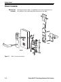
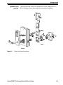
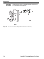

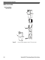
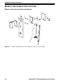

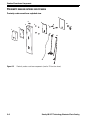
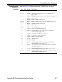
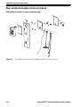
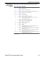

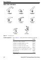
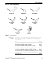
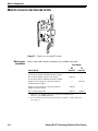
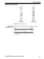
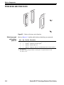
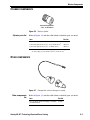

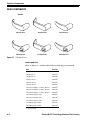
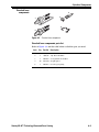
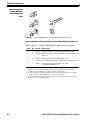
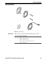
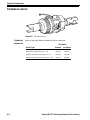
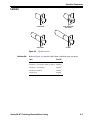
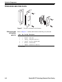
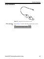

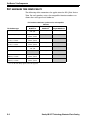

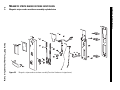
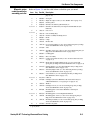
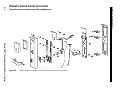
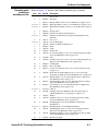
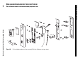

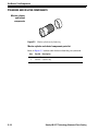
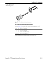
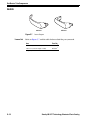
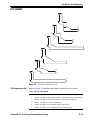
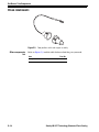
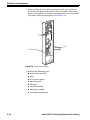
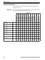
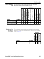
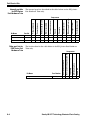
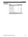
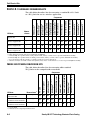


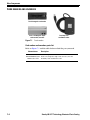
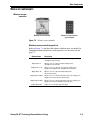
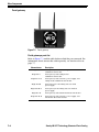
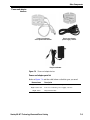
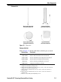
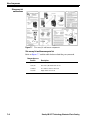
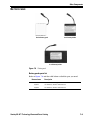
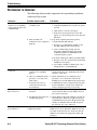
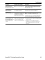
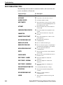
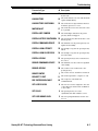


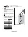
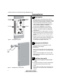
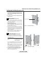
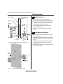
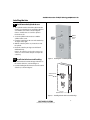
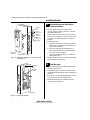
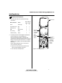
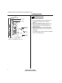
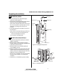
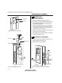
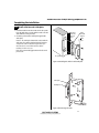
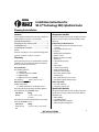
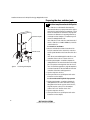
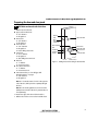
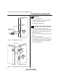
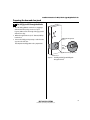
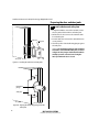
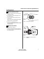
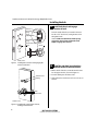
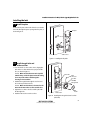
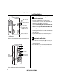

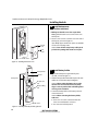
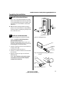
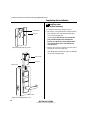
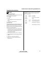

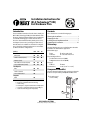
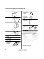
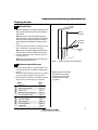
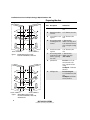
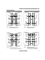
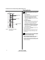
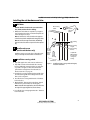
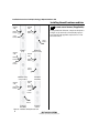
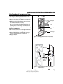
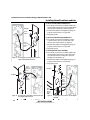
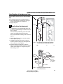
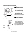
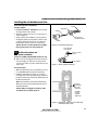
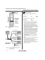
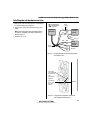
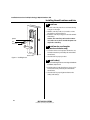
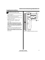
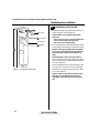
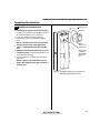


![B.A.S.I.S. G Service Manual [T63300]](http://vs1.manualzilla.com/store/data/006016632_1-3a9c260c4bb4c6128d680c6e76b28a8d-150x150.png)